

Page 1
/ Battery Charging Systems / Welding Technology / Solar Electronics
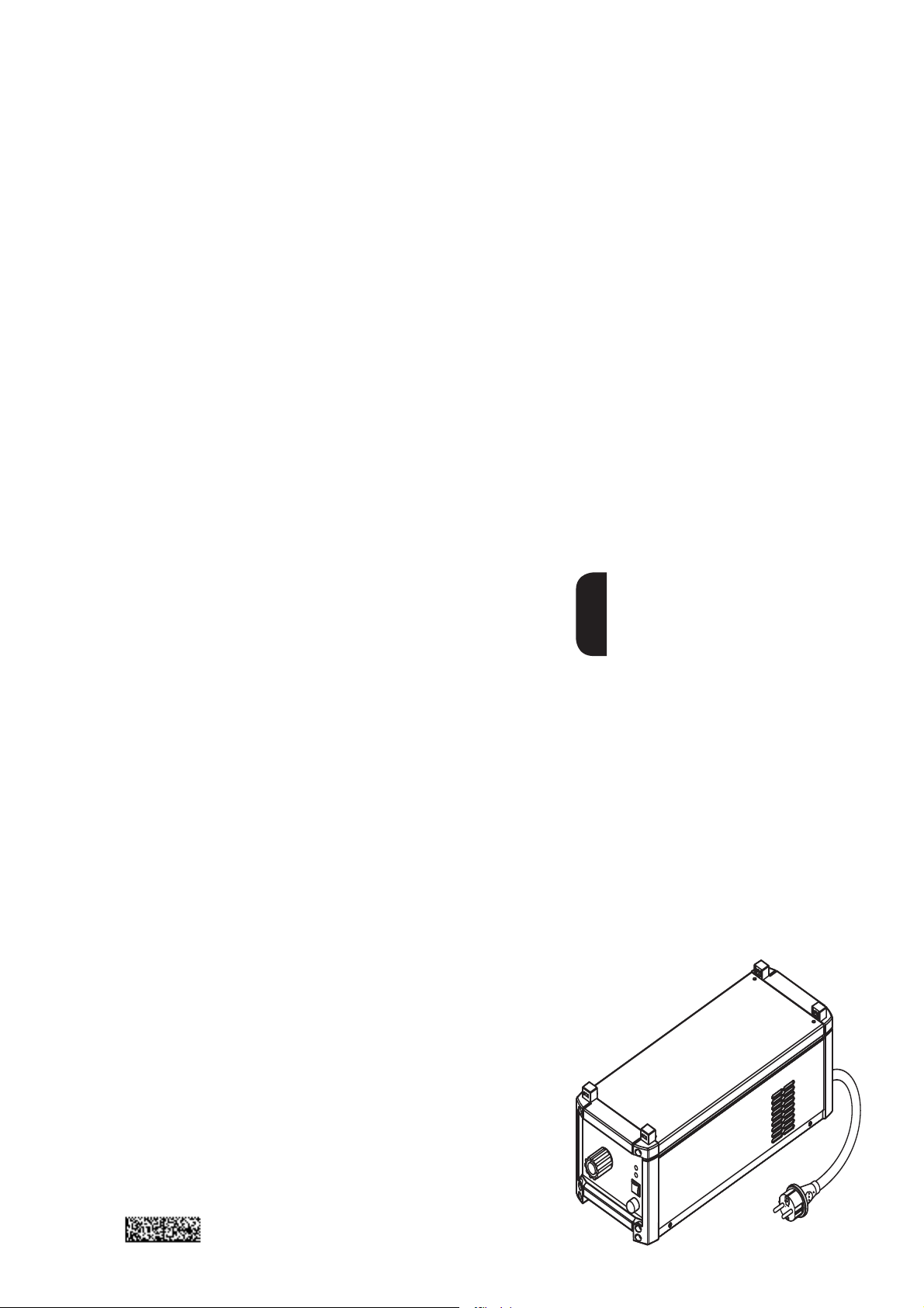
MagicCleaner Fume Abstractor
Operating Instructions
Spare Parts List
EN
Miscellaneus
42,0426,0026,EN 002-04042012
Page 2

Page 3

Dear Reader
Introduction
Thank you for choosing Fronius - and congratulations on your new, technically highgrade Fronius product! This instruction manual will help you get to know your new
machine. Read the manual carefully and you will soon be familiar with all the many
great features of your new Fronius product. This really is the best way to get the most
out of all the advantages that your machine has to offer.
Please also take special note of the safety rules - and observe them! In this way, you
will help to ensure more safety at your product location. And of course, if you treat your
product carefully, this definitely helps to prolong its enduring quality and reliability - things
which are both essential prerequisites for getting outstanding results.
EN
ud_fr_st_et_00493 01/2012
Page 4

Page 5

Contents
General remarks ........................................................................................................................................... 2
Machine concept ...................................................................................................................................... 2
Intended use ............................................................................................................................................ 2
Area of use .............................................................................................................................................. 2
Functional diagram .................................................................................................................................. 2
Scope of supply ....................................................................................................................................... 3
Technical Specification............................................................................................................................. 3
Controls, connection sockets and mechanical components......................................................................... 4
Front of MC fume extractor ...................................................................................................................... 4
Rear of MC fume extractor ...................................................................................................................... 4
Before Initial Operation ................................................................................................................................. 5
Intended Use ........................................................................................................................................... 5
Set-up requirements ................................................................................................................................ 5
Mains supply ............................................................................................................................................ 5
Initial Operation ............................................................................................................................................. 6
Safety ....................................................................................................................................................... 6
Fit suction nozzle ..................................................................................................................................... 6
Connect to power source ......................................................................................................................... 6
Initial Operation ........................................................................................................................................ 7
Replace activated carbon filter ..................................................................................................................... 8
General remarks ...................................................................................................................................... 8
Change activated carbon filter ................................................................................................................. 8
Replace activated carbon filter ahead of schedule ................................................................................ 10
Disposal of spent cartridges .................................................................................................................. 10
EN
Maintenance and care .................................................................................................................................11
General remarks .....................................................................................................................................11
At every initial operation ......................................................................................................................... 11
If the activated carbon filter is full ........................................................................................................... 11
Every 6 months .......................................................................................................................................11
Fault diagnosis - Fault rectification ............................................................................................................. 12
General .................................................................................................................................................. 12
Fault diagnosis - Fault rectification ........................................................................................................ 12
1
Page 6
General remarks
Machine concept
Intended use
The fully automatic MagicCleaner fume
extractor (MC Fume Extractor) is an
additional device to the MagicCleaner
CrNi-cleaning device. The fume extractor
is fixed onto the cleaning device. This
results in a compact CrNi-cleaning system
with extraction.
The housing of the MC fume extractor
contains the control electronics and the
suction unit, consisting of pre-filter felt,
activated carbon filter and suction turbine.
The suction performance is regulated via
the cleaning device current conduction:
The suction turbine works at maximum
output if maximum current is used. If no
cleaning current flows then the suction
turbine does not work at all.
Fig. 1 MC fume extractor and cleaning device
The MC fume extractor is used for removal of acidic vapours that occur during electrochemical cleaning of welding seams.
Area of use
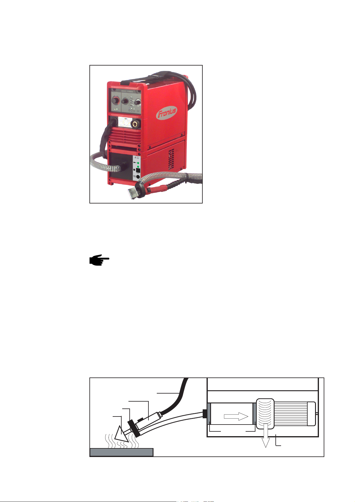
Functional
diagram
Note! The MC fume extractor only functions in conjunction with the MagicClea-
ner CrNi cleaning device.
The MC fume extractor can be used for a number of applications. Its low weight makes
it suitable above all for use on building sites.
The MC fume extractor is frequently used in
- Tank construction
- Construction of large-scale catering institutions
- Swimming pool construction
- Dairy construction
- Plant construction for medicines and foodstuffs
MagicCleaner CrNi-Cleaning Device
Hosepack to cleaning device
Cleaning handle
Suction nozzle
Cleaning
electrode
Suction hose
Activated
carbonfilter
Filter mats
Suction turbine
Turbine motor
Fig. 2 Functional diagram
Workpiece
Housing with
Exhaust air
2
control electronics
Page 7

Scope of supply
4 x Cable tie (can be reopened)
4 x M5 x 16 Extrude Tite Screw
EN
1 x MC fume extractor
1x suction hose 4 m incl. suction nozzle
Fig.3 Scope of supply MC fume extractor
Technical Specification
Supply voltage 230V
Mains voltage tolerance +/-15 %
Mains frequency 50 Hz
Rated power (incl. MagicCleaner cleaning device) 950 VA
Mains fuse protection 10 A slow-blow
Maximum suction power 110 m³/h
3928 cu.ft./h
Filter serviceable life approx. 300 hours
Net weight activated carbon filter 550 g
1.21 lb.
Type of protection IP 23
Dimensions l/w/h 430 / 180 / 180 mm
16.93 / 7.09 / 7.09 in.
Weight 5.5 kg
5.50 kg.
3
Page 8

Controls, connection sockets and mechanical components
Front of MC fume
extractor
Rear of MC fume
extractor
(1)
Fig. 4 Front of MC fume extractor
(6)
(1) Hose connection / filter fastening
(2) Mains supply display
(3) Filter display
(4) Reset button
(2)
(3)
(5) Turbine fuse
(4)
(5)
(6) Mains switch
(7) Socket with covering
Fig.5 Rear of MC fume extractor
(8) Power cable
(7)
(8)
4
Page 9

Before Initial Operation
Intended Use
Set-up requirements
The MC fume extractor must only be used for the removal of acidic vapours that arise
during electro-chemical cleaning of high-alloy steels.
The MC fume extractor must only be operated in conjunction with the MagicCleaner
CrNi cleaning device.
Any other form of use is seen as not the purpose for which the machine was intended.
The manufacturer will not be liable for damage arising from such improper use.
Intended use also comprises
- Following all information given in this manual
- Following all information given in the manual for the MagicCleaner CrNi-Cleaning
Device
- Performing all stipulated inspection and maintenance work
The MC fume extractor is tested to IP23, meaning:
- Protection from penetration by solid foreign bodies larger than Ø 12 mm
- Protection from water spray up to an angle of 60° to the vertical
In accordance with IP23 the MC fume extractor can be set up and operated outdoors.
The electrical parts fitted must be protected from direct moisture.
Important! Place the cleaning / extraction system on an even and firm floor in such a
way that it stands firmly.
EN
Mains supply
Air must be able to circulate freely around the air channels or air slots for turbine exhaust air. Any electroconductive metallic dust (e.g. from grinding work) must not be
allowed to be sucked into the machine.
The operating temperature and storage temperature for the cleaning/extraction system
must not drop below -10°C. Set up the cleaning/extraction system so that additional
heating due to heat sources such as radiators, heating or annealing furnaces, direct
insulation etc. is avoided.
The MC fume extractor is designed for the supply voltage given on the rating plate. If
the mains cable or mains plug are not fitted on your equipment model, then they must
be fitted in accordance with national standards. The technical specification provides
information regarding fuse protection for the mains cable.
Note! Inadequately dimensioned electrical installations can lead to serious
damage to property. The mains plug, mains supply lead, as well as their fuse
protection, must always be designed accordingly.
Any electrical intervention, including fitting or removal of the mains plug may only be
carried out by a qualified electrician.
5
Page 10

Initial Operation
Warning! Incorrect operation can cause serious personal injury and damage
to property. Only use the functions described when the following documents
have been read completely and understood:
- This Owner’s Manual
- All manuals for the system components ( MAGIC CLEANER CrNi-Cleaning Device), in particular the safety regulations
Safety
Fit suction nozzle
Connect to
power source
1. 2.
1
2
3
4
6
5
2
4
Fig.6 Preparation
3
2
1
Fig.7 Fit suction nozzle
3. Fasten the suction hose to the hosepack of the MagicCleaner CrNi Cleaning device
using 4 cable ties.
Note! The MagicCleaner CrNi Cleaning Device is not switched on at the same
time if main switch (6) of the MC fume extractor is operated.
1
The MagicCleaner CrNi-Cleaning Device
is ready to run when
2
Fig.8 Connect to power source
- the cleaning device power cable has
- the MC fume extractor power cable is
- the program switch for the cleaning
6
Caution! Danger of damage to
the workpiece and triangle due
to current conduction. As soon
as the mains cable from the MC
fume extractor is connected to
the mains supply, cleaning
current will flow if the program
switch is set to the appropriate
position.
Lay the cleaning handle down so
that it is insulated!
been inserted in the MC fume extractor socket,
connected to the mains supply and
device is set to the desired operating
mode.
Page 11

Initial Operation
Caution! The loud operating noise from the turbine can cause damage to
hearing. Use suitable ear protection!
1. Take protective measures for operating the MagicCleaner CrNi Cleaning Device
2. Switch main switch (6) into position „I“
The MC fume extractor is ready to run.
The fume extractor only works during the actual cleaning procedure using the
MagicCleaner CrNi Cleaning Device. The suction turbine is regulated via the
cleaning current:
Maximum cleaning current ..... Suction turbine working at full capacity
Cleaning current 50 % ........... Suction turbine working at half capacity
EN
7
Page 12

Replace activated carbon filter
Warning! An electric shock can be fatal. Before opening the machine
- Switch the mains switch into the “O” position
- Unplug the machine from the mains
- Display an easily understood sign warning against the danger of switching
the machine back on
- Using a suitable measuring device, ensure that the components under
electric charge (e.g. capacitors) have been discharged
General remarks
The degree of contamination of the activated carbon filter is shown on the filter display (2).
Filter display (2) off:
The activated carbon filter is clean or only
slightly dirty. The activated carbon filter
can absorb contaminants.
Filter display (2) on:
The activated carbon filter is very dirty or
(3)
full. The activated carbon filter cannot
absorb any more contaminants.
Important! When the filter display (2)
lights up the activated carbon filter and
the appropriate filter mat must be replaced within the next 12 operating hours.
Fig. 9 Filter display
Note! Always replace used activated carbon filters and associated filter mats
with new filters and filter mats,
- never re-use used filters and filter mats,
- dispose of used filters and filter mats in accordance with official regulati-
ons.
Change activated
carbon filter
1. Switch main switch (6) into position „0“
2. Unplug the mains cable (8) from the mains supply
3.
2
1
Fig.10 Remove the left-hand side panel and
remove the suction hose
3
4
8
Caution! Risk of injury due to
acid in the suction hose. Wear
suitable safety glasses and
safety gloves when pulling the
suction hose off.
Caution! Inadequate protective
conductor connection can cause
serious personal injury and
damage to property. The housing
screws represent a suitable
protective conductor connection
for earthing the housing and
must not be replaced by other
screws without a reliable protective conductor connection.
Page 13

Replace activated carbon filter
(continued)
4.
Caution! Risk of injury due to
acid. Use suitable safety gloves
when touching the filter cartridge
or the filter mats.
2
Filter cartridge
3
2 x Filter mat
Fig.11 Remove the filter cartridge and the filter
mats (2x)
5.
1
1
1
Note! Place the filter cartridge or
the filter mats in an acid resistant
EN
container and ensure that it is not
possible for other persons to
access the filter cartridge or the
filter mats.
Important! Insert the filter mats in the
following manner :
- on the turbine end: the blue side must
face the filter cartridge
- on the hose connection end: the blue
side must face the hose connection /
filter mount
2
Fig.12 Insert the new filter cartridge and the new
filter mats (2x)
3
6.
1
2
Fig.13 Fit the left-hand side panel and insert
suction hose
3
Caution! Risk of injury due to
acid in the suction hose. Wear
suitable safety glasses and
safety gloves when putting the
suction hose in place.
4
9
Page 14

Replace activated carbon filter
(continued)
7. Connect mains cable (8) to mains power supply
8. Set mains switch (6) to “I” position - filter indicator (3) lights up
9. Press “Reset” button (4) and hold approx. 10 secs until filter indicator (3) goes off
Caution! Suction efficiency is impaired if activated carbon filter is full. Only
press “Reset” button (4) if the activated carbon filter has actually been
replaced!
Replace activated carbon filter
ahead of schedule
Disposal of spent
cartridges
Procedure in the event that the activated carbon filter has to be replaced ahead of
schedule e.g. if the activated carbon filter has suffered mechanical damage (filter
indicator (3) fails to light up):
1. Replace the activated carbon filter and the associated filter mats
Note! Always replace used activated carbon filters and associated filter mats
with new filters and filter mats,
- never re-use used filters and filter mats,
- dispose of used filters and filter mats in accordance with official regulations.
2. Connect mains cable (8) to mains power supply
3. Set mains switch (6) to “I” position
4. Press “Reset” button (4)
Filter indicator (3) lights up
5. Press “Reset” button (4) and hold approx. 10 secs until filter indicator (3) goes off
Important! Acidic materials may only be disposed off in line with official national and
international guidelines.
The composition of the activated carbon filter means that it can be incinerated completely for disposal purposes.
Fig. 14 Composition of the activated carbon filter
Filter pipe and perforated plates made from PVC
Filter material made from impregnated activated carbon
Non-woven filter fabric made from polyolefin
Electrolyte:
Maximum 180 g phosphoric acid (P2O5) per cartridge
Maximum 50 g sulphuric acid (P2O4) per cartridge
Filter mats made from latex bonded natural fibres and
animal hair
10
Page 15

Maintenance and care
General remarks Under normal operating conditions the MC fume extractor only requires a minimum of
care and maintenance. However it is imperative that a few points are followed in order
to keep the system operational over many years.
Warning! An electric shock can be fatal. Before opening, switch the device off,
remove the mains plug and fit a clearly legible and easily understood warning
sign against switching the machine back on - discharge the electrolytic capacitators if necessary. The screws for the case represent a suitable conductor
connection for earthing the case. The screws must NOT be replaced by any
other screws without a reliable PE conductor connection.
EN
At every initial
operation
If the activated
carbon filter is
full
Every 6 months
Check the following parts for possible damage:
- Socket, mains plug and mains cable
- Mains plug and mains cable for the MagicCleaner CrNi Cleaning Device
- Cleaning handle and cleaning handle hosepack for the MagicCleaner CrNi Cleaning Device
Check the ventilation flaps or air slots for turbine exhaust air and that air circulation is
unimpeded. The ventilation flaps or the air slots for the turbine exhaust air must not be
covered in any way, not even partially.
- Replace activated carbon filter
- Replace filter mats
Note! Always replace used activated carbon filters and associated filter mats
with new filters and filter mats,
- never re-use used filters and filter mats,
- dispose of used filters and filter mats in accordance with official regulati-
ons.
Caution! Risk of injury due to acid or acidic materials. When cleaning the MC
fume extractor using compressed air, use suitable safety gloves and suitable
eye protection.
Do not point the MC fume extractor in the direction of other people when
cleaning it with compressed air.
- Dismantle the extractor‘s side panels and blow the inside of the device clean
using dry, pressure-reduced compressed air
Note! Electronic components may be damaged by compressed air. Do not
aim airjets at electronic components from too close a range.
- Clean ventilation flaps or air slots for turbine exhaust air
11
Page 16

Fault diagnosis - Fault rectification
General All faults detected by the MC fume extractor are displayed by way of MC mains indica-
tor (2) and filter indicator (3) .
After switching on the extractor, both indicators light up for approx. 1 sec during the
start-up phase. During the start-up phase, the MC fume extractor checks the mains
voltage present .
Fault diagnosis Fault rectification
Mains supply indicator (1) is not lit
Mains switch in “I” position
Cause: Fault in the power feed
Remedy: Check mains cable, mains plug, and mains protection
Mains indicator (2) flashes
Mains switch in “I” position
Cause: Inadmissible mains fluctuations when device is switched on
Remedy: Check mains for voltage and frequency, switch device on again
Mains indicator (2) flashes
Suction turbine not working
Cause: Turbine fuse (3) faulty
Remedy: Replace turbine fuse (3):
- Set mains switch (6) to “0” position
- Disconnect mains cable (8) from mains supply
- Replace turbine fuse (3)
- Connect mains cable (8) to mains supply
- Set mains switch (6) to “I” position - mains indicator (2) goes off
Cause: Temperature in device too high
Remedy: Allow device to cool down
Filter display (2) on
Cause: Activated carbon filter is full
Remedy: Replace activated carbon filter and filter mats
Suction power not achieved
Cause: Bend in the suction hose; suction hose or suction nozzle are installed
incorrectly
Remedy: Remove bend from suction hose, check suction hose and suction nozzle
for foreign bodies, remove foreign bodies
12
Page 17

Ersatzteilliste
DEENFRITESPT-BRNLNOCSRUSKSVTR
Spare Parts List
Liste de pièces de rechange
Lista parti di ricambio
Lista de repuestos
Lista de peças sobresselentes
Onderdelenlijst
Reservdelsliste
Seznam náhradních dílù
Список запасных частей
Zoznam náhradných dielov
Reservdelslistan
ud_fr_st_tb_00150 012012
Parça Listesi
Czyszczenie palnika
PL
Page 18

Exhaust device MagicCleaner 4,045,884
AM2,0201,1727
AM2,0201,1726
AM2,0201,1725
* gewünschte Länge angeben
* Specify the length required
* Indiquer la longueur désirée
* Indicar la longitud deseada
* Indicare la lunghezza desiderat
* indicar o comprimento desejado
* uved'te požadovanou délku
42,0300,2602
42,0300,2568
42,0100,1146
43,0006,0180
43,0003,0316
43,0003,0315
44,0001,1337
42,0300,2602
42,0100,1145
42,0405,0367
42,0100,1147
42,0405,0193
43,0002,0360
41,0007,0047 - 250V/4A
41,0007,0076
41,0007,0169
45,0200,1191
41,0007,0079
43,0002,0295
42,0300,0648
42,0405,0367
43,0004,0519
4,070,849
44,0350,2295
40,0001,0431 - *
42,0407,0558
Exhaust device MagicCleaner
Ersatzteilliste / Spare parts list / Listes de pièces de rechange / Lista de repuestos / Lista de pecas sobresselentes / Lista dei Ricambi
el_fr_st_so_00873 012004
1/1
Page 19

FRONIUS INTERNATIONAL GMBH
Froniusplatz 1, A-4600 Wels, Austria
Tel: +43 (0)7242 241-0, Fax: +43 (0)7242 241-3940
E-Mail: sales@fronius.com
www.fronius.com
Under http://www.fronius.com/addresses you will find all addresses
www.fronius.com/addresses
of our Sales & service partners and Locations.
ud_fr_st_so_00082 012011
 Loading...