

Page 1

/ Battery Charging Systems / Welding Technology / Solar Electronics
DE
EN
FR
Automaten-Interface
Machine interface
Interface automates
Einbauanleitung
Systemerweiterung
Installation instructions
System extension
Instructions d'installation
Extension système
42,0410,1626 005-25042013
Page 2

0
Page 3

Inhaltsverzeichnis
Allgemeines ............................................................................................................................................... 3
Lieferumfang......................................................................................................................................... 3
Erforderliches Werkzeug....................................................................................................................... 3
Automaten-Interface in TSt 3500/5000 einbauen ...................................................................................... 4
Sicherheit.............................................................................................................................................. 4
Gerät öffnen.......................................................................................................................................... 4
Automaten-Interface einbauen.............................................................................................................. 5
Gerät schließen..................................................................................................................................... 7
Automaten-Interface in TSt 3500/5000 Rob einbauen...............................................................................8
Sicherheit.............................................................................................................................................. 8
Gerät öffnen.......................................................................................................................................... 8
Automaten-Interface einbauen.............................................................................................................. 9
Gerät schließen..................................................................................................................................... 11
DE
1
Page 4

2
Page 5

Allgemeines
DE
Lieferumfang
Erforderliches
Werkzeug
(1)
(2)
(3)
(4)
(5)
(6)
- Innensechskant-Schlüssel SW 8 mm
- Gabelschlüssel SW 21 mm
- Schraubendreher TX 25
- Hand Drehmoment-Schrauber 0,2 - 6 Nm
(1) Automaten-Interface
(2) Kunststoff-Mutter für Knickschutz
(3) Kabelbaum
(4) 3 Kunststoff-Distanzen 30 mm
(1.18 in.), 1 Messingdistanz 30 mm
(1.18 in.)
(5) 3 Kunststoff-Distanzen 12 mm
(0.47 in.), 1 Messingdistanz 12 mm
(0.47 in.)
(6) Knickschutz
3
Page 6

Automaten-Interface in TSt 3500/5000 einbauen
Sicherheit
WARNUNG! Fehlbedienung und fehlerhaft durchgeführte Arbeiten können
schwerwiegende Personen- und Sachschäden verursachen.
Alle in diesem Dokument beschriebenen Arbeiten und Funktionen dürfen nur von
geschultem Fachpersonal ausgeführt werden, wenn folgende Dokumente vollständig gelesen und verstanden wurden:
- dieses Dokument
- sämtliche Dokumente der Systemkomponenten, insbesondere Sicherheitsvorschriften
WARNUNG! Ein elektrischer Schlag kann tödlich sein. Vor Beginn der Arbeiten
- Netzschalter der Stromquelle in Stellung - O - schalten
- Stromquelle vom Netz trennen
- ein verständliches Warnschild gegen Wiedereinschalten anbringen
Nach dem Öffnen des Gerätes mit Hilfe eines geeigneten Messgerätes sicherstellen, dass elektrisch geladene Bauteile (z.B. Kondensatoren) entladen sind.
Zusätzlich vor Beginn der Arbeiten alle weiteren beteiligten Geräte und Komponenten
- ausschalten
- vom Netz trennen
- gegen Wiedereinschalten sichern
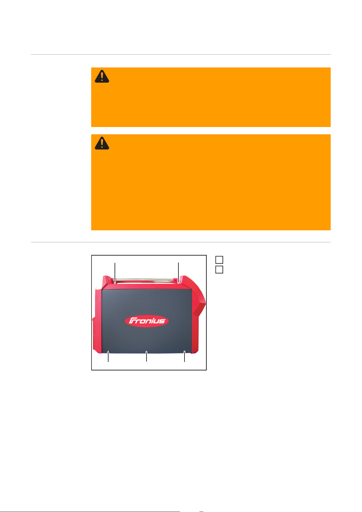
Gerät öffnen
(1)
(1)
(1)
(1)
(1)
5 Schrauben TX 25 (1) lösen
1
Seitenteil entfernen
2
4
Page 7

Automaten-Interface einbauen
(1)
(2)
Blindabdeckung (1) entfernen
1
Knickschutz (2) wie abgebildet auf Ge-
2
räte-Rückseite aufsetzen
DE
(3)
Knickschutz mittels Mutter (3) fest-
3
schrauben
5
Page 8

(4)
(4)
3 Kunststoff-Distanzen 30 mm auf be-
4
reits vorhandene Kunststoff-Distanzen
(4) aufschrauben
- Anzugsmoment = 0,2 Nm
1 Messingdistanz 30 mm auf bereits
5
vorhandene Messingdistanz (5) aufschrauben
- Anzugsmoment = 1,5 Nm
(4)
(6)
(6) (7)
(5)
(6)
(9)
(8)
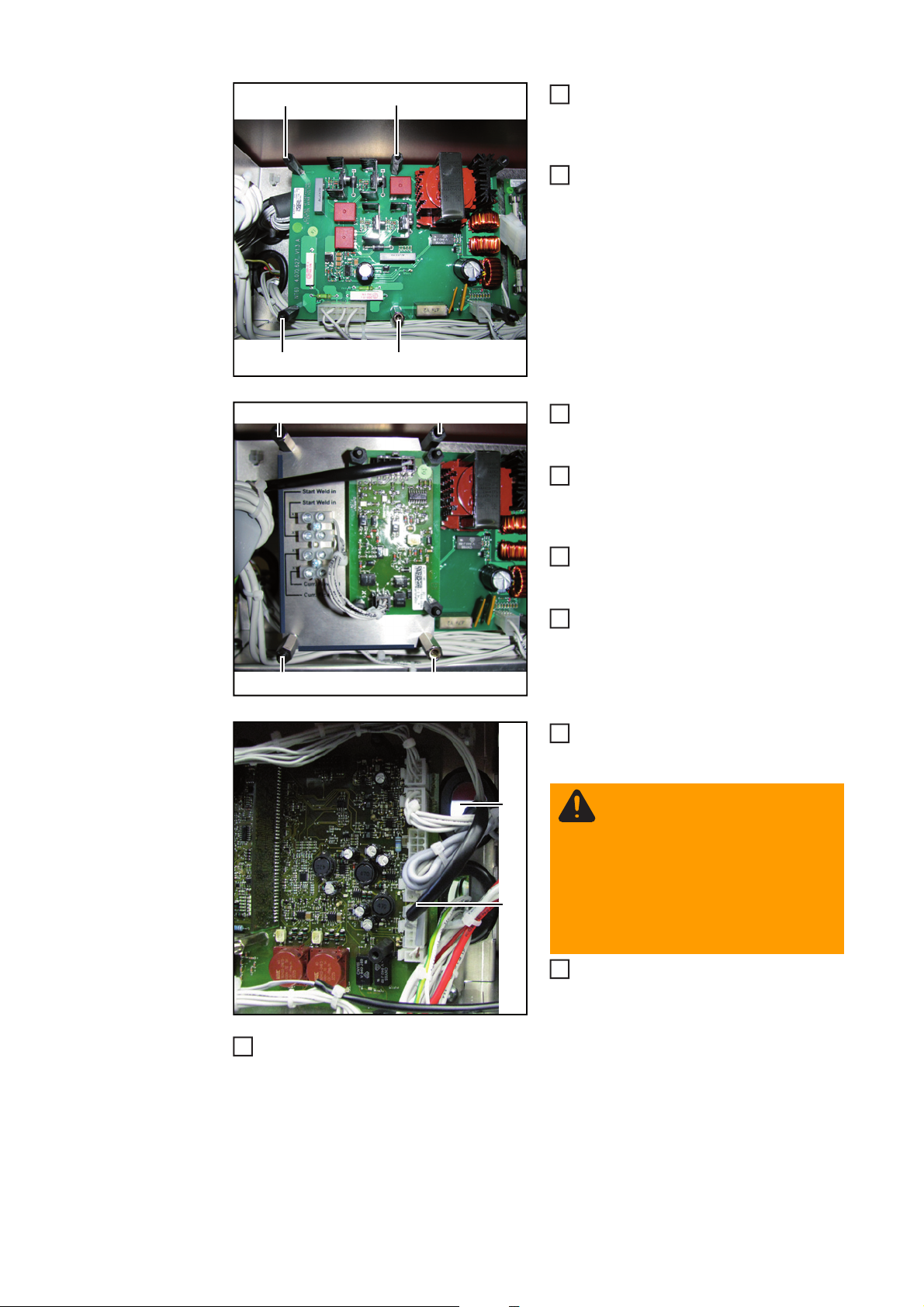
Automaten-Interface wie abgebildet
6
auf Distanzen am Print NT2501 aufsetzen
Automaten-Interface mittels 3 Kunst-
7
stoff-Distanzen 12 mm (6) festschrauben
- Anzugsmoment = 0,2 Nm
Automaten-Interface mittels 1 Mes-
8
singdistanz 12 mm (7) festschrauben
- Anzugsmoment = 1,5 Nm
Kabelbaum an Automaten-Interface
9
anstecken
Kabelbaum des Automaten-Interface
10
(8) durch Durchführung (9) durchführen
WARNUNG! Ein elektrischer
Schlag kann tödlich sein. Bei der
Montage des Kabelbaumes darauf achten, dass ein Abstand von
mindestens 20 mm (0.79 in.) zwischen Kabelbaum und dem nicht
isolierten Bereich der ElektrolytKondensatoren gegeben ist und
immer bestehen bleibt.
Kabelbaum des Automaten-Interface
11
11
wie abgebildet an Sockel X6 des Print
LSTMAG 35/50 anstecken
Externe Verkabelung an Anschlussklemme des Automaten-Interface anschließen
12
(laut Schaltplan und Aufdruck neben der Anschlussklemme)
6
Page 9

Gerät schließen
(1)
(1)
(1)
(1)
(1)
2
Seitenteil einsetzen
1
5 Schrauben TX 25 (1) festschrauben
DE
7
Page 10
Automaten-Interface in TSt 3500/5000 Rob einbauen
Sicherheit
WARNUNG! Fehlbedienung und fehlerhaft durchgeführte Arbeiten können
schwerwiegende Personen- und Sachschäden verursachen.
Alle in diesem Dokument beschriebenen Arbeiten und Funktionen dürfen nur von
geschultem Fachpersonal ausgeführt werden, wenn folgende Dokumente vollständig gelesen und verstanden wurden:
- dieses Dokument
- sämtliche Dokumente der Systemkomponenten, insbesondere Sicherheitsvorschriften
WARNUNG! Ein elektrischer Schlag kann tödlich sein. Vor Beginn der Arbeiten
- Netzschalter der Stromquelle in Stellung - O - schalten
- Stromquelle vom Netz trennen
- ein verständliches Warnschild gegen Wiedereinschalten anbringen
Nach dem Öffnen des Gerätes mit Hilfe eines geeigneten Messgerätes sicherstellen, dass elektrisch geladene Bauteile (z.B. Kondensatoren) entladen sind.
Zusätzlich vor Beginn der Arbeiten alle weiteren beteiligten Geräte und Komponenten
- ausschalten
- vom Netz trennen
- gegen Wiedereinschalten sichern
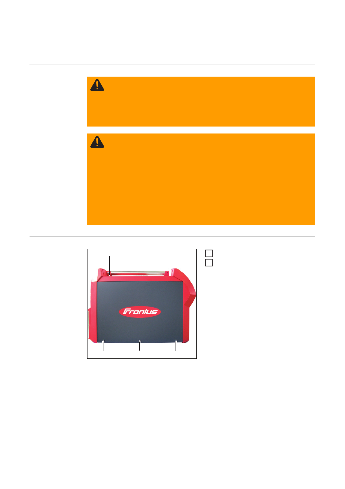
Gerät öffnen
(1)
(1)
(1)
(1)
(1)
5 Schrauben TX 25 (1) lösen
1
Seitenteil entfernen
2
8
Page 11

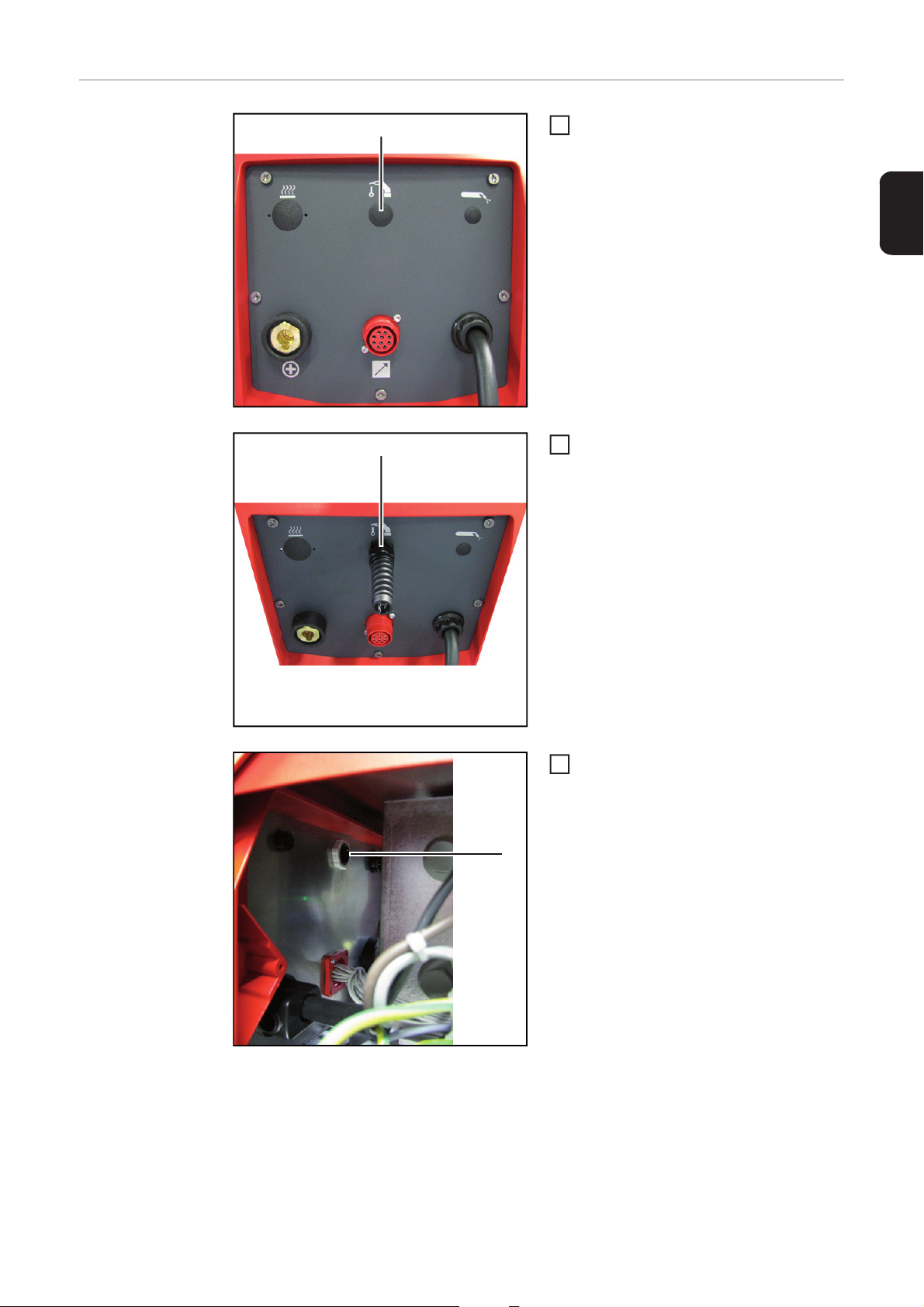
Automaten-Interface einbauen
(1)
(2)
Blindabdeckung (1) entfernen
1
Knickschutz (2) wie abgebildet auf Ge-
2
räte-Rückseite aufsetzen
DE
(3)
Knickschutz mittels Mutter (3) fest-
3
schrauben
9
Page 12
(4)
(4)
3 Kunststoff-Distanzen 12 mm auf be-
4
reits vorhandene Kunststoff-Distanzen
(4) aufschrauben
- Anzugsmoment = 0,2 Nm
1 Messingdistanz 12 mm auf bereits
5
vorhandene Messingdistanz (5) aufschrauben
- Anzugsmoment = 1,5 Nm
(4)
(6)
(6) (7)
(5)
(6)
(9)
(8)
Automaten-Interface wie abgebildet
6
auf Distanzen am Print NT60 aufsetzen
Automaten-Interface mittels 3 Kunst-
7
stoff-Distanzen 30 mm (6) festschrauben
- Anzugsmoment = 0,2 Nm
Automaten-Interface mittels 1 Mes-
8
singdistanz 30 mm (7) festschrauben
- Anzugsmoment = 1,5 Nm
Kabelbaum an Automaten-Interface
9
anstecken
Kabelbaum des Automaten-Interface
10
(8) durch Durchführung (9) durchführen
WARNUNG! Ein elektrischer
Schlag kann tödlich sein. Bei der
Montage des Kabelbaumes darauf achten, dass ein Abstand von
mindestens 20 mm (0.79 in.) zwischen Kabelbaum und dem nicht
isolierten Bereich der ElektrolytKondensatoren gegeben ist und
immer bestehen bleibt.
Kabelbaum des Automaten-Interface
11
11
wie abgebildet an Sockel X6 des Print
LSTMAG 35/50 anstecken
10
Externe Verkabelung an Anschlussklemme des Automaten-Interface anschließen
12
(laut Schaltplan und Aufdruck neben der Anschlussklemme)
Page 13

Gerät schließen
(1)
(1)
(1)
(1)
(1)
2
Seitenteil einsetzen
1
5 Schrauben TX 25 (1) festschrauben
DE
11
Page 14

12
Page 15

Contents
General ...................................................................................................................................................... 15
Scope of supply .................................................................................................................................... 15
Tools required....................................................................................................................................... 15
Installing the machine interface in the TSt 3500/5000 power source ........................................................ 16
Safety.................................................................................................................................................... 16
Opening the device............................................................................................................................... 16
Installing the machine interface ............................................................................................................ 17
Closing the housing .............................................................................................................................. 19
Installing the machine interface in the TSt 3500/5000 Rob power source................................................. 20
Safety.................................................................................................................................................... 20
Opening the device............................................................................................................................... 20
Installing the machine interface ............................................................................................................ 21
Closing the housing .............................................................................................................................. 23
EN
13
Page 16

14
Page 17

General
Scope of supply
Tools required - 8 mm Allen key
- 21 mm flat spanner
- TX 25 screwdriver
- 0.2 - 6 Nm manual torque wrench
(1) Machine interface
(2) Plastic nuts for anti-kink protection
(3) Cable harness
(4) Three 30 mm (1.18 in.) plastic
(1)
(2)
(3)
(5) Three 12 mm (0.47 in.) plastic
(4)
(6) Anti-kink protection
(5)
(6)
spacers, one 30 mm (1.18 in.) brass
spacer
spacers, one 12 mm (0.47 in.) brass
spacer
EN
15
Page 18
Installing the machine interface in the TSt 3500/5000
power source
Safety
WARNING! Incorrect operation or shoddy workmanship can cause serious injury
or damage.
All functions described in this document may only be carried out by trained and
qualified personnel after they have fully read and understood the following documents:
- this document
- all documents relating to the system components, especially the safety rules
WARNING! An electric shock can be fatal. Before starting work:
- turn the power source mains switch to the "O" position
- disconnect the power source from the mains
- put up an easy-to-understand warning sign to stop anybody inadvertently
switching it back on again
After opening the device, use a suitable measuring instrument to check that electrically charged components (e.g. capacitors) have been discharged.
Before starting work, also ensure that all other devices and components are
- switched off
- disconnected from the mains
- prevented from being switched back on again.
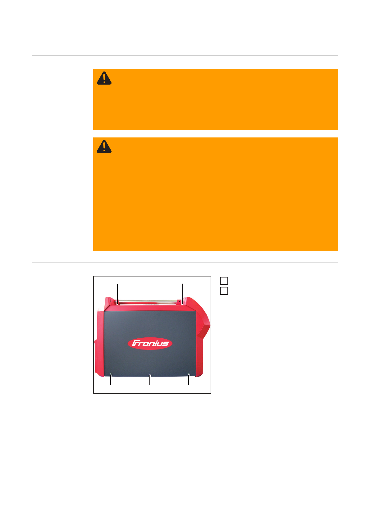
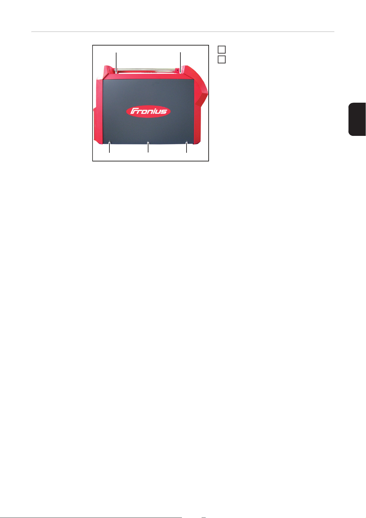
Opening the device
(1)
(1)
(1)
(1)
(1)
Undo 5 x TX 25 screws (1)
1
Remove the side panel
2
16
Page 19
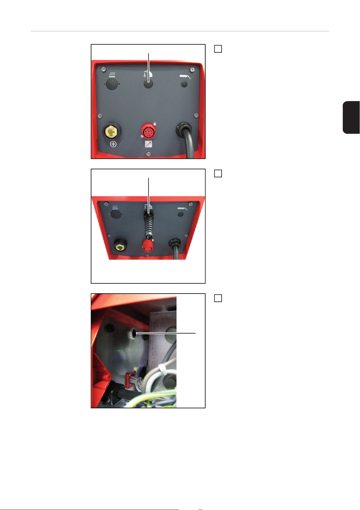
Installing the machine interface
(1)
(2)
Remove blanking cover (1)
1
Place the anti-kink protection (2) on the
2
rear of the device as shown
EN
(3)
Tighten the anti-kink protection using
3
nut (3)
17
Page 20

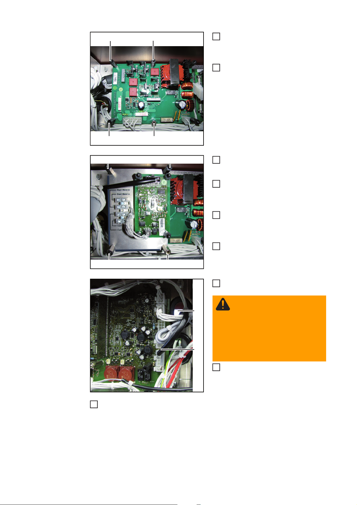
(4)
(4)
Screw three 30 mm plastic spacers
4
onto the existing plastic spacers (4)
- Tightening torque = 0.2 Nm
Screw one 30 mm brass spacer onto
5
the existing brass spacer (5)
- Tightening torque = 1.5 Nm
(4)
(6)
(6) (7)
(5)
(6)
(9)
(8)
Place the machine interface onto the
6
spacers on the NT2501 PC board as
shown
Tighten the machine interface using
7
three 12 mm plastic spacers (6)
- Tightening torque = 0.2 Nm
Tighten the machine interface using
8
one 12 mm brass spacer (7)
- Tightening torque = 1.5 Nm
Connect the cable harness to the ma-
9
chine interface
Feed the cable harness of the machine
10
interface (8) through bushing (9)
WARNING! An electric shock can
be fatal. When connecting the cable harness, ensure that a distance of at least 20 mm (0.79 in.)
is always maintained between the
cable harness and the non-insulated area of the electrolyte capacitors.
Connect the cable harness of the ma-
11
11
chine interface to the X6 socket on the
LSTMAG 35/50 PC board as shown
18
Connect the external cables to the terminal of the machine interface (according to the
12
circuit diagram and labelling next to the terminal)
Page 21

Closing the hous-
(1)
(1)
(1)
(1)
(1)
2
ing
Insert side panel
1
Tighten five TX 25 screws (1)
EN
19
Page 22

Installing the machine interface in the TSt 3500/5000
Rob power source
Safety
WARNING! Incorrect operation or shoddy workmanship can cause serious injury
or damage.
All functions described in this document may only be carried out by trained and
qualified personnel after they have fully read and understood the following documents:
- this document
- all documents relating to the system components, especially the safety rules
WARNING! An electric shock can be fatal. Before starting work:
- turn the power source mains switch to the "O" position
- disconnect the power source from the mains
- put up an easy-to-understand warning sign to stop anybody inadvertently
switching it back on again
After opening the device, use a suitable measuring instrument to check that electrically charged components (e.g. capacitors) have been discharged.
Before starting work, also ensure that all other devices and components are
- switched off
- disconnected from the mains
- prevented from being switched back on again.
Opening the device
(1)
(1)
(1)
(1)
(1)
Undo 5 x TX 25 screws (1)
1
Remove the side panel
2
20
Page 23

Installing the machine interface
(1)
(2)
Remove blanking cover (1)
1
Place the anti-kink protection (2) on the
2
rear of the device as shown
EN
(3)
Tighten the anti-kink protection using
3
nut (3)
21
Page 24

(4)
(4)
Screw three 12 mm plastic spacers
4
onto the existing plastic spacers (4)
- Tightening torque = 0.2 Nm
Screw one 12 mm brass spacer onto
5
the existing brass spacer (5)
- Tightening torque = 1.5 Nm
(4)
(6)
(6) (7)
(5)
(6)
(9)
(8)
Place the machine interface onto the
6
spacers on the NT60 PC board as
shown
Tighten the machine interface using
7
three 30 mm plastic spacers (6)
- Tightening torque = 0.2 Nm
Tighten the machine interface using
8
one 30 mm brass spacer (7)
- Tightening torque = 1.5 Nm
Connect the cable harness to the ma-
9
chine interface
Feed the cable harness of the machine
10
interface (8) through bushing (9)
WARNING! An electric shock can
be fatal. When connecting the cable harness, ensure that a distance of at least 20 mm (0.79 in.)
is always maintained between the
cable harness and the non-insulated area of the electrolyte capacitors.
Connect the cable harness of the ma-
11
11
chine interface to the X6 socket on the
LSTMAG 35/50 PC board as shown
22
Connect the external cables to the terminal of the machine interface (according to the
12
circuit diagram and labelling next to the terminal)
Page 25

Closing the hous-
(1)
(1)
(1)
(1)
(1)
2
ing
Insert side panel
1
Tighten five TX 25 screws (1)
EN
23
Page 26

24
Page 27

Sommaire
Généralités................................................................................................................................................. 27
Livraison................................................................................................................................................ 27
Outils requis.......................................................................................................................................... 27
Monter l'interface automates dans TSt 3500/5000 .................................................................................... 28
Sécurité................................................................................................................................................. 28
Ouvrir l'appareil..................................................................................................................................... 28
Monter l'interface automates................................................................................................................. 29
Fermer l'appareil ................................................................................................................................... 31
Monter l'interface automates dans le TSt 3500/5000 Rob ......................................................................... 32
Sécurité................................................................................................................................................. 32
Ouvrir l'appareil..................................................................................................................................... 32
Monter l'interface automates................................................................................................................. 33
Fermer l'appareil ................................................................................................................................... 35
FR
25
Page 28

26
Page 29

Généralités
Livraison
(1)
(2)
(3)
(4)
(5)
(6)
Outils requis - Clé pour vis à six pans creux SW 8 mm
- Clé à fourche SW 21 mm
- Tournevis TX 25
- Tournevis dynamométrique manuel 0,2 - 6 Nm
(1) Interface automates
(2) Écrou en plastique pour protection
anti-coude
(3) Faisceau de câbles
(4) 3 pièces d'écartement en plastique
30 mm (1.18 in.), 1 pièce d'écarte-
ment en laiton 30 mm (1.18 in.)
(5) 3 pièces d'écartement en plastique
12 mm (0.47 in.), 1 pièce d'écarte-
ment en laiton 12 mm (0.47 in.)
(6) Protection anti-coude
FR
27
Page 30
Monter l'interface automates dans TSt 3500/5000
Sécurité
AVERTISSEMENT ! Les erreurs de manipulation ou les erreurs en cours d'opé-
ration peuvent entraîner des dommages corporels et matériels graves.
Tous les travaux et fonctions décrits dans le présent document ne doivent être
effectués que par un personnel qualifié ayant entièrement lu et compris les documents suivants :
- le présent document,
- tous les documents relatifs aux composants périphériques, en particulier les
consignes de sécurité.
AVERTISSEMENT ! Une décharge électrique peut être mortelle. Avant d'entamer les travaux :
- Placer l'interrupteur secteur de la source de courant en position - O -.
- Débrancher la prise secteur de la source de courant.
- Apposer un panneau d'avertissement compréhensible afin de prévenir toute
remise en marche.
Après ouverture de l'appareil, s'assurer, à l'aide d'un appareil de mesure approprié, que les composants à charge électrique (condensateurs par ex.) sont déchargés.
Avant le début des travaux
- déconnecter tous les autres appareils et composants,
- les débrancher du réseau,
- s'assurer qu'il soit impossible de les rallumer.
Ouvrir l'appareil
(1)
(1)
(1)
(1)
(1)
Desserrer les 5 vis TX 25 (1)
1
Retirer le panneau latéral
2
28
Page 31
Monter l'interface
automates
(1)
(2)
Retirer la fausse prise (1)
1
Placer la protection anti-coude (2) tel
2
qu'indiqué sur l'illustration
FR
(3)
Visser la protection anti-coude avec
3
l'écrou (3)
29
Page 32

(4)
(4)
Visser les 3 pièces d'écartement en
4
plastique 30 mm sur les pièces d'écartement plastique (4) déjà existantes.
- Couple de serrage = 0,2 Nm
Visser 1 pièce d'écartement en laiton
5
30 mm sur la pièce d'écartement en
laiton (5) déjà existante.
- Couple de serrage = 1,5 Nm
(4)
(6)
(6) (7)
(5)
(6)
(9)
(8)
Placer l'interface automates sur les
6
distances sur le circuit imprimé
NT2501, tel qu'indiqué sur l'illustration.
Fixer l'interface automates par vissage
7
à l'aide de 3 pièces d'écartement en
plastique de 12 mm (6).
- Couple de serrage = 0,2 Nm
Fixer l'interface automates par vissage
8
à l'aide de 1 pièce d'écartement en laiton 12 mm (7).
- Couple de serrage = 1,5 Nm
Brancher le faisceau de câbles à l'in-
9
terface automates.
Passer le faisceau de câbles de l'inter-
10
face automates (8) par le passage (9).
AVERTISSEMENT ! Une décharge électrique peut être mortelle.
Lors du montage du faisceau de
câbles, veiller à respecter – et à
maintenir – une distance de
20 mm (0.79 in.) minimum entre le
faisceau de câbles et la partie non
isolée des condensateurs électrolytiques.
Brancher le faisceau de câbles de l'in-
11
11
terface automates à la broche X6 du
circuit imprimé LSTMAG 35/50, tel
qu'indiqué sur l'illustration.
30
Raccorder le câblage externe à la borne de raccordement de l'interface automates
12
(selon le schéma de connexion et les instructions imprimées près de la borne de raccordement).
Page 33
Fermer l'appareil
(1)
(1)
(1)
(1)
(1)
2
Mettre en place la partie latérale
1
Serrer les 5 vis TX 25 (1)
FR
31
Page 34

Monter l'interface automates dans le TSt 3500/5000
Rob
Sécurité
AVERTISSEMENT ! Les erreurs de manipulation ou les erreurs en cours d'opé-
ration peuvent entraîner des dommages corporels et matériels graves.
Tous les travaux et fonctions décrits dans le présent document ne doivent être
effectués que par un personnel qualifié ayant entièrement lu et compris les documents suivants :
- le présent document,
- tous les documents relatifs aux composants périphériques, en particulier les
consignes de sécurité.
AVERTISSEMENT ! Une décharge électrique peut être mortelle. Avant d'entamer les travaux :
- Placer l'interrupteur secteur de la source de courant en position - O -.
- Débrancher la prise secteur de la source de courant.
- Apposer un panneau d'avertissement compréhensible afin de prévenir toute
remise en marche.
Après ouverture de l'appareil, s'assurer, à l'aide d'un appareil de mesure approprié, que les composants à charge électrique (condensateurs par ex.) sont déchargés.
Avant le début des travaux
- déconnecter tous les autres appareils et composants,
- les débrancher du réseau,
- s'assurer qu'il soit impossible de les rallumer.
Ouvrir l'appareil
(1)
(1)
(1)
(1)
(1)
Desserrer les 5 vis TX 25 (1)
1
Retirer le panneau latéral
2
32
Page 35

Monter l'interface
automates.
(1)
(2)
Retirer la fausse prise (1).
1
Placer la protection anti-coude (2) tel
2
qu'indiqué sur l'illustration.
FR
(3)
Visser la protection anti-coude avec
3
l'écrou (3).
33
Page 36
(4)
(4)
Visser les 3 pièces d'écartement en
4
plastique 12 mm sur les pièces d'écartement plastique (4) déjà existantes.
- Couple de serrage = 0,2 Nm
Visser 1 pièce d'écartement en laiton
5
12 mm sur la pièce d'écartement en
laiton (5) déjà existante.
- Couple de serrage = 1,5 Nm
(4)
(6)
(6) (7)
(5)
(6)
(9)
(8)
Placer l'interface automates sur les
6
distances sur le circuit imprimé NT60,
tel qu'indiqué sur l'illustration.
Fixer l'interface automates par vissage
7
à l'aide de 3 pièces d'écartement en
plastique de 30 mm (6).
- Couple de serrage = 0,2 Nm
Fixer l'interface automates par vissage
8
à l'aide de 1 pièce d'écartement en laiton 30 mm (7).
- Couple de serrage = 1,5 Nm
Brancher le faisceau de câbles à l'in-
9
terface automates.
Passer le faisceau de câbles de l'inter-
10
face automates (8) par le passage (9).
AVERTISSEMENT ! Une décharge électrique peut être mortelle.
Lors du montage du faisceau de
câbles, veiller à respecter – et à
maintenir – une distance de
20 mm (0.79 in.) minimum entre le
faisceau de câbles et la partie non
isolée des condensateurs électrolytiques.
Brancher le faisceau de câbles de l'in-
11
11
terface automates à la broche X6 du
circuit imprimé LSTMAG 35/50, tel
qu'indiqué sur l'illustration.
34
Raccorder le câblage externe à la borne de raccordement de l'interface automates
12
(selon le schéma de connexion et les instructions imprimées près de la borne de raccordement).
Page 37

Fermer l'appareil
(1)
(1)
(1)
(1)
(1)
2
Mettre en place la partie latérale
1
Serrer les 5 vis TX 25 (1)
FR
35
Page 38

FRONIUS INTERNATIONAL GMBH
Froniusplatz 1, A-4600 Wels, Austria
Tel: +43 (0)7242 241-0, Fax: +43 (0)7242 241-3940
Under http://www.fronius.com/addresses you will find all addresses
of our Sales & service partners and Locations
E-Mail: sales@fronius.com
www.fronius.com
www.fronius.com/addresses
 Loading...