

Page 1

/ Battery Charging Systems / Welding Technology / Solar Electronics
LHSB-HUB
Bedienungsanleitung
Ersatzteilliste
DEENFR
MIG/MAG-Systemerweiterung
Operating Instructions
Spare Parts List
MIG/MAG System Extension
Instructions de service
Liste de pièces de rechange
Extension du système MIG/
MAG
42,0410,1192 002-28032012
Page 2

Page 3

Sehr geehrter Leser
DE
Einleitung
Wir danken Ihnen für Ihr entgegengebrachtes Vertrauen und gratulieren Ihnen zu Ihrem
technisch hochwertigen Fronius Produkt. Die vorliegende Anleitung hilft Ihnen, sich mit
diesem vertraut zu machen. Indem Sie die Anleitung sorgfältig lesen, lernen Sie die
vielfältigen Möglichkeiten Ihres Fronius-Produktes kennen. Nur so können Sie seine
Vorteile bestmöglich nutzen.
Bitte beachten Sie auch die Sicherheitsvorschriften und sorgen Sie so für mehr Sicherheit am Einsatzort des Produktes. Sorgfältiger Umgang mit Ihrem Produkt unterstützt
dessen langlebige Qualität und Zuverlässigkeit. Das sind wesentliche Voraussetzungen
für hervorragende Ergebnisse.
ud_fr_st_et_00491 01/2012
Page 4

Page 5

Inhaltsverzeichnis
Allgemeines ................................................................................................................................................... 2
Begriffserklärung ...................................................................................................................................... 2
Technische Daten .................................................................................................................................... 2
Einsatzgebiete .......................................................................................................................................... 2
Systemvoraussetzungen .......................................................................................................................... 2
Lieferumfang und Optionen ........................................................................................................................... 3
Lieferumfang ............................................................................................................................................ 3
Optionen................................................................................................................................................... 3
Bedienelemente, Anschlüsse und mechanische Komponenten.................................................................... 4
Allgemeines ............................................................................................................................................. 4
Vorderseite: Bedienelemente und Anschlüsse ......................................................................................... 4
Rückseite: mechanische Komponenten ................................................................................................... 5
Gehäuse-Inneres: Bedienelemente und Anschlüsse ............................................................................... 5
Erklärung zu den LED-Anzeigen ................................................................................................................... 6
Allgemeines ............................................................................................................................................. 6
LED-Anzeigen leuchten nicht ................................................................................................................... 6
LED-Anzeigen leuchten orange ............................................................................................................... 6
LED-Anzeigen leuchten grün ................................................................................................................... 6
LED-Anzeigen leuchten rot ...................................................................................................................... 6
Anschlussbeispiele ........................................................................................................................................ 7
TimeTwin Digital 7200 / 9000 ................................................................................................................... 7
Powersharing: TS/TPS 7200, TS/TPS 9000 ............................................................................................ 8
TimeTwin Digital 4000 / 5000 ................................................................................................................... 9
DE
Montagemöglichkeiten ................................................................................................................................ 10
Allgemeines ........................................................................................................................................... 10
Montage an der Drahtvorschub-Aufnahme ............................................................................................ 10
Montage an der Gasflaschen-Halterung ................................................................................................. 11
Montage an der Unibox ...........................................................................................................................11
Montage am Rack für die Standkonsole .................................................................................................11
Inbetriebnahme ........................................................................................................................................... 12
Allgemeines ........................................................................................................................................... 12
Vorbereitung........................................................................................................................................... 12
Maximale Kabellänge ............................................................................................................................. 12
Inbetriebnahme ...................................................................................................................................... 12
Firmware LHSB-HUB aktualisieren ............................................................................................................. 13
Allgemeines ........................................................................................................................................... 13
Firmware LHSB-HUB aktualisieren ........................................................................................................ 13
Fehlerdiagnose, Fehlerbehebung ............................................................................................................... 14
Fehlerdiagnose, Fehlerbehebung .......................................................................................................... 14
Pflege, Wartung und Entsorgung ................................................................................................................ 15
Allgemeines ........................................................................................................................................... 15
Bei jeder Inbetriebnahme ....................................................................................................................... 15
Alle 6 Monate ......................................................................................................................................... 15
Entsorgung ............................................................................................................................................. 15
1
Page 6

Allgemeines
Begriffserklärung LHSB .... LocalNet Highspeed Bus (Hochgeschwindigkeits-Datenübertragung)
HUB ...... Verteiler in einem Netzwerk mit Stern-Topologie. Ein HUB regeneriert und
verstärkt empfangene Signale und stellt sie allen Ausgängen (Ports) zur
Verfügung. Ein HUB ermöglicht somit einen Datenaustausch zwischen verschiedenen Teilnehmern.
Technische
Daten
Versorgungsspannung 24 V DC
Schutzart IP 23
Abmessungen l / b / h 164 / 85 / 55 mm
6,46 / 3,35 / 2,17 in.
Gewicht 732 g
1,61 lbs.
Einsatzgebiete
Systemvoraussetzungen
LHSB-HUB
Der LHSB-HUB wird beim Hochleistungs-Schweißen eingesetzt, wenn mehr als zwei
Stromquellen, „intelligente Komponenten“ oder Geräte mittels LHSB verbunden werden
sollen.
Der LHSB-HUB eignet sich für folgende Verfahren:
- TimeTwin Digital 7200 / 9000
- Powersharing (TS/TPS 7200 / 9000)
- TimeTwin Digital 4000 / 5000
- CMT (= Cold Metal Transfer)
- LHSB-Anschluss am jeweiligen Gerät
- Pro Gerät Verbindungskabel zum LHSB-HUB
- Firmware-Version OFFICIAL UST V.3.24.54 an Stromquellen
2
Page 7

Lieferumfang und Optionen
Lieferumfang
DE
9 x Abdeckkappe M12
1 x LHSB-HUB
inkl. Befestigungsmagnet
Optionen
1 x Gummiabdeckung für Befestigungsmagnet
1 x LocalNet-Kabel inkl. Zugentlastung und LocalNet-Stecker
Lieferumfang LHSB-HUB
- LHSB-Verbindungskabel 2 m (43,0004,2501)
- LHSB-Verbindungskabel 5 m (43,0004,2633)
- LHSB-Verbindungskabel 9 m (43,0004,2634)
3
Page 8

Bedienelemente, Anschlüsse und mechanische
Warnung! Fehlbedienung kann schwerwiegende Personen- und Sachschäden
verursachen. Beschriebene Funktionen erst anwenden, wenn folgende Dokumente vollständig gelesen und verstanden wurden:
- diese Bedienungsanleitung
- sämtliche Bedienungsanleitungen der Systemkomponenten, insbesondere
Sicherheitsvorschriften
Komponenten
Allgemeines
Vorderseite:
Bedienelemente
und Anschlüsse
(19)
Bedienelemente und Anschlüsse, Vorderseite
Pos. Bezeichnung Funktion
(1) Anschluss LHSB 1 zum Anschluss der Master-Stromquelle
(2) LED-Anzeige „Anschluss 1“ zur Status-Anzeige von Anschluss 1
(3) Anschluss LHSB 2 zum Anschluss der Slave-Stromquelle
(4) LED-Anzeige „Anschluss 2“ zur Status-Anzeige von Anschluss 2
(5) Anschluss LHSB 3 z.B. zum Anschluss eines Drahtvorschubes (bei
(6) LED-Anzeige „Anschluss 3“ zur Status-Anzeige von Anschluss 3
(7) LED-Anzeige „Anschluss 4“ zur Status-Anzeige von Anschluss 4
(8) Anschluss LHSB 4 / 24 V zum Anschluss eines Gerätes, welches eine
(9) LED-Anzeige „Anschluss 9“ zur Status-Anzeige von Anschluss 9
(10) Anschluss LHSB 9 - Service zusätzlicher Anschluss, z.B. für Service-Zwecke
(11) Kabel LocalNet zur Stromversorgung des LHSB-HUB via LocalNet
(12) Anschluss LHSB 8 / 24 V zum Anschluss eines Gerätes, welches eine
(13) LED-Anzeige „Anschluss 8“ zur Status-Anzeige von Anschluss 8
(14) Anschluss LHSB 7 z.B. zum Anschluss des zweiten Drahtvorschubes
(1)
(18) (17) (16) (15)(14) (13)
4
(10)(9)(8)(7)(6)(5)(4)(3)(2)
(12)
TimeTwin Digital 7200 / 9000 oder beim
Powersharing)
elektrische Versorgung von 24 V DC erfordert
elektrische Versorgung von 24 V DC erfordert
bei TimeTwin Digital 7200 / 9000
(11)
Page 9

Vorderseite:
Bedienelemente
und Anschlüsse
(Fortsetzung)
Rückseite: mechanische Komponenten
Pos. Bezeichnung Funktion
(15) LED-Anzeige „Anschluss 7“ zur Status-Anzeige von Anschluss 7
(16) Anschluss LHSB 6 z.B. zum Anschluss der zweiten Slave-
Stromquelle bei TimeTwin Digital 7200 / 9000
(17) LED-Anzeige „Anschluss 6“ zur Status-Anzeige von Anschluss 6
(18) Anschluss LHSB 5 z.B. zum Anschluss der zweiten Master-
Stromquelle bei TimeTwin Digital 7200 / 9000
(19) LED-Anzeige „Anschluss 5“ zur Status-Anzeige von Anschluss 5
DE
Gehäuse-Inneres:
Bedienelemente
und Anschlüsse
(20)
Mechanische Komponenten, Rückseite
Pos. Bezeichnung Funktion
(20) Befestigungsmagnet zur Montage des LHSB-HUB an eisenhaltigen
Bauteilen oder Komponenten (z.B. Fahrwagen,
Standkonsole, Drahtvorschub-Aufnahme, etc.)
3
2
4
1
5
0
6
(21) (22)
9
7
8
Bedienelemente und Anschlüsse, Gehäuse-Inneres
Pos. Bezeichnung Funktion
(21) Konfigurations-Wahlschalter zur Konfiguration der LHSB-Anschlüsse
(22) Anschluss BSL-Tool zum Aktualisieren der Firmware LHSB-HUB
Hinweis! Für den Betrieb des LHSB-HUBs muss der Konfigurations-Wahlschalter (21) auf Pos. „0“ eingestellt sein.
5
Page 10

Erklärung zu den LED-Anzeigen
Allgemeines Am LHSB-HUB befinden sich 9 LED-Anzeigen. Jedem LHSB-Anschluss ist eine LED-
Anzeige zugeordnet.
Diese LED-Anzeigen geben mit den Farben gelb, grün und rot Auskunft über den Status
des jeweiligen LHSB-Anschlusses.
LED-Anzeigen
leuchten nicht
LED-Anzeigen
leuchten orange
LED-Anzeigen
leuchten grün
Keine Stromversorgung vorhanden
Ursache: Das Kabel LocalNet des LHSB-HUB ist nicht an einer Stromquelle ange-
schlossen
Behebung: Kabel LocalNet an einer Stromquelle anschließen, Stromquelle einschal-
ten
Ursache: LHSB-HUB ist defekt
Behebung: LHSB-HUB austauschen
Warten auf Anschluss eines Teilnehmers
Aufrechte Stromversorgung des LHSB-HUB über eine Stromquelle.
An den LHSB-Anschlüssen sind keine Teilnehmer angeschlossen.
Teilnehmer angeschlossen, Verbindung OK
Aufrechte Stromversorgung des LHSB-HUB über eine Stromquelle.
An den LHSB-Anschlüssen sind Teilnehmer angeschlossen.
Die Verbindung zu den Teilnehmern ist in Ordnung.
LED-Anzeigen
leuchten rot
Teilnehmer angeschlossen, Störung in der Verbindung oder der Hardware
Aufrechte Stromversorgung des LHSB-HUB über eine Stromquelle.
An den LHSB-Anschlüssen sind Teilnehmer angeschlossen.
Die Verbindung zu den Teilnehmern ist nicht Ordnung
Ursache: Verbindungskabel defekt, Fehler beim Teilnehmer, Fehler im LHSB-HUB,
etc.
Behebung: defekte Komponenten austauschen
6
Page 11

Anschlussbeispiele
DE
TimeTwin Digital
7200 / 9000
FK 9000 R
Belegung der Anschlüsse am LHSB-HUB für TimeTwin Digital 7200 / 9000:
Anschluss am LHSB-HUB Belegung
LHSB 1 Master-Stromquelle 1
LHSB 2 Slave-Stromquelle 1
LHSB 3 frei
LHSB 4 frei
LHSB 5 Master-Stromquelle 2
LHSB 6 Slave-Stromquelle 2
LHSB 7 frei
LHSB 8 frei
TPS 4000 TPS 4000 Remote
Service
LHSB
LocalNet
Strom (-)
Strom (+)
Wasser-Vorlauf
Wasser-Rücklauf
LHSB-HUB
TPS 4000
Roboter-Interface
„Twin Standard
I/O Job“
Roboter-Steuerung
Symmetriedrossel
TPS 4000 Remote
FK 9000 R
Symmetriedrossel
2 x VR 1500
Werkstück
Anschlussbeispiel TimeTwin Digital 7200 / 9000
7
Page 12

Powersharing:
TS/TPS 7200,
TS/TPS 9000
RoboterInterface
Belegung der Anschlüsse am LHSB-HUB für Powersharing:
Anschluss am LHSB-HUB Belegung
LHSB 1 Master-Stromquelle
LHSB 2 Slave-Stromquelle
LHSB 3 frei
LHSB 4 frei
LHSB 5 -
LHSB 6 -
LHSB 7 -
LHSB 8 frei
TPS 4000 TPS 4000 Remote
VR 1500
FK 9000 R
Roboter-Steuerung
LHSB-HUB
Werkstück
Symmetriedrossel
Service
LHSB
LocalNet
Strom (-)
Strom (+)
Wasser-Vorlauf
Wasser-Rücklauf
Anschlussbeispiel Powersharing
8
Page 13

TimeTwin Digital
4000 / 5000
Belegung der Anschlüsse am LHSB-HUB für TimeTwin Digital 4000 / 5000:
Anschluss am LHSB-HUB Belegung
LHSB 1 Stromquelle 1
LHSB 2 -
LHSB 3 -
LHSB 4 frei
LHSB 5 Stromquelle 2
LHSB 6 -
LHSB 7 -
LHSB 8 frei
TPS 4000
DE
Roboter-Interface
„Twin Standard
I/O Job“
Roboter-Steuerung
LHSB-HUB
TPS 4000 Remote
FK 9000 R
LHSB
Service
2 x VR 1500
Werkstück
LocalNet
Strom (-)
Strom (+)
Wasser-Vorlauf
Wasser-Rücklauf
Anschlussbeispiel TimeTwin Digital 4000 / 5000
9
Page 14

Montagemöglichkeiten
Allgemeines
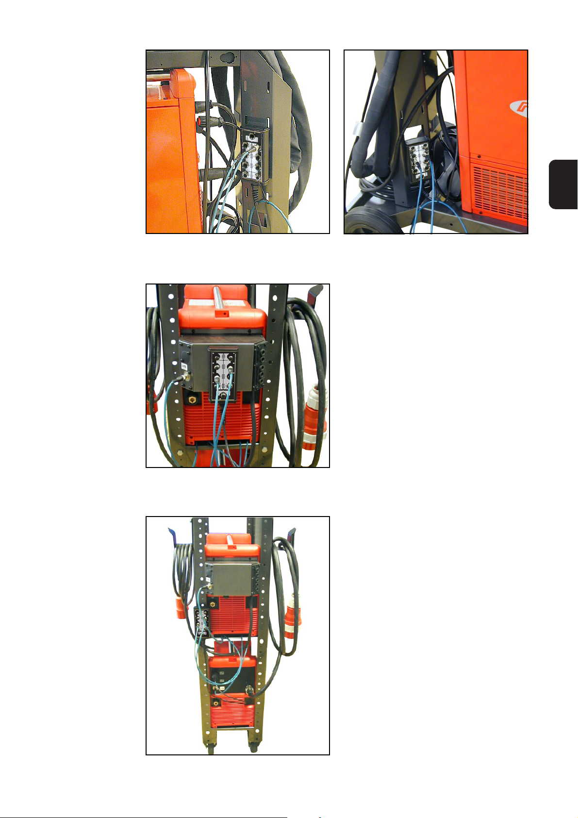
Montage an der
DrahtvorschubAufnahme
Der LHSB-HUB kann auf Grund des Befestigungsmagneten an allen eisenhaltigen
Bauteilen oder Komponenten der Schweißanlage montiert werden.
Im Anschluss finden Sie einige Beispiele von Montagemöglichkeiten.
Drahtvorschub-Aufnahme - Montagemöglichkeit 1
Drahtvorschub-Aufnahme - Montagemöglichkeit 2
Drahtvorschub-Aufnahme - Montagemöglichkeit 3
10
Page 15

Montage an der
GasflaschenHalterung
DE
Montage an der
Unibox
Montage am
Rack für die
Standkonsole
Gasflaschen-Halterung - Montagemöglichkeit 1
Unibox - Montagemöglichkeit 1
Gasflaschen-Halterung - Montagemöglichkeit 2
Rack für Standkonsole - Montagemöglichkeit 1
11
Page 16

Inbetriebnahme
Warnung! Fehlbedienung kann schwerwiegende Personen- und Sachschäden
verursachen. Beschriebene Funktionen erst anwenden, wenn folgende Dokumente vollständig gelesen und verstanden wurden:
- diese Bedienungsanleitung
- sämtliche Bedienungsanleitungen der Systemkomponenten, insbesondere
Sicherheitsvorschriften
Allgemeines
Vorbereitung 1. Schweißanlage aufbauen
2. LHSB-HUB an der Schweißanlage montieren
Maximale Kabellänge
Inbetriebnahme 1. Teilnehmer gemäß Abschnitt „Anschlussbeispiele“ am LHSB-HUB anschließen
Die maximale Kabellänge vom LHSB-HUB zum jeweiligen Teilnehmer darf betragen:
- Bei den Anschlüssen LHSB 1 - 8: max. 20 m
- Beim Anschluss LHSB 9 - Service: max. 100 m
Hinweis! Für optimale Anschluss-Bedingungen beim Anschluss des LHSBHUBs an der Stromquelle den Stecker vom Kabel LocalNet des LHSB-HUBs an
einem Anschluss LocalNet aus Metall an der Stromquelle anschließen (z.B.
Option „Adapter Kunststoff / Metall“ oder Verteiler LocalNet aktiv)
2. Kabel LocalNet vom LHSB-HUB an einer beliebigen Stromquelle anschließen
3. Netzkabel der Stromquelle am Netz anschließen
4. Netzschalter der Stromquelle in Stellung „I“ schalten
5. Status der LHSB-Anschlüsse am LHSB-HUB überprüfen: die jeweiligen LEDAnzeigen müssen grün leuchten
6. Abdeckkappen M12 auf nicht verwendete LHSB-Anschlüsse aufschrauben
12
Page 17

Firmware LHSB-HUB aktualisieren
Warnung! Fehlerhaft durchgeführte Arbeiten können schwerwiegende Sach-
und Personenschäden verursachen. Nachfolgend beschriebene Tätigkeiten
dürfen nur von geschultem Fachpersonal durchgeführt werden! Beachten Sie
die Sicherheitsvorschriften in der Bedienungsanleitung der Stromquelle.
Allgemeines
DE
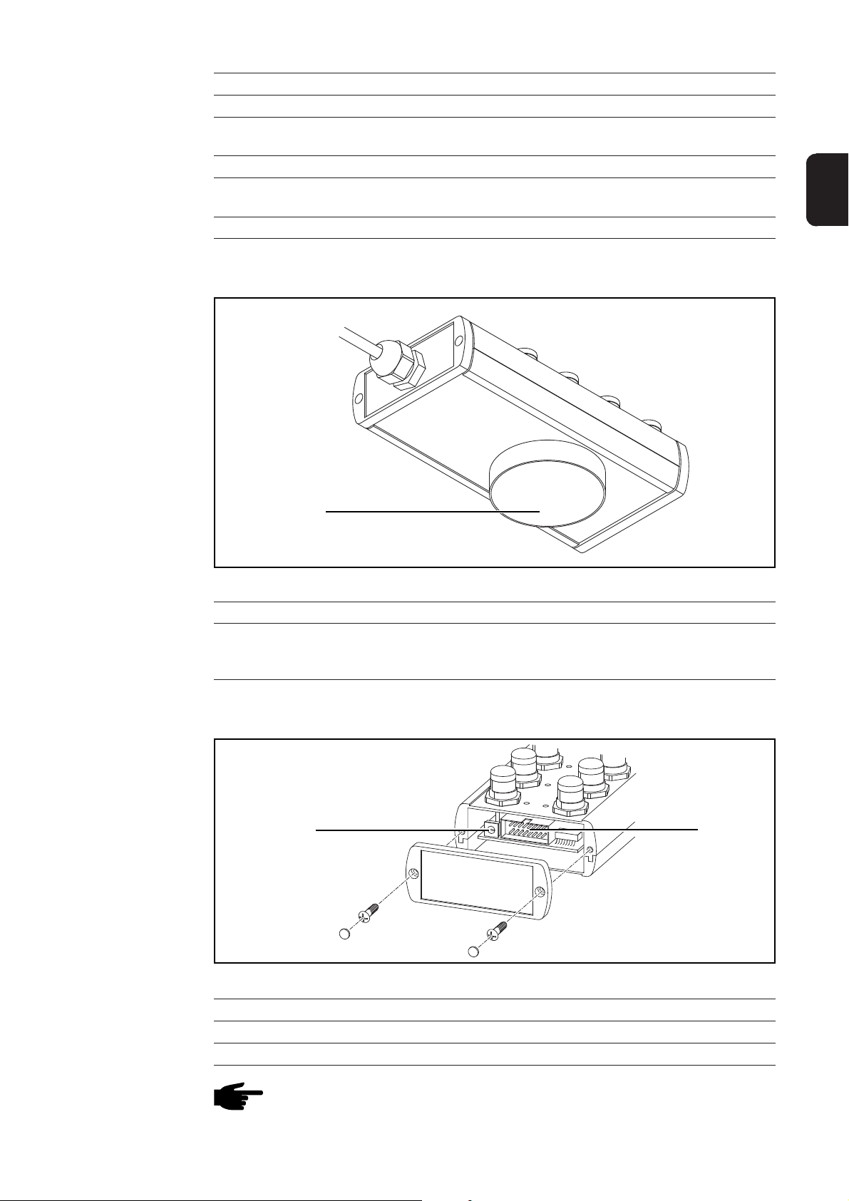
Firmware LHSBHUB aktualisieren
Das Aktualisieren der Firmware LHSB-HUB erfolgt mit dem Fronius BSL-Tool bei aufrechter LocalNet-Verbindung zu einer Stromquelle und bei aufrechter Stromversorgung.
1.
2.
1
2
3
2
4
1
5
0
6
9
7
1
Seitliche Abdeckung entfernen
3.
8
3
2
Flachbandkabel vom BSL-Tool am Anschluss
BSL-Tool anstecken; Firmware aktualisieren
4.
4
3
2
4
1
5
0
6
9
7
8
3
3
2
4
1
5
0
6
9
7
Detail X
3
2
4
1
5
0
6
9
7
8
X
8
1
2
3
max. 1,2 Nm
Flachbandkabel vom BSL-Tool abstecken;
überprüfen, ob der Konfigurations-Wahlschalter auf
Seitliche Abdeckung montieren;
max. Anzugsmoment der Schrauben = 1,2 Nm
Pos. „0“ eingestellt ist
5. Stromquelle ausschalten und wieder einschalten (Stromversorgung zum LHSB-HUB
unterbrechen und wieder herstellen)
13
Page 18

Fehlerdiagnose, Fehlerbehebung
Fehlerdiagnose,
Fehlerbehebung
LED-Anzeigen leuchten rot - Störung in der Verbindung oder der Hardware
Teilnehmer angeschlossen, aufrechte Stromversorgung des LHSB-HUB über eine
Stromquelle.
Ursache: Verbindungskabel defekt, Fehler beim Teilnehmer, Fehler im LHSB-HUB,
etc.
Behebung: defekte Komponenten austauschen
Ursache: Teilnehmer ist bei der betreffenden Anwendung am falschen Anschluss
LHSB ansgeschlossen (z.B. Slave-Stromquelle am Anschluss LHSB für
den Drahtvorschub angeschlossen)
Behebung: Teilnehmer der Anwendung entsprechend richtig anschließen
Ursache: Konfigurations-Wahlschalter ist verstellt
Behebung: Konfigurations-Wahlschalter auf Pos. „0“ einstellen:
- Seitliche Abdeckung entfernen
- Konfigurations-Wahlschalter auf Pos. „0“ einstellen
- Seitliche Abdeckung montieren
- Stromquelle ausschalten und wieder einschalten (Stromversorgung
zum LHSB-HUB unterbrechen und wieder herstellen)
LED-Anzeigen wechseln zwischen orange und grün - Störung in der Verbindung
Teilnehmer angeschlossen, aufrechte Stromversorgung des LHSB-HUB über eine
Stromquelle.
Ursache: Verbindungskabel defekt
Behebung: defekte Verbindungskabel austauschen
Ursache: LHSB-Stecker locker
Behebung: LHSB-Stecker fixieren, gegebenenfalls Verbindungskabel austauschen
Ursache: Verbindungskabel nicht am Anschluss LHSB angeschraubt
Behebung: Verbindungskabel am Anschluss LHSB festschrauben
14
Page 19

Pflege, Wartung und Entsorgung
DE
Allgemeines
Bei jeder Inbetriebnahme
Alle 6 Monate
Entsorgung
Der LHSB-HUB benötigt unter normalen Betriebsbedingungen nur ein Minimum an
Pflege und Wartung. Das Beachten einiger Punkte ist jedoch unerlässlich, um das Gerät
über Jahre hinweg einsatzbereit zu halten.
- Verbindungskabel und Kabel LocalNet auf Beschädigung prüfen
- Gerät mit trockener, reduzierter Druckluft sauberblasen
- Gerät auf mechanische Beschädigung überprüfen
Die Entsorgung nur gemäß den geltenden nationalen und regionalen Bestimmungen
durchführen.
15
Page 20

16
Page 21

Dear Reader
Introduction
Thank you for choosing Fronius - and congratulations on your new, technically highgrade Fronius product! This instruction manual will help you get to know your new
machine. Read the manual carefully and you will soon be familiar with all the many
great features of your new Fronius product. This really is the best way to get the most
out of all the advantages that your machine has to offer.
Please also take special note of the safety rules - and observe them! In this way, you
will help to ensure more safety at your product location. And of course, if you treat your
product carefully, this definitely helps to prolong its enduring quality and reliability - things
which are both essential prerequisites for getting outstanding results.
EN
ud_fr_st_et_00493 01/2012
Page 22

Page 23

Table of Contents
General ......................................................................................................................................................... 2
Terminology .............................................................................................................................................. 2
Technical Specifications ........................................................................................................................... 2
Applications .............................................................................................................................................. 2
System requirements ............................................................................................................................... 2
Scope of delivery and options ....................................................................................................................... 3
Scope of delivery ...................................................................................................................................... 3
Options ..................................................................................................................................................... 3
Control elements, connectors, and mechanical components ........................................................................ 4
General .................................................................................................................................................... 4
Front panel: control elements and connectors ......................................................................................... 4
Rear panel: mechanical components ....................................................................................................... 5
Inside the casing: control elements and connectors ................................................................................ 5
Explanation of LED displays .......................................................................................................................... 6
General .................................................................................................................................................... 6
LED displays not lit ................................................................................................................................... 6
LED displays show orange ....................................................................................................................... 6
LED displays show green ......................................................................................................................... 6
LED displays show red ............................................................................................................................. 6
Connection examples.................................................................................................................................... 7
TimeTwin Digital 7200 / 9000 ................................................................................................................... 7
Powersharing: TS/TPS 7200, TS/TPS 9000 ............................................................................................ 8
TimeTwin Digital 4000 / 5000 ................................................................................................................... 9
EN
Assembly options ........................................................................................................................................ 10
General .................................................................................................................................................. 10
Attaching to wirefeeder bracket.............................................................................................................. 10
Attaching to gas bottle bracket ................................................................................................................ 11
Attaching to the Unibox ...........................................................................................................................11
Attaching to the upright console rack ......................................................................................................11
Commissioning ........................................................................................................................................... 12
General .................................................................................................................................................. 12
Preparation............................................................................................................................................. 12
Maximum cable length ........................................................................................................................... 12
Commissioning ...................................................................................................................................... 12
Updating the LHSB-HUB firmware .............................................................................................................. 13
General .................................................................................................................................................. 13
Updating the LHSB-HUB firmware ......................................................................................................... 13
Troubleshooting and remedying .................................................................................................................. 14
Troubleshooting and remedying ............................................................................................................. 14
Maintenance, servicing, disposal ................................................................................................................ 15
General .................................................................................................................................................. 15
Whenever you use the system ............................................................................................................... 15
Every 6 months ...................................................................................................................................... 15
Disposal ................................................................................................................................................. 15
1
Page 24

General
Terminology LHSB .... LocalNet Highspeed Bus (for high speed data transfer)
HUB ...... A network distribution component for hub and spoke topologies. A HUB rege-
nerates and amplifies the signals it receives and makes these signals available
at all ports. Thus, a HUB allows you for a data exchange between multiple
nodes.
Technical
Specifications
Power supply 24 V DC
Protection type IP 23
Dimensions l / b / h 164 / 85 / 55 mm
6.46 / 3.35 / 2.17 in.
Weight 732 g
1.61 lbs.
Applications
System requirements
LHSB-HUB
The LHSB-HUB is used for high-power welding when more than two power supplies,
“intelligent components“ or devices need to be connected by means of an LHSB.
The LHSB-HUB is suitable for the following processes:
- TimeTwin Digital 7200 / 9000
- Powersharing (TS/TPS 7200 / 9000)
- TimeTwin Digital 4000 / 5000
- CMT (= Cold Metal Transfer)
- LHSB port on each device to be connected
- one connecting cable per device for the LHSB-HUB
- Firmware version OFFICIAL UST V.3.24.54 installed on power sources
2
Page 25

Scope of delivery and options
Scope of delivery
9 x cap M12
1 x LHSB-HUB
incl. fixing magnet
EN
Options
1 x rubber cap for fixing magnet
1 x LocalNet cable incl. strain relief And LocalNet plug
Scope of delivery LHSB-HUB
- LHSB connecting cable 2 m (43,0004,2501)
- LHSB connecting cable 5 m (43,0004,2633)
- LHSB connecting cable 9 m (43,0004,2634)
3
Page 26

Control elements, connectors, and mechanical com-
Warning! Misuse can cause severe injury and damage. Make sure that you
read and understand the following documents, before using the functions
described here:
- this manual
- operating manuals for all the system components, paying special attention
to security rules
ponents
General
Front panel:
control elements
and connectors
(19)
Control elements and connectors, front panel
Item Name Function
(1) Port LHSB 1 For attaching the master power supply
(2) LED display “Port 1“ For status display Port 1
(3) Port LHSB 2 For connecting the slave power supply
(4) LED display “Port 2“ For status display Port 2
(5) Port LHSB 3 For connecting a wirefeeder, for example (with
(6) LED display “Port 3“ For status display Port 3
(7) LED display “Port 4“ For status display Port 4
(8) Port LHSB 4 / 24 V For attaching a device that requires a 24 V DC
(9) LED display “Port 9“ For status display Port 9
(10) Port LHSB 9 - Service Additional Port e.g. for servicing
(11) LocalNet cable Power supply of LHSB-HUB via LocalNet
(12) Port LHSB 8 / 24 V For attaching a device that requires a 24 V DC
(13) LED display “Port 8“ For status display Port 8
(14) Port LHSB 7 For connecting a wirefeeder, for example with
(1)
(18) (17) (16) (15)(14) (13)
4
(10)(9)(8)(7)(6)(5)(4)(3)(2)
(12)
TimeTwin Digital 7200 / 9000 or for Powersharing)
power supply
power supply
TimeTwin Digital 7200 / 9000
(11)
Page 27
Front panel:
control elements
and connectors
(Cont.)
Rear panel:
mechanical
components
Pos. Bezeichnung Funktion
(15) LED display “Port 7“ For status display port 7
(16) Port LHSB 6 E.g. for attaching a second slave power supply
with TimeTwin Digital 7200 / 9000
(17) LED display “Port 6“ For status display port 6
(18) Port LHSB 5 E.g. for attaching a second master power supply
with TimeTwin Digital 7200 / 9000
(19) LED display “Port 5“ For status display connector 5
EN
Inside the casing:
control elements
and connectors
(20)
Mechanical components, rear panel
Item Name Function
(20) Fixing magnet For attaching the LHSB-HUB to magnetic
elements or components (z.B. trolley, upright
console, wirefeeder bracket, etc.)
3
2
4
1
5
0
6
(21) (22)
9
7
8
Control elements and connectors, inside the casing
Item Name Function
(21) Configuration dipswitches For configuring the LHSB ports
(22) Connector for BSL Tool For updating the LHSB-HUB firmware
Note! To enable LHSB-HUB operations, the configuration dipswitch (21) must
be set to Pos. “0“.
5
Page 28

Explanation of LED displays
General The LHSB-HUB has 9 LED displays. An LED display is assigned to each LHSB port.
The LED displays indicate the status of the LHSB port by showing orange, green, or red.
LED displays
not lit
LED displays
show orange
LED displays
show green
Power failure
Cause: The LocalNet cable for the LHSB-HUB is not attached to a power supply
Remedy: Attach the LocalNet cable to a power supply and switch on the power
supply
Cause: LHSB-HUB is faulty
Remedy: Replace LHSB-HUB
Waiting for node to connect
The power supply to the LHSB-HUB is active.
There are no nodes attached to the LHSB ports.
Nodes attached, connection OK
The power supply to the LHSB-HUB is active.
Nodes are attached to the LHSB ports.
The connection to the nodes is ok.
LED displays
show red
Consumer attached, connection or hardware error
The power supply to the LHSB-HUB is active.
Nodes are attached to the LHSB ports.
The connection to the nodes is faulty.
Cause: Connecting cable faulty, node error, LHSB-HUB error, etc.
Remedy: Replace defective components
6
Page 29

Connection examples
TimeTwin Digital
7200 / 9000
FK 9000 R
LHSB-HUB port connections for TimeTwin Digital 7200 / 9000:
LHSB-HUB Port Connected to
LHSB 1 Master power supply 1
LHSB 2 Slave power supply 1
LHSB 3 not attached
LHSB 4 not attached
LHSB 5 Master power supply 2
LHSB 6 Slave power supply 2
LHSB 7 not attached
LHSB 8 not attached
TPS 4000 TPS 4000 Remote
Service
EN
LHSB
LocalNet
Power (-)
Power (+)
Water infeed
Water return line
LHSB-HUB
TPS 4000
Robot Interface
„Twin Standard
I/O Job“
Robot controller
Symmetry regulator
TPS 4000 Remote
FK 9000 R
Symmetry regulator
2 x VR 1500
Job
Connection example TimeTwin Digital 7200 / 9000
7
Page 30

Powersharing:
TS/TPS 7200,
TS/TPS 9000
Robot
Interface
LHSB-HUB port connections for Powersharing:
LHSB-HUB Port Connected to
LHSB 1 Master power supply
LHSB 2 Slave power supply
LHSB 3 not attached
LHSB 4 not attached
LHSB 5 -
LHSB 6 -
LHSB 7 -
LHSB 8 not attached
TPS 4000 TPS 4000 Remote
VR 1500
FK 9000 R
Robot controller
LHSB-HUB
Job
Symmetry regulator
Service
LHSB
LocalNet
Power (-)
Power (+)
Water infeed
Water return line
Connection example Powersharing
8
Page 31

TimeTwin Digital
4000 / 5000
LHSB-HUB port connections for TimeTwin Digital 4000 / 5000:
LHSB-HUB Port Connected to
LHSB 1 Power supply 1
LHSB 2 -
LHSB 3 -
LHSB 4 not attached
LHSB 5 Power supply 2
LHSB 6 -
LHSB 7 -
LHSB 8 not attached
TPS 4000
EN
Robot Interface
„Twin Standard
I/O Job“
Robot controller
LHSB-HUB
TPS 4000 Remote
FK 9000 R
LHSB
Service
2 x VR 1500
Job
LocalNet
Power (-)
Power (+)
Water infeed
Water return line
Connection example TimeTwin Digital 4000 / 5000
9
Page 32

Assembly options
General
Attaching to
wirefeeder bracket
You can using the fixing magnet to attach the LHSB-HUB to any magnetic element or
component of the welding system.
This section shows a few examples of assembly options.
Wirefeeder bracket - assembly option 1
Wirefeeder bracket - assembly option 2
Wirefeeder bracket - assembly option 3
10
Page 33

Attaching to gas
bottle bracket
EN
Attaching to the
Unibox
Attaching to the
upright console
rack
Gas bottle bracket - assembly option1
Unibox - assembly option 1
Gas bottle bracket - assembly option 2
Upright console rack - assembly option 1
11
Page 34

Commissioning
Warning! Misuse can cause severe injury and damage. Make sure that you
read and understand the following documents, before using the functions
described here:
- this manual
- operating manuals for all the system components, paying special attention
to security rules
General
Preparation 1. Set up the welding system
2. Attach the LHSB-HUB to the welding system
Maximum cable
length
Commissioning 1. Attach nodes to LHSB-HUB as shown in section “Connection examples“
The maximum cable length from the LHSB-HUB to the node is:
- For ports LHSB 1 - 8: max. 20 m
- For port LHSB 9 - Service: max. 100 m
Note! For best connection results, plug the LocalNet cable from the LHSB-HUB
into a metal LocalNet port on the power source (e.g. option “Adapter Plastic /
Metal“ or LocalNet switch active)
2. Attach the LHSB-HUB LocalNet cable to any suitable power supply
3. Attach the power supply power cable to the mains
4. Set the mains switch on the power supply to the “I“ position
5. Check the status of the LHSB ports on the LHSB-HUB. Make sure that the LED
displays are showing green
6. Attach M12 caps to any LHSB ports not in use
12
Page 35

Updating the LHSB-HUB firmware
Warning! Failure to perform the tasks described here can cause severe injury
and damage. The work described in the following can be carried out by skilled
personnel trained by Fronius only! Observe the safety rules detailed in the
operating instructions of the power source.
General
EN
Updating the
LHSB-HUB
firmware
To update the LHSB-HUB firmware, you need the BSL Tool, an active LocalNet connection to a power supply, and mains power.
1.
2.
1
2
3
2
4
1
5
0
6
9
7
Remove the side panel
3.
8
3
2
1
Attach the flat BSL Tool cable to the
BSL Tool port; update the firmware
4.
4
3
2
4
1
5
0
6
9
7
8
3
3
2
4
1
5
0
6
9
7
Detail X
3
2
4
1
5
0
6
9
7
8
X
8
1
2
3
max. 1,2 Nm
Remove the BSL Tool flat cable;
check if the configuration dipswitch is set to Pos. “0“
Replace the side panel;
max. tightening torque for screws = 1.2 Nm
5. Switch the power supply off, and back on again (disconnect the power supply to the
LHSB-HUB and restore it)
13
Page 36

Troubleshooting and remedying
Troubleshooting
and remedying
LED displays show red - connection or hardware error
Nodes attached, power supply to LHSB-HUB active.
Cause: Connecting cable faulty, node faulty, LHSB-HUB error, etc.
Remedy: Replace defective components
Cause: Node is attached to wrong LHSB port for the current application (e.g. slave
power supply attached to LHSB port for wirefeeder)
Remedy: Attach the nodes for the application to the correct ports
Cause: Configuration dipswitch in wrong position
Remedy: Set configuration dipswitch to Pos. “0“:
- Remove side panel
- Set configuration dipswitch to Pos. “0“
- Replace side panel
- Switch the power supply off, and back on again (disconnect the
power supply to the LHSB-HUB and restore it)
LED displays continually flash orange and green - faulty connection
Nodes attached, power supply to LHSB-HUB active.
Cause: Connecting cable faulty
Remedy: Replace defective connecting cable
Cause: LHSB plug loose
Remedy: Tighten up LHSB plug, replace connecting cable if needed
Cause: Connecting cable not attached to LHSB port
Remedy: Attach connecting cable to LHSB port
14
Page 37

Maintenance, servicing, disposal
General
Whenever you
use the system
Every 6 months
Disposal
Under normal operating conditions, the LHSB-HUB needs very little maintenance and
servicing work. This said, a few points should be observed to ensure the availability of
the device for several years.
- Check connecting cable and LocalNet cable for signs of damage
- Blow clean the device with dry, low-pressure compressed air
- Check the device for signs of mechanical damage
Observe national and regional laws when disposing of the device.
EN
15
Page 38

16
Page 39

Cher lecteur
Introduction
Nous vous remercions de votre confiance et vous félicitons d’avoir acheté un produit de
qualité supérieure de Fronius. Les instructions suivantes vous aideront à vous familiariser avec le produit. En lisant attentivement les instructions de service suivantes, vous
découvrirez les multiples possibilités de votre produit Fronius. C’est la seule manière
d’exploiter ses avantages de manière optimale.
Prière d’observer également les consignes de sécurité pour garantir une sécurité accrue
lors de l’utilisation du produit. Une utilisation soigneuse du produit contribue à sa longévité et sa fiabilité. Ce sont des conditions essentielles pour obtenir d’excellents résultats.
FR
ud_fr_st_et_00500 01/2012
Page 40

Page 41

Sommaire
Généralités .................................................................................................................................................... 2
Explication des termes employés............................................................................................................. 2
Données techniques ................................................................................................................................ 2
Domaines d´application ............................................................................................................................ 2
Exigences du système ............................................................................................................................. 2
Volume de livraison et options....................................................................................................................... 3
Volume de livraison .................................................................................................................................. 3
Options ..................................................................................................................................................... 3
Eléments de commande, connexions et composants mécaniques .............................................................. 4
Généralités ............................................................................................................................................... 4
Face avant: éléments de commande et connexions ................................................................................ 4
Face arrière: composants mécaniques .................................................................................................... 5
Intérieur du boîtier: éléments de commande et connexions .................................................................... 5
Explication relative aux voyants LED ............................................................................................................ 6
Généralités ............................................................................................................................................... 6
Voyants LED ne s´allument pas ............................................................................................................... 6
Voyants LED oranges allumés ................................................................................................................. 6
Voyants LED verts allumés ...................................................................................................................... 6
Voyants LED rouges allumés ................................................................................................................... 6
Exemples de connexion ................................................................................................................................ 7
TimeTwin Digital 7200 / 9000 ................................................................................................................... 7
Powersharing: TS/TPS 7200, TS/TPS 9000 ............................................................................................ 8
TimeTwin Digital 4000 / 5000 ................................................................................................................... 9
FR
Possibilités de montage .............................................................................................................................. 10
Généralités ............................................................................................................................................. 10
Montage sur le support dévidoir-fil ........................................................................................................ 10
Montage sur le support bouteille de gaz .................................................................................................11
Montage sur Unibox ................................................................................................................................ 11
Montage sur rack pour console ............................................................................................................... 11
Mise en service ........................................................................................................................................... 12
Généralités ............................................................................................................................................. 12
Préparation............................................................................................................................................. 12
Longueur maximale du câble ................................................................................................................. 12
Mise en service ...................................................................................................................................... 12
Actualiser le Firmware LHSB-HUB ............................................................................................................. 13
Généralités ............................................................................................................................................. 13
Actualiser le Firmware LHSB-HUB ........................................................................................................ 13
Diagnostic des erreurs, remèdes ................................................................................................................ 14
Diagnostic des erreurs, remèdes ........................................................................................................... 14
Entretien, maintenance et élimination ......................................................................................................... 15
Généralités ............................................................................................................................................. 15
A chaque mise en service ...................................................................................................................... 15
Tous les 6 mois ...................................................................................................................................... 15
Elimination.............................................................................................................................................. 15
1
Page 42

Généralités
Explication des
termes employés
Données techniques
LHSB .... LocalNet Highspeed Bus (transfert de données à très grande vitesse)
HUB ...... Distributeur dans un réseau à topologie en forme d´étoile. Un HUB régénère et
amplifie les signaux reçus et les met à disposition de toutes les sorties (ports).
Un HUB permet ainsi un échange de données entre différents participants.
Tension d´alimentation 24 V DC
Type de protection IP 23
Dimensions L / l / h 164 / 85 / 55 mm
6,46 / 3,35 / 2,17 in.
Poids 732 g
1,61 lbs.
Domaines
d´application
Exigences du
système
LHSB-HUB
Le LHSB-HUB est employé lors du soudage haute puissance quand plus de deux
générateurs de courant, des „composants intelligents“ ou des appareils doivent être
connectés au moyen de LHSB.
Le LHSB-HUB convient aux procédés suivants:
- TimeTwin Digital 7200 / 9000
- Powersharing (TS/TPS 7200 / 9000)
- TimeTwin Digital 4000 / 5000
- CMT (= Cold Metal Transfer)
- Connexion LHSB à l´appareil respectif
- Câble de connexion par appareil au LHSB-HUB
- Version Firmware OFFICIAL UST V.3.24.54 sur les générateurs de courant
2
Page 43

Volume de livraison et options
Volume de livraison
9 x capuchon protecteur M12
FR
1 x LHSB-HUB
incl. aimant de fixation
Options
1 x capuchon caoutchouc
pour aimant de fixation
1 x câble LocalNet incl. décharge de traction et prise LocalNet
Volume de livraison de LHSB-HUB
- Câble de connexion LHSB de 2 m (43,0004,2501)
- Câble de connexion LHSB de 5 m (43,0004,2633)
- Câble de connexion LHSB de 9 m (43,0004,2634)
3
Page 44

Eléments de commande, connexions et composants
Attention! Toute erreur de manipulation peut occasionner des dommages
matériels ou corporels. N´utiliser les fonctions décrites qu´après avoir entièrement lu et compris les documents suivants:
- cette instruction de service
- toutes les instructions de service des composants du système, plus
particulièrement les consignes de sécurité
mécaniques
Généralités
Face avant:
éléments de
commande et
connexions
(19)
Eléments de commande et connexions, face avant
Pos. Dénomination Fonction
(1) Connexion LHSB 1 pour connecter le générateur de courant maître
(2) Voyant LED „connexion 1“ pour afficher le statut de la connexion 1
(3) Connexion LHSB 2 pour connecter le générateur de courant esclave
(4) Voyant LED „connexion 2“ pour afficher le statut de la connexion 2
(5) Connexion LHSB 3 p.ex. pour la connexion d´un dévidoir-fil (de
(6) Voyant LED „connexion 3“ pour afficher le statut de la connexion 3
(7) Voyant LED „connexion 4“ pour afficher le statut de la connexion 4
(8) Connexion LHSB 4 / 24 V pour connecter un appareil qui demande une
(9) Voyant LED „connexion 9“ pour afficher le statut de la connexion 9
(10) Connexion LHSB 9 - service connexion en plus, p.ex. pour le service
(11) Câble LocalNet pour alimenter en courant LHSB-HUB via
(12) Connexion LHSB 8 / 24 V pour connecter un appareil qui demande une
(13) Voyant LED „connexion 8“ pour afficher le statut de la connexion 8
(14) Connexion LHSB 7 p. ex. pour connecter le deuxième dévidoir-fil de
(1)
(18) (17) (16) (15)(14) (13)
4
(10)(9)(8)(7)(6)(5)(4)(3)(2)
(12)
TimeTwin Digital 7200 / 9000 ou de
Powersharing)
alimentation électrique de 24 V DC
LocalNet
alimentation électrique de 24 V DC
TimeTwin Digital 7200 / 9000
(11)
Page 45

Face avant:
éléments de
commande et
connexions
(suite)
Face arrière:
composants
mécaniques
Pos. Dénomination Fonction
(15) Voyant LED „connexion 7“ pour afficher le statut de la connexion 7
(16) Connexion LHSB 6 p.ex. pour la connexion du deuxième générateur
de courant esclave de TimeTwin Digital 7200/9000
(17) Voyant LED „connexion 6“ pour afficher le statut de la connexion 6
(18) Connexion LHSB 5 p. ex. pour la connexion du deuxième générateur
de courant maître de TimeTwin Digital 7200/9000
(19) Voyant LED „connexion 5“ pour afficher le statut de la connexion 5
FR
Intérieur du
boîtier: éléments
de commande et
connexions
(20)
Composants mécaniques, face arrière
Pos. Dénomination Fonction
(20) Aimant de fixation pour le montage de LHSB-HUB sur des
composants ou des éléments en fer (p.ex. chariot,
console, support dévidoir-fil, etc.)
3
2
4
1
5
0
6
(21) (22)
9
7
8
Eléments de commande et connexions, intérieur du boîtier
Pos. Dénomination Fonction
(21) Commutateur sélecteur de configuration pour configurer les connexions de LHSB
(22) Connexion BSL-Tool pour actualiser le Firmware LHSB-HUB
Note! Pour le fonctionnement de LHSB-HUB, le commutateur sélecteur de
configuration (21) doit être placé en pos. „0“.
5
Page 46

Explication relative aux voyants LED
Généralités 9 voyants LED se trouvent sur LHSB-HUB. A chaque connexion LHSB correspond un
voyant LED.
Ces voyants LED informent sur le statut de la connexion LHSB correspondante à l´aide
des couleurs jaune, vert et rouge.
Voyants LED ne
s´allument pas
Voyants LED
oranges allumés
Voyants LED
verts allumés
Aucune alimentation en courant est présente
Cause: Le câble LocalNet de LHSB-HUB n´est pas connecté à un générateur de
courant
Remède: Connecter le câble LocalNet à un générateur de courant, mettre en circuit
le générateur de courant
Cause: LHSB-HUB est défectueux
Remède: Remplacer LHSB-HUB
Attendre la connexion d´un participant
Alimentation en courant maintenue de LHSB-HUB au moyen d´un générateur de courant.
Aucun participant n´est connecté aux connexions LHSB.
Participant connecté, connexion OK
Alimentation en courant maintenue de LHSB-HUB au moyen d´un générateur de courant.
Participants sont connectés aux connexions LHSB.
La connexion aux participants est en ordre.
Voyants LED
rouges allumés
Participant connecté, perturbation dans la connexion ou le hardware
Alimentation en courant maintenue de LHSB-HUB au moyen d´un générateur de courant.
Participants sont connectés aux connexions LHSB.
La connexion aux participants n´est pas en ordre.
Cause: Câble de connexion défectueux, erreur du participant, erreur de LHSB-
HUB, etc.
Remède: Remplacer les composants défectueux
6
Page 47

Exemples de connexion
TimeTwin Digital
7200 / 9000
FK 9000 R
Occupation des connexions au LHSB-HUB pour TimeTwin Digital 7200 / 9000:
Connexion au LHSB-HUB Occupation
LHSB 1 Générateur de courant maître 1
LHSB 2 Générateur de courant esclave 1
LHSB 3 Libre
LHSB 4 Libre
LHSB 5 Générateur de courant maître 2
LHSB 6 Générateur de courant esclave 2
LHSB 7 Libre
LHSB 8 Libre
TPS 4000 TPS 4000 Remote
service
LHSB
LocalNet
courant (-)
courant (+)
amenée d´eau
retour d´eau
FR
LHSB-HUB
TPS 4000
interface robot
„Twin Standard
I/O Job“
commande robot
bobine de choc
symétrique
TPS 4000 Remote
FK 9000 R
bobine de choc symétrique
2 x VR 1500
pièce à
usiner
Exemple de connexion TimeTwin Digital 7200 / 9000
7
Page 48

Powersharing:
TS/TPS 7200,
TS/TPS 9000
interface
robot
Occupation des connexions au LHSB-HUB pour Powersharing:
Connexion au LHSB-HUB Occupation
LHSB 1 Générateur de courant maître
LHSB 2 Générateur de courant esclave
LHSB 3 Libre
LHSB 4 Libre
LHSB 5 -
LHSB 6 -
LHSB 7 -
LHSB 8 Libre
TPS 4000 TPS 4000 Remote
VR 1500
FK 9000 R
commande robot
LHSB-HUB
pièce à
usiner
bobine de choc
symétrique
service
LHSB
LocalNet
courant (-)
courant (+)
amenée d´eau
retour d´eau
Exemple de connexion Powersharing
8
Page 49

TimeTwin Digital
4000 / 5000
Occupation des connexions au LHSB-HUB pour TimeTwin Digital 4000 / 5000:
Connexion au LHSB-HUB Occupation
LHSB 1 Générateur de courant 1
LHSB 2 -
LHSB 3 -
LHSB 4 Libre
LHSB 5 Générateur de courant 2
LHSB 6 -
LHSB 7 -
LHSB 8 Libre
TPS 4000
FR
interface robot
„Twin Standard
I/O Job“
commande robot
LHSB-HUB
TPS 4000 Remote
FK 9000 R
LHSB
service
2 x VR 1500
pièce à
usiner
LocalNet
courant(-)
courant(+)
amenée d´eau
retour d´eau
Exemple de connexion TimeTwin Digital 4000 / 5000
9
Page 50

Possibilités de montage
Généralités
Montage sur le
support dévidoirfil
Le LHSB-HUB peut être monté, en raison de l´aimant de fixation, sur tous les éléments
ou les composants en fer du poste de soudage.
Vous trouverez à la suite quelques exemples de possibilités de montage.
Support dévidoir-fil - possibilité de montage 1
Support dévidoir-fil - possibilité de montage 2
Support dévidoir-fil - possibilité de montage 3
10
Page 51
Montage sur le
support bouteille
de gaz
FR
Montage sur
Unibox
Montage sur rack
pour console
Support bouteille de gaz - possibilité de montage 1
Unibox - possibilité de montage 1
Support bouteille de gaz - possibilité de montage 2
Rack pour console - possibilité de montage 1
11
Page 52

Mise en service
Attention! Toute erreur de manipulation peut occasionner des dommages
matériels ou corporels. N´utiliser les fonctions décrites qu´après avoir entièrement lu et compris les documents suivants:
- cette instruction de service
- toutes les instructions de service des composants du système, plus
particulièrement les consignes de sécurité
Généralités
Préparation 1. Assembler le poste de soudage
2. Monter LHSB-HUB sur le poste de soudage
Longueur maximale du câble
Mise en service 1. Connecter le participant selon le paragraphe „exemples de connexion“ au LHSB-
La longueur maximale du câble de LHSB-HUB relié au participant correspondant ne doit
pas dépasser:
- Pour les connexions LHSB 1 - 8: max. 20 m
- Pour la connexion LHSB 9 - service: max. 100 m
HUB
Note! Connecter la prise du câble LocalNet de LHSB-HUB à une connexion
LocalNet en métal au générateur de courant afin d´obtenir des conditions
optimales de connexion lors de la connexion de LHSB-HUB au générateur de
courant (p.ex. option „adaptateur plastique / métal“ ou distributeur LocalNet actif)
2. Connecter le câble LocalNet de LHSB-HUB à un générateur de courant
3. Connecter le câble secteur du générateur de courant au secteur
4. Placer l´interrupteur de secteur du générateur de courant en position „I“
5. Contrôler le statut des connexions LHSB au LHSB-HUB: les voyants LED correspondants doivent être allumés verts
6. Visser les capuchons protecteurs M12 sur les connexions LHSB non utilisées
12
Page 53

Actualiser le Firmware LHSB-HUB
Attention! Toute erreur de manipulation peut occasionner des dommages
matériels ou corporels. Seuls les techniciens Fronius qualifiés sont autorisés à
effectuer les opérations décrites ci-après! Respectez les consignes de sécurité
figurant dans le manuel d´utilisation du générateur de courant.
Généralités
FR
Actualiser le
Firmware LHSBHUB
L´actualisation du Firmware LHSB-HUB s´effectue à l´aide de Fronius BSL-Tool lors de
la connexion LocalNet maintenue, à un générateur de courant, et lors de l´alimentation
en courant maintenue.
1.
2.
1
2
3
2
4
1
5
0
6
9
7
Enlever le cache latéral
3.
8
3
2
1
Connecter le câble plat de BSL-Tool à la connexion
BSL-Tool; actualiser le Firmware
4.
4
3
2
4
1
5
0
6
9
7
8
3
Détail X
3
2
4
1
5
0
6
9
7
8
X
Déconnecter le câble plat de BSL-Tool; contrôler si
le commutateur sélecteur de configuration est placé
Monter le cache latéral;
moment max. de serrage des vis = 1,2 Nm
en pos. „0“
5. Mettre hors circuit puis à nouveau en circuit le générateur de courant (interrompre
l´alimentation en courant au LHSB-HUB et la rétablir)
13
max. 1,2 Nm
3
2
4
1
5
0
6
9
7
8
1
2
3
Page 54

Diagnostic des erreurs, remèdes
Diagnostic des
erreurs, remèdes
Voyants LED allumés rouges - perturbation dans la connexion ou le hardware
Participant connecté, LHSB-HUB alimenté en courant au moyen d´un générateur de
courant.
Cause: Câble de connexion défectueux, erreur chez participant, erreur dans LHSB-
HUB, etc.
Remède: Remplacer les composants défectueux
Cause: Participant est connecté à la mauvaise connexion LHSB lors de
l´application en question (p.ex. générateur de courant esclave connecté à
la connexion LHSB pour le dévidoir-fil)
Remède: Connecter en conséquence correctement le participant de l´application
Cause: Commutateur sélecteur de configuration est déréglé
Remède: Placer le commutateur sélecteur de configuration en pos. „0“:
- Enlever le cache latéral
- Placer le commutateur sélecteur de configuration en pos. „0“
- Monter le cache latéral
- Mettre hors circuit puis à nouveau en circuit le générateur de courant (interrompre l´alimentation en courant au LHSB-HUB et la
rétablir)
Les voyants LED changent entre orange et vert - perturbation dans la connexion
Participant connecté, LHSB-HUB alimenté en courant au moyen d´un générateur de
courant.
Cause: Câble de connexion défectueux
Remède: Remplacer les câbles de connexion défectueux
Cause: Prise LHSB lâche
Remède: Fixer la prise LHSB, remplacer le cas échéant le câble de connexion
Cause: Le câble de connexion n´est pas vissé sur la connexion LHSB
Remède: Visser à fond le câble de connexion sur la connexion LHSB
14
Page 55

Entretien, maintenance et élimination
Généralités
A chaque mise en
service
Tous les 6 mois
Elimination
Le LHSB-HUB n´exige, dans des conditions normales de marche, qu´un minimum
d´entretien et de maintenance. Ces quelques points sont cependant absolument à
respecter afin de conserver l´appareil opérationnel durant plusieurs années.
- Vérifier que le câble de connexion et le câble LocalNet ne soient pas endommagés
- Nettoyer l´apapreil en insufflant de l´air sec et à compression réduite
- Vérifier que l´appareil n´ait pas de dommages mécaniques
Effectuer l´élimination conformément aux consignes nationales et régionales en vigueur.
FR
15
Page 56

16
Page 57

FRONIUS INTERNATIONAL GMBH
Froniusplatz 1, A-4600 Wels, Austria
Tel: +43 (0)7242 241-0, Fax: +43 (0)7242 241-3940
E-Mail: sales@fronius.com
www.fronius.com
Under http://www.fronius.com/addresses you will find all addresses
www.fronius.com/addresses
of our Sales & service partners and Locations.
ud_fr_st_so_00082 012011
 Loading...