

Page 1

Installation
instructions
LHSB
LHSB RJ45
Installationsanleitung
DE
Installation instructions
EN
Instructions d'installation
FR
42,0410,1011 004-22042022
Page 2

Page 3

Inhaltsverzeichnis
LHSB-Verbindung 4
LHSB (LocalNet High Speed Bus) 4
Datenübertragung 4
Einsatzgebiet 4
Systemvoraussetzungen für den Betrieb des Einbausets LHSB 4
Unterscheidungsmerkmale Print UST2A und UST2B 5
Bauteile - Einbauset LHSB 5
Bauteile - Einbauset LHSB RJ45 6
Einbauset LHSB und LHSB RJ45 einbauen 7
Sicherheit 7
Vorbereitung 7
Print LHSB am Print UST2A montieren 8
Print LHSB am Print UST2B montieren 9
Mögliche Montagepositionen für die Anschlussbuchsen LHSB und LHSB RJ45 10
Anschlussbuchse LHSB montieren 10
Anschlussbuchse LHSB RJ45 montieren 12
Buchsenkondensatoren einbauen (für Stromquellen bis Seriennummer 13 45 1101) 14
Abschließende Tätigkeiten 15
LHSB RJ45: Stecker zusammenbauen 15
DE
3
Page 4

LHSB-Verbindung
(1)(2)
LHSB (LocalNet
High Speed Bus)
Datenübertragung
Einsatzgebiet LHSB kommt zum Einsatz, wo mehrere Geräte für einen Prozess verknüpft wer-
Die LHSB-Verbindung ist eine Hochfrequenz-Datenverbindung mit 10 MBaud.
LHSB (LocalNet High Speed Bus) basiert physikalisch auf dem bewährten, DCfreien Ethernet-Prinzip. Das zeitgesteuerte LHSB-Protokoll ist speziell auf die
Anforderungen der Fronius-Produkte ausgelegt und auf Prozesse optimiert, die
mit hoher Geschwindigkeit synchron ablaufen.
Die Datenübertragung zwischen zwei Geräten mit dem Einbauset LHSB-Verbindung erfolgt über das Verbindungskabel LHSB.
Einbauset LHSB: das Verbindungskabel LHSB wird separat angeboten.
-
Einbauset LHSB RJ45: das Verbindungskabel LHSB ist im Lieferumfang des
-
Einbausets enthalten.
HINWEIS!
Das Einbauset LHSB und das Einbauset LHSB RJ45 nur in Verbindung mit entsprechendem Verbindungskabel LHSB verwenden.
den. Derzeit ist die LHSB-Verbindung für folgende Prozesse im Einsatz:
TPS 7200, TPS 9000, TS 7200, TS 9000 sowie TP 7200, TP 9000:
-
Parallelschalten zweier Stromquellen zur Erhöhung der Schweißleistung.
TimeTwin Digital:
-
Hochleistungsschweißen mit zwei unabhängig voneinander geregelten
Lichtbögen.
Systemvoraussetzungen für
den Betrieb des
Einbausets
LHSB
Print UST2A - Bestückungsversion „F“
erforderliche Firmware an der
-
Stromquelle: OFFICIAL UST
V3.10.33 und höher
Print UST2A in Bestückungsversi-
-
on „F“ (ab Stromquellen-Seriennummer 13 19 1156 serienmäßig
in den Stromquellen eingebaut)
oder Print UST2B
Der Print UST2A in Bestückungsversion „F“ besitzt keinen zusätzlichen Stecker unterhalb des 6-poligen Molexsteckers (1). Unterhalb des 6-poligen
Molexsteckers (1) befinden sich nur die
Lötstellen (2).
4
Page 5

Unterschei-
(3)
(5) (4)
(b)
(a)
(j)
(i)
(h)
(g)
(f)
(e)
(d)
(c)
dungsmerkmale
Print UST2A und
UST2B
DE
Bauteile - Einbauset LHSB
Print UST2A
Print UST2B
Der Print UST2A hat keine Leiterbahn um die Bohrung (3).
Der Print UST2B ist mit einer Leiterbahn (4) um die Bohrung (5) ausgeführt.
Einbauset LHSB (4,100,386)
2 Taptite-Schrauben M5 x 16 mm
a)
4 Kabelbinder
b)
Aufkleber LHSB
c)
Fächerscheibe A 5,3
d)
Sechskant-Mutter M5
e)
Anschlussbuchse LHSB mit Verbindungskabel
f)
Print LHSB
g)
Messingdistanz lang M4 x 30 mm (bei UST2B)
h)
Kunststoff-Distanz kurz M4 x 10 mm (bei UST2A)
i)
Messingdistanz kurz M4 x 10 mm (bei UST2B)
j)
5
Page 6

Bauteile - Ein-
(b)
(a)
(j)
(i)
(h)
(g)
(d)
(c)
(f)
(o)(n)
(l)
(m)
(e)
(k)(p)
bauset LHSB
RJ45
Einbauset LHSB RJ45 (4,100,514)
RJF-Steckergehäuse
a)
Klemmstück für RJF-Steckergehäuse
b)
Anschlussbuchse LHSB RJ45
c)
2 Sechskant-Muttern M3
d)
Sechskant-Mutter M5
e)
Fächerscheibe A 5,3
f)
2 Fächerscheiben A 3,2
g)
Print LHSB
h)
Verbindungskabel LHSB 2 m
i)
Verbindungskabel LHSB Stromquellen-intern 0,75 m
j)
2 Linsenschrauben M3 x 10 mm
k)
Kunststoff-Distanz kurz M4 x 10 mm (bei UST2A)
l)
Messingdistanz lang M4 x 30 mm (bei UST2B)
m)
Messingdistanz kurz M4 x 10 mm (bei UST2B)
n)
4 Kabelbinder
o)
Abdeckung
p)
Aufkleber LHSB (ohne Abbildung)
q)
6
Page 7

Einbauset LHSB und LHSB RJ45 einbauen
DE
Sicherheit
WARNUNG!
Gefahr durch Fehlbedienung und fehlerhaft durchgeführte Arbeiten.
Schwere Personen- und Sachschäden können die Folge sein.
Alle in diesem Dokument beschriebenen Arbeiten und Funktionen dürfen
▶
nur von technisch geschultem Fachpersonal ausgeführt werden.
Dieses Dokument vollständig lesen und verstehen.
▶
Sämtliche Sicherheitsvorschriften und Benutzerdokumentationen dieses
▶
Gerätes und aller Systemkomponenten lesen und verstehen.
WARNUNG!
Gefahr durch elektrischen Strom.
Schwere Personen- und Sachschäden können die Folge sein.
Vor Beginn der Arbeiten alle beteiligten Geräte und Komponenten ausschal-
▶
ten und von Stromnetz trennen.
Alle beteiligten Geräte und Komponenten gegen Wiedereinschalten sichern.
▶
Nach dem Öffnen des Gerätes mit Hilfe eines geeigneten Messgerätes si-
▶
cherstellen, dass elektrisch geladene Bauteile (beispielsweise Kondensatoren) entladen sind.
VORSICHT!
Vorbereitung
Gefahr von Beschädigung elektronischer Bauteile durch elektrische Entladung.
Sachschäden können die Folge sein.
Bei Austausch und Installation von Komponenten geeignete ESD Schutz-
▶
maßnahmen treffen.
Netzschalter der Stromquelle in Stellung - O - schalten
1
Stromquelle vom Netz trennen
2
Rechtes Seitenteil entfernen
3
7
Page 8

Print LHSB am
(2) (3)(1)
(3) )6()5()4(
Print UST2A
montieren
WICHTIG! Die folgenden Arbeitsschritte gelten ausschließlich für Stromquellen
mit dem Print UST2A. Die Arbeitsschritte für den Print UST2B finden Sie im folgenden Abschnitt „Print LHSB am Print UST2B montieren“.
Flachband-Kabel (1) des Prints
1
LHSB (3) am Print UST2A (2) anstecken.
Flachband-Kabel anstecken
Print LHSB am Print UST2A montieren
Print LHSB (3) auf Print UST2A aufsetzen
2
Print LHSB (3) befestigen:
3
mittels Fächerscheibe A 5,3 (4) und Sechskant-Mutter M5 (5)
-
mittels Kunststoff-Distanz kurz M4 x 10 mm (6)
-
8
Page 9

Print LHSB am
(1) (4)(3)(2)
(7)(3)(5) (6)
Print UST2B
montieren
WICHTIG! Die folgenden Arbeitsschritte gelten ausschließlich für Stromquellen
mit dem Print UST2B. Die Arbeitsschritte für den Print UST2A finden Sie im vorangegangenen Abschnitt „Print LHSB am Print UST2A montieren“.
Kunststoff-Distanz durch Messing-
1
distanz lang M4 x 30 mm (2) ersetzen
Flachband-Kabel (1) des Prints
2
LHSB (3) am Print UST2B (4) anstecken
Flachband-Kabel anstecken
DE
Print LHSB montieren
Print LHSB (3) am Print UST2B aufsetzen
3
Print LHSB (3) befestigen:
4
mittels Fächerscheibe (5) und Sechskant-Mutter (6)
-
mittels Messingdistanz kurz M4 x 10 mm (7)
-
9
Page 10

Mögliche Monta-
(1)
(2)
44,0 mm
(1.73 in.)
64,0 mm
(2.52 in.)
15 mm
(0.59 in.)
31,3 mm
(1.23 in.)
LHSB
LHSB RJ45
3,5 mm
(0.14 in.)
26,97 mm
(1.06 in.)
gepositionen für
die Anschlussbuchsen LHSB
und LHSB RJ45
Montagepositionen für die Anschlussbuchse
LHSB an der Rückseite der Stromquelle
bevorzugte Montageposition
1
alternative Montagepositionen (z.B.
2
falls an der Stromquelle keine
Durchführung rechts oben vorhanden ist)
Anschlussbuchse LHSB montieren
Für Stromquellen ohne Durchführung rechts
oben und bei belegten alternativen Montagepositionen Durchführung anfertigen
Blindabdeckung an der gewünschten Montageposition entfernen.
1
Falls an der Stromquelle keine Durchführung rechts oben vorhanden ist
-
Montagepositionen am Roboterinterface
und wenn die alternativen Montagepositionen belegt sind, Durchführung
gemäß Kapitel „Mögliche Montagepositionen“ anfertigen (schwarze Linien und Bemaßung).
WICHTIG! Für ausreichende Erdung sorgen. Bei nachträglich gefertigter
-
Durchführung den Lack rund um die Durchführung vollständig entfernen, sodass eine vollständige Erdverbindung zwischen Anschlussbuchse
LHSB und Rückseite der Stromquelle besteht.
10
Page 11

(1)
Anschlussbuchse LHSB ausrichten
(2)
(3)
(4)
(5)
(6)
(7)
(6)
(7)
(8)
Anschlussbuchse LHSB von hinten
2
in die gewünschte Montageposition
einsetzen und ausrichten.
WICHTIG! Beim Montieren
-
der Anschlussbuchse LHSB
darauf achten, dass die offene
Seite (1) der Aussparung im
Inneren der Anschlussbuchse
senkrecht nach oben ausgerichtet ist.
Anschlussbuchse LHSB von hinten
3
in die gewünschte Montageposition
einsetzen und ausrichten.
Bei nachträglich gefertigter
-
Durchführung erfolgt die Befestigung der Anschlussbuchse
LHSB mittels Sechskant-Mutter (3). Vor dem Einsetzen der
Anschlussbuchse LHSB Montageplatte (2) entfernen.
Aufkleber LHSB (3) neben der An-
4
schlussbuchse LHSB (4) aufkleben
DE
Anschlussbuchse LHSB montieren
Verbindungskabel anschließen
Verbindungskabel (6) von der An-
5
schlussbuchse LHSB am Print
LHSB (8) anstecken
Verbindungskabel (6) mittels 4 Ka-
6
belbindern (7) fixieren
11
Page 12

Anschlussbuch-
(1b)
(1a)
(2)(3) (4) (5)
(6)(7)(9)(8)(10)
se LHSB RJ45
montieren
Blindabdeckung an der gewünschten Montageposition entfernen.
1
Falls an der Stromquelle keine Durchführung rechts oben vorhanden ist
-
und wenn die alternativen Montagepositionen belegt sind, Durchführung
gemäß Kapitel „Mögliche Montagepositionen“ anfertigen (graue Linien
und Bemaßung).
WICHTIG! Für ausreichende Erdung sorgen. Bei nachträglich gefertigter
-
Durchführung den Lack um die 4 Bohrungen zur Befestigung der Anschlussbuchse LHSB RJ 45 vollständig entfernen, sodass eine vollständige Erdverbindung zwischen Anschlussbuchse LHSB RJ45 und Rückseite
der Stromquelle besteht.
Linkes Seitenteil der Stromquelle
2
entfernen
Linkes Seitenteil der Stromquelle
3
entfernen
WICHTIG! Beim Montieren
-
der Anschlussbuchse LHSB
RJ45 darauf achten, dass Ausnehmung für Steckerzapfen
(1a) und Ausnehmung für die
Kabelfixierung (1b) nach oben
weisen (für Stecker-Codierung
„A“).
Anschlussbuchse LHSB RJ45 für Stecker-Codierung „A“ ausrichten
WICHTIG! Beim Befestigen der Anschlussbuchse LHSB RJ45 (10) Erdverbindung herstellen: Erdungskabel
(5) an der Rückseite befestigen.
Anschlussbuchse LHSB RJ45 montieren
Anschlussbuchse LHSB RJ45 (10) an der gewählten Durchführung montie-
4
ren:
eine Linsenschraube M3 x 10 mm (4) einsetzen
-
eine Fächerscheibe A 3,2 (3) auf die Schraube aufsetzen
-
Erdungskabel (5) auf die Schraube aufsetzen
-
eine Sechskant-Mutter M3 (2) aufschrauben und festziehen
-
zweite Linsenschraube M3 x 10 mm (7) durch die Befestigungsöse der
-
Abdeckung führen
zweite Linsenschraube M3 x 10 mm (7) in die diagonal gegenüberliegende
-
Bohrung einsetzen
zweite Fächerscheibe (8) auf die Schraube aufsetzen
-
zweite Sechskant-Mutter M3 (9) aufschrauben und festziehen
-
12
Page 13

Verbindungskabel LHSB Stromquellen-intern 0,75 m (6) an der Anschluss-
(12)(11) (6)(12) (12)
(10)(13)
5
buchse LHSB RJ45 (10) anstecken
Verbindungskabel LHSB Strom-
6
quellen-intern 0,75 m (6) am Print
LHSB (11) anstecken
Verbindungskabel LHSB Strom-
7
quellen-intern 0,75 m (6) mittels 4
Kabelbindern (12) fixieren
Verbindungskabel am Print LHSB anstecken
Aufkleber LHSB (13) neben der
8
Anschlussbuchse LHSB RJ45 (10)
aufkleben
DE
Aufkleber LHSB aufkleben
13
Page 14

Buchsenkonden-
(2)
(3)
(1)
47 nF
0 Ohm
(4)
(2)
(3)
ohne Schlauch
mit Schlauch
2 Einzelkondensatoren
2 x 2,2 nF
3 x 3,3 Ohm
ohne Schlauch
mit Schlauch
4 Einzelkondensatoren
4 x 2,2 nF
3 x 3,3 Ohm
(5)
(2)
(3)
satoren einbauen
(für Stromquellen bis Seriennummer 13 45
1101)
HINWEIS!
Bis Seriennummer 13 45 1101 ist bei den Stromquellen TPS 4000 / 5000, TS
4000 / 5000 und TP 4000 / 5000 CEL der Einbau von Buchsenkondensatoren
erforderlich.
Die erforderlichen Buchsenkondensatoren finden Sie in der Ersatzteilliste.
Bestehende Buchsenkondensato-
1
ren (1) für Plus- und Minusbuchse
lösen:
am Buchsenstern (3)
-
an der Masseverbindung (2)
-
Neuen Buchsenkondensator für die
2
Plusbuchse (4) anstecken:
am Buchsenstern (3)
-
an der Masseverbindung (2)
-
Neuen Buchsenkondensator für die
3
Minusbuchse (5) anstecken:
am Buchsenstern (3)
-
an der Masseverbindung (2)
-
14
Page 15

Abschließende
(1) (2)
2.
3.
4.
(3) (4)
Tätigkeiten
HINWEIS!
Vor dem Montieren der Seitenteile darauf achten, dass das Verbindungskabel
zwischen Print LHSB und Anschlussbuchse LHSB weder geknickt, eingeklemmt, noch auf Zug belastet werden kann.
Seitenteile der Stromquelle montieren
1
DE
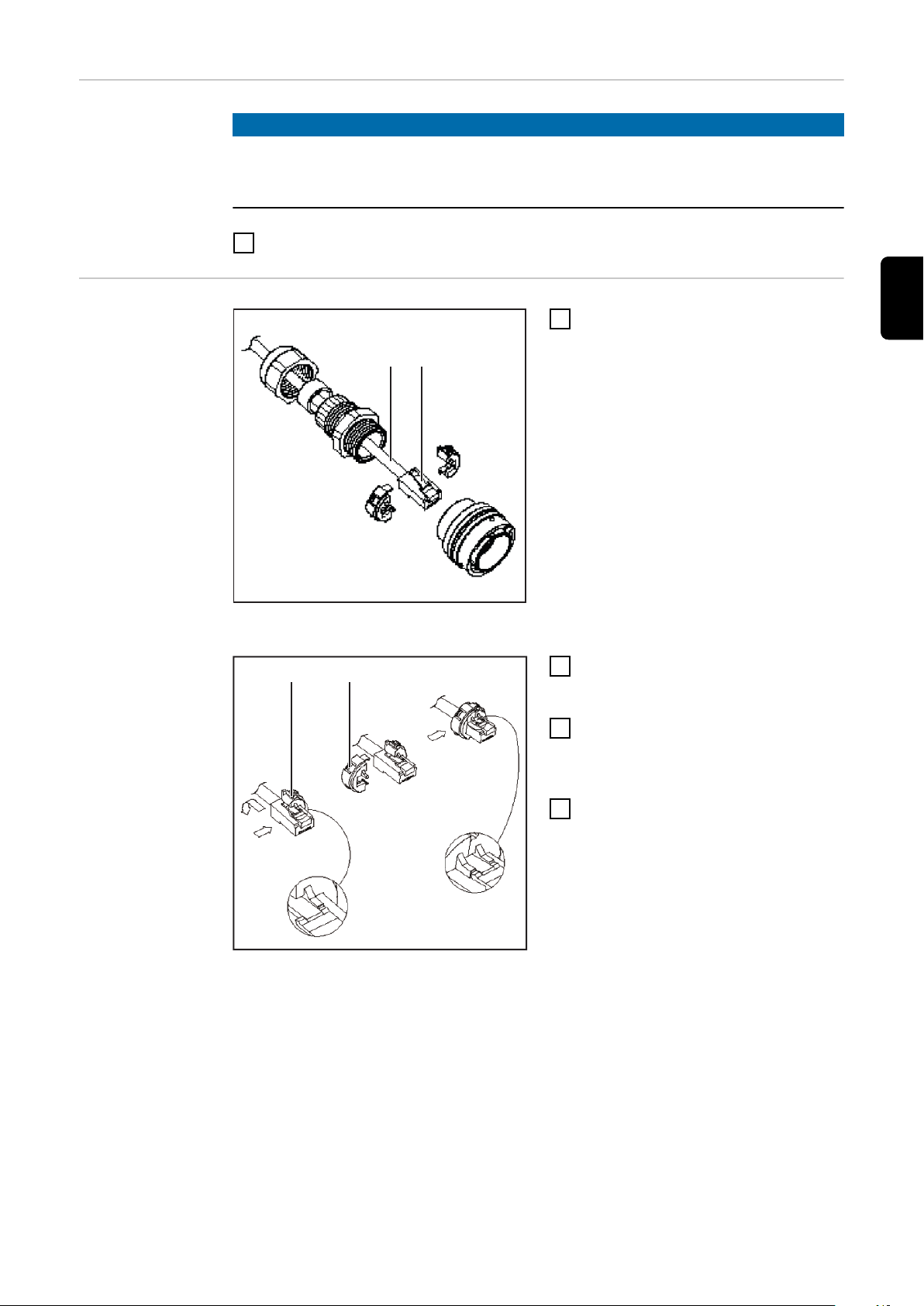
LHSB RJ45: Stecker zusammenbauen
Verbindungskabel LHSB 2 m durch Steckerkomponenten durchführen
Das Verbindungskabel LHSB 2 m
1
(1) durch die Steckerkomponenten
durchführen
Kabelfixierung (2) des Verbin-
2
dungskabels LHSB 2 m nach unten
drücken
Verbindungskabel LHSB 2 m in das
3
halbe Klemmstück für RJF-Steckergehäuse (3) einsetzen
Die zweite Hälfte des
4
Klemmstückes für RJF-Steckergehäuse (4) auf die erste Hälfte des
Klemmstückes klicken
Kabel in Klemmstück für RJF-Steckergehäuse
einsetzen
15
Page 16

(5)
Stecker-Codierung „A“
(2)
Kabel im Steckergehäuse fixieren
WICHTIG! Beim Zusammenbau des
Steckers darauf achten, dass die Kabelfixierung (2) des Verbindungskabels
LHSB 2 m und der Steckerzapfen (5)
gemäß Stecker-Codierung „A“ nach
oben zeigen.
Steckerkomponenten zusammen-
5
schieben und festschrauben
Stecker RJF am Anschluss LHSB
6
RJ45 anschließen
16
Page 17

Contents
LHSB link 18
LHSB (LocalNet High Speed Bus) 18
Data transfer 18
Field of application 18
System requirements for the LHSB installation set 18
Differences between UST2A and UST2B PCBs 19
Components - LHSB installation set 19
Components - LHSB RJ45 installation set 20
Installing the LHSB and LHSB RJ45 installation set 21
Safety 21
Preparations 21
Fitting the LHSB PCB to UST2A PCB 22
Fitting the LHSB PCB to UST2B PCB 23
Possible installation positions for the LHSB and LHSB RJ45 connection sockets 24
Fitting the LHSB connection socket 24
Fitting the LHSB RJ45 connection socket 26
Fitting pillar capacitors (for power sources with serial numbers up to 13 45 1101) 28
Finally... 29
LHSB RJ45: assembling the plug 29
EN
17
Page 18

LHSB link
(1)(2)
LHSB (LocalNet
High Speed Bus)
Data transfer Data is transferred between two devices with the LHSB link installation set via
Field of application
The LHSB link is a high-frequency 10 MBaud data link.
LHSB (LocalNet High Speed Bus) is physically based on the proven DC-free
Ethernet principle. The time-controlled LHSB protocol has been specifically designed for the requirements of Fronius products and optimised for processes
that run synchronously at high speed.
the LHSB cable.
LHSB installation set the LHSB cable is supplied separately.
-
LHSB RJ45 installation set: the LHSB cable is supplied with the installation
-
set.
NOTE!
The LHSB and LHSB RJ45 installation sets should only be used with the corresponding LHSB cable.
LHSB is used where several devices are linked up for one process. At present, the
LHSB link can be used for the following processes:
TPS 7200, TPS 9000, TS 7200, TS 9000 sowie TP 7200, TP 9000:
-
Connecting two power sources in parallel to increase welding power
TimeTwin Digital:
-
High-performance welding with two independently controlled arcs
System requirements for the
LHSB installation set
UST2A PCB - „F“ components set version
required firmware on the power
-
source: OFFICIAL UST V3.10.33
and higher
UST2A PC board in „F“ compon-
-
ents set version (installed in the
power sources as standard from
power source serial number 13 19
1156 upwards) or UST2B PCB
The UST2A PCB in „F“ components
set version does not have an additional
plug below the 6-pin Molex plug (1).
Only brazing joints (2) can be found
below the 6-pin Molex plug (1).
18
Page 19

Differences bet-
(3)
(5) (4)
(b)
(a)
(j)
(i)
(h)
(g)
(f)
(e)
(d)
(c)
ween UST2A and
UST2B PCBs
EN
Components LHSB installation set
UST2A PCB
UST2B PCB
The UST2A PCB has no conductor around the hole (3).
The UST2B PCB has a conductor (4) around the hole (5).
LHSB installation set (4,100,386)
2 M5 x 16 mm Taptite screws
a)
4 cable ties
b)
LHSB sticker
c)
A 5.3 serrated washer
d)
M5 hexagon nut
e)
LHSB connection socket with cable
f)
LHSB PCB
g)
Long M4 x 30 mm brass spacer (on UST2B)
h)
Short M4 x 10 mm plastic spacer (on UST2A)
i)
Short M4 x 10 mm brass spacer (on UST2B)
j)
19
Page 20

Components -
(b)
(a)
(j)
(i)
(h)
(g)
(d)
(c)
(f)
(o)(n)
(l)
(m)
(e)
(k)(p)
LHSB RJ45 installation set
LHSB RJ45 installation set (4,100,514)
RJF plug housing
a)
Clamping piece for RJF plug housing
b)
LHSB RJ45 connection socket
c)
2 M3 hexagon nuts
d)
M5 hexagon nut
e)
A 5.3 serrated washer
f)
2 A 3.2 serrated washers
g)
LHSB PCB
h)
LHSB cable 2 m
i)
Internal power source LHSB cable 0.75 m
j)
2 M3 x 10 mm cheese-head screws
k)
Short M4 x 10 mm plastic spacer (on UST2A)
l)
Long M4 x 30 mm brass spacer (on UST2B)
m)
Short M4 x 10 mm brass spacer (on UST2B)
n)
4 cable ties
o)
Cover
p)
LHSB sticker (not shown)
q)
20
Page 21

Installing the LHSB and LHSB RJ45 installation
set
Safety
WARNING!
Danger from incorrect operation and work that is not carried out properly.
This can result in serious personal injury and damage to property.
All the work and functions described in this document must only be carried
▶
out by technically trained and qualified personnel.
Read and understand this document in full.
▶
Read and understand all safety rules and user documentation for this device
▶
and all system components.
WARNING!
Danger from electrical current.
This can result in serious personal injury and damage to property.
Before starting work, switch off all devices and components involved and dis-
▶
connect them from the grid.
Secure all devices and components involved so they cannot be switched back
▶
on.
After opening the device, use a suitable measuring instrument to check that
▶
electrically charged components (such as capacitors) have been discharged.
CAUTION!
EN
Preparations
Danger of damage to electrical components from electrical discharge.
This can result in damage to property.
Suitable measures should be taken to protect against ESD when replacing
▶
and installing components.
Switch the power source mains switch to the „O“ position
1
Unplug power source from the mains
2
Remove the right side panel
3
21
Page 22

Fitting the LHSB
(2) (3)(1)
(3) )6()5()4(
PCB to UST2A
PCB
IMPORTANT! The following steps apply exclusively to power sources with the
UST2A PCB. The steps for the UST2B PCB can be found in the following section
„Fitting the LHSB PCB to UST2B PCB“.
Connect ribbon cable (1) on LHSB
1
PCB (3) to UST2A PCB (2).
Connecting the ribbon cable
Fitting the LHSB PCB to UST2A PCB
Place the LHSB PCB (3) onto the UST2A PCB
2
Fasten LHSB PCB (3) in place:
3
using A 5.3 serrated washer (4) and M5 hexagon nut (5)
-
and M4 x 10 mm short plastic spacer (6)
-
22
Page 23

Fitting the LHSB
(1) (4)(3)(2)
(7)(3)(5) (6)
PCB to UST2B
PCB
IMPORTANT! The following steps apply exclusively to power sources with the
UST2B PCB. The steps for the UST2A PCB can be found in the previous section
„Fitting the LHSB PCB to UST2A PCB“.
Replace plastic spacer with long
1
M4 x 30 mm brass spacer (2)
Connect ribbon cable (1) on LHSB
2
PCB (3) to UST2B PCB (4)
Connecting the ribbon cable
EN
Print LHSB montieren
Place the LHSB PCB (3) onto the UST2B PCB
3
Fasten LHSB PCB (3) in place:
4
using serrated washer (5) and hexagon nut (6)
-
and M4 x 10 mm short brass spacer (7)
-
23
Page 24

Possible installa-
(1)
(2)
44,0 mm
(1.73 in.)
64,0 mm
(2.52 in.)
15 mm
(0.59 in.)
31,3 mm
(1.23 in.)
LHSB
LHSB RJ45
3,5 mm
(0.14 in.)
26,97 mm
(1.06 in.)
tion positions for
the LHSB and
LHSB RJ45 connection sockets
Installation positions for the LHSB connection
socket on the rear of the power source
Preferred installation position
1
alternative installation positions
2
(e.g. if there is no bushing on the
top right of the power source)
Fitting the LHSB
connection socket
Making a bushing on power sources with no bushing on the top right, and which has no alternative installation positions available
Remove the blanking cover from the desired installation position
1
If there is no bushing on the top right of the power source and there is no
-
Installation positions on the robot interface
alternative installation position, create a bushing as shown in the previous
section “Possible installation positions” (black lines and measurements).
IMPORTANT! Ensure adequate earthing. If the bushing needs to be crea-
-
ted, completely remove the paint from around the bushing to enable a
complete earth connection between the LHSB connection socket and
the rear of the power source.
24
Page 25

(1)
Aligning the LHSB connection socket
(2)
(3)
(4)
(5)
(6)
(7)
(6)
(7)
(8)
Insert the LHSB connection socket
2
from the rear into the desired installation position and align.
IMPORTANT! When fitting the
-
LHSB connection socket, ensure that the open side (1) of
the cut-out in the inside of the
connection socket is vertical.
Fit LHSB connection socket (6) to
3
the chosen bushing using 2 Taptite
M5 x 16 mm screws (4) and (7)
If a bushing is not already
-
available and needs to be created, the LHSB connection socket is fastened using a hexagon nut (3). Before inserting
the LHSB connection socket,
remove mounting plate (2)
Stick LHSB sticker (3) next to the
4
LHSB connection socket (4)
EN
Fitting the LHSB connection socket
Connecting cable
Plug cable (6) on the LHSB con-
5
nection socket into the LHSB PCB
(8)
Fix cable (6) in place using 4 cable
6
ties (7)
25
Page 26

Fitting the LHSB
(1b)
(1a)
(2)(3) (4) (5)
(6)(7)(9)(8)(10)
RJ45 connection
socket
Remove the blanking cover from the desired installation position
1
If there is no bushing on the top right of the power source and there is no
-
alternative installation position, create a bushing as shown in the previous
section “Possible installation positions” (grey lines and measurements).
IMPORTANT! Ensure adequate earthing. If the bushing needs to be crea-
-
ted, completely remove the paint from around the 4 holes used to attach
the LHSB RJ 45 connection socket in order to obtain a satisfactory earth
connection between the LHSB RJ45 connection socket and the rear of
the power source.
Remove the left side panel from
2
the power source
Insert the LHSB RJ45 connection
3
socket from the rear into the desired installation position and align.
IMPORTANT! When fitting the
-
LHSB RJ45 connection socket,
ensure that the recess for the
centre spigot (1a) and the recess for the cable release tab
(1b) point upwards (for plug
coding „A“).
Aligning the LHSB RJ45 connection socket for
plug coding „A“
IMPORTANT! Make an earth connection when fastening the LHSB RJ45
connection socket (10): fasten earth
cable (5) to the rear.
Fitting the LHSB RJ45 connection socket
Fit LHSB RJ45 connection socket (10) to the chosen bushing:
4
Insert 1 M3 x 10 mm cheese-head screw (4)
-
Place 1 A 3.2 serrated washer (3) onto the screw
-
Place earth cable (5) onto the screw
-
Screw on 1 M3 hexagon nut (2) and tighten
-
Insert second M3 x 10 mm cheesehead screw (7) through the securing
-
eye of the cover
Insert second M3 x 10 mm cheesehead screw (7) into the hole diagonally
-
opposite
Place second serrated washer (8) onto the screw
-
Screw on second hexagon M3 nut (9) and tighten
-
Plug 0.75 m LHSB cable (6) inside the power source into the LHSB RJ45
5
connection socket (10)
26
Page 27

(12)(11) (6)(12) (12)
Plugging the cable into the LHSB PCB
(10)(13)
Plug 0.75 m LHSB cable (6) inside
6
the power source into the LHSB
PCB (11)
Fix 0.75 m LHSB cable (6) inside
7
the power source in place using 4
cable ties (12)
Stick LHSB sticker (13) next to the
8
LHSB RJ45 connection socket (10)
EN
Affixing the LHSB sticker
27
Page 28

Fitting pillar ca-
(2)
(3)
(1)
47 nF
0 Ohm
(4)
(2)
(3)
no hose
with hose
2 single capacitors
2 x 2.2 nF
3 x 3.3 Ohm
no hose
with hose
4 single capacitors
4 x 2.2 nF
3 x 3.3 Ohm
(5)
(2)
(3)
pacitors (for
power sources
with serial numbers up to 13 45
1101)
NOTE!
For TPS 4000/5000, TS 4000/5000 and TP 4000/5000 CEL power sources with
serial numbers up to 13 45 1101, pillar capacitors must be installed.
The required pillar capacitors can be found in the spare parts list.
Remove existing pillar capacitors
1
(1) for plus and minus socket:
on the star (3)
-
on the earth connection (2)
-
Connect new pillar capacitor for
2
the plus socket (4):
on the star (3)
-
on the earth connection (2)
-
28
Connect new pillar capacitor for
3
the minus socket (5):
on the star (3)
-
on the earth connection (2)
-
Page 29

Finally...
(1) (2)
2.
3.
4.
(3) (4)
NOTE!
Before fitting the side panels, ensure that the cable between the LHSB PCB and
LHSB connection socket cannot be kinked, trapped, or strained.
LHSB RJ45: assembling the
plug
Fit side panels to the power source
1
Feeding 2 m LHSB cable through plug components
Feed the 2 m LHSB cable (1)
1
through the plug components
Press down the cable release tab
2
(2) on the 2 m LHSB cable
Insert 2 m LHSB cable into the
3
half clamping piece for RJF plug
housing (3)
Click the second half of the clam-
4
ping piece for RJF plug housing (4)
onto the first half of the clamping
piece
EN
Inserting cable into clamping piece for RJF plug
housing
29
Page 30

(5)
Plug coding „A“
(2)
Fixing cable in the plug housing
IMPORTANT! When assembling the
plug, ensure that the cable release tab
(2) on the 2 m LHSB cable and the
centre spigot (5) are pointing upwards
according to plug coding „A“.
Push plug components together
5
and screw tight
Plug RJF plug into LHSB RJ45
6
connection (5) Plug coding „A“
30
Page 31

Sommaire
Liaison LHSB 32
LHSB (LocalNet High Speed Bus) 32
Transmission de données 32
Domaine d’utilisation 32
Configuration du système pour le fonctionnement du kit d’installation LHSB 32
Caractéristiques de différenciation Print UST2A et UST2B 33
Eléments - Kit d’installation LHSB 33
Eléments - Kit d’installation LHSB RJ45 34
Montage du kit d’installation LHSB et LHSB RJ45 35
Sécurité 35
Préparation 35
Montage de Print LHSB sur Print UST2A 36
Montage de Print LHSB sur Print UST2B 37
Positions de montage possibles pour les douilles de connexion LHSB et LHSB RJ45 38
Montage de la douille de raccordement LHSB 38
Montage de la douille de connexion LHSB RJ45 40
Montage des condensateurs de douille (pour sources de courant jusqu’au numéro de série
13 45 1101)
Étapes finales 43
LHSB RJ45 : Assembler le connecteur 43
FR
42
31
Page 32

Liaison LHSB
(1)(2)
LHSB (LocalNet
High Speed Bus)
Transmission de
données
Domaine d’utilisation
La liaison LHSB est une liaison de données haute fréquence à 10 MBaud.
Le LHSB (LocalNet High Speed Bus) se fonde physiquement sur le principe
Ethernet sans DC. Le protocole LHSB à commande temporisée est spécialement
conçu pour les exigences des produits Fronius et optimisé pour des processus se
déroulant à haute vitesse de manière synchrone.
La transmission de données entre deux appareils avec le kit d’installation liaison
LHSB s’effectue par le câble de raccordement LHSB.
Kit d’installation LHSB : le câble de raccordement LHSB est proposée
-
séparément.
Kit d’installation LHSB RJ45 : le câble de liaison LHSB fait partie de la livrai-
-
son du kit d’installation.
REMARQUE!
Utiliser le kit d’installation LHSB et le kit d’installation LHSB RJ45 uniquement
en association avec le câble de raccordement correspondant LHSB.
Le LHSB est utilisé lorsque plusieurs appareils sont interconnectés pour un processus. La connexion LHSB est actuellement utilisée pour les processus suivants :
TPS 7200, TPS 9000, TS 7200, TS 9000 sowie TP 7200, TP 9000 :
-
Montage en parallèle de deux sources de courant pour augmenter la puissance de soudage
TimeTwin Digital :
-
Soudage haute puissance avec deux arcs électriques réglés indépendamment
l’un de l’autre
Configuration du
système pour le
fonctionnement
du kit d’installation LHSB
32
Print UST2A - version d’équipement „F“
microprogramme nécessaire à la
-
source de courant : OFFICIAL
UST V3.10.33 et supérieur
Print UST2A en version d’équipe-
-
ment „F“ (à partir du numéro de
série de source de courant 13 19
1156 monté en série dans les
sources de courant) ou Print UST2B
Le Print UST2A en version d’équipement „F“ ne comporte pas de connecteur supplémentaire sous le connecteur Molex à 6 pôles (1). Sous le connecteur Molex (1) à 6 pôles se trouvent
uniquement les points de brasage (2).
Page 33

Caractéristiques
(3)
(5) (4)
(b)
(a)
(j)
(i)
(h)
(g)
(f)
(e)
(d)
(c)
de différenciation Print UST2A
et UST2B
FR
Eléments - Kit
d’installation
LHSB
Print UST2A
Print UST2B
Le Print UST2A ne comprte pas de piste conductive autour du perçage (3).
Le Print UST2B comporte une piste conductive (4) autour du perçage (5).
Kit d’installation LHSB (4,100,386)
2 vis Taptite M5 x 16 mm
a)
4 attache-câbles
b)
Autocollant LHSB
c)
Rondelle en éventail A 5,3
d)
Écrou hexagonal M5
e)
Douille de connexion LHSB avec câble de liaison
f)
Print LHSB
g)
Pièce d’écartement longue en laiton M4 x 30 mm (pour UST2B)
h)
Pièce d’écartement courte en plastique M4 x 10 mm (pour UST2A)
i)
Pièce d’écartement courte en laiton M4 x 10 mm (pour UST2B)
j)
33
Page 34

Eléments - Kit
(b)
(a)
(j)
(i)
(h)
(g)
(d)
(c)
(f)
(o)(n)
(l)
(m)
(e)
(k)(p)
d’installation
LHSB RJ45
Kit d’installation LHSB RJ45 (4,100,514)
Boîtier de connecteur RJF
a)
Pièce de serrage pour boîtier de connecteur RJF
b)
Douille de connexion LHSB RJ45
c)
2 écrous hexagonaux M3
d)
Écrou hexagonal M5
e)
Rondelle en éventail A 5,3
f)
2 rondelles en éventail A 3,2
g)
Print LHSB
h)
Câble de raccordement LHSB 2 m
i)
Câble de raccordement LHSB sources de courant-interne 0,75 m
j)
2 vis à tête bombée M3 x 10 mm
k)
Pièce d’écartement courte en plastique M4 x 10 mm (pour UST2A)
l)
Pièce d’écartement longue en laiton M4 x 30 mm (pour UST2B)
m)
Pièce d’écartement courte en laiton M4 x 10 mm (pour UST2B)
n)
4 attache-câbles
o)
Cache
p)
Autocollant LHSB (sans illustration)
q)
34
Page 35

Montage du kit d’installation LHSB et LHSB RJ45
Sécurité
AVERTISSEMENT!
Danger dû à une erreur de manipulation et d'erreur en cours d'opération.
Cela peut entraîner des dommages corporels et matériels graves.
Toutes les fonctions et tous les travaux décrits dans le présent document
▶
doivent uniquement être exécutés par du personnel techniquement qualifié.
Ce document doit être lu et compris dans son intégralité.
▶
Lire et comprendre toutes les consignes de sécurité et la documentation uti-
▶
lisateur de cet appareil et de tous les composants périphériques.
AVERTISSEMENT!
Risque d'électrocution.
Cela peut entraîner des dommages corporels et matériels graves.
Avant d'entamer les travaux, déconnecter tous les appareils et composants
▶
concernés et les débrancher du réseau électrique.
S'assurer que tous les appareils et composants concernés ne peuvent pas
▶
être remis en marche.
Après ouverture de l'appareil, s'assurer, à l'aide d'un appareil de mesure ap-
▶
proprié, que les composants à charge électrique (condensateurs, par ex.)
sont déchargés.
FR
Préparation
ATTENTION!
Risque de dommage pour les composants électroniques en raison des décharges
électriques.
Cela peut entraîner des dommages matériels.
Appliquer les mesures de sécurité contre les décharges électrostatiques ap-
▶
propriées lors du remplacement et de l’installation des composants.
Placer l’interrupteur secteur de la source de courant en position - O -.
1
Débrancher la prise secteur de la source de courant
2
Retirer l’élément latéral droit
3
35
Page 36

Montage de Print
(2) (3)(1)
(3) )6()5()4(
LHSB sur Print
UST2A
IMPORTANT! Les étapes suivantes valent exclusivement pour les sources de
courant avec le Print UST2A. Les étapes pour le Print UST2B sont présentées
dans le paragraphe „Montage du Print LHSB sur le Print UST2B“.
Brancher le câble plat (1) du Print
1
LHSB (3) au Print UST2A (2)
Brancher le câble plat
Montage de Print LHSB sur Print UST2A
Disposer Print LHSB (3) sur Print UST2A
2
Fixer Print LHSB (3) :
3
avec une rondelle en éventail A 5,3 (4) et un écrou hexagonal M5 (5)
-
avec une pièce d’écartement courte en plastique M4 x 10 mm (6)
-
36
Page 37

Montage de Print
(1) (4)(3)(2)
(7)(3)(5) (6)
LHSB sur Print
UST2B
IMPORTANT! Les étapes suivantes valent exclusivement pour les sources de
courant avec le Print UST2AB Les étapes pour le Print UST2B sont présentées
dans le paragraphe précédent „Montage du Print LHSB sur le Print UST2B“.
Remplacer la pièce d’d’écartement
1
en plastique par une pièce d’écartement longue en laiton M4 x 30
mm (2)
Brancher le câble plat (1) du Print
2
LHSB (3) au Print UST2B (4)
Brancher le câble plat
FR
Montage de Print LHSB
Disposer Print LHSB (3) sur Print UST2B
3
Fixer Print LHSB (3) :
4
avec une rondelleen éventail (5) et un écrou hexagonal (6)
-
avec une pièce d’écartement courte en laiton M4 x 10 mm (7)
-
37
Page 38

Positions de
(1)
(2)
44,0 mm
(1.73 in.)
64,0 mm
(2.52 in.)
15 mm
(0.59 in.)
31,3 mm
(1.23 in.)
LHSB
LHSB RJ45
3,5 mm
(0.14 in.)
26,97 mm
(1.06 in.)
montage possibles pour les
douilles de connexion LHSB et
LHSB RJ45
Positions de montage pour la douille de connexion LHSB à la face arrière de la source de courant
position de montage préférentielle
1
positions de montage alternatives
2
(p. ex. si la source de courant ne
comporte pas de traversée en haut
à droite)
Montage de la
douille de raccordement
LHSB
Réaliser une traversée pour les sources de courant qui ne comporte pas de traversée en haut à
droite et pour les positions de montage alternatives occupées.
Retirer le cache à la position de montage souhaitée
1
Si la source de courant ne comporte pas de traversée en haut à droite et
-
Positions de montage à l’interface du robot
si les positions de montage alternatives sont occupées, réaliser la traversée comme décrit dans le paragraphe précédent „Positions de montage possibles“ (lignes et cotes noires).
IMPORTANT! Assurer une mise à la terre suffisante. En cas de traversée
-
réalisée ultérieurement, éliminer complètement la peinture autour de la
traversée, de manière à assurer un raccordement complet à la terre entre
la douille de connexion LHSB et la face arrière de la source de courant.
38
Page 39

(1)
Ajustement de la douille de raccordement LHSB
(2)
(3)
(4)
(5)
(6)
(7)
(6)
(7)
(8)
Placer la douille de connexion
2
LHSB par l’arrière dans la position
de montage souhaitée et l’ajuster
IMPORTANT! Lors du montage
-
de la douille de connexion
LHSB, veiller à ce que le côté
ouvert (1) de l’évidement à
l’intérieur de la douille de raccordement soit dirigé verticalement vers le haut.
Monter la douille de raccordement
3
LHSB (6) à la traversée sélectionnée avec 2 vis Taptite M5 x 16
mm (4) et (7)
Dans le cas d’une traversée
-
réalisée ultérieurement, la
douille de connexion LHSB est
fixée avec un écrou hexagonal
(3). Retirer la plaque de montage (2) avant la mise en place de
la douille de connexion LHSB
Coller l’autocollant LHSB (3) à
4
côté de la douille de connexion
LHSB (4)
FR
Montage de la douille de raccordement LHSB
Branchement du câble de raccordement
Enficher le câble de raccordement
5
(6) de la douille de connexion
LHSB au Print LHSB (8)
Fixer le câble de raccordement (6)
6
avec 4 attache-câbles (7)
39
Page 40

Montage de la
(1b)
(1a)
(2)(3) (4) (5)
(6)(7)(9)(8)(10)
douille de connexion LHSB
RJ45
Retirer le cache à la position de montage souhaitée
1
Si la source de courant ne comporte pas de traversée en haut à droite et
-
si les positions de montage alternatives sont occupées, réaliser la traversée comme décrit dans le paragraphe précédent „Positions de montage possibles“ (lignes et cotes grises).
IMPORTANT! Assurer une mise à la terre suffisante. En cas de traversée
-
réalisée ultérieurement, éliminer totalement la peinture autour des 4
perçages pour la fixation de la douille de connexion LHSB RJ 45, de manière à assurer un raccordement à la terre complet entre la douille de
connexion LHSB RJ45 et la face arrière de la source de courant.
Retirer le panneau latéral gauche
2
de la source de courant.
Placer la douille de connexion
3
LHSB RJ45 par l’arrière dans la
position de montage souhaitée et
l’ajuster
-
IMPORTANT! Lors du montage
de la douille de connexion
LHSB RJ45, veiller à ce que
l’évidemment pour le tenon du
connecteur (1a) et l’évidement
destiné à la fixation du câble
(1b) soient dirigés vers le haut
(pour codage de connecteur
„A“).
Ajustement de la douille de connexion LHSB
RJ45 pour le codage de connecteur „A“
IMPORTANT! Raccordement à la terre
lors de la fixation de la douille de connexion LHSB RJ45 (10) : fixer le câble
de terre (5) à la face arrière.
Montage de la douille de connexion LHSB RJ45
Montage de la douille de connexion LHSB RJ45 (10) à la traversée choisie :
4
insérer une vis à tête bombée M3 x 10 mm (4)
-
placer une rondelle en éventail A 3,2 (3) sur la vis
-
disposer le câble de terre (5) sur la vis
-
visser et bloquer un écrou hexagonal
-
inserer la deuxième vis à tête bombée M3 x 10 mm (7) dans le trou de
-
fixation de la cache
insérer la deuxième vis à tête bombée M3 x 10 mm (7) dans le perçage
-
diagonalement opposé
disposer la deuxième rondelle en éventail (8) sur la vis
-
visser et bloquer le deuxième écrou hexagonal M3 (9)
-
40
Page 41

Raccorder le câble de raccordement LHSB sources de courant-interne 0,75
(12)(11) (6)(12) (12)
(10)(13)
5
m (6) à la douille de connexion LHSB RJ45 (10)
Raccorder le câble de raccorde-
6
ment LHSB sources de courant-interne 0,75 m (6) au Print LHSB
(11)
Fixer le câble de raccordement
7
LHSB sources de courant-interne
0,75 m (6) avec 4 attache-câbles
(12)
Brancher le câble de raccordement au Print
LHSB
Coller l’autocollant LHSB (13) à
8
côté de la douille de connexion
LHSB RJ45 (10)
FR
Collage de l’autocollant LHSB
41
Page 42

Montage des
(2)
(3)
(1)
47 nF
0 Ohm
(4)
(2)
(3)
sans tuyau
flexible
avec tuyau flexible
2 condensateurs individuels
2 x 2,2 nF
3 x 3,3 Ohm
sans tuyau
flexible
avec tuyau flexible
4 condensateurs individuels
4 x 2,2 nF
3 x 3,3 Ohm
(5)
(2)
(3)
condensateurs
de douille (pour
sources de courant jusqu’au
numéro de série
13 45 1101)
REMARQUE!
Jusqu’au numéro de série 13 45 1101, le montage de condensateurs de douille
est nécessaire pour les sources de courant TPS 4000 / 5000, TS 4000 / 5000 et
TP 4000 / 5000 CEL.
Les condensateurs nécessaires sont présentés dans la nomenclature des pièces
de rechange.
Desserrer les condensateurs (1)
1
pour douille positive et négative :
à l’étoile de douille (3)
-
au raccordement de masse (2)
-
Brancher le nouveau condensateur
2
pour la douille positive (4)
à l’étoile de douille (3)
-
au raccordement de masse (2)
-
Nouveau condensateur pour la
3
douille négative (5)
à l’étoile de douille (3)
-
au raccordement de masse (2)
-
42
Page 43
Étapes finales
(1) (2)
2.
3.
4.
(3) (4)
REMARQUE!
Avant de monter les éléments latéraux, veiller à ce que le câble de raccordement entre Print LHSB et la douille de connexion LHSB ne puisse pas être
flambé, coincé et ne subisse pas de traction.
Monter les éléments latéraux de la source de courant
1
LHSB RJ45 : Assembler le connecteur
Passage du câble de raccordement LHSB 2 m à
travers les composants du connecteur
Passer le câble de raccordement
1
LHSB 2 m (à travers les composants du connecteur
Pousser la fixation (2) du câble de
2
raccordement LHSB 2 m vers le
bas
Insérer le câble de raccordement
3
LHSB 2 m dans la demi-pièce de
serrage pour le boîtier de connecteur RJF (3)
Encliqueter la deuxième moitié de
4
la pièce de serrage du boîtier de
connecteur RJF (4) sur la première
moitié
FR
Insersion du câble dans la pièce de serrage du
boîtier de connecteur RJF
43
Page 44

(5)
Codage de connecteur „A“
(2)
Fixation du câble dans le boîtier du connecteur
IMPORTANT! Lors de l’assemblage du
connecteur, veiller à ce que la fixation
(2) du câble de raccordement LHSB 2
m et le tenon du connecteur (5) soient
dirigés vers le haut, conformément au
codage „A“.
Emboîter les composants du con-
5
necteur et visser à fond
Brancher le connecteur RJF au
6
raccordement LHSB RJ45
44
Page 45

FR
45
Page 46

46
Page 47

FR
47
Page 48

 Loading...