

Page 1

Einbauanleitung Print LCG15 und Sekundärdiode
Warnung! Fehlerhaft durchgeführte Arbeiten können schwerwiegende Sach-
und Personenschäden verursachen. Nachfolgend beschriebene Tätigkeiten
dürfen nur von Fronius-geschultem Fachpersonal durchgeführt werden! Beachten Sie die Sicherheitsvorschriften in der Bedienungsanleitung der Stromquelle.
Sicherheit
Lieferumfang
Benötigtes
Werkzeug
Die Baugruppe „Print LCG 15“ enthält folgendes Bauteil:
Pos. Bezeichnung Stück
(3) Print LCG15 ....................................................................................................... 1
Die Baugruppe „Sekundärdiode“ enthält folgende Bauteile:
Pos. Bezeichnung Stück
(4) Sekundärdiode ................................................................................................... 1
(31) Schrauben M4x14-TX20 .................................................................................... 2
(50) Diodenhalterung................................................................................................. 1
(51) Distanzstücke..................................................................................................... 4
(52) Innensechskant-Schrauben M4x22.................................................................... 4
(53) Tellerfedern ........................................................................................................ 4
Bezeichnung
- Hand-Drehmomentschrauber 1 bis 6 Nm
- Bit-Einsatz TX 20, passend zu Drehmoment-Schrauber
- Bit-Einsatz Innensechskant, Schlüsselweite 3, passend zu Drehmoment-Schrauber
- Molexausziehwerkzeug
- Schleifpapier (Körnung P 500 oder feiner)
- Kontaktspray
Gehäuse öffnen 1. Tragegurt entfernen
(34)
(36)
(35)
Abb.1
42,0410,0800 012017
42,0410,0800 002-19052017
1
2. Schraube 5x25-TX20 (34) an der
Gehäusevorderseite lösen
3. Schraube 5x25-TX20 (35) an der
Gehäuserückseite lösen
4. Gehäusemantel vorsichtig anheben und
„Erdleiter Gehäuse“ (36) abstecken
Page 2

Gehäuse öffnen
(Fortsetzung)
Abb.2
(21) (37)
5. Gehäuseversteifung (21) entfernen
6. Printisolation (37) entfernen
Print LCG15
ausbauen
Abb.3
(5)
(33) (41) (42)
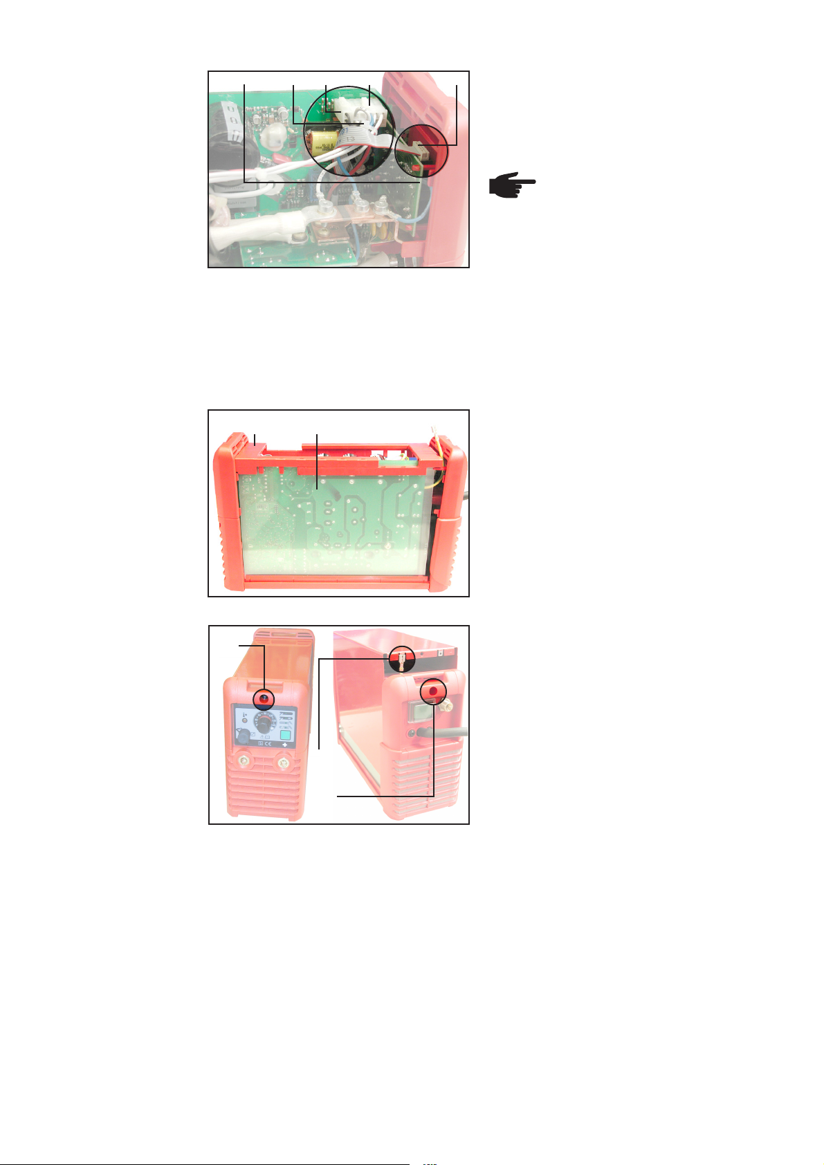
1. Flachbandkabel (42) vom Print FPA15
(5) abstecken
2. Kabelbinder (33) durchtrennen
3. 10-poligen Molexstecker (41) am Print
LCA15 abstecken
4. Verbindung Shunt (54) / Kupferbügel
(55) durch Lösen der Schraube M5x12TX20 (56) trennen
Abb.4
(57) (41) (58)
Abb.5
(56) (55)(54)
5. Messleitung Schweißspannung (rot)
(57) vom 10-poligen Molexstecker (41)
1X10/Pin3 entfernen
- Mittels Molexausziehwerkzeug (58)
(empfohlen: 42,0410,0290)
2
Page 3

Print LCG15
ausbauen
(Fortsetzung)
Abb.6
(52)
(3)
6. „Trafoleitung Mittelanzapfung“ (59)
vorsichtig zur Seite biegen
7. 4 Schrauben M4x20-TX20 (52) vom
Print LCG 15 (3) abschrauben
(59)
8. Print LCG15 (3) vorsichtig abnehmen
Sekundärdiode
ausbauen
(3)
Abb.7
1. 2 Schrauben M4x14-TX20 (31) an der
Diodenhalterung (50) lösen
2. Sekundärdiode mit Diodenhalterung
(50) abnehmen
(50)(31) (31)
Abb.8
3
Page 4

Sekundärdiode
einbauen
Abb.9
1. Kühlkörper mit Kontaktspray und nicht
faserndem Tuch vorreinigen
2. Am Kühlkörper Verunreinigungen bzw.
Unebenheiten mit feinem Schleifpapier
(Körnung P 500 oder feiner) beseitigen
3. Kühlkörper mit Kontaktspray und nicht
faserndem Tuch reinigen
Hinweis! An der Sekundärdiode
ist bereits eine Wärmeleitfolie
aufgeklebt.
- Keine Wärmeleitpaste zusätz-
(60)
lich auftragen
- Die Wärmeleitfolie an der
Unterseite der Sekundärdiode
keinesfalls abziehen
Hinweis! Bei der Montage der Sekundärdiode darauf achten, dass die Uförmige Ausnehmung (60) in Richtung Trafo zeigt.
Auf Sauberkeit achten! Verunreinigungen zwischen Sekundärdiode und Kühlkörper beeinträchtigen die Wärmeübertragung.
4. Diodenhalterung (50) über die Sekundärdiode stülpen
5. 4 Distanzstücke (61) in die Diodenhalterung einsetzen
6. Sekundärdiode mit Diodenhalterung
und eingesetzten Distanzstücken (61)
auf Kühlkörper legen
Abb.10
Abb.11
(31)
(61)(50)
7. Schrauben M4x14-TX20 (31) leicht
andrehen
Hinweis! Vor dem Festziehen der
Schrauben M4x14-TX20 (31)
muss die Sekundärdiode lückenlos und eben auf dem Kühlkörper
aufliegen.
8. Schrauben M4x14-TX20 (31) mit 0,5 Nm
vorziehen
9. Schrauben M4x14-TX20 (31) mit 2,1 Nm
(31)
festziehen
4
Page 5

Print LCG 15
einbauen
(63)
(52) (52)
1. Print LCG15 (3) positionsrichtig auf die
Distanzstücke an der Diodenhalterung
aufsetzen
Hinweis! Vor dem Ansetzen der
4 Innensechskantschrauben
M4x22 - Schlüsselweite 3 - (52),
die Tellerfedern (53) - Abb.13 auf die Schrauben (52) aufschieben.
Abb.12
Abb.13
(57) (41)
(63)
(52) (52)
(52)
(53)
Darauf achten, dass die „Trafoleitungen
Sekundärdiode“ (63) zwischen den Kabelschuhen einen möglichst großen Abstand
zueinander einnehmen.
Hinweis! Eine Überschreitung
des Drehmoments von 1,5 Nm,
für die Schrauben (52), kann zur
Zerstörung der Sekundärdiode
führen.
2. Innensechskantschrauben M4x22 Schlüsselweite 3 - (52) mit 1,5 Nm
festziehen
(54)
(64)
(56)
(55)
(64)
Abb.14
3. Am Kupferbügel (55) den Shunt (54) und die beiden Leitungen „Socket X3” (blau) (64)
befestigen
- Schraube M5x12-TX20 (56) mit 2 Nm festschrauben
4. Messleitung Schweißspannung (rot) (57) in den 10-poligen Molexstecker (41) 1X10/
Pin3 einsetzen
5
Page 6

Print LCG 15
einbauen
(Fortsetzung)
Abb.15
(5)
(33) (41) (42)
(40)
5. 10-poligen Molexstecker (41) am Print
LCA15/1X10 anstecken
6. Kabelbaum für Molexstecker (40) und
(41) mittels Kabelbinder (33) fixieren
Hinweis! Das Flachbandkabel
(42), vor dem Anstecken, über
den Kabelbaum für Molexstecker
(40) und (41) führen.
7. Flachbandkabel (42) gemäß Abb.15
oberhalb des Kabelbaumes verlegen
8. Flachbandkabel (42) am Print FPA15
(5) anstecken
Gehäuse schließen
Abb.16
(34)
(21) (37)
(36)
(35)
1. Printisolation (37) einsetzen
2. Gehäuseversteifung (21) einsetzen
3. „Erdleiter Gehäuse“ (36) positionsrichtig
am Gehäusemantel anstecken
4. Gehäusemantel aufsetzen
5. Schraube 5x25-TX20 (35) an der
Gehäuserückseite festschrauben
6. Schraube 5x25-TX20 (34) an der
Gehäusevorderseite festschrauben
7. Tragegurt montieren
Abb.17
6
Page 7

Installation instructions: LCG15 board and
Warning! Work that is not carried out correctly can cause serious damage and
injury. The actions described below may ONLY be carried out by skilled, trained
technicians! Observe and follow the “Safety rules” in the “Operating
Instructions” manual for the power source.
secondary diode
Safety
Scope of supply
Tools needed
The assembly “LCG 15 board”comprises the following component:
Item Designation N° of items
(3) LCG15 board ..................................................................................................... 1
The assembly “Secondary diode” comprises the following components:
Item Designation N° of items
(4) Secondary diode ................................................................................................ 1
(31) Screws M4x14-TX20.......................................................................................... 2
(50) Diode holder....................................................................................................... 1
(51) Spacers .............................................................................................................. 4
(52) Hexagon-socket screw M4x22 ........................................................................... 4
(53) Cup springs ........................................................................................................ 4
Designation
- Manual torque screwdriver,1 to 6 Nm
- Bit insert TX 20, for torque screwdriver
- Bit insert hexagon-socket, width-across 3, for torque screwdriver
- Molex extractor tool
- Grinding paper (grain P 500 or finer)
- Contact spray
Opening the
housing
(34)
(36)
(35)
Fig.1
7
1. Take off the carrying strap
2. Undo the 5x25-TX20 screw (34) on the
front of the housing
3. Undo the 5x25-TX20 screw (35) on the
rear of the housing
4. Carefully lift the housing box and
disconnect the “housing earth
conductor” (36)
Page 8

Opening the
housing
(continued)
Fig.2
(21) (37)
5. Remove the housing stiffening element
(21)
6. Remove the board insulator (37)
Removing the
LCG15 board
Fig.3
(5)
(33) (41) (42)
1. Disconnect the ribbon cable (42) from
the FPA15 board (5)
2. Cut through the cable binder (33)
3. Disconnect the 10-pole Molex plug
(41) from the LCA15 board
4. Interrupt the connection between the
shunt (54) and the copper bracket (55),
by undoing the M5x12-TX20 screw (56)
Fig.4
(57) (41) (58)
Fig.5
(56) (55)(54)
5. Detach the welding-voltage measuring
lead (red) (57) from the 10-pole Molex
plug (41), 1X10/Pin3
- preferably using the Molex extractor
tool (58) (art. n° 42,0410,0290)
8
Page 9

Removing the
LCG15 board
(continued)
Fig.6
(52)
(3)
6. Carefully bend the “centre-tap
transformer lead“ (59) to one side
7. Unscrew the 4 M4x20-TX20 screws
(52) from the LCG 15 board (3)
(59)
8. Carefully detach the LCG15 board (3)
Removing the
secondary diode
(3)
Fig.7
1. Undo the 2 M4x14-TX20 screws (31) on
the diode holder (50)
2. Detach the secondary diode, together
with the diode holder (50)
(50)(31) (31)
Fig.8
9
Page 10

Fitting the
secondary diode
Fig.9
1. Pre-clean the heat sink with contact
spray and a non-linting cloth
2. Remove any contamination or
unevenness from the heat sink with fine
abrasive paper (grain P 500 or finer)
3. Clean the heat sink with contact spray
and a non-linting cloth
N.B.! There already is a heattransfer film affixed to the
secondary diode.
- Do not apply any heat-transfer
(60)
compound in addition to this
film
- Do NOT peel off the heattransfer film from the underside
of the secondary diode
N.B.! When mounting the secondary diode, make sure that the U-shaped
recess (60) is pointing towards the transformer.
All parts must be kept clean! Any contamination between the secondary diode
and the heat sink will impair the heat-transfer.
4. Put the diode holder (50) over the
secondary diode
5. Insert 4 spacers (61) into the diode
holder
6. Place the secondary diode, complete
with the diode holder and the inserted
spacers (61), onto the heat sink
Fig.10
Fig.11
(31)
(61)(50)
7. Slightly tighten the M4x14-TX20 screws
(31)
N.B.! Before you tighten the
M4x14-TX20 screws (31), the
secondary diode must be lying
completely flat on the heat sink,
without any gaps.
8. Pre-tighten the M4x14-TX20 screws (31)
with a torque of 0.5 Nm
9. Tighten the M4x14-TX20 screws (31)
(31)
with a torque of 2.1 Nm
10
Page 11

Fitting the LCG15
board
Fig.12
(63)
(63)
(52) (52)
(52) (52)
(52)
1. Place the LCG15 board (3) onto the
spacers on the diode holder, in the
correct position
N.B.! Before inserting the 4
hexagon-socket screws M4x22 width-across 3 - (52) into their
holes, push the cup springs (53) Fig.13 - onto the screws (52).
Make sure that the “Secondary diode
transformer leads“ (63) between the cable
lugs are as far as possible apart.
N.B.! When tightening the screws
(52), do not exceed a torque of
1.5 Nm. If you turn the screws
any tighter than this, you risk
destroying the secondary diode.
Fig.13
(57) (41)
(53)
2. Tighten the hexagon-socket screws
M4x22 - width-across 3 - (52) with a
torque of 1.5 Nm
(54)
(64)
(56)
(55)
(64)
Fig.14
3. Fasten the shunt (54) and the two leads “Socket X3” (blue) (64) to the copper bracket
(55)
- tighten the M5x12-TX20 screw (56) with a torque of 2 Nm
4. Insert the welding-voltage measuring lead (red) (57) into the 10-pole Molex plug (41)
1X10/Pin3
11
Page 12

Fitting the LCG15
board
(continued)
Fig.15
(5)
(33) (41) (42)
(40)
5. Plug the 10-pole Molex plug (41) onto
board LCA15/1X10
6. Fix the cable harness for Molex plugs
(40) and (41), using a cable binder (33)
N.B.! Before plugging in the
ribbon cable (42), pass it across
the cable harness for Molex plugs
(40) and (41).
7. Arrange the ribbon cable (42) above the
cable harness, as shown in Fig.15
8. Plug the ribbon cable (42) to board
FPA15 (5)
Closing the
housing
Fig.16
(34)
(21) (37)
(36)
(35)
1. Insert the board insulator (37)
2. Insert the housing stiffening element
(21)
3. Plug the “housing earth conductor” (36)
onto the housing box, in the correct
position
4. Replace the housing box
5. Screw the 5x25-TX20 screw (35) back
onto the rear of the housing
6. Screw the 5x25-TX20 screw (34) back
onto the front of the housing
7. Fit the carrying strap back on again
Fig.17
12
Page 13

Instructions de montage de la carte LCG15 et de la
Attention ! Des travaux mal effectués peuvent occasionner de graves dom-
mages matériels et corporels. Les opérations décrites ci-après doivent être
réalisées uniquement par le personnel qualifié. Respectez les consignes de
sécurité du manuel d’utilisation du source de courant.
diode secondaire
Sécurité
Livraison
Outils
nécessaires
Le sous-groupe „Carte LCG 15“ comprend l’élément suivant :
Pos. Désignation Qté
(3) Carte LCG15 ...................................................................................................... 1
Le sous-groupe „diode secondaire“ comprend les éléments suivants :
Pos. Désignation Qté
(4) Diode secondaire ............................................................................................... 1
(31) Vis M4x14-TX20 ................................................................................................ 2
(50) Porte-diode ........................................................................................................ 1
(51) Écarteurs............................................................................................................ 4
(52) Vis à six pans creux M4x22 ............................................................................... 4
(53) Rondelles Belleville ............................................................................................ 4
Désignation
- Tournevis dynamométrique manuel 1 à 6 Nm
- Embout TX 20, adapté au tournevis dynamométrique
- Embout six pans creux, ouverture de clé de 3, adapté au tournevis dynamométrique
- Outil d’extraction Molex
- Papier abrasif (grain P 500 ou plus fin)
- Spray de contact
Ouvrir le boîtier 1. Enlever la courroie
(34)
(36)
(35)
Fig. 1
13
2. Dévisser la vis 5x25-TX20 (34) placée
sur l’avant du boîtier
3. Dévisser la vis 5x25-TX20 (35) placée
sur l’arrière du boîtier
4. Soulever l’enveloppe du boîtier avec
précaution et débrancher le „câble de
mise à la terre du boîtier“ (36)
Page 14

Ouvrir le boîtier
(suite)
Fig. 2
(21) (37)
5. Enlever le renforcement du boîtier (21)
6. Enlever la plaque isolante de la carte (37)
Démonter la
carte LCG15
Fig. 3
(5)
(33) (41) (42)
1. Débrancher le câble plat (42) de la carte
FPA15 (5)
2. Couper les attaches-câbles (33)
3. Débrancher le connecteur Molex 10
broches (41) de la carte LCA15
4. Couper la jonction shunt (54) / étier en
cuivre (55) en dévissant la vis M5x12TX20 (56)
Fig. 4
(57) (41) (58)
Fig. 5
(56) (55)(54)
5. Retirer la conduite de mesure de la
tension de soudage (rouge) (57) du
connecteur Molex 10 broches (41)
1X10/Pin3
- Avec l’outil d’extraction Molex (58)
(recommandé : 42,0410,0290)
14
Page 15

Démonter la
carte LCG15
(suite)
Fig. 6
(52)
(3)
6. Plier avec précaution la „ligne transformateur de la prise médiane“ (59) sur le
côté
7. Dévisser 4 vis M4x20-TX20 (52) de la
carte LCG 15 (3)
(59)
8. Sortir avec précaution la carte
LCG15 (3)
Démonter la
diode secondaire
(3)
Fig. 7
1. Dévisser les 2 vis M4x14-TX20 (31) du
porte-diode (50)
2. Retirer la diode secondaire avec portediode (50)
(50)(31) (31)
Fig. 8
15
Page 16

Monter la diode
secondaire
Fig. 9
1. Nettoyer préalablement le radiateur
avec un spray de contact et un chiffon
qui ne pluche pas
2. Enlever les impuretés et les défauts de
planéité du refroidisseur avec un papier
abrasif (grain P 500 ou plus fin)
3. Nettoyer le radiateur avec un spray de
contact et un chiffon qui ne pluche pas
Remarque ! Un film thermoconducteur est déjà collé sur la diode
secondaire.
(60)
- Ne pas enduire de pâte thermoconductrice
- N’enlever en aucun cas le film
thermoconducteur qui se
trouve sur l’arrière de la diode
secondaire
Remarque ! Lorsque vous montez la diode secondaire, faites attention à ce
que la cavité en U (60) soit tournée vers le transformateur.
Veillez à ce que tout reste propre ! Les impuretés entre la diode secondaire et
le refroidisseur restreignent la transmission de la chaleur.
Fig. 10
4. Dégager le porte-diode (50) de la diode
secondaire
5. Placer 4 écarteurs (61) dans le portediode
6. Placer la diode secondaire avec portediode et écarteurs en place (61) sur le
refroidisseur
(61)(50)
7. Visser légèrement les vis M4x14-TX20
(31)
Remarque ! Avant de serrer à
fond les vis M4x14-TX20 (31), la
diode secondaire doit être parfaitement placée à plat sur le
refroidisseur.
Fig. 11
(31)
(31)
8. Pre-serrer à fond les vis M4x14-TX20
(31) à 0,5 Nm
9. Serrer à fond les vis M4x14-TX20 (31) à
2,1 Nm
16
Page 17

Monter la carte
LCG 15
Fig. 12
(63)
(63)
(52) (52)
(52) (52)
(52)
1. Placer la carte LCG15 (3) dans la
bonne position sur les écarteurs du
porte-diode
Remarque ! Avant de placer les
4 vis à six pans creux M4x22 ouverture de clé de 3 - (52),
glissez les rondelles Belleville
(53) - fig. 13 - sur les vis (52).
Veillez à ce que les „lignes transformateur
de la diode secondaire“ (63) soient éloignées le plus possibles l’une de l’autre
entre les cosses.
Remarque ! Si vous dépassez le
couple de serrage de 1,5 Nm
pour les vis (52), vous pouvez
abîmer la diode secondaire.
Fig. 13
(57) (41)
(53)
2. Serrer les vis à six pans creux M4x22 ouverture de clé de 3 - (52) avec 1,5
Nm
(54)
(64)
(56)
(55)
(64)
Fig. 14
3. Fixer le shunt (54) et les deux lignes „Socket X3“ (bleues) (64) sur l’étrier en cuivre
(55)
- Visser la vis M5x12-TX20 (56) avec 2 Nm
4. Placer la conduite de mesure de la tension de soudage (rouge) (57) dans le connecteur Molex 10 broches (41) 1X10/Pin3
17
Page 18
Monter la carte
LCG 15
(suite)
(5)
(33) (41) (42)
(40)
5. Brancher le connecteur Molex 10
broches (41) sur la carte LCA15/1X10
6. Fixer le faisceau de câbles des connecteurs Molex (40) et (41) avec des
attaches-câbles (33)
Remarque ! Avant de brancher le
câble plat (42), faites le passer
au-dessus du faisceau de câbles
des connecteurs Molex (40) et
(41).
Fermer le boîtier
Fig. 15
Fig. 16
(34)
(21) (37)
(36)
7. Poser le câble plat (42) au-dessus du
faisceau de câbles conformément à la
fig. 15
8. Brancher le câble plat (42) sur la carte
FPA15 (5)
1. Placer la plaque isolante de la carte
(37)
2. Poser le renforcement du boîtier (21)
3. Brancher le „câble de mise à la terre du
boîtier“ (36) dans la bonne position sur
l’enveloppe du boîtier
4. Monter l’enveloppe
5. Visser la vis 5x25-TX20 (35) sur
l’arrière du boîtier
6. Visser la vis 5x25-TX20 (34) sur l’avant
du boîtier
7. Monter la courroie
Fig. 17
(35)
18
 Loading...