

Page 1
Fronius prints on elemental chlorine free paper (ECF) sourced from certified sustainable forests (FSC).
/ Perfect Charging / Perfect Welding / Solar Energy
LCA 35
Installationsanleitung
DE
Diverses
Installation instructions
EN
Miscellaneous
Instructions d'installation
FR
Divers
42,0410,1394 005-20052021
Page 2

Page 3

Inhaltsverzeichnis
Allgemeines 4
Sicherheit 4
Lieferumfang 4
Erforderliches Werzeug 4
Print LCA 35 ausbauen 5
Gehäuse öffnen 5
Steck- und Kabelverbindungen trennen 5
Print vom Kühlkörper lösen / Print herausnehmen 7
Print LCA 35 einbauen 8
Vorbereitung 8
Print LCA 35 am Kühlkörper befestigen 8
Steck- und Kabelverbindungen herstellen 9
Steuerprint STTP 1 / 2 auf Schäden überprüfen 10
Gehäuse schließen / Sicherheitstechnische Überprüfung durchführen 12
Gehäuse schließen 12
Sicherheitstechnische Überprüfung durchführen 12
DE
3
Page 4

Allgemeines
Sicherheit
WARNUNG!
Gefahr durch fehlerhaft durchgeführte Arbeiten
Schwerwiegende Personen- und Sachschäden können die Folge sein.
Nachfolgend beschriebene Tätigkeiten dürfen nur von geschultem Fachpersonal
▶
durchgeführt werden! Beachten Sie die Sicherheitsvorschriften in der Bedienungsanleitung der Stromquelle.
WARNUNG!
Gefahr durch einen elektrischen Schlag
Schwerwiegende Personenschäden können die Folge sein.
Netzschalter der Stromquelle in Stellung - O - schalten
▶
Stromquelle vom Netz trennen
▶
Deutlich lesbares und verständliches Warnschild gegen Wiedereinschalten anbrin-
▶
gen
Nach dem Öffnen des Gerätes gegebenenfalls spannungsführende Bauteile (z.B.
▶
Kondensatoren) entladen.
VORSICHT!
Gefahr durch elektrische Entladung.
Beschädigung elektronischer Bauteile kann die Folge sein.
Bei Austausch und Installation von Komponenten geeignete ESD Schutzmaßnah-
▶
men treffen.
Lieferumfang Im Lieferumfang ist enthalten:
- Print LCA 35 zusatzgeprüft
- 20 Stück Linsenschrauben 4 x 10 mm
- Wärmeleitpaste 10 ml
- Auftragwerkzeug (Lackierwalze) für Wärmeleitpaste
Erforderliches
Werzeug
Für den Austausch des Prints LCA 35 ist zusätzlich zu dem im Lieferumfang enthaltenen
Werkzeug folgendes Werkzeug erforderlich:
- Schraubendreher TX20 und TX25 mit einstellbarem Drehmoment
- Ringschlüssel SW 17 mm)
4
Page 5
Print LCA 35 ausbauen
(4)(3)
(2)
(1)
Gehäuse öffnen Für ein einfaches Hantieren im Gerät Seitenteile, Gehäuse-Oberteil und Griffrohr entfer-
nen:
Schrauben an den Seitenteilen herausdrehen und Seitenteile entfernen
1
An der rechten Gerätseite Abdeckfolie herausnehmen
2
Zwischenkreis-Kondensatoren entladen (z.B. Klemmen -X10 und -X13 über einen
3
Entladewiderstand verbinden)
Schrauben an der Vorder- und Rückseite des Gehäuse-Oberteils herausdrehen und
4
Griffrohr sowie Gehäuse-Oberteil entfernen.
Zusätzlich bei TIG-Gerät:
Mutter am Gas-Magnetventil an der Geräte-Rückseite mittels Ringschlüssel lösen
5
und entfernen
Gas-Magnetventil nach hinten in das Gerät zurückziehen
6
WICHTIG! Entfernte Gehäuseteile und Schrauben während der Arbeiten an einem
sicheren und sauberen Ort aufbewahren.
DE
Steck- und Kabelverbindungen
trennen
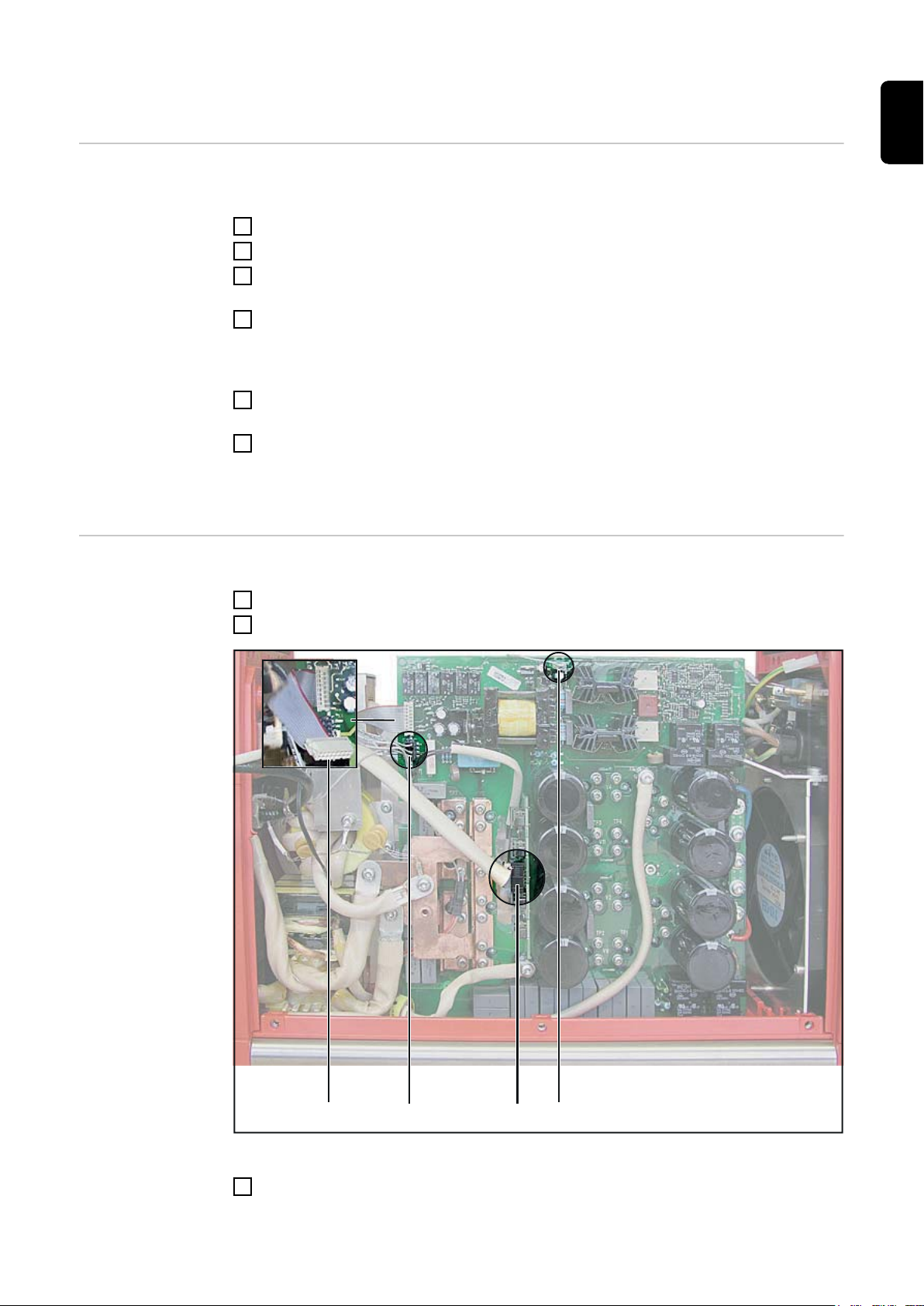
Zum Demontieren des Prints LCA 35 folgende Reihenfolge einhalten:
Steckverbindung (1) am Steuerungsprint STTP 1 / 2 trennen
1
Steckverbindungen (2) - (4) am Print LCA 35 trennen
2
Steckverbindungen trennen
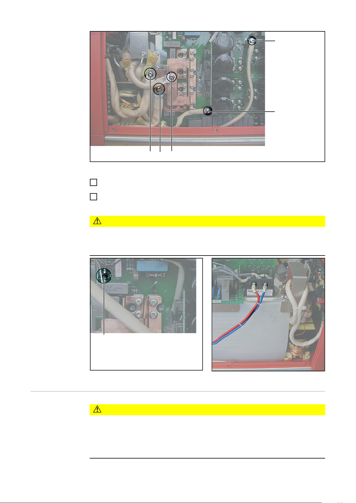
Kabelverbindungen trennen: 5 Schrauben (5) - (9), primär- und sekundärseitig her-
3
ausdrehen
5
Page 6
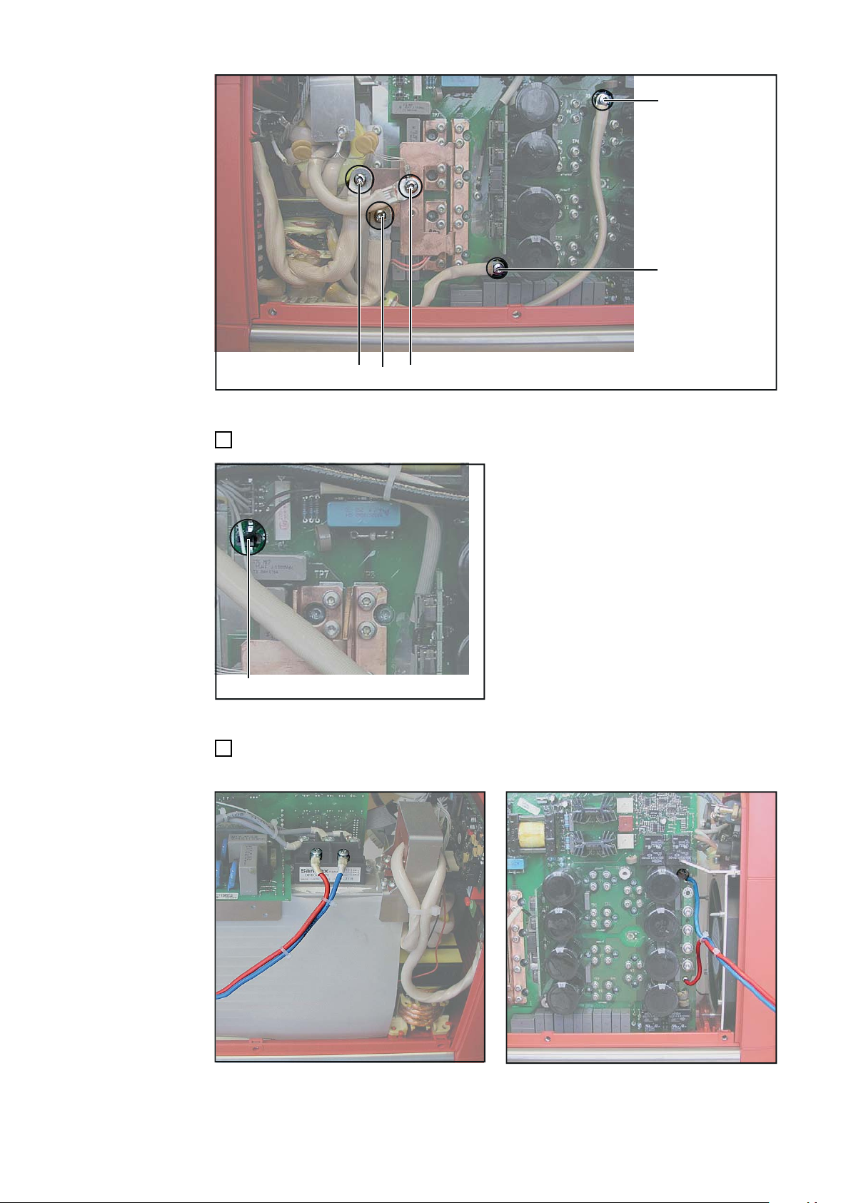
(5)
(6)
(7)
(8)
(9)
Kabelverbindungen trennen
(10)
Thermofühler (10) abstecken
4
Thermofühler abstecken
An der linken Geräteseite DC-Leitung vom Gleichrichter abschrauben und durch das
5
Gehäuse auf die andere Geräteseite ausfädeln.
DC-Leitungen vom Gleichrichter trennen
DC-Leitungen ausfädeln
6
Page 7
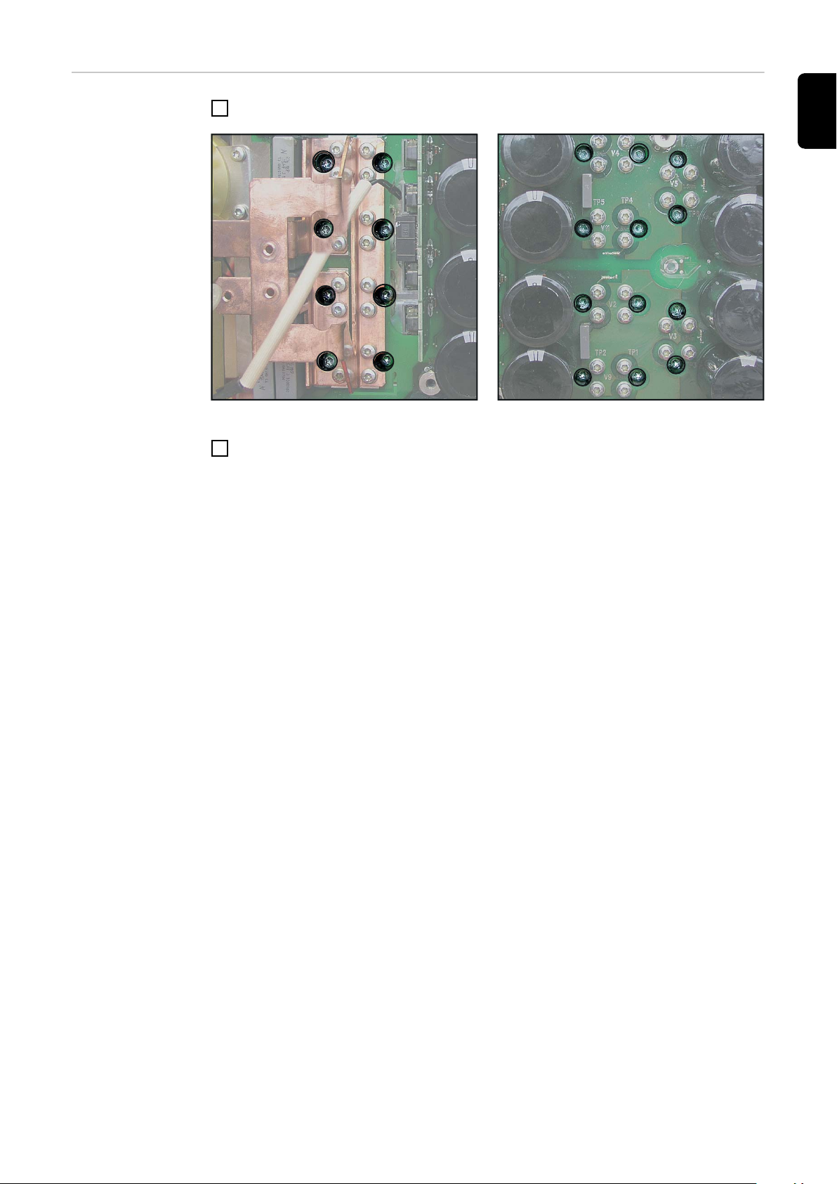
Print vom
Kühlkörper
lösen / Print herausnehmen
20 Schrauben zur Printbefestigung gemäß Abbildungen herausdrehen
1
Linke Seite, Print vom Kühlkörper lösen Rechte Seite, Print vom Kühlkörper lösen
Print LCA 35 vorsichtig nach oben aus dem Gehäuse herausnehmen
2
DE
7
Page 8

Print LCA 35 einbauen
Vorbereitung WICHTIG! Vor dem Einsetzen des Prints LCA 35, Kühlkörper vollständig von Resten der
alten Wärmeleitpaste reinigen.
Vor Auftragen der Wärmeleitpaste auf den Print LCA 35, Wärmeleitpaste mittels im
1
Lieferumfang enthaltenen Auftragwerkzeug auf einer sauberen, ebenen und glatten
Oberfläche gleichmäßig verteilen.
Wärmeleitpaste dünn und gleichmäßig an den Leistungsmodulen des Print LCA 35
2
auftragen
Print LCA 35 am
Kühlkörper
befestigen
Wärmeleitpaste gleichmäßig verteilen
Wärmeleitpaste gleichmäßig auf die Leistungsmodule
auftragen
Nach dem gleichmäßigen Auftragen von Wärmeleitpaste auf die Leistungsmodule, Print
LCA 35 wie folgt am Kühlkörper befestigen:
Print LCA 35 vorsichtig auf den gereinigten Kühlkörper aufsetzen
1
Mittels nachfolgend beschriebener Reihenfolge Print mit angegebenem Drehmoment
2
am Kühlkörper befestigen
WICHTIG! Gefahr von Beschädigung der Leistungsmodule oder ungenügender Wärmeabfuhr auf Grund unsachgemäßem Anziehen der Befestigungsschrauben. Für das Montieren nur die im Lieferumfang enthaltenen Linsenschrauben 4 x 10 mm verwenden. Den
nachfolgend beschriebenen Ablauf mit angegebenem Drehmoment unbedingt einhalten.
8
Page 9

12
11
10
17
18
8
20
19
9
5
6
7
2
3
5
1
1
2
3
4
4
13
14
15
16
Print LCA 35 am Kühlkörper befestigen
(4)(3)
(2)
(1)
DE
Steck- und Kabelverbindungen
herstellen
Steckverbindungen (1) am Steuerungsprint STTP 1 / 2 herstellen
1
Steckverbindungen (2) - (4) am Print LCA 35 herstellen
2
Steckverbindungen herstellen
Kabel mittels 5 Schrauben (5) - (9), primär- und sekundärseitig am Print befestigen.
3
Anzugs-Drehmoment: 2,7 Nm
WICHTIG! An Position (7) Stromsensor- und Kondensator-Kabel befestigen.
9
Page 10
(5)
(6)
(7)
(8)
(9)
Kabelverbindungen herstellen
(10)
Thermofühler anstecken
4
DC-Leitung durch das Gehäuse zur linken Geräteseite einfädeln und DC-Leitung
5
polrichtig mit dem Gleichrichter verbinden.
VORSICHT!
Gefahr durch vertauschtes Anschließen der DC-Leitungen.
Schwere Sachschäden können die Folge sein
Der rote Draht ist „+“, der blaue Draht ist „-“.
▶
Steuerprint STTP
1 / 2 auf Schäden
überprüfen
10
Thermofühler anstecken
VORSICHT!
Gefahr durch einen defekten Steuerprint STTP 1 / 2.
Schwere Sachschäden können die Folge sein
Bei jedem Austausch des Leistungsteil-Prints LCA 35 müssen die 4 Treiber-ICs am
▶
Steuerprint STTP 1 / 2 auf Beschädigungen überprüft werden.
Ein defekter Steuerprint STTP 1 / 2 muss ebenfalls sofort getauscht werden.
▶
DC-Leitung einfädeln und anschließen
Page 11
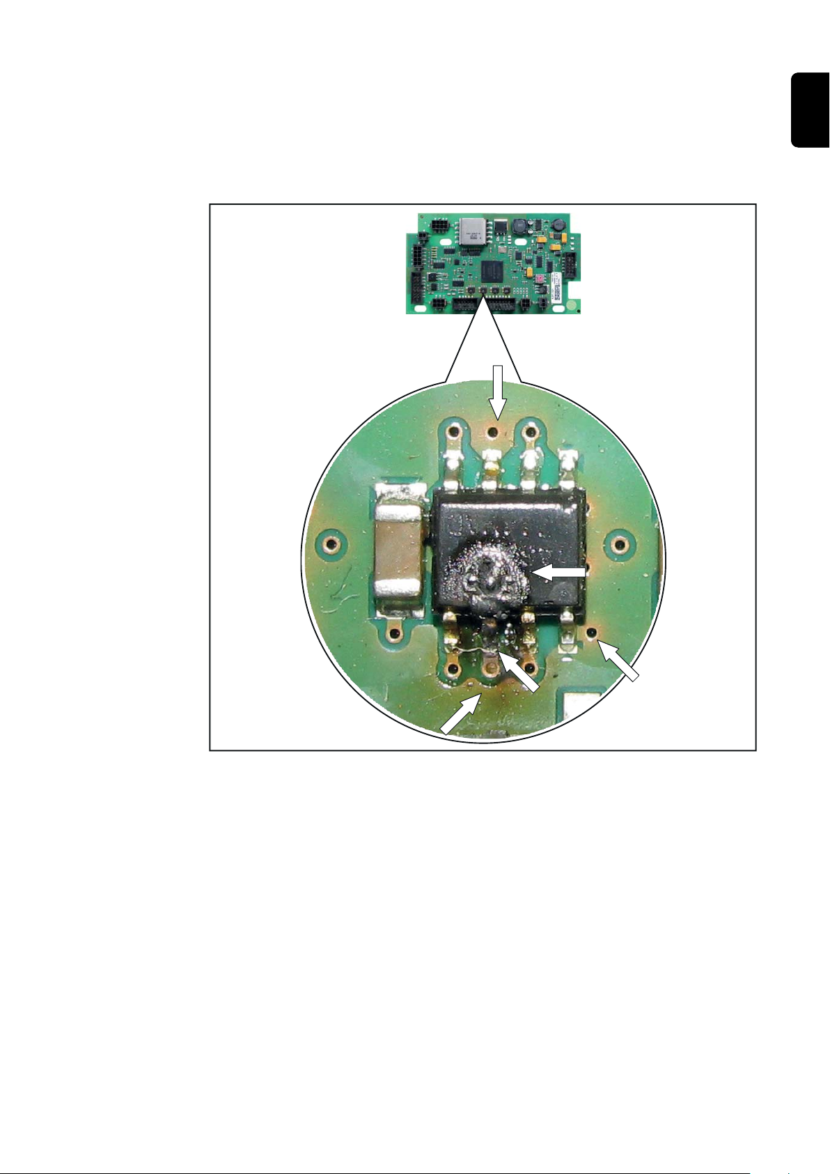
Erkennungsmerkmale von beschädigten Treiber-ICs am Steuerprints STTP 1 / 2:
a)
a)
a)
b)
c)
a) Braunfärbung des Isolierlackes rund um die Lötstellen der Treiber-IC
b) Beschädigung der Treiber-IC Gehäuse (z.B. Loch im Gehäuse)
c) Angeschmorte Lötstellen
WICHTIG! Weist der Steuerprint STTP 1 / 2 auch nur eines der oben angeführten Erkennungsmerkmale für eine Beschädigung auf, muss der Print gewechselt werden.
DE
Defekte Treiber-ICs am Steuerprint STTP 1 / 2
11
Page 12

Gehäuse schließen / Sicherheitstechnische
Überprüfung durchführen
Gehäuse
schließen
WARNUNG!
Gefahr durch elektrischen Strom wegen unzureichende Schutzleiter-Verbindungen.
Schwerwiegende Personen- und Sachschäden können die Folge sein.
Die Gehäuseschrauben stellen eine geeignete Schutzleiter-Verbindung für die
▶
Erdung des Gehäuses dar und dürfen keinesfalls durch andere Schrauben ohne
zuverlässige Schutzleiter-Verbindung ersetzt werden.
Nur bei TIG-Gerät: Gas-Magnetventil einbauen und befestigen
1
Griffrohr in das Gehäuse einsetzen
2
Schutzleiter-Stecker am Gehäusedeckel anstecken, Gehäusedeckel einsetzen und
3
befestigen.
Abdeckfolie an der rechten Geräteseite einsetzen
4
Sicherheitstechnische
Überprüfung
durchführen
Abdeckfolie an der rechten Geräteseite
Seitenteile einsetzen und befestigen.
5
WICHTIG! Vor Inbetriebnahme des Gerätes, Sicherheitstechnische Überprüfung
durchführen.
Gemäß den nationalen und regionalen Bestimmungen ist nach folgenden Maßnahmen
eine Sicherheitstechnische Überprüfung durchzuführen:
- nach Veränderung
- nach Ein- oder Umbauten
- nach Reparatur, Pflege und Wartung
- mindestens alle zwölf Monate
Die neueste Version der Arbeitsanweisung „Sicherheitstechnische Überprüfung von
Schweißsystemen im Zuge von Reparatur und Wartung“ finden sie im Internet auf unserer Hompage.
12
Page 13

Contents
General 14
Safety 14
Scope of supply 14
Tools required 14
Removing board LCA 35 15
Opening the housing 15
Disconnecting plugs and cables 15
Unscrewing board from cooling element/removing board 17
Installing board LCA 35 18
Preparations 18
Fastening board LCA 35 to cooling element 18
Connecting plugs and cables 19
Checking the STTP 1/2 control board for damage 20
Closing housing/safety inspection 22
Closing the housing 22
Safety inspection 22
EN
13
Page 14

General
Safety
WARNING!
Danger due to incorrectly performed work.
This can result in serious injury and damage to property.
The following activities must only be carried out by trained and qualified personnel!
▶
Take note of the safety rules in the power source operating instructions.
WARNING!
Danger of an electric shock.
This can result in serious injury and damage to property. Before opening the device:
Turn the power source mains switch to the "O" position
▶
Disconnect the power source from the mains
▶
Attach a clearly legible and easy-to-understand warning sign to prevent anyone swit-
▶
ching it on again
After opening the device, discharge any live components (e.g. capacitors).
▶
CAUTION!
Risk of electrical discharge.
Damage to electrical components can result
Suitable measures should be taken to protect against ESD when replacing and
▶
installing components
Scope of supply The scope of supply contains:
- board LCA 35
- 20 x cheese head screws 4 x 10 mm
- heat conductive paste 10 ml
- application tool (varnishing roller) for heat conductive paste
Tools required In addition to the tool contained in the scope of supply, you will also need the following
tool for replacing the LCA 35 board:
- TX20 and TX25 screwdrivers with adjustable torque
- Ring spanner (17 mm)
14
Page 15

Removing board LCA 35
(4)(3)
(2)
(1)
Opening the
housing
Disconnecting
plugs and cables
Remove side panels, upper part of housing and handle for easier handling:
Unscrew screws from the side panels and remove panels
1
Remove protective sheet from the right-hand side of the machine
2
Discharge intermediate circuit capacitors (e.g. connect -X10 and -X13 terminals
3
using a discharge resistor)
Unscrew screws from the front and rear of the upper part of the housing and remove
4
the upper part.
On TIG machine, carrying out the following as well:
Use a ring spanner to loosen and remove nut from gas solenoid valve on the rear of
1
the machine
Pull gas solenoid valve back into the machine
2
IMPORTANT! While performing work on the machine, keep removed housing sections
and screws in a safe, clean place.
To remove the LCA 35 board, observe the following order:
Disconnect plug (1) from control board STTP1 / 2
1
Disconnect plugs (2) - (4) from board LCA 35
2
EN
Disconnecting plugs
Connect cables: Unscrew 5 screws (5) - (9) from primary and secondary voltage
3
connections
15
Page 16

(5)
(6)
(7)
(8)
(9)
Disconnecting cables
(10)
Unplug temperature sensor (10)
4
Unplugging temperature sensor
On the left side of the machine, unscrew DC cable from the rectifier and feed it out
5
through the housing, on the other side of the machine.
16
Disconnecting DC cables from the rectifier
Feeding out DC cables
Page 17

Unscrewing
board from cooling element/
removing board
Unscrew 20 screws used to hold PC board in place, as shown in illustrations
1
EN
Left-hand side, unscrewing PC board from cooling
element
Carefully lift PC board LCA 35 and remove from the housing
2
Right-hand side, unscrewing PC board from cooling
element
17
Page 18

Installing board LCA 35
Preparations IMPORTANT! Before inserting the LCA 35 board, completely clean cooling element of
residue from previous heat conductive paste.
Before applying heat conductive paste to the LCA 35 board, evenly distribute paste
1
on a clean, level and smooth surface using the application tool contained in the
scope of supply
Apply a thin, even coating of heat conductive paste to the power modules on the
2
LCA 35 board
Fastening board
LCA 35 to cooling
element
Evenly distributing heat conductive paste
Evenly applying heat conductive paste to the power
modules
After evenly applying heat conductive paste to the power modules, fasten LCA 35 board
to the cooling element as follows:
Carefully place LCA 35 board on the clean cooling element
1
Using the sequence described below, fasten board to the cooling element with the
2
given torque
IMPORTANT! Risk of damage to the power modules or insufficient heat dissipation due
to tightening the fastening screws incorrectly. Only use the 4 x 10 mm cheese-head
screws contained in the scope of supply. You MUST keep to the torque given when carrying out the following steps.
18
Page 19

12
11
10
17
18
8
20
19
9
5
6
7
2
3
5
1
1
2
3
4
4
13
14
15
16
Fastening board LCA 35 to cooling element
(4)(3)
(2)
(1)
EN
Connecting plugs
and cables
Connect plug (1) to control board STTP1
1
Connect plugs (2) - (4) to board LCA 35
2
Inserting plugs into sockets
Using 5 screws (5) - (9), fasten cable to primary and secondary voltage connections
3
on PC board. Tightening torque: 2.7 Nm
IMPORTANT! Fasten current sensor and capacitor cable to position (7).
19
Page 20

(5)
(6)
(7)
(8)
(9)
Connecting cables
(10)
Plug in temperature sensor
4
Feed DC cable in through the housing on the left side of the machine, and connect
5
cable to the correct poles on the rectifier.
CAUTION!
Danger of incorrectly connecting DC cables.
This can cause serious damage to the equipment.
The red wire is „+“, the blue wire is „-“.
▶
Checking the
STTP 1/2 control
board for damage
20
Plugging in temperature sensor
CAUTION!
Danger of faulty STTP 1/2 control board.
This can result in damage to other components.
Whenever the LCA 25 power module board is replaced, the four driver ICs on the
▶
STTP 1/2 control board must be checked for damage.
If the STTP 1/2 is faulty, it must be replaced immediately.
▶
Feeding in and connecting DC cable
Page 21

How to identify damaged driver ICs on the STTP 1/2 control board:
a)
a)
a)
b)
c)
a) The insulating varnish around the driver IC solder points is brown
b) The driver IC housing is damaged, e.g. holes in housing
c) Scorched solder points
IMPORTANT! If the STTP 1/2 control board exhibits one or more of the above characteristics, the entire board must be replaced.
EN
Faulty driver ICs on STTP 1/2 control board
21
Page 22

Closing housing/safety inspection
Closing the
housing
WARNING!
Danger from electrical current due to inadequate ground conductor connection.
This can result in serious injury and damage to property.
The housing screws provide a suitable PE conductor connection for grounding (eart-
▶
hing) the housing and must NOT be replaced by any other screws which do not provide a reliable PE conductor connection.
Only on TIG machine: insert gas solenoid valve and fasten in place.
1
Insert the handle into the housing
2
Insert PE conductor plug into housing cover, put housing cover in place and fasten in
3
place.
Insert protective sheet on the right-hand side of the machine
4
Protective sheet on the right-hand side of the machine
Insert side panels and fasten in place.
5
IMPORTANT! Before commissioning the machine, carry out safety inspection.
Safety inspection A safety inspection must be carried out according to national and local regulations:
- after any changes are made
- after any additional parts are installed and after any conversions
- after repair, care and maintenance
- at least once every twelve months
The latest version of the „Safety inspection of welding systems as part of repair and
maintenance“ work instructions can be found at our internet homepage.
22
Page 23

Sommaire
Généralités 24
Sécurité 24
Livraison 24
Outils requis 24
Démonter le circuit imprimé LCA 35 25
Ouvrir le boîtier 25
Débrancher les connexions et les liaisons par câble 25
Détacher le circuit imprimé du dissipateur thermique / Sortir le circuit imprimé 27
Monter le circuit imprimé LCA 35 28
Préparation 28
Fixer le circuit imprimé LCA 35 au dissipateur thermique 28
Établir les connexions et les liaisons par câble 29
Vérifier le bon état du circuit imprimé de commande STTP 1 / 2 31
Fermer le boîtier / Réaliser un contrôle technique de sécurité 32
Fermer le boîtier 32
Réaliser un contrôle technique de sécurité 32
FR
23
Page 24

Généralités
Sécurité
AVERTISSEMENT!
Danger en cas d'erreurs en cours d'opération.
Cela peut entraîner des dommages corporels et matériels graves.
Les opérations décrites ci-après doivent être effectuées exclusivement par le per-
▶
sonnel qualifié et formé ! Respectez les consignes de sécurité figurant dans le mode
d’emploi de la source de courant.
AVERTISSEMENT!
Danger en cas de décharge électrique.
Cela peut entraîner des dommages matériels graves.
Commuter l'interrupteur secteur de la source de courant en position - O -
▶
Débrancher la source de courant du secteur.
▶
Placer un écriteau parfaitement lisible et compréhensible sur l’appareil afin que per-
▶
sonne ne le remette en marche
Après ouverture de l'appareil, décharger le cas échéant les éléments conducteurs
▶
de tension (par ex. condensateurs).
ATTENTION!
Risque de décharge électrique.
Cela peut entraîner des dommages aux composants électroniques.
Appliquer les mesures de sécurité contre les décharges électrostatiques appro-
▶
priées lors du remplacement et de l’installation des composants.
Livraison Sont inclus dans la livraison :
- Circuit imprimé LCA 35 testé comme composant auxiliaire
- 20 vis à tête cylindrique bombée 4 x 10 mm
- Pâte thermique 10 ml
- Outil d’application (rouleau à vernir) pour la pâte thermique
Outils requis En plus des outils contenus dans la livraison, les outils supplémentaires suivants sont
nécessaires pour le remplacement du circuit imprimé LCA 35 :
- Tournevis TX20 et TX25 avec couple de serrage réglable
- Clé polygonale SW 17 mm
24
Page 25

Démonter le circuit imprimé LCA 35
(4)(3)
(2)
(1)
Ouvrir le boîtier Pour plus de liberté de mouvement, enlever les panneaux latéraux, le cache supérieur et
la poignée tube du boîtier :
Dévisser les vis des panneaux latéraux et enlever les panneaux latéraux
1
Enlever la plaque d’obturation sur la face droite de l’appareil
2
Décharger les condensateurs du circuit intermédiaire (relier par exemple les bornes -
3
X10 et -X13 au moyen d’une résistance de décharge)
Dévisser les vis à l’avant et à l’arrière du cache supérieur du boîtier et enlever le
4
cache supérieur du boîtier
En outre, sur les appareils TIG :
Desserrer puis retirer l’écrou de l’électrovanne de gaz situé sur la face arrière de
1
l’appareil au moyen d’une clé polygonale
Repousser l’électrovanne de gaz vers l’arrière dans l’appareil
2
IMPORTANT! Conserver les éléments du boîtier et les vis dans un endroit sécurisé et
propre pendant les interventions sur l’appareil
FR
Débrancher les
connexions et les
liaisons par câble
Procéder dans l’ordre indiqué ci-dessous pour démonter le circuit imprimé LCA 35 :
Débrancher la connexion (1) au niveau du circuit de commande STTP1 / 2
1
Débrancher les connexions (2) - (4) au niveau du circuit imprimé LCA 35
2
Débrancher les connexions
Débrancher les liaisons par câble : Dévisser 5 vis (5) - (9) du côté primaire et secon-
3
daire
25
Page 26

(5)
(6)
(7)
(8)
(9)
Débrancher les liaisons par câble
(10)
Débrancher le capteur thermique (10)
4
Débrancher le capteur thermique
Dévisser le câble CC du redresseur sur la face gauche de l’appareil et le dégager de
5
l’autre côté de l’appareil au travers du boîtier.
26
Débrancher les câbles CC du redresseur
Dégager les câbles CC
Page 27

Détacher le circuit imprimé du
dissipateur thermique / Sortir le
circuit imprimé
Retirer les 20 vis de fixation du circuit imprimé conformément aux illustrations
1
FR
Côté gauche, détacher le circuit imprimé du dissipateur thermique
Dégager doucement le circuit imprimé LCA 35 du boîtier par le haut
2
Côté droit, détacher le circuit imprimé du dissipateur
thermique
27
Page 28

Monter le circuit imprimé LCA 35
Préparation IMPORTANT! Avant de mettre en place le circuit imprimé LCA 35, retirer tous les résidus
de l’ancienne pâte thermique sur le dissipateur thermique.
Avant d’appliquer la pâte thermique sur le circuit imprimé LCA 35, étaler uni-
1
formément la pâte thermique à l’aide de l’outil d’application compris dans la livraison
sur une surface propre, plane et lisse.
Appliquer la pâte thermique en couche fine et uniforme sur les modules de puis-
2
sance du circuit imprimé LCA 35
Fixer le circuit
imprimé LCA 35
au dissipateur
thermique
Répartir uniformément la pâte thermique
Répartir uniformément la pâte thermique sur les
modules de puissance
Après application uniforme de la pâte thermique sur les modules de puissance, fixer
comme suit le circuit imprimé LCA 35 au dissipateur thermique :
Placer doucement le circuit imprimé LCA 35 sur le dissipateur thermique nettoyé
1
Fixer le circuit imprimé au dissipateur thermique en respectant l’ordre ci-dessous,
2
ainsi que le couple de serrage indiqué
IMPORTANT! Risque de dommage des modules de puissance ou d’évacuation insuffisante de la chaleur si les vis de fixation ne sont pas serrées comme il convient. Pour le
montage, n’utiliser que les vis à tête cylindrique bombée 4 x 10 mm fournies dans la livraison. Respecter impérativement le déroulement ci-dessous ainsi que le couple de serrage indiqué
28
Page 29

12
11
10
17
18
8
20
19
9
5
6
7
2
3
5
1
1
2
3
4
4
13
14
15
16
Fixer le circuit imprimé LCA 35 au dissipateur thermique
(4)(3)
(2)
(1)
FR
Établir les connexions et les liaisons par câble
Établir les connexions (1) au niveau du circuit de commande STTP1
1
Établir les connexions (2) - (4) au niveau du circuit imprimé LCA 35
2
Établir les connexions
Fixer le câble au circuit imprimé avec 5 vis (5) - (9) du côté primaire et secondaire.
3
Couple de serrage : 2,7 Nm
29
Page 30

IMPORTANT! Fixer le câble du détecteur de courant et du condensateur à la position
(5)
(6)
(7)
(8)
(9)
(10)
(7).
Établir les connexions par câble
Rebrancher le capteur thermique
4
Relier le câble CC à la face gauche de l’appareil au travers du boîtier et raccorder le
5
câble CC au redresseur en respectant la polarité.
ATTENTION!
Risque en cas de raccord non convenable des câbles CC.
Des dommages matériels graves peuvent en résulter.
Le fil rouge correspond au „+“, le bleu au „-“.
▶
30
Brancher le capteur thermique
Insérer et brancher le câble CC
Page 31

Vérifier le bon
a)
a)
a)
b)
c)
état du circuit
imprimé de commande STTP 1 / 2
ATTENTION!
Danger dû á un circuit imprimé de commande STTP 1 / 2 défectueux.
Cela peut entraîner des dommages matériels graves.
Lors de chaque échange du circuit imprimé d’étage de puissance LCA 25, il est
▶
nécessaire de vérifier le bon état des 4 pilotes IC du circuit imprimé de commande
STTP 1 / 2.
Un circuit imprimé de commande STTP 1 / 2 défectueux doit être remplacé
▶
immédiatement.
Comment reconnaître des pilotes IC endommagés sur le circuit imprimé de commande
STTP 1 / 2 :
a) coloration marron du vernis isolant autour des points de brasage des pilotes IC
b) boîtier des pilotes IC endommagé (p. ex. trou dans le boîtier)
c) points de brasage consumés
IMPORTANT! Même si le circuit imprimé de commande STTP 1 / 2 ne présente que
l’une des caractéristiques de dommage précitées, il doit être échangé.
FR
Pilotes IC défectueux sur le circuit imprimé de commande STTP 1 / 2
31
Page 32

Fermer le boîtier / Réaliser un contrôle technique
de sécurité
Fermer le boîtier
AVERTISSEMENT!
Danger en cas de connexions insuffisantes des conducteurs de terre.
Cela peut entraîner des dommages corporels et matériels graves.
Les vis du carter constituent une connexion de terre appropriée pour la mise à la
▶
terre du carter de l’appareil et ne doivent en aucun cas être remplacées par d’autres
vis qui n’offriraient pas ce type de connexion fiable de la terre.
Uniquement pour les appareils TIG : Monter et fixer l’électrovanne de gaz
1
Insérer la ploignée tube dans le boîtier
2
Brancher le connecteur de mise à la terre au capot du boîtier puis mettre en place et
3
fixer le capot du boîtier
Remettre en place la plaque d’obturation sur la face droite de l’appareil
4
Réaliser un
contrôle technique de sécurité
Plaque d’obturation sur la face droite de l’appareil
Remettre en place et fixer les panneaux latéraux
5
IMPORTANT! Avant de mettre l’appareil en service, réaliser un contrôle technique de
sécurité.
Après réalisation de l’une quelconque des opérations ci-dessous, effectuer un contrôle
technique de sécurité conformément aux prescriptions nationales et régionales :
- après toute modification
- après montage ou conversion
- après toute opération de réparation, entretien et maintenance
- au moins tous les douze mois
La dernière version des instructions de travail „Contrôle technique de sécurité des
systèmes de soudage dans le cadre des opérations de réparation et d’entretien“ est disponible sur Internet, sur notre page d’accueil.
32
Page 33

FR
33
Page 34

34
Page 35

FR
35
Page 36

FRONIUS INTERNATIONAL GMBH
Froniusstraße 1
A-4643 Pettenbach
AUSTRIA
contact@fronius.com
www.fronius.com
Under www.fronius.com/contact you will find the addresses
of all Fronius Sales & Service Partners and locations
 Loading...