

Page 1

Installation
Instructions
Schlüsselschalter
Keylock switch
Bouton à clé
Installationsanleitung
DE
Installation Instructions
EN
Instructions d'installation
FR
42,0410,0726 004-17082022
Page 2

Page 3

Einbauanleitung
(6)
Allgemeines Das Einbauset „Schlüsselschalter kurz“ 4,100,283 und „Schlüsselschalter“
4,100,317 und „Schlüsselschalter 3-stufig“ 4,100,524 ist für die Stromquellen
TS 4000 / 5000 sowie TPS 2700 / 3200 / 4000 / 5000 geeignet.
WICHTIG! Einbauset Schlüsselschalter 4,100,317: Vor Einsetzen des
Schlüsselschalters, den mitgelieferten
Distanzring (6) seitenrichtig auf den
Schlüsselschalter aufsetzen.
HINWEIS!
Der Schlüsselschalter 3-stufig eignet
sich nur für Innenanwendungen.
Schlüsselschalter montieren
DE
Systemvoraussetzungen der
Stromquelle
Funktion
Schlüsselschalter kurz und
Schlüsselschalter
Funktion
Schlüsselschalter 3-stufig
Software-Version ab 2.56.001
-
Bedienpanel „Comfort“
-
Seriennummer ab 09920551
-
Befindet sich der Schlüssel in waagerechter Position, sind folgende Funktionen
gesperrt:
Anwahl des Schweißverfahrens mit Taste(n) Verfahren
-
Anwahl der Betriebsart mit Taste(n) Betriebsart
-
Anwahl des Zusatz-Werkstoffes mit Taste(n) Materialart
-
Einstieg in das Setup-Menü mit Taste Store
-
Einstieg in das Job-Korrekturmenü
-
WICHTIG! Analog zum Bedienpanel der Stromquelle ist die Funktionalität des
Bedienpanels an Systemkomponenten ebenfalls eingeschränkt.
Schlüssel in Position „Lock“:
Es sind nur die Funktionen aktiv, die über ein Roboterinterface oder einen
-
Feldbus-Koppler gesteuert werden
Sämtliche Funktionen am Bedienpanel sind deaktiviert
-
Schlüssel in Position „Open“:
Es sind die Funktionen aktiv, die über ein Roboterinterface oder einen Feld-
-
bus-Koppler gesteuert werden
Zusätzlich sind all jene Funktionen am Bedienpanel einstellbar, die nicht
-
über das Roboterinterface oder den Feldbus-Koppler gesteuert werden
3
Page 4

Bauteile
(6)
(1)
(4)
(3)
(2)
(1)
(6)
(4)
(3) (2)
(1) (3)
(5)(6)(7)
(8) (2)
(4)
Schlüssel in Position „Intern“:
Es sind alle Funktionen aktiv, die am Bedienpanel der Stromquelle oder der
-
Systemkomponenten einstellbar sind
Die Ansteuerung über ein Roboterinterface oder einen Feldbus-Koppler ist
-
deaktiviert
Schlüsselschalter kurz 4,100,283
Schlüsselschalter 3-stufig 4,100,524
Die Einbausets bestehen aus folgenden Bauteilen:
(1) Schlüsselschalter
(2) Sechskant-Mutter
(3) Kabel Pin 1
(4) Kabel Pin 3
(5) Kabel Pin 2
(6) Bund mit zwei Schlüsseln
(7) Aufkleber
(8) Adapterring
Schlüsselschalter 4,100,317
4
Page 5

Sicherheit
(B)
(A)
(C)
(D)
WARNUNG!
Gefahr durch Fehlbedienung und fehlerhaft durchgeführte Arbeiten.
Schwere Personen- und Sachschäden können die Folge sein.
Alle in diesem Dokument beschriebenen Arbeiten und Funktionen dürfen
▶
nur von technisch geschultem Fachpersonal ausgeführt werden.
Dieses Dokument vollständig lesen und verstehen.
▶
Sämtliche Sicherheitsvorschriften und Benutzerdokumentationen dieses
▶
Gerätes und aller Systemkomponenten lesen und verstehen.
WARNUNG!
Gefahr durch elektrischen Strom.
Schwere Personen- und Sachschäden können die Folge sein.
Vor Beginn der Arbeiten alle beteiligten Geräte und Komponenten ausschal-
▶
ten und von Stromnetz trennen.
Alle beteiligten Geräte und Komponenten gegen Wiedereinschalten sichern.
▶
Nach dem Öffnen des Gerätes mit Hilfe eines geeigneten Messgerätes si-
▶
cherstellen, dass elektrisch geladene Bauteile (beispielsweise Kondensatoren) entladen sind.
HINWEIS!
DE
Einbau
Schlüsselschalter vorbereiten
Beachten Sie beim Umgang mit den Prints die ESD-Bestimmungen. Dazu
gehören vor allem ESD-gerechte
Verpackungen
▶
Arbeitsflächen
▶
Böden
▶
Sitzgelegenheiten
▶
Erdungsmöglichkeiten
▶
WICHTIG! Für einen unsachgemäß behandelten Print können keine Garantieund Gewährleistungsansprüche geltend gemacht werden.
HINWEIS!
Beim Abnehmen des Bedienpanels (A)
das Flachband-Kabel (B) nicht einklemmen, knicken oder auf Zug belasten.
Bedienpanel ausbauen und Flachband-Kabel
abstecken
Drei Schrauben am Bedienpanel (A) lösen
1
Bedienpanel (A) vorsichtig abnehmen
2
Flachband-Kabel (B) bei X1 (D) vom Print FP 25 (C) abstecken.
3
5
Page 6

Übersicht: Vari-
(C)
(E)
(G)
(F)
(H)
(A)
(7)
(9)
ante 1 / Variante
2
WICHTIG! Der Abschnitt „Variante 1“ behandelt einen möglichst schnellen Ein-
bau des Schlüsselschalters. Dieser erfordert jedoch ein hohes Maß an Erfahrung.
Sollte darüber Unklarheit bestehen, ob diese Variante des Einbaus für Sie problemlos durchzuführen ist, gehen Sie bitte gemäß Abschnitt „Variante 2“ vor.
„Variante 2“ behandelt einen etwas Zeit aufwändigeren, jedoch einfacher
durchführbaren Einbau des Schlüsselschalters.
Variante 1 für
Einbau
Schlüsselschalter
Lochscheibe am Print entfernen
Lochscheibe am Bedienpanel entfernen
Lochscheibe (E) am Print FP 25 (C)
1
durch Abtrennen der Verbindungsstege entfernen
Verbindungssteg (G) möglichst
2
vollständig herausschneiden
Lochscheibe (F) mit Verbindungs-
3
steg (G) entfernen
Bohrung am Bedienpanel freilegen
Aufkleber platzieren
Durch Anstechen und Ausschnei-
4
den der Folie auf der Vorderseite,
Bohrung (H) am Bedienpanel (A)
freilegen
WICHTIG! Die Arbeitsschritte von 5
bis 7 sind nur für den Schlüsselschalter 3-stufig erforderlich.
Am mitgelieferten Aufkleber (7)
5
Schutzfolie abziehen
Schutzfolie an der kreisförmigen
6
Linie (9) ausrichten und glattstreichen
6
Page 7

(8)
(10)
Adapterring (8) in die Ausnehmung
(C)
(A)
(1)
(3)
(2)
(4)
7
(10) einlegen und leicht andrücken,
sodass eine gute Verbindung mit
dem Aufkleber gewährleistet ist.
WICHTIG! Für eine bessere Übersicht
ist der Print FP 25 nicht abgebildet
Distanzscheibe befestigen
WICHTIG! Beim Einsetzen des Schlüsselschalters, in die Bohrung (H), den
Schlüsselschalter folgendermaßen ausrichten:
Schlüssel bis zur Begrenzung nach links drehen
-
Schlüsselschalter kurz und Schlüsselschalter: Schlüssel muss senkrechte
-
Position einnehmen
Schlüsselschalter 3-stufig: Schlüsselschalter muss waagerechte Position ein-
-
nehmen
Sechskant-Mutter (2) zwischen Bedienpanel (A) und Print FP 25 (C) halten
8
Kabel Pin 1 (3) und Kabel Pin 3 (4) durch Bedienpanel (A), Sechskant-Mutter
9
(2) und Print FP 25 (C) führen
Bei Schlüsselschalter 3-stufig zusätzlich auch Kabel Pin 2 (nicht abgebildet)
DE
Schlüsselschalter (1) am Gewinde
10
der Sechskant-Mutter (2) ansetzen
WICHTIG! Den Schlüsselschalter (1)
beim Anziehen der Sechskant-Mutter
(2) festhalten, damit die korrekte
Schlüsselschalter-Position beibehalten
wird.
Sechskant-Mutter (2) andrehen
11
und festziehen
Schlüsselschalter montieren
Lesen Sie bitte weiter im Kapitel Einbau Schlüsselschalter fertigstellen ab Seite
11.
7
Page 8

Variante 2 für
(7) (8)(9)
(10)
(12)
(12)
(12) (11)
(11)
(13)
Einbau
Schlüsselschalter
HINWEIS!
Gefahr der Beschädigung des Kunststoff-Gewindes am Einstellrad. Gehen Sie
bei der Demontage des Einstellrads vorsichtig vor.
Am Einstellrad (8) Abdeckkappe
1
(7) abnehmen
Sechskant-Mutter (9) lösen
2
(Schlüsselweite 10)
Einstellrad (8) abnehmen
3
Einstellrad demontieren
Sechskant-Mutter (10) lösen
4
(Schlüsselweite 13)
Sechskant-Mutter lösen
Distanzen lösen
Print FP 25 abheben
Am Print FP 25 (11) 9 Distanzen
5
(12) lösen
HINWEIS!
Gefahr der Beschädigung des Prints
FP 25. Beim Abheben des Prints FP
25, den Print nicht biegen.
Print FP 25 (11), inklusive Distanz-
6
gitter (13), senkrecht abheben
8
Page 9

(16)(15) (14)
Verbindungssteg heraustrennen
(17)
(18)
(19)
(7)
(20)
(8)
(21)
Kunststoffscheibe heraustrennen
Verbindungssteg (14) an den Posi-
7
tionen (15) und (16) heraustrennen
Lochscheibe (17) durch Zerschnei-
8
den der Befestigungspunkte heraustrennen
DE
Bohrung am Bedienpanel freilegen
Aufkleber platzieren
Durch Anstechen und Ausschnei-
9
den der Folie auf der Vorderseite,
Bohrung (18) am Bedienpanel (19)
freilegen
WICHTIG! Die Arbeitsschritte 10 bis
12 sind nur für den Schlüsselschalter
3-stufig erforderlich.
Am mitgelieferten Aufkleber (7)
10
Schutzfolie abziehen
Schutzfolie an der kreisförmigen
11
Linie (20) ausrichten und glatt
streichen
Distanzscheibe befestigen
Adapterring (8) in die Ausnehmung
12
(21) einlegen und leicht andrücken,
sodass eine gute Verbindung mit
dem Aufkleber gewährleistet ist.
9
Page 10

WICHTIG! Beim Einsetzen des Schlüsselschalters, in die Bohrung (18) den
(1)(2)
(11)
(13)
(4)
(3)
(12)
(10)
(7) (8)(9)
Schlüsselschalter folgendermaßen ausrichten:
Schlüssel bis zur Begrenzung nach links drehen
-
Schlüsselschalter kurz und Schlüsselschalter: Schlüssel muss senkrechte
-
Position einnehmen
Schlüsselschalter 3-stufig: Schlüsselschalter muss waagerechte Position ein-
-
nehmen
Schlüsselschalter (1) am Gewinde
13
der Sechskant-Mutter (2) ansetzen
WICHTIG! Den Schlüsselschalter (1)
beim Anziehen der Sechskant-Mutter
(2) festhalten, damit die korrekte
Schlüsselschalter-Position beibehalten
wird.
Sechskant-Mutter (2) andrehen
14
und festziehen (Schlüsselweite 22,
Schlüsselschalter montieren
für Schlüsselschalter 3-polig:
Schlüsselweite 19)
WICHTIG! Gefahr der Beschädigung
des Prints FP 25. Beim Aufsetzen des
Prints FP 25, den Print nicht biegen.
Sechskant-Mutter festschrauben
Sechskant-Mutter lösen
Kabel Pin 1 (3) und Kabel Pin 3 (4)
15
durch Print FP 25 (11) führen
Bei Schlüsselschalter 3-stufig
zusätzlich auch Kabel Pin 2 (nicht
abgebildet)
Print FP 25 (11), inklusive Distanz-
16
gitter (13), senkrecht aufsetzen
Print FP 25 (11) mit 9 Distanzen
17
(12) befestigen
Print FP 25 (11) mit 9 Distanzen
18
(12) befestigen
WICHTIG! Gefahr der Beschädigung
des Kunststoff-Gewindes am Einstellrad. Gehen Sie bei der Montage des
Einstellrads vorsichtig vor.
10
Einstellrad demontieren
Einstellrad (8) aufstecken
19
Sechskant-Mutter (9) festschrau-
20
ben (Schlüsselweite 10)
Abdeckkappe (7) aufsetzen
21
Page 11

Einbau
(C)
(4)
(3)
(3)
(4)
(5)
(B)
(A)
(C)
(D)
Schlüsselschalter fertigstellen
Kabel Pin 1 und Kabel Pin 3 anlöten
Schlüsselschalter kurz und Schlüsselschalter:
Kabel Pin 1 (3) bei X2 am Print FP
1
25 (C) anlöten
Kabel Pin 3 (4) bei X3 am Print FP
2
25 (C) anlöten
Schlüsselschalter 3-stufig:
Kabel Pin 1 (3) bei X2 am Print FP
1
25 (C) anlöten
Kabel Pin 3 (4) bei X3 am Print FP
2
25 (C) anlöten
Kabel Pin 2 (5) bei X6 am Print FP
3
25 (C) anlöten
DE
Kabel Pin 1, Pin 2 und Pin 3 anlöten
HINWEIS!
Beim Aufsetzen des Bedienpanels (A) das Flachband-Kabel (B) nicht einklemmen, knicken oder auf Zug belasten.
Flachband-Kabel bei X1 (D) an den
1
Print FP 25 (C) anstecken
Bedienpanel (A) in die Stromquelle
2
einsetzen und mit drei Schrauben
befestigen
Flachband-Kabel anstecken und Bedienpanel
montieren
11
Page 12

Fitting instructions
(6)
General remarks The 4,100,283 „short keylock switch“, 4,100,317 „keylock switch“ and 4,100,524
„3-step keylock switch“ installation sets are suitable for the TS 4000 / 5000 and
TPS 2700 / 3200 / 4000 / 5000 power sources.
IMPORTANT! 4,100,317 keylock
switch installation set: before installing
the keylock switch, place the spacer
ring provided (6) onto the keylock
switch the right way around.
NOTE!
The 3-step keylock switch is only suitable for indoor use.
Installing the keylock switch
Power source
system requirements
Short keylock
switch and keylock switch function
3-step keylock
switch function
software version 2.56.001 and higher
-
“Comfort” control panel
-
serial number 09920551 and higher
-
When the key is in the horizontal position, the following functions are disabled:
selecting the welding process with the “Process” button(s)
-
selecting the operating mode with the “Mode” button(s)
-
selecting the filler metal with the “Material” button(s)
-
accessing the set-up menu with the “Store” button
-
accessing the job correction menu
-
IMPORTANT! In this case, the functions available on the control panel of system
components are restricted in the same way as those on the control panel of the
power source.
Key in „Lock“ position:
the only active functions are those that are controlled via a robot interface or
-
a field bus coupler
all control panel functions are deactivated
-
12
Key in „Open“ position:
functions controlled via a robot interface or a field bus coupler are active
-
in addition, all the control panel functions that are not controlled by a robot
-
interface or a field bus coupler are accessible
Page 13

Key in „Intern“ position:
(6)
(1)
(4)
(3)
(2)
(1)
(6)
(4)
(3) (2)
(1) (3)
(5)(6)(7)
(8) (2)
(4)
all functions that are accessible on the control panel of the power source or
-
the system components are active
control via a robot interface or a field bus coupler is deactivated
-
Components
4,100,283 short keylock switch
EN
4,100,317 keylock switch
4,100,524 3-step keylock switch
The installation sets consist of the following components:
(1) keylock switch
(2) hexagonal nut
(3) cable pin 1
(4) cable pin 3
(5) cable pin 2
(6) ring with two keys
(7) sticker
(8) adapter ring
13
Page 14

Safety
(B)
(A)
(C)
(D)
WARNING!
Danger from incorrect operation and work that is not carried out properly.
This can result in serious personal injury and damage to property.
All the work and functions described in this document must only be carried
▶
out by technically trained and qualified personnel.
Read and understand this document in full.
▶
Read and understand all safety rules and user documentation for this device
▶
and all system components.
WARNING!
Danger from electrical current.
This can result in serious personal injury and damage to property.
Before starting work, switch off all devices and components involved and dis-
▶
connect them from the grid.
Secure all devices and components involved so they cannot be switched back
▶
on.
After opening the device, use a suitable measuring instrument to check that
▶
electrically charged components (such as capacitors) have been discharged.
NOTE!
Preparing to install the keylock
switch
Observe ESD guidelines when handling PCBs. This primarily applies to ESD
compatible
packaging
▶
work surfaces
▶
floors
▶
seating
▶
earthing facilities
▶
IMPORTANT! No guarantee or warranty claims can be made in respect of any improperly handled PC board.
NOTE!
When removing the control panel (A)
do not pinch, bend or strain the ribbon
cable (B).
14
Removing the control panel and unplugging the
ribbon cable
Undo the 3 screws on the control panel (A)
1
Carefully remove the control panel (A)
2
Unplug the ribbon cable (B) on X1 (D) from the FP 25 PCB (C).
3
Page 15

Overview: vari-
(C)
(E)
(G)
(F)
(H)
(A)
(7)
(9)
ant 1 / variant 2
IMPORTANT! The „Variant 1“ section describes the quickest possible installation
of the keylock switch. However this requires a large amount of experience. If you
are unsure whether you can carry out this installation, please follow the instructions in section „variant 2“.
Variant 1 for installing the keylock switch
„Variant 2“ describes a more time consuming yet easier to perform keylock
switch installation
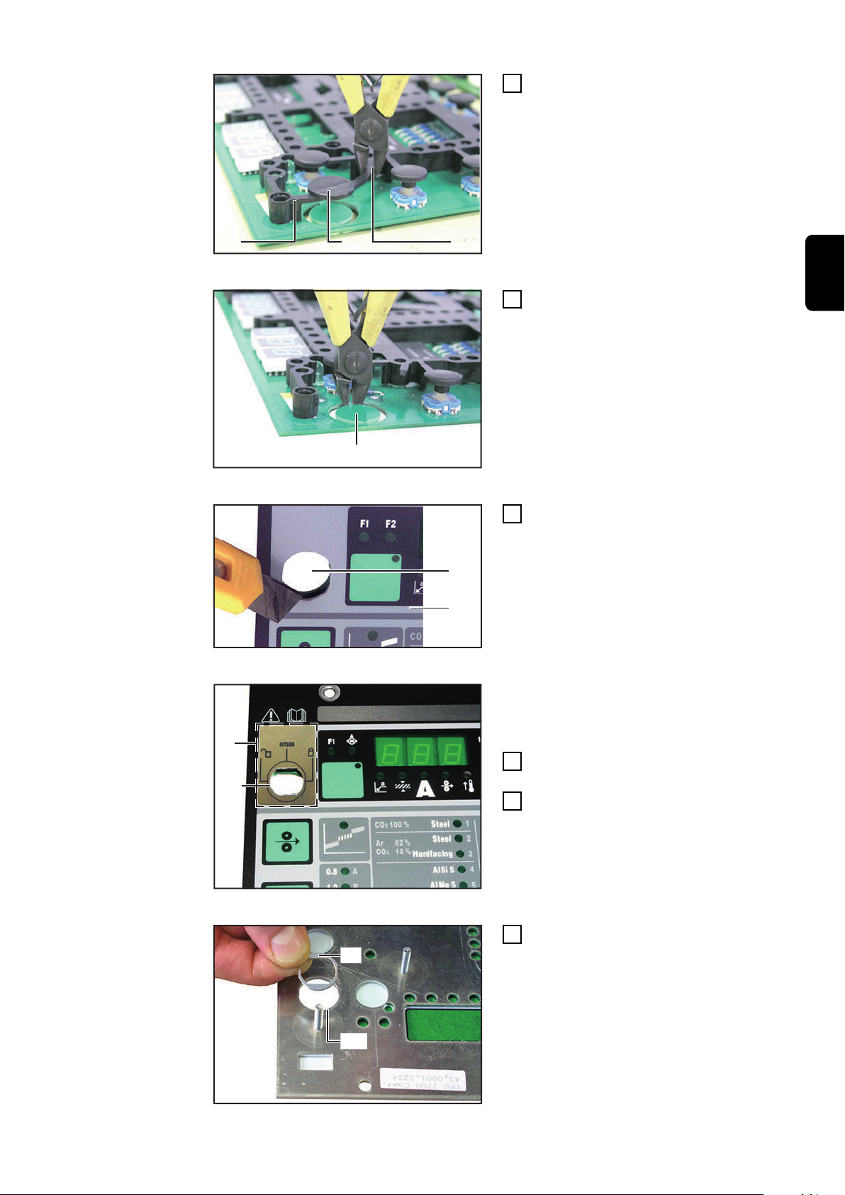
Remove perforated disc (E) on FP
1
25 PCB (C) by detaching the tabs
Removing the perforated disc on the PCB
Cut tab (G) off as completely as
2
possible
Remove perforated disc (F) with
3
tab (G)
EN
Removing the perforated disc on the control panel
Uncovering the hole on the control panel
Uncover the hole (H) on control pa-
4
nel (A) by piercing and cutting the
film on the on the front
IMPORTANT! The procedures from 5
to 7 are only required for the 3-step
keylock switch
Remove the protective film from
5
the sticker provided (7)
Align the protective film with the
6
circle (9) and smooth it down
Positioning the sticker
15
Page 16

(8)
(10)
Place adapter ring (8) in the recess
(C)
(A)
(1)
(3)
(2)
(4)
7
(10) and press lightly to ensure it
adheres properly to the sticker
IMPORTANT! To make things clearer,
the FP (8) 25 PCB is not illustrated.
Attaching the spacer
IMPORTNT! When inserting the keylock switch into the hole (H), align the keylock switch as follows:
turn the key as far as it will go to the left
-
short keylock switch and keylock switch: the key must be in the vertical posi-
-
tion
3-step keylock switch: the key must be in the horizontal position
-
Hold the hexagonal nut (2) between control panel (A) and the FP 25 PCB (C)
8
Feed cable pin 1 (3) and cable pin 3 (4) through control panel (A), hexagonal
9
nut (2) and FP 25 PCB (C)
With the 3-step keylock switch, also feed cable pin 2 through (not illustrated)
Place keylock switch (1) on thread
10
of the hexagonal nut (2)
IMPORTANT! Hold the keylock switch
(1) when tightening the hexagonal nut
(2) so that the keylock switch is kept in
the correct position.
Turn the hexagonal nut (2) and
11
tighten it
Installing the keylock switch
Please skip to the section Completing the keylock switch installation at page
20.
16
Page 17

Variant 2 for in-
(7) (8)(9)
(10)
(12)
(12)
(12) (11)
(11)
(13)
stalling the keylock switch
NOTE!
Risk of damage to the plastic thread on the adjusting dial. Dismantle the adjusting dial carefully.
Dismantling the adjusting dial
Undoing the hexagonal nut
Remove the cap (7) from the adjus-
1
ting dial (8)
Remove hexagonal nut (9) (using a
2
size 10 spanner)
Remove the adjusting dial (8)
3
Remove hexagonal nut (10) (using
4
a size 13 spanner)
EN
Loosening the spacers
Lifting off the FP 25 PCB
Loosen the 9 spacers (12) on the
5
FP 25 PCB (11)
NOTE!
Risk of damage to FP 25 PCB. Do not
bend the FP 25 PCB when lifting it.
Vertically lift off the FP 25 PCB
6
(11), including the separator (13)
17
Page 18

(16)(15) (14)
Cutting out the tab
(17)
(18)
(19)
(7)
(20)
(8)
(21)
Removing the plastic washer
Cut out the tab (14) at positions
7
(15) and (16)
Remove perforated disc (17) by
8
cutting through the attachment
points
Uncovering the hole on the control panel
Positioning the sticker
Uncover the hole (18) on the con-
9
trol panel (19) by piercing and cutting the film on the front
IMPORTANT! The procedures from 10
to 12 are only required for the 3-step
keylock switch
Remove the protective film from
10
the sticker provided (7)
Align the protective film with the
11
circle (20) and smooth it down
18
Attaching the spacer
Place adapter ring (8) in the recess
12
(21) and press lightly to ensure it
adheres properly to the sticker
Page 19

IMPORTANT! When inserting the keylock switch into the hole (18), align the key-
(1)(2)
(11)
(13)
(4)
(3)
(12)
(10)
(7) (8)(9)
lock switch as follows:
turn the key as far as it will go to the left
-
short keylock switch and keylock switch: the key must be in the vertical posi-
-
tion
3-step keylock switch: the key must be in the horizontal position
-
Installing the keylock switch
Fitting the FP 25 PCB
Place keylock switch (1) on thread
13
of the hexagonal nut (2)
IMPORTANT! Hold the keylock switch
(1) when tightening the hexagonal nut
(2) so that the keylock switch is kept in
the correct position.
Turn and tighten hexagonal nut (2)
14
(using a size 22 spanner, for the 3pin keylock switch use a size 19
spanner)
IMPORTANT! Risk of damage to FP 25
PCB. Do not bend the FP 25 PCB
when positioning it.
Feed cable pin 1 (3) and cable pin 3
15
(4) through the FP 25 PCB (11)
With the 3-step keylock switch, also feed cable pin 2 through (not illustrated)
Vertically position the FP 25 PCB
16
(11), including the separator (13)
Secure the FP 25 PCB (11) with
17
the 9 spacers (12)
EN
Tightening the hexagonal nut
Assembling the adjusting dial
Tighten hexagonal nut (10) (using a
18
size 13 spanner)
IMPORTANT! Risk of damage to the
plastic thread on the adjusting dial.
Assemble the adjusting dial carefully.
Attach the adjusting dial (8)
19
Tighten hexagonal nut (9) (using a
20
size 10 spanner)
Put cap (7) in place
21
19
Page 20

Completing the
(C)
(4)
(3)
(3)
(4)
(5)
(B)
(A)
(C)
(D)
keylock switch
installation
Solder cable pin 1 and cable pin 3
Short keylock switch and keylock
switch:
Solder cable pin 1 (3) to X2 on the
1
FP 25 PCB (C)
Solder cable pin 3 (4) to X3 on the
2
FP 25 PCB (C)
3-step keylock switch:
Solder cable pin 1 (3) to X2 on the
1
FP 25 PCB (C)
Solder cable pin 3 (4) to X3 on the
2
FP 25 PCB (C)
Solder cable pin 2 (5) to X6 on the
3
FP 25 PCB (C)
Soldering cable pin 1, pin 2 and pin 3
NOTE!
When inserting the control panel (A) do not pinch, bend or strain the ribbon cable (B).
Connect the ribbon cable on X1 (D)
1
to the FP 25 PCB (C)
Insert control panel (A) into power
2
source and fasten with three
screws
Connecting the ribbon cable and fitting the control panel
20
Page 21

Instructions d'installation
(6)
Généralités Le kit d’installation „Commutateur à clé court“ 4,100,283, „Commutateur à clé“
4,100,317 et „Commutateur à clé 3 niveaux“ 4,100,524 est compatible avec les
sources de courant TS 4000 / 5000 et TPS 2700 / 3200 / 4000 / 5000.
IMPORTANT! Kit d’installation Commutateur à clé 4,100,317 : Avant de
monter le commutateur à clé, mettre
en place la bague d’écartement (6)
fournie du bon côté sur le commutateur à clé.
REMARQUE!
Le commutateur à clé 3 niveaux convient uniquement pour les applications
en intérieur.
Montage du commutateur à clé
FR
Configuration du
système de la
source de courant
Fonction Commutateur à clé
court et Commutateur à clé
Fonction Commutateur à clé 3
niveaux
Version de logiciel 2.56.001 et ultérieures
-
Panneau de commande „Comfort“
-
Numéros de série à partir de 09920551
-
Si la clé est à l’horizontale, les fonctions suivantes sont verrouillées :
Sélection du procédé de soudage avec la ou les touches Procédé
-
Sélection du mode de service avec la ou les touches Mode de service
-
Sélection du matériau d’apport avec la ou les touches Type de matériau
-
Accès au menu Setup avec la touche Store
-
Accès au menu Rectification de job
-
IMPORTANT! Comme sur le panneau de commande de la source de courant, la
fonctionnalité du panneau de commande sur les composants du système est limitée.
Clé en position „Lock“ :
Seules sont actives les fonctions qui sont commandées via une interface ro-
-
bot ou un coupleur de bus de terrain
Toutes les fonctions du panneau de commande sont désactivées
-
Clé en position „Open“ :
Les fonctions qui sont commandées via une interface robot ou un coupleur
-
de bus de terrain sont actives
Sont également réglables toutes les fonctions présentes sur le panneau de
-
commande et qui ne sont pas commandées via l’interface robot ou le coupleur de bus de terrain
21
Page 22

Éléments
(6)
(1)
(4)
(3)
(2)
(1)
(6)
(4)
(3) (2)
(1) (3)
(5)(6)(7)
(8) (2)
(4)
Clé en position „Intern“ :
Les fonctions réglables sur le panneau de commande de la source de courant
-
ou des composants du système sont actives
La commande via une interface robot ou un coupleur de bus de terrain est
-
désactivée
Commutateur à clé court 4,100,283
Commutateur à clé 3 niveaux 4,100,524
Les kits d’installation se composent des pièces suivantes :
(1) Commutateur à clé
(2) Écrou hexagonal
(3) Câble broche 1
(4) Câble broche 3
(5) Câble broche 2
(6) Trousseau de deux clés
(7) Autocollant
(8) Bague d’adaptateur
Commutateur à clé 4,100,317
22
Page 23

Sécurité
(B)
(A)
(C)
(D)
AVERTISSEMENT!
Danger dû à une erreur de manipulation et d'erreur en cours d'opération.
Cela peut entraîner des dommages corporels et matériels graves.
Toutes les fonctions et tous les travaux décrits dans le présent document
▶
doivent uniquement être exécutés par du personnel techniquement qualifié.
Ce document doit être lu et compris dans son intégralité.
▶
Lire et comprendre toutes les consignes de sécurité et la documentation uti-
▶
lisateur de cet appareil et de tous les composants périphériques.
AVERTISSEMENT!
Risque d'électrocution.
Cela peut entraîner des dommages corporels et matériels graves.
Avant d'entamer les travaux, déconnecter tous les appareils et composants
▶
concernés et les débrancher du réseau électrique.
S'assurer que tous les appareils et composants concernés ne peuvent pas
▶
être remis en marche.
Après ouverture de l'appareil, s'assurer, à l'aide d'un appareil de mesure ap-
▶
proprié, que les composants à charge électrique (condensateurs, par ex.)
sont déchargés.
FR
Préparer l’installation du commutateur à clé
REMARQUE!
Respectez les réglementations relatives aux décharges électrostatiques lors de
la manipulation des circuits imprimés. Ces réglementations concernent principalement les éléments suivants adaptés aux décharges électrostatiques :
Emballages
▶
Plans de travail
▶
Sols
▶
Sièges
▶
Possibilités de mise à la terre
▶
IMPORTANT! La garantie ne couvre pas les circuits imprimés manipulés de manière non conforme aux instructions.
REMARQUE!
En démontant le panneau de commande (A), éviter impérativement de coincer, de plier ou de tirer le câble plat
(B).
Démonter le panneau de commande et débrancher le câble plat
Desserrer les trois vis sur le panneau de commande (A)
1
Retirer délicatement le panneau de commande (A)
2
Débrancher le câble plat (B) sur X1 (D) du circuit imprimé FP 25 (C)
3
23
Page 24

Aperçu : Varian-
(C)
(E)
(G)
(F)
(H)
(A)
(7)
(9)
te 1 / Variante 2
IMPORTANT! La section „Variante 1“ se rapporte à une installation rapide du
commutateur à clé. Celle-ci exige néanmoins une grande expérience. Si des incertitudes apparaissent concernant l’exécution sans problème de cette variante
d’installation, veuillez procéder selon les instructions de la section „Variante 2“.
La „Variante 2“ décrit une installation du commutateur à clé qui prend plus de
temps mais est plus facile à réaliser.
Installation du
commutateur à
clé - Variante 1
Enlever le disque protecteur du circuit imprimé
Enlever le disque sur le panneau de commande
Enlever le disque protecteur (E)
1
sur le circuit imprimé FP 25 (C) en
sectionnant les picots de fixation
Couper si possible entièrement le
2
picot de fixation (G)
Retirer le disque protecteur (F)
3
avec ses picots de fixation (G)
Dégager l’orifice sur le panneau de commande
Placer l’autocollant
Dégager l’orifice (H) sur le panneau
4
de commande (A) en perçant et en
découpant l’opercule sur la face
avant
IMPORTANT! Les étapes de 5 à 7 sont
uniquement nécessaires pour le commutateur à clé 3 niveaux.
Retirer le film de protection de
5
l’autocollant fourni (7)
Placer le film de protection sur la
6
ligne circulaire (9) et lisser
24
Page 25

(8)
(10)
Placer la bague d’adaptateur (8)
(C)
(A)
(1)
(3)
(2)
(4)
7
dans l’encoche (10) et appuyer
légèrement, de manière à garantir
une bonne liaison avec l’autocollant
IMPORTANT! Pour un meilleur aperçu,
le circuit imprimé FP 25 ne figure pas
sur l’illustration.
Fixer la rondelle d’écartement
IMPORTANT! Lors de l’insertion du commutateur à clé dans l’orifice (H), Fig. 8,
ajuster le commutateur à clé de la manière suivante :
Tourner la clé jusqu’à la limite vers la gauche
-
Commutateur à clé court et Commutateur à clé : La clé doit se mettre en po-
-
sition verticale
Commutateur à clé 3 niveaux : Le commutateur à clé doit se mettre en posi-
-
tion horizontale
Fixer l’écrou hexagonal (2) entre le panneau de commande (A) et le circuit im-
8
primé FP 25 (C)
Faire passer le câble broche 1 (3) et le câble broche 3 (4) à travers le panneau
9
de commande (A), l’écrou hexagonal (2) et le circuit imprimé FP 25 (C)
Pour le commutateur à clé 3 niveaux, également câble broche 2 (non illustré)
Placer le commutateur à clé (1) sur
10
le filetage de l’écrou hexagonal (2)
IMPORTANT! Maintenir fermement le
commutateur à clé (1) en serrant
l’écrou hexagonal (2) afin de conserver
la bonne position du commutateur à
clé.
FR
Serrer et bloquer l’écrou hexagonal
11
(2)
Montage du commutateur à clé
Consultez également le chapitre Terminer l’installation du commutateur à clé
sur la page 29.
25
Page 26

Installation du
(7) (8)(9)
(10)
(12)
(12)
(12) (11)
(11)
(13)
commutateur à
clé - Variante 2
REMARQUE!
Risque de détérioration du filetage en plastique de la molette de réglage.
Procédez avec précaution lors du démontage de la molette de réglage.
Retirer le capuchon protecteur (7)
1
de la molette de réglage (8)
Desserrer l’écrou hexagonal (9)
2
(ouverture de clé 10)
Enlever la molette de réglage (8)
3
Démonter la molette de réglage
Desserrer l’écrou hexagonal (10)
4
(ouverture de clé 13)
Desserrer l’écrou hexagonal
Débloquer les écarteurs
Soulever le circuit imprimé FP 25
Débloquer les 9 écarteurs (12) sur
5
le circuit imprimé FP 25 (11)
REMARQUE!
Risque de détérioration du circuit imprimé FP 25. Ne pas plier le circuit imprimé FP 25 en le soulevant.
Soulever le circuit imprimé FP 25
6
(11) à la verticale, y compris les
grilles d’écartement (13)
26
Page 27
(16)(15) (14)
Sectionner et ôter les picots de
(17)
(18)
(19)
(7)
(20)
(8)
(21)
7
fixation (14) aux positions (15) et
(16)
Sectionner et ôter les picots de fixation
Enlever le disque protecteur en plastique
Dégager l’orifice sur le panneau de commande
Enlever le disque protecteur (17)
8
en sectionnant les points de fixation
Dégager l’orifice (18) sur le panne-
9
au de commande (19) en perçant
et en découpant l’opercule sur la
face avant
FR
Placer l’autocollant
Fixer la rondelle d’écartement
IMPORTANT! Les étapes 10 à 12 sont
uniquement nécessaires pour le commutateur à clé 3 niveaux.
Retirer le film de protection de
10
l’autocollant fourni (7)
Placer le film de protection sur la
11
ligne circulaire (20) et lisser
Placer la bague d’adaptateur (8)
12
dans l’encoche (21) et appuyer
légèrement, de manière à garantir
une bonne liaison avec l’autocollant
27
Page 28

IMPORTANT! Lors de l’insertion du commutateur à clé dans l’orifice (18), ajuster
(1)(2)
(11)
(13)
(4)
(3)
(12)
(10)
le commutateur à clé de la manière suivante :
Tourner la clé jusqu’à la limite vers la gauche
-
Commutateur à clé court et Commutateur à clé : La clé doit se mettre en po-
-
sition verticale
Commutateur à clé 3 niveaux : Le commutateur à clé doit se mettre en posi-
-
tion horizontale
Placer le commutateur à clé (1) sur
13
le filetage de l’écrou hexagonal (2)
IMPORTANT! Maintenir fermement le
commutateur à clé (1) en serrant
l’écrou hexagonal (2) afin de conserver
la bonne position du commutateur à
clé.
Serrer et bloquer l’écrou hexagonal
14
(2) (ouverture de clé 22, pour com-
Montage du commutateur à clé
mutateur à clé 3 pôles : ouverture
de clé 19)
IMPORTANT! Risque de détérioration
du circuit imprimé FP 25. Ne pas plier
le circuit imprimé FP 25 en le mettant
en place.
Sechskant-Mutter festschrauben
Serrer l’écrou hexagonal
Faire passer le câble broche 1 (3)
15
et le câble broche 3 (4) à travers le
circuit imprimé FP 25 (11)
Pour le commutateur à clé 3 niveaux, également câble broche 2
(non illustré)
Mettre en place le circuit imprimé
16
FP 25 (11) à la verticale, y compris
les grilles d’écartement (13)
Fixer les 9 écarteurs (12) sur le cir-
17
cuit imprimé FP 25 (11)
Serrer l’écrou hexagonal (10) (ou-
18
verture de clé 13)
28
Page 29

(7) (8)(9)
Mise en place de la molette de réglage
(C)
(4)
(3)
(3)
(4)
(5)
IMPORTANT! Risque de détérioration
du filetage en plastique de la molette
de réglage. Procédez avec précaution
lors du montage de la molette de
réglage.
Mettre en place la molette de
19
réglage (8)
Serrer l’écrou hexagonal (9) (ouver-
20
ture de clé 10)
Mettre en place le capuchon pro-
21
tecteur (7)
FR
Terminer l’installation du commutateur à clé
Souder par brasage le câble broche 1 et le câble
broche 3
Souder par brasage le câble broche 1, broche 2
et broche 3
Commutateur à clé court et Commutateur à clé :
Souder par brasage le câble bro-
1
che 1 (3) sur X2 sur le circuit imprimé FP 25 (C)
Souder par brasage le câble bro-
2
che 3 (4) sur X3 sur le circuit imprimé FP 25 (C)
Commutateur à clé 3 niveaux :
Souder par brasage le câble bro-
1
che 1 (3) sur X2 sur le circuit imprimé FP 25 (C)
Souder par brasage le câble bro-
2
che 3 (4) sur X3 sur le circuit imprimé FP 25 (C)
Souder par brasage le câble bro-
3
che 2 (5) sur X6 sur le circuit imprimé FP 25 (C)
REMARQUE!
En mettant en place le panneau de commande (A), éviter impérativement de coincer, de plier ou de tirer le câble plat (B).
29
Page 30

(B)
(A)
(C)
(D)
Brancher le câble plat et monter le panneau de
commande
Brancher le câble plat sur X1 (D)
1
sur le circuit imprimé FP 25 (C)
Insérer le panneau de commande
2
(A) dans la source de courant et fixer au moyen des trois vis
30
Page 31

FR
31
Page 32

Fronius International GmbH
Froniusstraße 1
4643 Pettenbach
Austria
contact@fronius.com
www.fronius.com
Under www.fronius.com/contact you will find the adresses
of all Fronius Sales & Service Partners and locations.
spareparts.fronius.com
SPAREPARTS
ONLINE
 Loading...