

Page 1

/ Battery Charging Systems / Welding Technology / Solar Electronics
KD Digital/LocalNet
Einbauanleitung
WIG/HAP-Systemerweiterung
DEEN
Installation instructions
TIG/HAP system add-on
42,0410,1203 004-24072019
Page 2

Page 3

Allgemeines
WARNUNG! Fehlerhaft durchgeführte Arbeiten können schwerwiegende Sach-
und Personenschäden verursachen. Nachfolgend beschriebene Tätigkeiten
dürfen nur von geschultem Fachpersonal durchgeführt werden! Beachten Sie die
Sicherheitsvorschriften in der Bedienungsanleitung der Stromquelle.
WARNUNG! Ein elektrischer Schlag kann tödlich sein. Vor Öffnen des Gerätes:
- Netzschalter der Stromquelle in Stellung „Off“ schalten
- Stromquelle vom Netz trennen
Allgemeines
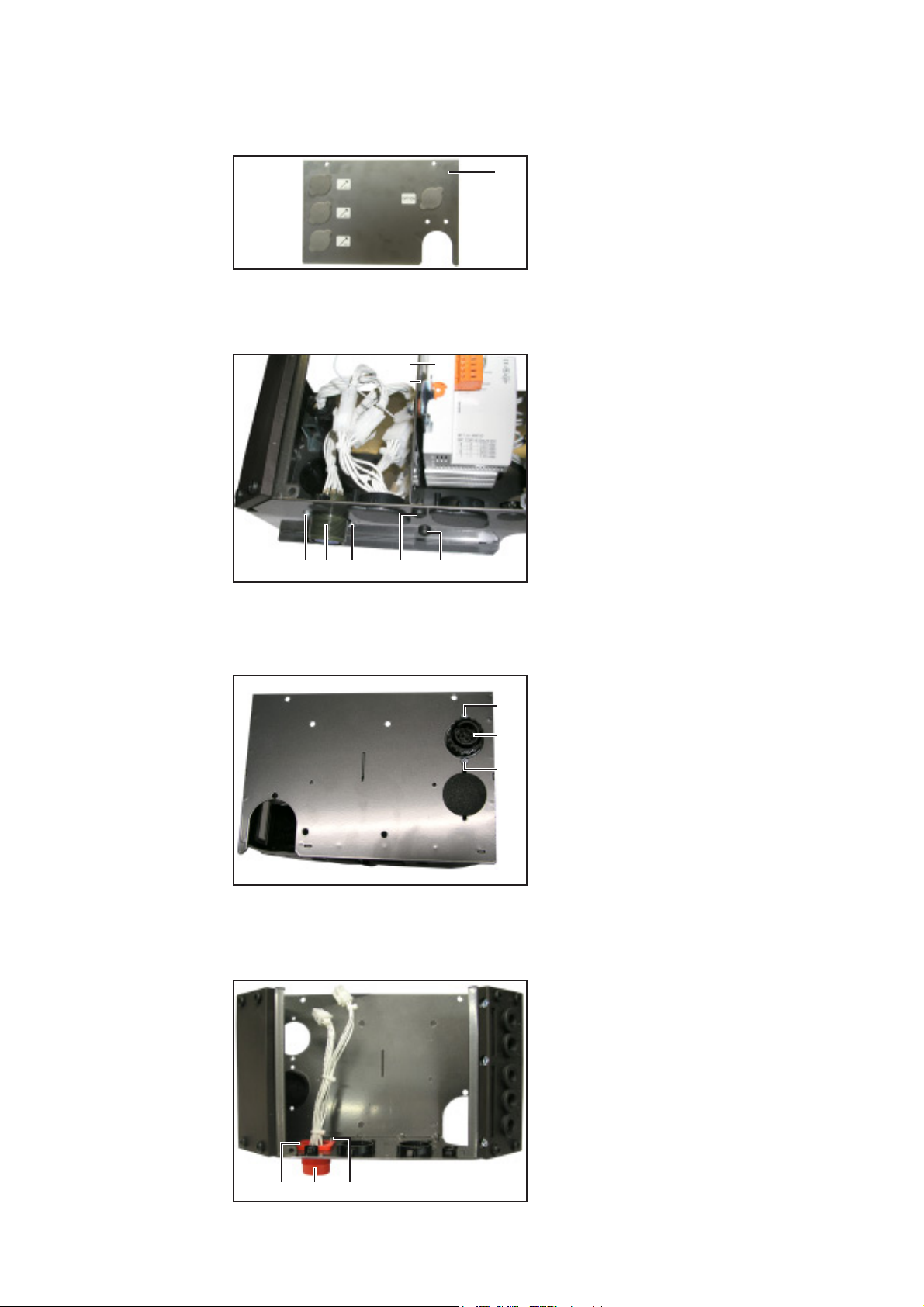
Bauteile Das Einbauset KD Digital/LocalNet (4,100,456) besteht aus folgenden Bauteilen:
(6)
(5)
DE
(4)
(3)
(2)
Abb.1 Lieferumfang
(1) Print SNT 3
(2) Print NT 60
(3) 2 Anschlussbuchsen LocalNet
(4) Kabelbaum 4-polig
(5) Kabelbaum 6-polig „Buchse-Stecker“
(6) Kabelbaum 6-polig „Buchse-Buchse“
(7) 5 Kabelbinder
(1) (12)
(7)
(8)
(9)
(26)
(10)
(11)
(8) 4 Schrauben
(9) 5 Distanzen kurz
(10)8 Distanzen lang
(11) 1 Messingdistanz
(12)2 Abdeckkappen
(26)4 Gewindebolzen
Einbauvarianten Nachfolgend ist der Einbau auf zwei Arten erklärt:
- In der Stromquelle
- Im Feldbus-Koppler, wenn vorhanden
1
Page 4

KD Digital/LocalNet in Stromquelle einbauen
Vorbereitung 1. Rechtes Seitenteil abmontieren
(14)
(15)
Abb.2 Blindabdeckungen entfernen
Anschlussbuchsen LocalNet
montieren
(9) (3)(8)(9) (16)
(13)
2. Rückfront (13) abmontieren
3. Blindabdeckungen an den Durchführungen (14) und (15) entfernen
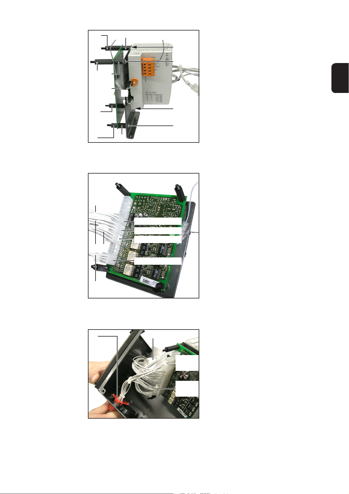
Abb.3 Anschlussbuchsen LocalNet und Distanzen montieren
HINWEIS! Bei der Montage der Anschlussbuchsen LocalNet (3) darauf achten,
dass sich der Führungssteg (16) oben befindet
1. Anschlussbuchsen LocalNet (3) jeweils mit zwei beiliegenden Schrauben (8) montieren
2. An den Anschlussbuchsen LocalNet (3) die beiliegenden Abdeckkappen (12) aufsetzen
3. 4 Distanzen kurz (9) an der Rückfront festschrauben
2
Page 5

Print SNT3
montieren
(10)
(1)
(10)
DE
(3)
Output C
(6-polig)
Output C
(4-polig)
Untere Anschlussbuchse anstecken
(10)
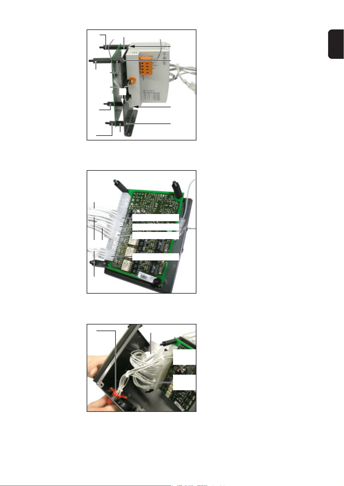
Abb.4 Print SNT3 montieren und obere Anschlussbuchse anstecken
(9)
1. Print SNT3 (1) auf die 4 Distanzen kurz (9) aufsetzen
HINWEIS! Beim Befestigen des Prints SNT3 (1) darauf achten, dass sich die
Distanz kurz (9) rechts unten befindet.
2. Print SNT3 (1) mittels 3 Distanzen lang (10) und einer Distanz kurz (9) montieren
Die obere Anschlussbuchse LocalNet (3) wie folgt anschließen:
3. 4-poligen Kabelbaum an den Anschluss Output C (4-polig) anstecken
4. 6-poligen Kabelbaum an den Anschluss Output C (6-polig) anstecken
Output B
(6-polig)
Abb.5 Untere Anschlussbuchse anstecken
Die untere Anschlussbuchse LocalNet (3) wie folgt anschließen:
1. 4-poligen Kabelbaum an den Anschluss Output B (4-polig) anstecken
2. 6-poligen Kabelbaum an den Anschluss Output B (6-polig) anstecken
3
(3)
Output B
(4-polig)
Page 6

Kabelbäume
anstecken
Output A
Input (6-polig)
Input (4-polig)
(4) (6) (5)
Print NT60 montieren
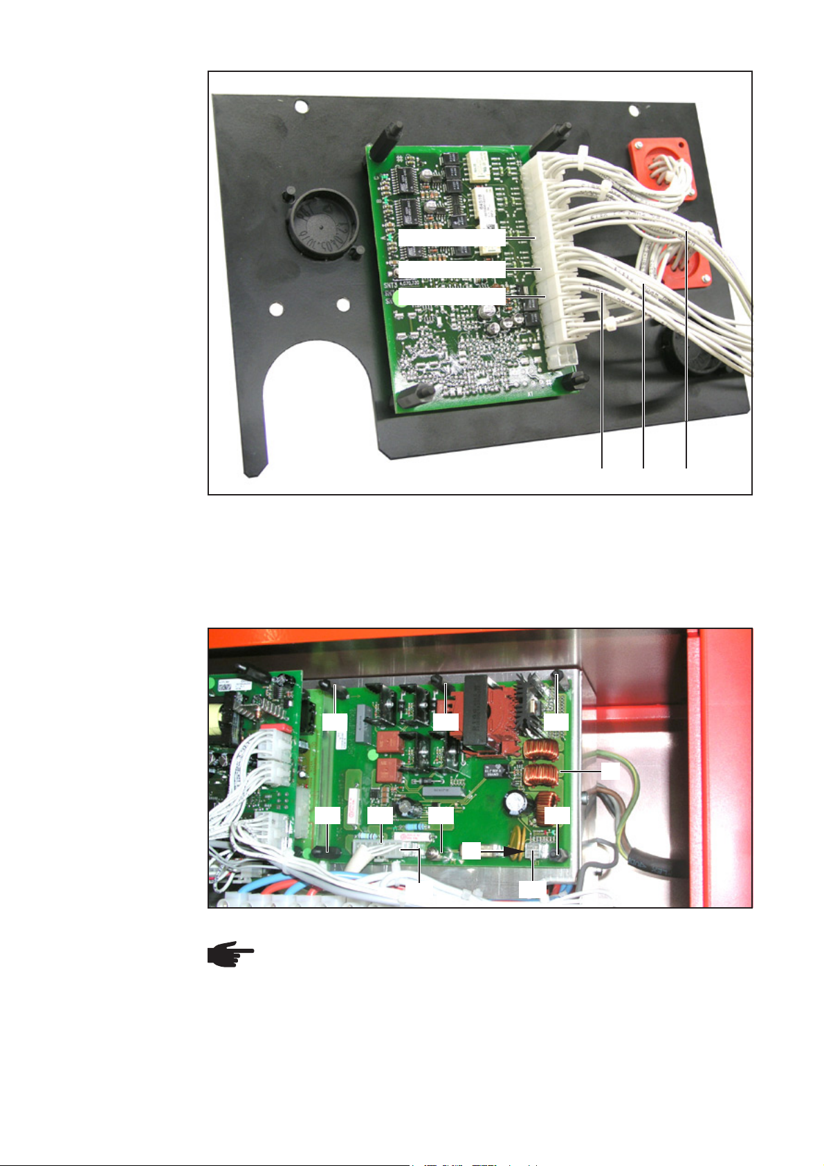
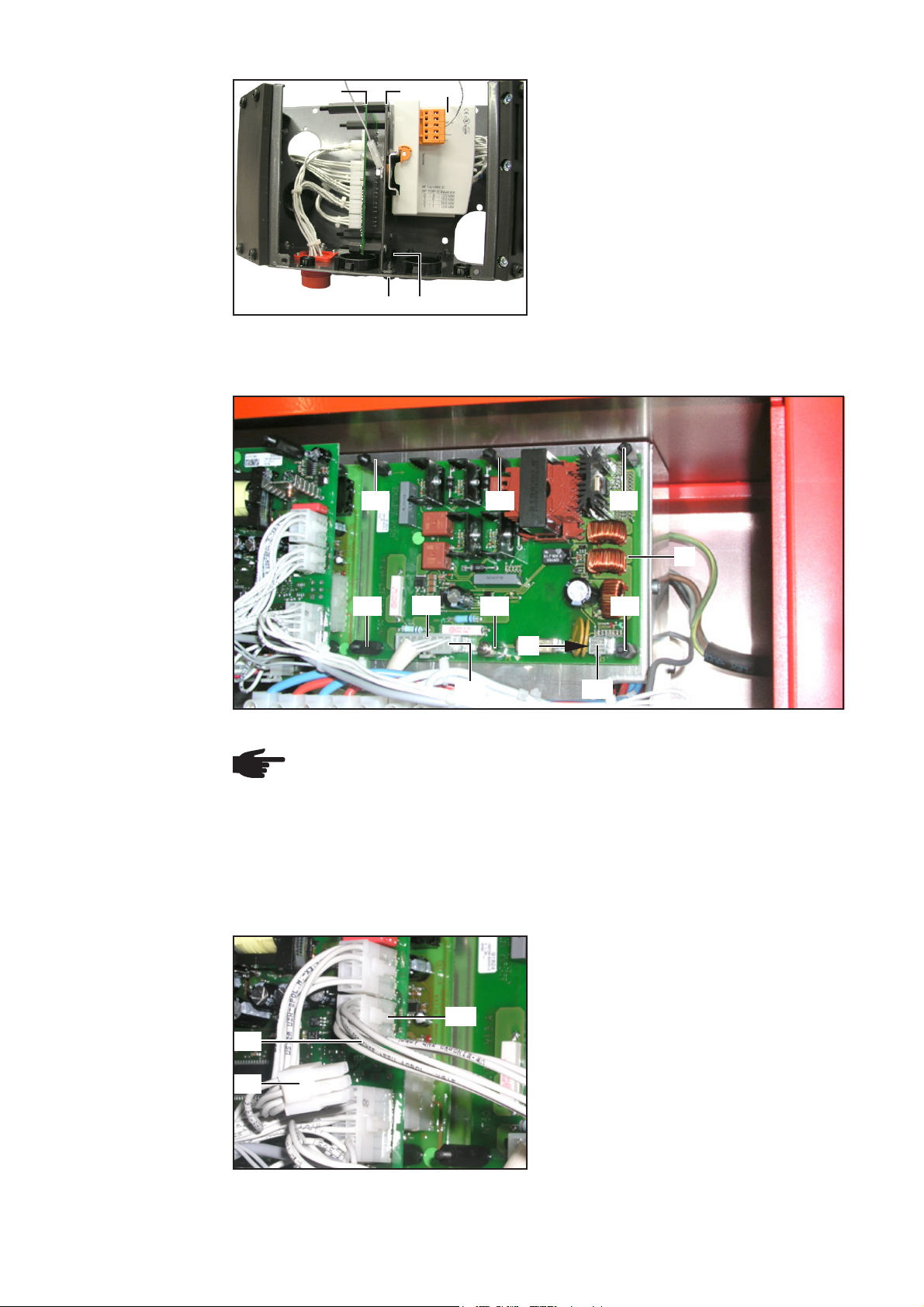
Abb.6 Kabelbäume anstecken
1. Kabelbaum 6-polig „Buchse-Stecker“ (5) an den Anschluss Output A anstecken
2. Kabelbaum 4-polig „Buchse-Buchse“ (4) an den Anschluss Input (4-polig) anstecken
3. Kabelbaum 6-polig „Buchse-Buchse“ (6) an den Anschluss Input (6-polig) anstecken
(10) (10) (10)
(2)
(10)
(17)
(11)
(10)
(4)
X2
X1
Abb.7 Print NT 60 montieren und anschließen
HINWEIS! Auf korrekte Position der Messingdistanz (11) Abb.3 achten.
1. Print NT 60 (2) mittels 5 Distanzen lang (10) und einer Messingdistanz (11) montieren
2. Kabelbaum 4-polig „Buchse-Buchse“ (4) am Print NT 60: X1 anstecken
3. Vom 16-poligen Molexstecker (17) den Blindstecker (nicht abgebildet) abstecken
4. 16-poligen Molexstecker (17) am Print NT 60: X2 anstecken
4
Page 7

Print UST anschließen
(6)
(18)
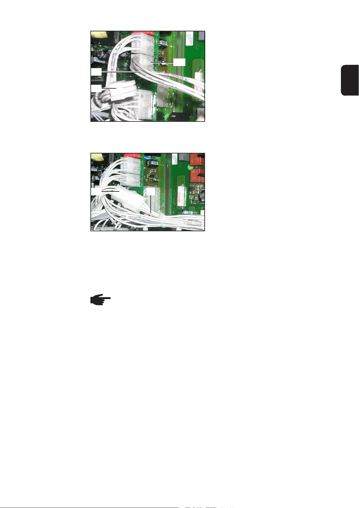
Abb.8 Print UST anschließen
X9
1. Rückfront montieren
2. 6-poligen Molexstecker (18) am Print
UST: X9 abstecken
3. Kabelbaum 6-polig „Buchse-Buchse“
(6) am Print UST: X9 anstecken
DE
Kabelbaum
„Buchse-Stecker“
anschließen
Abschließende
Tätigkeiten
Betrieb eines KDVorschubs
(18)
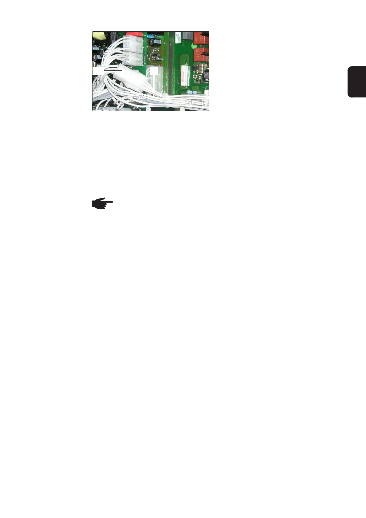
Abb.9 Kabelbaum anstecken
(5)
1. Rechtes Seitenteil montieren
HINWEIS! Für den Betrieb eines digitalen Kaltdraht - Vorschubsystems ist eine
zusätzliche Versorgungsspannung erforderlich. Diese Versorgungsspannung
steht nur an den LocalNet Anschlüssen auf der Rückseite des Geräts zur Verfügung.
1. Kabelbaum 6-polig „Buchse-Stecker“
(5) am zuvor abgesteckten Molexstecker (18) anstecken
2. Kabel mittels beiliegenden Kabelbindern fixieren
5
Page 8
KD Digital/LocalNet in Feldbus-Koppler einbauen
Vorbereitung 1. Rechtes Seitenteil abmontieren
Abb.10Rückfront abmontieren
Feldbus-Koppler
vorbereiten
(23)
(22)
(13)
2. Rückfront (13) abmontieren
1. Feldbuskoppler demontieren
Am Feldbus-Koppler
2. Deckel demontieren
3. Alle Molex-Steckverbindungen lösen
und zugehörige Kabelbäume entfernen
4. Zwei Schrauben (19) lösen und bestehende Anschlussbuchse LocalNet (20)
aus Metall entnehmen
5. Zwei Schrauben (21) lösen und Trennblech (22) inklusive Interface (23)
(19) (19) (21) (21)(20)
Abb.11Komponenten demontieren
entnehmen
Bestehende
Anschlussbuchse
entfernen
Anschlussbuchse
LocalNet montieren
Abb.12Anschlussbuchse Feldbus-Koppler
entfernen
(24)
(25)
(24)
1. 2 Schrauben (24) lösen und Anschlussbuchse Feldbus-Koppler (25)
entnehmen
1. Anschlussbuchse LocalNet (3) aus
Kunststoff mittels 2 Schrauben (8)
montieren
(3) (8)(8)
Abb.13Anschlussbuchse LocalNet montieren
6
Page 9
Print SNT3 am
Trennblech
montieren
(10)
(10)
(10)
(9)
(2)
(9)
(9)
(26)
(26)
1. 4 Distanzen kurz (9) mittels 4 Gewindebolzen (26) befestigen
2. Print SNT3 (2) auf Distanzen kurz (9)
aufsetzen
3. Print SNT3 (2) mittels 3 Distanzen lang
(10) und einer Distanz kurz (9) befestigen
DE
Kabelbäume am
Print SNT3 anstecken
(10)
(9)
Abb.14Print SNT3 montieren
(9)
(4)
Input (4-polig)
Input (6-polig)
Output A (6-polig)
(5)(6)
Output C (6-polig)
(26)
(26)
1. Kabelbaum 4-polig „Buchse-Buchse“
(4) an den Anschluss Input (4-polig)
anstecken
2. Kabelbaum 6-polig „Buchse-Buchse“
(6) an den Anschluss Input (6-polig)
anstecken
3. Kabelbaum 6-polig „Buchse-Stecker“
(5) an den Anschluss Output A (6-polig)
anstecken
4. Kabelbaum 6-polig (27) vom Interface
an den Anschluss Output C (6-polig)
anstecken
Anschlussbuchse
LocalNet anstecken und Kabelbäume verlegen
(27)
Abb.15Kabelbäume anstecken
(3) (28)
Output B
(4-polig)
Output B
(6-polig)
Abb.16Anschlussbuchse LocalNet anstecken
Anschlussbuchse LocalNet (3) wie folgt
anschließen:
1. 4-poligen Kabelbaum an den Anschluss
Output B (4-polig) anstecken
2. 6-poligen Kabelbaum an den Anschluss
Output B (6-polig) anstecken
3. Die übrigen bereits angesteckten
Kabelbäume durch die Öffnung (28)
führen
7
Page 10

Trennblech für
Interface montieren
Print NT60 montieren
(21) (21)
Abb.17 Trennblech montieren
(10) (10) (10)
(22)(1) (23)
1. Trennblech (22) inklusive Interface (23)
und Print SNT3 (1) mit 2 Schrauben
(21) montieren
2. Feldbus-Koppler anstelle der Rückfront
montieren
Print UST anschließen
(2)
(10)
(17)
(11)
(10)
(4)
X2
Abb.18 Print NT 60 montieren und anschließen
X1
HINWEIS! Auf korrekte Position der Messingdistanz (11) Abb.3 achten.
1. Print NT 60 (2) mittels 5 Distanzen lang (10) und einer Messingdistanz (11) montieren
2. Kabelbaum 4-polig „Buchse-Buchse“ (4) am Print NT 60: X1 anstecken
3. Vom 16-poligen Molexstecker (17) den Blindstecker (nicht abgebildet) abstecken
4. 16-poligen Molexstecker (17) am Print NT 60: X2 anstecken
1. 6-poligen Molexstecker (18) am Print
UST: X9 abstecken
2. Kabelbaum 6-polig „Buchse-Buchse“
(6) am Print UST: X9 anstecken
X9
(6)
(18)
Abb.19 Print UST anschließen
8
Page 11

Kabelbaum
„Buchse-Stecker“
anschließen
(18) (5)
Abb.20 Kabelbaum anstecken
1. Kabelbaum 6-polig „Buchse-Stecker“
(5) am zuvor abgesteckten Molexstecker (18) anstecken
2. Kabel mittels beiliegenden Kabelbindern fixieren
DE
Abschließende
Tätigkeiten
Betrieb eines KDVorschubs
1. An der Stromquelle linkes Seitenteil montieren
2. Am Feldbus-Koppler Deckel montieren
HINWEIS! Für den Betrieb eines digitalen Kaltdraht - Vorschubsystems ist eine
zusätzliche Versorgungsspannung erforderlich. Diese Versorgungsspannung
steht nur an den LocalNet Anschlüssen auf der Rückseite des Geräts zur Verfügung.
9
Page 12

10
Page 13

General
WARNING! Operating the equipment incorrectly can cause serious injury and
damage. The following activities must only be carried out by trained and qualified
personnel! Take note of the safety rules in the power source operating instructions.
WARNING! An electric shock can be fatal. Before opening the machine:
- Switch the power source mains switch to the „Off“ position
- Unplug power source from the mains
General remarks
Components The KD Digital/LocalNet (4,100,456) installation set consists of the following compon-
ents:
(6)
(5)
EN
(4)
(3)
(2)
Fig. 1 Scope of supply
(1) SNT 3 PCB
(2) NT 60 PCB
(3) 2 LocalNet connection sockets
(4) 4-pin cable harness
(5) „Socket-plug“ 6-pin cable harness
(6) „Socket-socket“ 6-pin cable harness
(7) 5 cable ties
(1) (12)
(7)
(8)
(9)
(26)
(10)
(11)
(8) 4 screws
(9) 5 spacers (short)
(10)8 spacers (long)
(11) 1 brass spacer
(12)2 caps
(26)4 thread bolts
Installation
variants
Two types of installation are described below:
- In the power source
- In the field bus coupler, if available
1
Page 14

Installing KD Digital/LocalNet in the power source
Preparations 1. Remove the right side panel
(14)
(15)
Fig. 2 Removing the blanking covers
Fitting the LocalNet connection
sockets
(9) (3)(8)(9) (16)
(13)
2. Remove the back panel (13)
3. Remove the blanking covers from
bushings (14) and (15)
Fig. 3 Fitting LocalNet connection sockets and spacers
NOTE! When fitting the LocalNet connection sockets (3), ensure that the guide
bar (16) is at the top
1. Fit each LocalNet connection socket (3) using the two screws supplied (8)
2. Place the enclosed caps (12) on the LocalNet connection sockets (3)
3. Screw 4 short spacers (9) onto back panel
2
Page 15

Fitting the SNT3
PCB
(10)
(1)
(10)
(3)
Output C
(6-pin)
EN
Output C
(4-pin)
Connecting the
lower connection
socket
(10)
Fig. 4 Fitting the SNT3 PCB and connecting the upper connection socket
1. Place SNT3 PCB (1) onto the 4 short spacers (9)
NOTE! When fastening the SNT3 PCB (1) ensure that the short spacer (9) is
bottom right.
2. Fit SNT3 PCB (1) using 3 long spacers (10) and one short spacer (9)
Connect the upper LocalNet connection socket (3) as follows:
3. Plug 4-pin cable harness into Output C connection (4-pin)
4. Plug 6-pin cable harness into Output C connection (6-pin)
(9)
Output B
(6-pin)
Fig. 5 Connecting the lower connection socket
Connect the lower LocalNet connection socket (3) as follows:
1. Plug 4-pin cable harness into Output B connection (4-pin)
2. Plug 6-pin cable harness into Output B connection (6-pin)
3
(3)
Output B
(4-pin)
Page 16
Plugging in the
cable harnesses
Output A
Input (6-pin)
Input (4-pin)
(4) (6) (5)
Fitting the NT60
PCB
Fig. 6 Plugging in the cable harnesses
1. Plug 6-pin „socket-plug“ cable harness (5) into Output A connection
2. Plug 4-pin „socket-socket“ cable harness (4) into Input connection (4-pin)
3. Plug 6-pin „socket-socket“ cable harness (6) into Input connection (6-pin)
(10) (10) (10)
(2)
(10)
(17)
(11)
(10)
(4)
X2
X1
Fig. 7 Fitting and connecting the NT 60 PCB
NOTE! Ensure that brass spacer (11) is in correct position, as shown in Fig. 3.
1. Fit NT 60 PCB (2) using 5 long spacers (10) and one brass spacer (11)
2. Plug 4-pin „socket-socket“ cable harness (4) into NT 60 PCB (X1)
3. Unplug dummy plug (not illustrated) from 16-pin Molex plug (17)
4. Plug 16-pin Molex plug (17) into NT 60 PCB (X2)
4
Page 17
Connecting the
UST PCB
(6)
X9
1. Fit back panel
2. Unplug 6-pin Molex plug (18) from UST
PCB (X9)
3. Plug 6-pin „socket-socket“ cable
harness (6) into UST PCB (X9)
Connecting the
„socket-plug“
cable harness
(18)
Fig. 8 Connecting the UST PCB
(18)
Fig. 9 Plugging in the cable harness
(5)
EN
1. Plug 6-pin „socket-plug“ cable harness
(5) into previously disconnected Molex
plug (18)
2. Bind cables together with cable ties
supplied
Finally activities 1. Fit right side panel
Using a cold wire
feeder
NOTE! An additional supply voltage is required if you want to use a digital cold
wire feeder. This supply voltage is only available on the LocalNets ports on the
rear of the device.
5
Page 18

Installing KD Digital/LocalNet in the field bus coupler
Preparations 1. Remove the right side panel
Fig. 10 Removing the back panel
Preparing the
field bus coupler
(19) (19) (21) (21)(20)
Fig.11 Dismantling the components
(23)
(22)
(13)
2. Remove the back panel (13)
1. Remove field bus coupler
On the field bus coupler
2. Remove cover
3. Undo all Molex plug connections and
remove accompanying cable harnesses
4. Undo two screws (19) and remove
existing metal LocalNet connection
socket (20)
5. Undo two screws (21) and remove
divider (22), including interface (23)
Removing the
existing connection socket
Fitting the LocalNet connection
socket
Fig. 12 Removing field bus coupler connection
socket
(24)
(25)
(24)
1. Undo 2 screws (24) and remove field
bus coupler connection socket (25)
1. Fit plastic LocalNet connection socket
(3) using two screws (8)
(3) (8)(8)
Fig. 13 Fitting the LocalNet connection socket
6
Page 19
Fitting SNT3 PCB
to divider
(10)
(10)
(10)
(9)
(2)
(9)
(9)
(26)
(26)
1. Fasten 4 short spacers (9) with 4
thread bolts (26)
2. Place SNT3 PCB (2) onto short
spacers (9)
3. Fasten SNT3 PCB (2) with 3 long
spacers (10) and one short spacer (9)
EN
Plugging cable
harnesses into
SNT3 PCB
(10)
(9)
Fig. 14 Fitting the SNT3 PCB
(9)
(4)
Input (4-pin)
Input (6-pin)
Output A (6-pin)
(5)(6)
Output C (6-pin)
(26)
(26)
1. Plug 4-pin „socket-socket“ cable
harness (4) into Input connection (4pin)
2. Plug 6-pin „socket-socket“ cable
harness (6) into Input connection (6pin)
3. Plug 6-pin „socket-plug“ cable harness
(5) into Output A connection (6-pin)
4. Plug interface 6-pin cable harness (27)
into Output C connection (6-pin)
Connecting the
LocalNet connection socket and
routing the cable
harnesses
(27)
Fig. 15 Plugging in the cable harnesses
(3) (28)
Output B
(4-pin)
Output B
(6-pin)
Fig. 16 Connecting the LocalNet connection
socket
Connect LocalNet connection socket (3) as
follows:
1. Plug 4-pin cable harness into Output B
connection (4-pin)
2. Plug 6-pin cable harness into Output B
connection (6-pin)
3. Feed the remaining plugged-in cable
harnesses through opening (28)
7
Page 20
Fitting the divider
for the interface
Fitting the NT60
PCB
Fig. 17 Fitting the divider
(10) (10) (10)
(22)(1) (23)
(21) (21)
1. Fit divider (22), including interface (23)
and SNT3 PCB (1) with 2 screws (21)
2. Fit field bus coupler instead of the back
panel
Connecting the
UST PCB
(2)
(10)
(17)
(11)
(10)
(4)
X2
Fig. 18 Fitting and connecting the NT 60 PCB
X1
NOTE! Ensure that brass spacer (11) is in correct position, as shown in Fig. 3.
1. Fit NT 60 PCB (2) using 5 long spacers (10) and one brass spacer (11)
2. Plug 4-pin „socket-socket“ cable harness (4) into NT 60 PCB (X1)
3. Unplug dummy plug (not illustrated) from 16-pin Molex plug (17)
4. Plug 16-pin Molex plug (17) into NT 60 PCB (X2)
1. Unplug 6-pin Molex plug (18) from UST
PCB (X9)
2. Plug 6-pin „socket-socket“ cable
harness (6) into UST PCB (X9)
X9
(6)
(18)
Fig. 19 Connecting the UST PCB
8
Page 21
Connecting the
„socket-plug“
cable harness
1. Plug 6-pin „socket-plug“ cable harness
(5) into previously disconnected Molex
plug (18)
(18) (5)
EN
Fig. 20 Plugging in the cable harness
Finally activities
Using a cold wire
feeder
1. Bind cables together with cable ties
supplied
2. Fit left side panel to power source
3. Fit cover to field bus coupler
NOTE! An additional supply voltage is required if you want to use a digital cold
wire feeder. This supply voltage is only available on the LocalNets ports on the
rear of the device.
9
Page 22

10
Page 23

Page 24

FRONIUS INTERNATIONAL GMBH
Froniusstraße 1, A-4643 Pettenbach, Austria
E-Mail: sales@fronius.com
www.fronius.com
Under www.fronius.com/contact you will find the addresses
of all Fronius Sales & Service Partners and locations
 Loading...