

Page 1

/ Battery Charging Systems / Welding Technology / Solar Electronics
Interface Slave BIAS 300 Plasma
Bedienungsanleitung
Interface
DEEN
Operating Instructions
Interface
42,0410,1279 002-29032012
Page 2

Page 3

Sehr geehrter Leser
DE
Einleitung
Wir danken Ihnen für Ihr entgegengebrachtes Vertrauen und gratulieren Ihnen zu Ihrem
technisch hochwertigen Fronius Produkt. Die vorliegende Anleitung hilft Ihnen, sich mit
diesem vertraut zu machen. Indem Sie die Anleitung sorgfältig lesen, lernen Sie die
vielfältigen Möglichkeiten Ihres Fronius-Produktes kennen. Nur so können Sie seine
Vorteile bestmöglich nutzen.
Bitte beachten Sie auch die Sicherheitsvorschriften und sorgen Sie so für mehr Sicherheit am Einsatzort des Produktes. Sorgfältiger Umgang mit Ihrem Produkt unterstützt
dessen langlebige Qualität und Zuverlässigkeit. Das sind wesentliche Voraussetzungen
für hervorragende Ergebnisse.
ud_fr_st_et_00491 01/2012
Page 4

Page 5

Inhaltsverzeichnis
Allgemeines................................................................................................................................................... 2
Sicherheit ................................................................................................................................................. 2
Gerätekonzept.......................................................................................................................................... 2
Anschlüsse ............................................................................................................................................... 2
Interface Slave aus Spannungsquelle BIAS 300 Plasma ausbauen ............................................................. 3
Sicherheit ................................................................................................................................................. 3
Vorbereitung............................................................................................................................................. 3
Kabel und Stecker abschließen................................................................................................................ 4
Interface Slave aus Spannungsquelle BIAS 300 Plasma ausbauen ........................................................ 6
Interface Slave in Spannungsquelle BIAS 300 Plasma einbauen ................................................................. 8
Sicherheit ................................................................................................................................................. 8
Voraussetzung für den Einbau eines Interfaces....................................................................................... 8
Interface Slave in Spannungsquelle BIAS 300 Plasma einbauen ............................................................ 8
Kabel und Stecker anschließen.............................................................................................................. 10
Abschließende Tätigkeiten ......................................................................................................................11
Inbetriebnahme ........................................................................................................................................... 12
Allgemeines ........................................................................................................................................... 12
Voraussetzung für den Betrieb der Spannungsquellen in Parallelkonfiguration ..................................... 12
Slave-Spannungsquelle mit Master-Spannungsquelle verbinden........................................................... 12
Netzkabel anschließen ........................................................................................................................... 13
Einstellungen im Betrieb ........................................................................................................................ 13
DE
Steuerung externer Komponenten .............................................................................................................. 14
Allgemeines ........................................................................................................................................... 14
Steckerbelegung von Anschluss Arc Signals ......................................................................................... 14
Technische Daten........................................................................................................................................ 15
Sonderspannung .................................................................................................................................... 15
Technische Daten .................................................................................................................................. 15
1
Page 6

Allgemeines
Sicherheit
Gerätekonzept
Anschlüsse
WARNUNG! Fehlbedienung kann schwerwiegende Personen- und Sachschä-
den verursachen. Die angeführten Tätigkeiten erst durchführen, wenn diese
Bedienungsanleitung und folgende Dokumente vollständig gelesen und verstanden wurden:
- Die Bedienungsanleitung der Spannungsquelle, insbesondere das Kapitel
„Sicherheitsvorschriften“.
- Sämtliche Bedienungsanleitungen der gesamten Anlage
Das Interface Slave BIAS 300 Plasma ist eine Schnittstelle zum Anbinden der Spannungsquelle BIAS 300 Plasma an eine Master-Spannungsquelle in Parallelkonfiguration.
HINWEIS! Für den Betrieb von Spannungsquelle und Interface muss das
Interface an der Spannungsquelle montiert sein!
(3)
(2)
(4)
(5)
(6)
(1)
Abb.1 Interface Slave BIAS 300 Plasma, montiert auf der Spannungsquelle BIAS 300 Plasma
(1) Netzstecker
6-poliger Harting-Stecker zum Anschluss des Netzkabels
(2) Anschluss Arc Bus
zum Anschluss eines eigenen Bussystems für schnelles Abschalten
(3) Anschluss Arc Signals
14-polige Amphenolbuchse zum
Anschluss der Lichtbogen-Signale
(4) Anschluss Arc Bus
zum Anschluss eines eigenen Bussystems für schnelles Abschalten
(5) Blindabdeckung
(6) Anschluss LocalNet
standardisierte Anschlussbuchse für
Systemerweiterungen (z.B. Fernbedienung, etc.)
(7) Anschluss LHSB
zur Datenübertragung bei Parallelkonfiguration
(8) Masseanschluss
(9) Anschluss Arc In
Anschlussbuchse für LichtwellenLeiter zur Übertragung des Sicherheitsfunktions-Signals von einem
externen Gerät oder einer externen
Steuerung (siehe Sicherheitsfunktion
aktivieren / deaktivieren in der Bedienungsanleitung der Spannungsquelle)
(10) Anschluss Arc Out
Anschlussbuchse zum Anschluss der
Lichtbogen-Signale über LichtwellenLeiter
(7)
(8)
(9)
(10)
2
Page 7

Interface Slave aus Spannungsquelle BIAS 300 Plas-
WARNUNG! Fehlerhaft durchgeführte Arbeiten können schwerwiegende Sach-
und Personenschäden verursachen. Nachfolgend beschriebene Tätigkeiten
dürfen nur von geschultem Fachpersonal durchgeführt werden! Beachten Sie
die Sicherheitsvorschriften .
ma ausbauen
Sicherheit
WARNUNG! Ein elektrischer Schlag kann tödlich sein. Vor Öffnen der Span-
nungsquelle:
- Gerät abschalten
- Gerät vom Netz trennen
- Ein deutlich lesbares und verständliches Warnschild gegen Wiedereinschalten anbringen
- Gegebenenfalls spannungsführende Bauteile (z.B. Kondensatoren)
entladen.
Die Gehäuse-Schrauben stellen eine geeignete Schutzleiter-Verbindung für die
Erdung des Gehäuses dar. Die Schrauben dürfen keinesfalls durch andere
Schrauben ohne zuverlässige Schutzleiter-Verbindung ersetzt werden.
DE
Vorbereitung
(1) (3)(2) (1)
(1)
(1)
(1) (1)
Abb.2 Linken und rechten Seitenteil entfernen
(1)
(4)
(1)
1. Netzschalter (4) der Spannungsquelle
in Stellung - O - schalten
2. Spannungsquelle vom Netz trennen
3. Sämtliche Kabel und Leitungen von
der Spannungsquelle abstecken (z.B.
Stromkabel, Arc Bus Kabel, LHSBLeitungen, etc.)
4. Linken Seitenteil (2) der Spannungsquelle entfernen:
8 Schrauben (1) TX20 lösen
5. Rechten Seitenteil (3) der Spannungsquelle entfernen:
8 Schrauben TX20 lösen
3
Page 8

Vorbereitung
(Fortsetzung)
WARNUNG! Ein elektrischer Schlag kann tödlich sein. Vor Arbeiten an der
Spannungsquelle die Zwischenkreis-Kondensatoren mittels Widerstand mit
1 kOhm / 9 W entladen.
(a)
12
(b)
3
4
Abb.3 Zwischenkreis-Kondensatoren entladen
6. Zwischenkreis-Kondensatoren mittels Widerstand mit 1 kOhm / 9 W entladen:
- Blockklemmen 1 und 2 mittels Widerstand für min. 10 Sekunden überbrücken
(a)
- Blockklemmen 3 und 4 mittels Widerstand für min. 10 Sekunden überbrücken
(b)
Kabel und Stecker abschließen
Abb.4 LHSB-Kabel abstecken
(1)
1. LHSB-Kabel (1) abstecken
4
Page 9

Kabel und Stecker abschließen
(Fortsetzung)
(2) (3) (4)
Abb.5 Netzkabel abschließen
2. Netzkabel (2) von den Blockklemmen
(3) des Netzfilters (4) abschließen
DE
(5)
Abb.6 Frontblech abmontieren
(5)(5)
(7)
(8)
3. 3 Schrauben (5) TX20 lösen
4. Frontblech (6) nach vorne kippen
(6)
5. Lichtwellen-Kabel (7) abstecken
6. Lichtwellen-Kabel mit Schraubanschluss (8) abschrauben
Abb.7 Lichtwellen-Kabel abstecken
5
Page 10

Kabel und Stecker abschließen
(Fortsetzung)
Abb.8 Kabel abstecken
(9) (10)
(11)(12)
7. 2-poligen Molexstecker X7 UEXT (9)
abstecken
8. LHSB-Kabel X12, X13 ARC BUS (10)
und (11) abstecken
9. 12-poligen Molexstecker X5 DIGI/O
(12) abstecken
Interface Slave
aus Spannungsquelle BIAS 300
Plasma ausbauen
(1)
Abb.9 Kunststoff-Abdeckung entfernen
(2) (2)(2)
(2)(3)
1. Kunststoff-Abdeckung (1) vom Anschluss LocalNet entfernen
2. 4 Linsenschrauben (2) lösen
3. Anschluss LocalNet (3) ins Geräteinnere drücken
Abb.10 Anschluss LocalNet entfernen
6
Page 11

Interface Slave
aus Spannungsquelle BIAS 300
Plasma ausbauen
(Fortsetzung)
(4) (4) (4)
Abb.11 Schrauben lösen
(5) (6)
4. 3 Schrauben (4) TX20 lösen, ...
DE
5. ... Interface (5) abnehmen und Kabel-
baum (6) nach vorne herausziehen
Abb.12 Interface abnehmen
Abb.13 Spannungsquelle BIAS 300 Plasma ohne
Interface
7
Page 12

Interface Slave in Spannungsquelle BIAS 300 Plasma
WARNUNG! Fehlerhaft durchgeführte Arbeiten können schwerwiegende Sach-
und Personenschäden verursachen. Nachfolgend beschriebene Tätigkeiten
dürfen nur von geschultem Fachpersonal durchgeführt werden! Beachten Sie
die Sicherheitsvorschriften .
einbauen
Sicherheit
Voraussetzung
für den Einbau
eines Interfaces
Interface Slave in
Spannungsquelle
BIAS 300 Plasma
einbauen
Abb.14 Spannungsquelle BIAS 300 Plasma ohne
Interface
(1) (2)
Voraussetzung für den Einbau eines
Interfaces in die Spannungsquelle BIAS
300 Plasma ist der fachgerechte Ausbau
eines vorhandenen Interfaces.
Wichtig! Vorhandenes Interface gemäß
Bedienungsanleitung des jeweiligen
Interfaces ausbauen.
1. Kabelbaum (2) nach hinten durchfädeln und Interface (1) ansetzen
Abb.15 Interface ansetzen
8
Page 13

Interface Slave in
Spannungsquelle
BIAS 300 Plasma
einbauen
(Fortsetzung)
(3) (3) (3)
Abb.16 Interface befestigen
(4) (4)(4)
2. Interface mit 3 Schrauben (3) TX20
befestigen
DE
3. Anschluss LocalNet (5) von hinten in
(4)(5)
die Öffnung am Interface einsetzen
4. Anschluss LocalNet (5) mit 4 Linsenschrauben (2) befestigen
Abb.17 Anschluss LocalNet montieren
(6)
Abb.18 Kunststoff-Abdeckung entfernen
5. Kunststoff-Abdeckung (6) am Anschluss LocalNet montieren
9
Page 14

Kabel und Stecker anschließen
Abb.19 Kabel anstecken
(5)
(6)
(4) (3)
(2)(1)
1. 12-poligen Molexstecker X5 DIGI/O
(1) anstecken
2. LHSB-Kabel X12, X13 ARC BUS (2)
und (3) anstecken
3. 2-poligen Molexstecker X7 UEXT (4)
anstecken
4. Lichtwellen-Kabel mit Schraubanschluss (6) anschließen
5. Lichtwellen-Kabel (5) anstecken
Abb.20 Lichtwellen-Kabel anstecken
(7)
Abb.21 Frontblech montieren
(7) (7)
6. Frontblech (8) ansetzen
7. Frontblech (8) mittel 3 Schrauben (7)
TX20 befestigen
(9)
10
Page 15

Kabel und Stecker anschließen
(Fortsetzung)
(9) (10) (11)
Abb.22 Netzkabel anschließen
Wichtig! Den gelb/grünen Schutzleiter
ausschließlich an der mit „PE “ gekennzeichneten Blockklemme anschließen.
8. Netzkabel (9) an den Blockklemmen
(10) des Netzfilters (11) anschließen
DE
Abschließende
Tätigkeiten
Abb.23 LHSB-Kabel anstecken
(1)
(12)
9. LHSB-Kabel (12) anstecken
(3)(2) (1)
1. Rechten Seitenteil (3) der Spannungsquelle mittels 8 Schrauben TX20
montieren
2. Linken Seitenteil (2) der Spannungsquelle mittels 8 Schrauben (1) TX20
montieren
(1)
(4)
(1)
(1)
(1) (1)
Abb.24 Linken und rechten Seitenteil montieren
(1)
11
Page 16

Inbetriebnahme
Allgemeines
Voraussetzung
für den Betrieb
der Spannungsquellen in Parallelkonfiguration
Slave-Spannungsquelle mit
Master-Spannungsquelle
verbinden
WARNUNG! Ist die Anlage während der Inbetriebnahme mit dem Stromnetz
verbunden, besteht die Gefahr schwerwiegender Personen- und Sachschäden.
Sämtliche Arbeitsschritte nur durchführen, wenn
- der Netzschalter der Spannungsquelle in Stellung - O - geschaltet ist,
- die Anlage vom Stromnetz getrennt ist.
- 1 Master-Spannungsquelle (Spannungsquelle mit montiertem Analog- oder ProfibusInterface)
+
- 1 oder mehrere Slave-Spannungsquelle(n) (Spannungsquelle mit montiertem SlaveInterface)
Wichtig! Eine Slave-Spannungsquelle kann nur in Verbindung mit einer Master-Spannungsquelle betrieben werden.
HINWEIS! Bei Parallelkonfiguration der Spannungsquellen darauf achten, dass
LHSB-Verbindungen und Arc Bus Verbindungen nicht verwechselt werden. Ein
Verwechseln der Anschlüsse kann dazu führen, dass nur eine Spannungsquelle
arbeitet.
1. Die Anschlüsse LHSB von Master-Spannungsquelle und Slave-Spannungsquelle
mittels LHSB-Kabel aus dem Lieferumfang des Roboterinterface Slave BIAS 300
Plasma miteinander verbinden.
2. Die Anschlüsse Arc Bus von Master-Spannungsquelle und Slave-Spannungsquelle
mittels LHSB-Kabel aus dem Lieferumfang des Roboterinterface Slave BIAS 300
Plasma miteinander verbinden.
3. Steuerleitungen der Plasmaprozess-Steuerung gemäß Bedienungsanleitung des
Interfaces am Interface der Master-Spannungsquelle anschließen
HINWEIS! Mindestquerschnitt der Plasma-Stromkabel = 16 mm²
4. Plasma-Stromkabel polrichtig an den Stromanschlüssen von Master-Spannungsquelle und Slave-Spannungsquelle anschließen
12
Page 17
Netzkabel anschließen
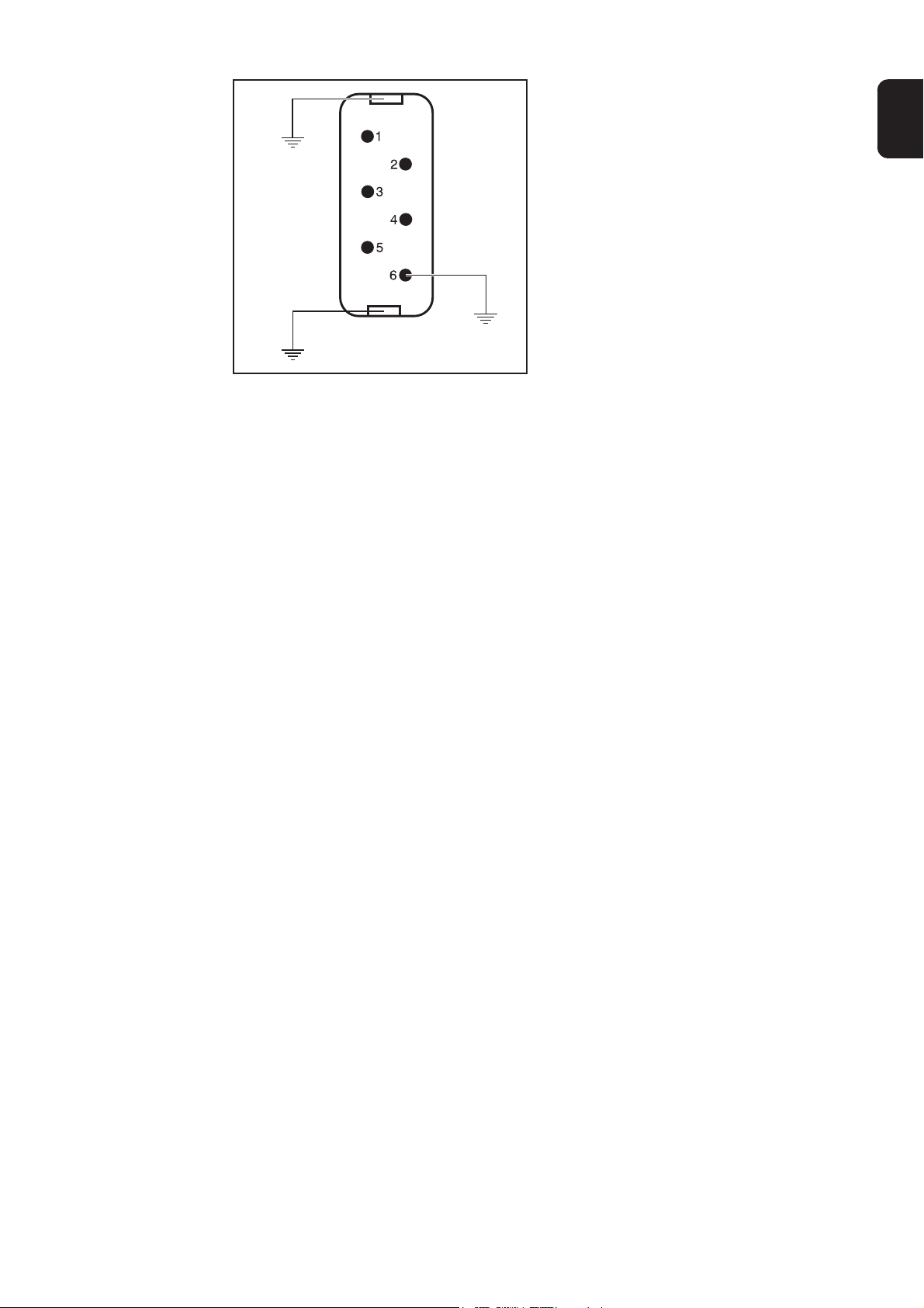
Abb.25 Netzkabel am Netzstecker des Interfaces
anschließen
1. Netzkabel am Netzstecker des
Interfaces von Master-Spannungsquelle und Slave-Spannungsquelle
anschließen:
1 ..... L1
2 ..... L2
3 ..... L3
4 ..... nicht belegt
5 ..... nicht belegt
6 ..... Masse
Wichtig! Master-Spannungsquelle und
Slave-Spannungsquelle haben jeweils eine
eigene Netzversorgung.
DE
Einstellungen im
Betrieb
Für den Betrieb des Roboterinterfaces Slave BIAS 300 Plasma an einer Spannungsquelle in Parallelkonfiguration sind keine weiteren Einstellungen erforderlich.
Die Werte für IOFFSET 1, IOFFSET 2 und Empfindlichkeit werden von der Master-Spannungsquelle vorgegeben.
13
Page 18

Steuerung externer Komponenten
Allgemeines
Steckerbelegung
von Anschluss
Arc Signals
Um eine schnelle Reaktion auf einen Lichtbogen zu gewährleisten, ist am Interface der
Anschluss Arc Signals vorhanden. Die elektrischen Signale dieser 14-poligen Amphenolbuchse kommen direkt vom Print MM_ARC der Spannungsquelle.
Pin Bezeichnung Beschreibung
A D1OUT_C Disable DPS2500 Kollektor (potentialfrei)
B D1OUT_E Disable DPS2500 Emitter (potentialfrei)
C D2OUT_C Lichtbogen-Signal Kollektor (potentialfrei)
D D2OUT_E Lichtbogen-Signal Emitter (potentialfrei)
E N.C. nicht belegt
F N.C. nicht belegt
G D1IN
1)
Disable ARC-Signalising (potentialfrei); wirkt auf die Signale
an den Pins A-D und die Signale über Lichtwellen-Leiter
H D1IN_GND
1)
Disable ARC-Signalising (potentialfrei); wirkt auf die Signale
an den Pins A-D und die Signale über Lichtwellen-Leiter
I N.C. nicht belegt
J N.C. nicht belegt
K D3IN Reserve
L D3IN_GND Reserve
M +24 V EXT +24 V extern
N GND EXT GND extern
HINWEIS! Die Spannungsversorgung zwischen Pin M und N ist nicht kurzschlussfest! Die Belastung darf maximal 50 mA betragen.
1)
Das Ausschalten der Lichtbogen-Signalisierung (Disable ARC-Signalising, Pin G H) wirkt:
- nur auf die Signale D1OUT_C, D1OUT_E, D2OUT_C und D2OUT_E (Pins A D)
- nicht auf die Lichtbogen-Signale über die Lichtwellen-Leiter
Low ... Signale an den Pins A - D sind aktiviert
High ... Signale an den Pins A - D sind deaktiviert
14
Page 19

Technische Daten
DE
Sonderspannung
Technische
Daten
Hinweis! Falsch ausgelegter Netzstecker, Netzzuleitung sowie deren Absiche-
rung kann zu schwerwiegenden Sachschäden führen. Ist das Gerät für eine
Sonderspannung ausgelegt, gelten die Technischen Daten am Leistungsschild.
Netzstecker, Netzzuleitung sowie deren Absicherung sind entsprechend auszulegen.
Versorgungsspannung 24 V
Versorgungsspannungs-Toleranz -15% / +20%
Digitale Ausgänge:
Max. Schaltspannung 30 V
Max. Schaltstrom 2 A DC
Digitale Eingänge:
Eingangsspannung 18 - 36 V
Eingangsstrom 8,3 mA (24 V)
Analoge Ausgänge:
Ausgangsspannung 0 - 10 V
Max. Ausgangsstrom 100 µA
Analoge Eingänge:
Eingangsspannung 0 - 10 V
Max. Eingangsstrom 102 µA (10 V)
Schutzart IP21
Abmessungen l/b/h 180/310/190 mm
Prüfzeichen CE
15
Page 20

Page 21

Dear Reader
Introduction
Thank you for choosing Fronius - and congratulations on your new, technically highgrade Fronius product! This instruction manual will help you get to know your new
machine. Read the manual carefully and you will soon be familiar with all the many
great features of your new Fronius product. This really is the best way to get the most
out of all the advantages that your machine has to offer.
Please also take special note of the safety rules - and observe them! In this way, you
will help to ensure more safety at your product location. And of course, if you treat your
product carefully, this definitely helps to prolong its enduring quality and reliability - things
which are both essential prerequisites for getting outstanding results.
EN
ud_fr_st_et_00493 01/2012
Page 22

Page 23

Table of contents
General remarks ........................................................................................................................................... 2
Safety ....................................................................................................................................................... 2
Device concept......................................................................................................................................... 2
Ports ......................................................................................................................................................... 2
Removing the interface slave from the BIAS 300 Plasma power source ...................................................... 3
Safety ....................................................................................................................................................... 3
Preparations ............................................................................................................................................. 3
Disconnecting cables and plugs ............................................................................................................... 4
Removing the interface slave from the BIAS 300 Plasma power source ................................................. 6
Installing the interface slave in the BIAS 300 Plasma power source............................................................. 8
Safety ....................................................................................................................................................... 8
Prerequisite for installing an interface ...................................................................................................... 8
Installing the interface slave in the BIAS 300 Plasma power source........................................................ 8
Connecting cables and plugs ................................................................................................................. 10
Finally... ...................................................................................................................................................11
Commissioning ........................................................................................................................................... 12
General remarks .................................................................................................................................... 12
Requirements for operating the power source in a parallel configuration .............................................. 12
Connecting a slave power source to the master power source.............................................................. 12
Connecting the mains cable ................................................................................................................... 12
Settings during operation ....................................................................................................................... 13
EN
Controlling external components ................................................................................................................. 14
General remarks .................................................................................................................................... 14
Plug layout of Arc Signals port ............................................................................................................... 14
Technical Data ............................................................................................................................................. 15
Special voltages ..................................................................................................................................... 15
Technical Data ........................................................................................................................................ 15
1
Page 24
General remarks
Safety
Device concept
Ports
WARNING! Operating the device incorrectly can cause serious injury and
damage. Only carry out the activities described here after you have fully read
and understood these operating instructions and the following documents:
- the power source operating instructions, particularly the chapter entitled
„Safety rules“.
- all operating instructions for the complete system
The interface slave BIAS 300 Plasma is an interface for connecting the BIAS 300 Plasma power source to a master power source in a parallel configuration.
NOTE! The interface must be connected to the power source in order for them
both to work.
(3)
(2)
(4)
(5)
(6)
(1)
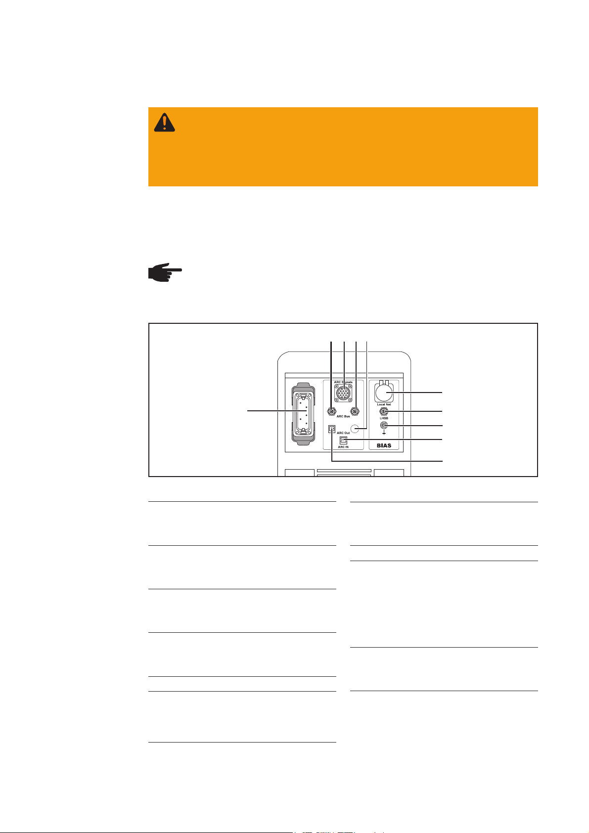
Fig. 1 Interface slave BIAS 300 Plasma, connected to the BIAS 300 Plasma power source
(1) Mains plug
6-pin Harting plug for connecting
the mains cable
(2) Arc bus port
for connecting an individual bus
system for rapid switch-off
(3) Arc Signals port
14-pin amphenol socket for
connecting the arc signals
(4) Arc bus port
for connecting an individual bus
system for rapid switch-off
(5) Blanking cover
(6) LocalNet port
standardised connection socket for
system extensions (e.g. remote
control, etc.)
(7) LHSB port
for data transmission in a parallel
configuration
(8) Ground (earth)
(9) Arc In port
Socket for fibre optic cable for transmitting the safety function signal from
an external device or an external
control (see activating/deactivating
the safety function in the power
source operating instructions)
(10) Arc Out port
Socket for connecting the arc
signals using fibre optic cables
(7)
(8)
(9)
(10)
2
Page 25
Removing the interface slave from the BIAS 300
WARNING! Work performed incorrectly can cause serious injury and damage.
The following activities must only be carried out by trained and qualified personnel! Follow the safety rules.
Plasma power source
Safety
Preparations
WARNING! An electric shock can be fatal. Before opening the power source:
- Switch off the device
- Disconnect device from the mains
- Attach a clearly legible and easy-to-understand warning sign to prevent
anyone switching it on again
- If necessary, discharge any live components (e.g. capacitors).
The housing screws provide an adequate PE conductor connection for earthing
the housing. The screws must never be replaced with different screws unless a
reliable PE conductor connection is established.
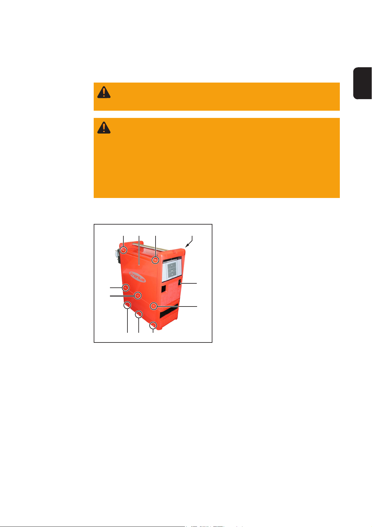
1. Turn the mains switch (4) on the
power source to the „O“ position
2. Unplug power source from the mains
3. Disconnect all cables from the power
source (current cable, arc bus cable,
LHSB cables, etc.)
4. Remove the left-hand side panel (2)
of the power source:
Undo 8 TX20 screws (1)
5. Remove the right-hand side panel (3)
of the power source:
Undo 8 TX20 screws
(1)
(1)
(1)
(3)(2) (1)
(4)
(1)
EN
(1) (1)
Fig. 2 Removing the left-hand and right-hand side
panels
(1)
3
Page 26

Preparations
(continued)
WARNING! An electric shock can be fatal. Before carrying out any work on the
power source, discharge the intermediate circuit capacitors using a resistor
rated at 1 kOhm/9 W.
(a)
12
(b)
3
4
Fig. 3 Discharging intermediate circuit capacitors
6. Discharge the intermediate circuit capacitors using a resistor rated at 1 kOhm/9 W:
- Bypass block terminals 1 and 2 for at least 10 seconds using a resistor (a)
- Bypass block terminals 3 and 4 for at least 10 seconds using a resistor (b)
Disconnecting
cables and plugs
(1)
Fig. 4 Unplugging the LHSB cable
1. Unplug LHSB cable (1)
4
Page 27

Disconnecting
cables and plugs
(continued)
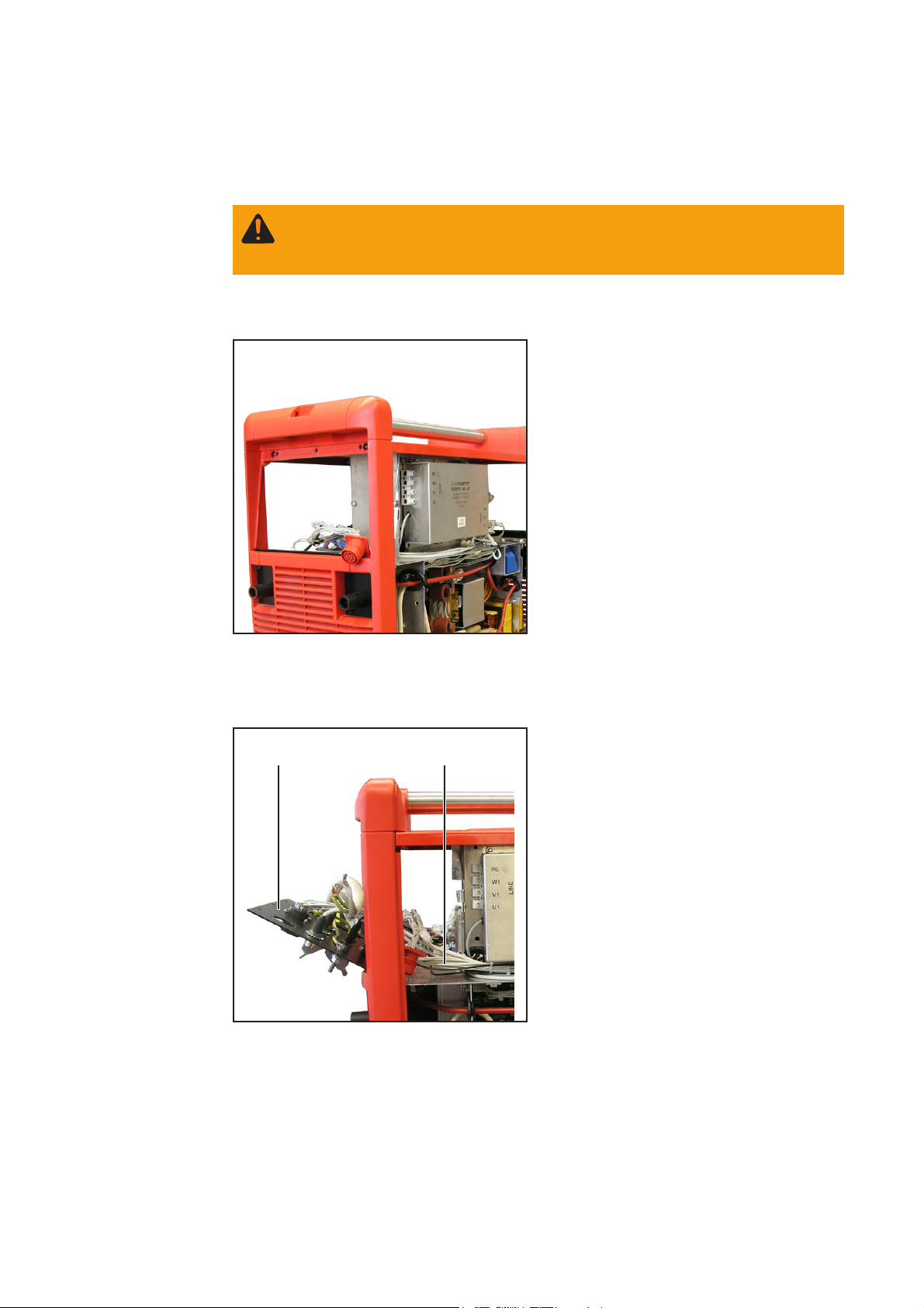
(2) (3) (4)
Fig. 5 Disconnecting the mains cable
2. Disconnect mains cable (2) from the
block terminals (3) on the mains filter (4)
EN
(5)
Fig. 6 Removing the front panel
(5)(5)
(7)
(8)
3. Undo 3 TX20 screws (5)
4. Tip front panel (6) forwards
(6)
5. Unplug fibre optic cable (7)
6. Unscrew fibre optic cable with screw
connection (8)
Fig. 7 Unplugging the fibre optic cable
5
Page 28

Disconnecting
cables and plugs
(continued)
Fig. 8 Unplugging the cable
(9) (10)
(11)(12)
7. Unplug 2-pin Molex plug X7 UEXT (9)
8. Unplug LHSB cables X12, X13 ARC
BUS (10) and (11)
9. Unplug 12-pin Molex plug X5 DIGI/O
(12)
Removing the
interface slave
from the BIAS
300 Plasma
power source
Fig. 9 Removing the plastic cover
(2) (2)(2)
(2)(3)
(1)
1. Remove plastic cover (1) from LocalNet connection
2. Undo 4 cheese-head screws (2)
3. Press LocalNet connection (3) into
inside of device
Fig. 10 Removing the LocalNet connection
6
Page 29

Removing the
interface slave
from the BIAS
300 Plasma
power source
(continued)
(4) (4) (4)
Fig. 11 Removing screws
(5) (6)
4. Undo 3 TX20 screws (4),
EN
5. ... Remove interface (5) and pull cable
harness (6) out towards you
Fig. 12 Removing the interface
Fig. 13 BIAS 300 Plasma power source without
interface
7
Page 30
Installing the interface slave in the BIAS 300 Plasma
WARNING! Work performed incorrectly can cause serious injury and damage.
The following activities must only be carried out by trained and qualified personnel! Follow the safety rules.
power source
Safety
Prerequisite for
installing an
interface
Installing the
interface slave in
the BIAS 300
Plasma power
source
Fig. 14 BIAS 300 Plasma power source without
interface
(1) (2)
Before installing an interface in the BIAS
300 Plasma power source, any existing
interface must first be removed correctly.
Important! Remove existing interface
according to the operating instructions of
the interface concerned.
1. Feed cable harness (2) through
towards the back and insert the
interface (1)
Fig. 15 Inserting the interface
8
Page 31

Installing the
interface slave in
the BIAS 300
Plasma power
source
(continued)
(3) (3) (3)
Fig. 16 Securing the interface
(4) (4)(4)
2. Fix interface in place with 3 TX20
screws (3)
EN
3. Insert LocalNet connection (5) from
(4)(5)
behind into the opening on the interface
4. Fix LocalNet connection (5) in place
with 4 cheese-head screws (2)
Fig. 17 Fitting LocalNet connection
Fig. 18 Removing the plastic cover
(6)
5. Fit plastic cover (6) to LocalNet
connection
9
Page 32

Connecting
cables and plugs
Fig. 19 Plugging in cables
(5)
(6)
(4) (3)
(2)(1)
1. Plug in 12-pin Molex plug X5 DIGI/O (1)
2. Plug in LHSB cables X12, X13 ARC
BUS (2) and (3)
3. Plug in 2-pin Molex plug X7 UEXT (4)
4. Connect fibre optic cable with screw
connection (6)
5. Plug in fibre optic cable (5)
Fig. 20 Plugging in the fibre optic cable
(7)
Fig. 21 Fitting the front panel
(7) (7)
6. Put front panel (8) in place
7. Fix front panel (8) in place using 3
TX20 screws (7)
(9)
10
Page 33

Connecting
cables and plugs
(continued)
(9) (10) (11)
Fig. 22 Connecting the mains cable
Important! Connect the yellow/green PE
conductor to the block terminal marked
„PE „ only.
8. Connect mains cable (9) to the block
terminals (10) on the mains filter (11)
EN
Finally...
(12)
Fig. 23 Plugging in the LHSB cable
(1)
9. Plug in LHSB cable (12)
(3)(2) (1)
1. Fit the right-hand side panel (3) of the
power source using 8 TX20 screws
2. Fit the left-hand side panel (2) of the
power source using 8 TX20 screws (1)
(1)
(4)
(1)
(1)
(1) (1)
Fig. 24 Fitting the left-hand and right-hand side
panels
(1)
11
Page 34

Commissioning
General remarks
Requirements for
operating the
power source in
a parallel configuration
Connecting a
slave power
source to the
master power
source
WARNING! If the device is connected to the mains supply during commissio-
ning, there is a risk of serious injury and damage. No work procedures must be
carried out unless:
- the power source mains switch is in the „O“ position,
- the device is unplugged from the mains.
- 1 master power source (power source with installed analog or Profibus interface)
+
- 1 or more slave power source(s) (power source with installed slave interface)
Important! A slave power source can only be operated in connection with a master
power source.
NOTE! When configuring power sources in parallel, ensure that the LHSB
connections and the Arc bus connections are not mixed up. If they are mixed
up, only one power source may work
1. Connect the LHSB ports on the master power source and slave power source
together using the LHSB cable provided with the robot interface slave BIAS 300
Plasma.
2. Connect the arc bus ports on the master power source and slave power source
together using the LHSB cable provided with the robot interface slave BIAS 300
Plasma.
3. Connect the control lines from the plasma process control to the master power
source interface in accordance with the interface operating instructions
Connecting the
mains cable
NOTE! Minimum palsma current cable cross-section = 16 mm²
4. Connect the plasma current cable correctly to the current connections of the master
power source and slave power source
1. Connect the mains cable to the mains
plug of the master power source and
slave power source interfaces:
1 ..... L1
2 ..... L2
3 ..... L3
4 ..... not assigned
5 ..... not assigned
6 ..... Ground (earth)
Important! Master power source and
slave power source each have their own
mains supply.
Fig. 25 Connecting the mains cable to the mains
plug on the interface
12
Page 35

Settings during
operation
When operating the robot interface slave BIAS 300 Plasma in parallel with a power
source, no other settings are necessary.
The values for IOFFSET 1, IOFFSET 2 and sensitivity are determined by the master power
source.
EN
13
Page 36

Controlling external components
General remarks
Plug layout of
Arc Signals port
The Arc Signals port is available on the interface to ensure a rapid response to an arc.
The electrical signals of this 14-pin amphenol socket come directly from the MM_ARC
PC board on the power source.
Pin Designation Description
A D1OUT_C Disable DPS2500 collector (floating)
B D1OUT_E Disable DPS2500 emitter (floating)
C D2OUT_C Arc signal collector (floating)
D D2OUT_E Arc signal emitter (floating)
E N.C. not assigned
F N.C. not assigned
G D1IN Disable ARC signalling (floating) affects the signals on pins
A-D and the signals via fibre optic cable
H D1IN_GND Disable ARC signalling (floating) affects the signals on pins
A-D and the signals via fibre optic cable
I N.C. not assigned
J N.C. not assigned
K D3IN Spare
L D3IN_GND Spare
M +24 V EXT +24 V external
N GND EXT GND external
NOTE! The power supply between pins M and N is not short circuit proof. The
maximum load is 50 mA.
1)
Switching of the arc signalling (Disable ARC signalling, pin G – H) affects:
- only the signals D1OUT_C, D1OUT_E, D2OUT_C and D2OUT_E (pins A -D)
- and not the arc signals via the fibre optic cable
Low ... signals on pins A-D are activated
High ... signals on pins A-D are deactivated
14
Page 37

Technical Data
Special voltages
Technical Data
Note: Incorrectly rated mains plugs, mains leads or fuses can lead to serious
damage. If the device is designed for a special voltage, the technical data on
the rating plate apply. The mains plug, mains lead and their fuse protection
must be rated accordingly.
Supply voltage 24 V
Supply voltage tolerance -15% / +20%
Digital outputs:
Max. switching voltage 30 V
Max. switching current 2 A DC
Digital inputs:
Input voltage 18 - 36 V
Input current 8.3 mA (24 V)
Analog outputs:
Output voltage 0 - 10 V
Max. output current 100 µA
Analog inputs:
Input voltage 0 - 10 V
Max. input current 102 µA (10 V)
Protection IP21
Dimensions l/w/h 180/310/190 mm
Marks of conformity CE
EN
15
Page 38

Page 39

FRONIUS INTERNATIONAL GMBH
Froniusplatz 1, A-4600 Wels, Austria
Tel: +43 (0)7242 241-0, Fax: +43 (0)7242 241-3940
E-Mail: sales@fronius.com
www.fronius.com
Under http://www.fronius.com/addresses you will find all addresses
www.fronius.com/addresses
of our Sales & service partners and Locations.
ud_fr_st_so_00082 012011
 Loading...