


/ Battery Charging Systems / Welding Technology / Solar Electronics
Thermo Control Fan VarioStar
Einbauanleitung
Ersatzteilliste
DEENFR
MIG/MAG Systemerweiterung
Installation Instructions
Spare Parts List
MIG/MAG system extension
Instructions d‘installation
Liste de pièces de rechange
Extension système MIG/MAG
42,0410,0947 002-05042012

Einbau der Option Temperatur gesteuerter Lüfter
DE
Sicherheit
Allgemein
Vorgangsweise
beim Einbau
Warnung! Die folgenden Arbeiten dürfen nur von geschultem Fachpersonal
durchgeführt werden!
Vor Öffnen des Gerätes:
- Netzschalter der Stromquelle in Stellung „O“ schalten
- Netzstecker der Stromquelle ziehen
Beachten Sie die Sicherheitsvorschriften in der Bedienungsanleitung Ihrer
Stromquelle.
Vorsicht! Fehlerhaft durchgeführte Arbeiten können schwerwiegende Sachschäden nach sich ziehen. Nehmen sie zum Durchführen der folgenden Arbeiten auch den Geräteschaltplan zur Hand.
Durch die Option Temperatur gesteuerter Lüfter wird der Lüfter nur eingeschaltet, wenn
die Temperatur im Inneren des Gerätes eine Lüftung erfordert. Damit sinkt der Geräuschpegel des Gerätes im Normalbetrieb und die Lebensdauer des Lüfters steigt.
1. Rechtes Seitenteil der Stromquelle
öffnen
2. Befestigungsbohrungen laut beiliegender Bohrschablone auf der Geräterückseite bohren.
3. Distanzen von außen in die Befestigungsbohrungen einsetzen
4. Print auf Distanzen aufstecken und
einrasten lassen
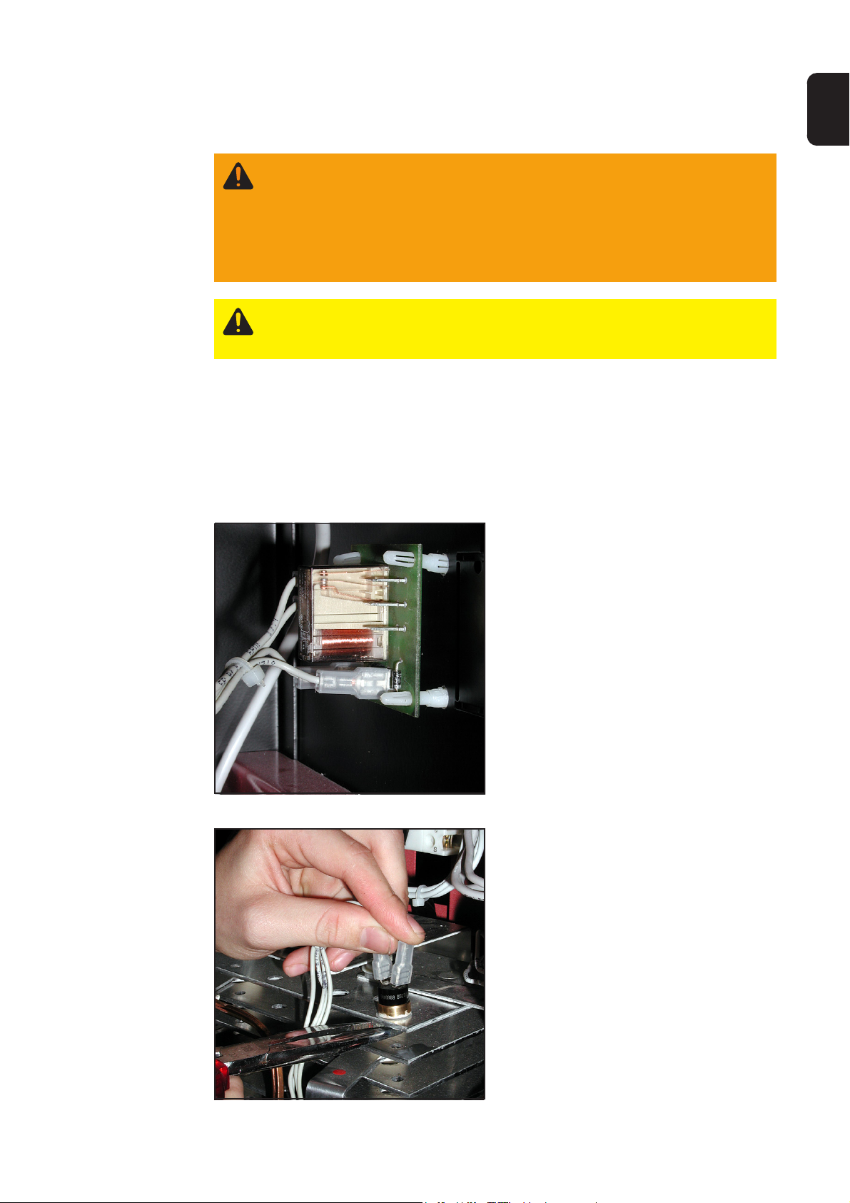
Abb.1 Print montieren
Abb.2 Temperaturfühler befestigen
5. Wärmeleitpaste auf Temperaturfühler
aufbringen
6. Temperaturfühler am Kühlkörper
aufsetzen und mit Hilfe einer Zange
die Sechskantmutter ansetzen
7. Temperaturfühler mit geeignetem
Schraubenschlüssel festschrauben
Wichtig! beim festschrauben des Temperaturfühlers darauf achten, daß das Kabel
nicht verdrillt wird
1
Vorgangsweise
beim Anschließen
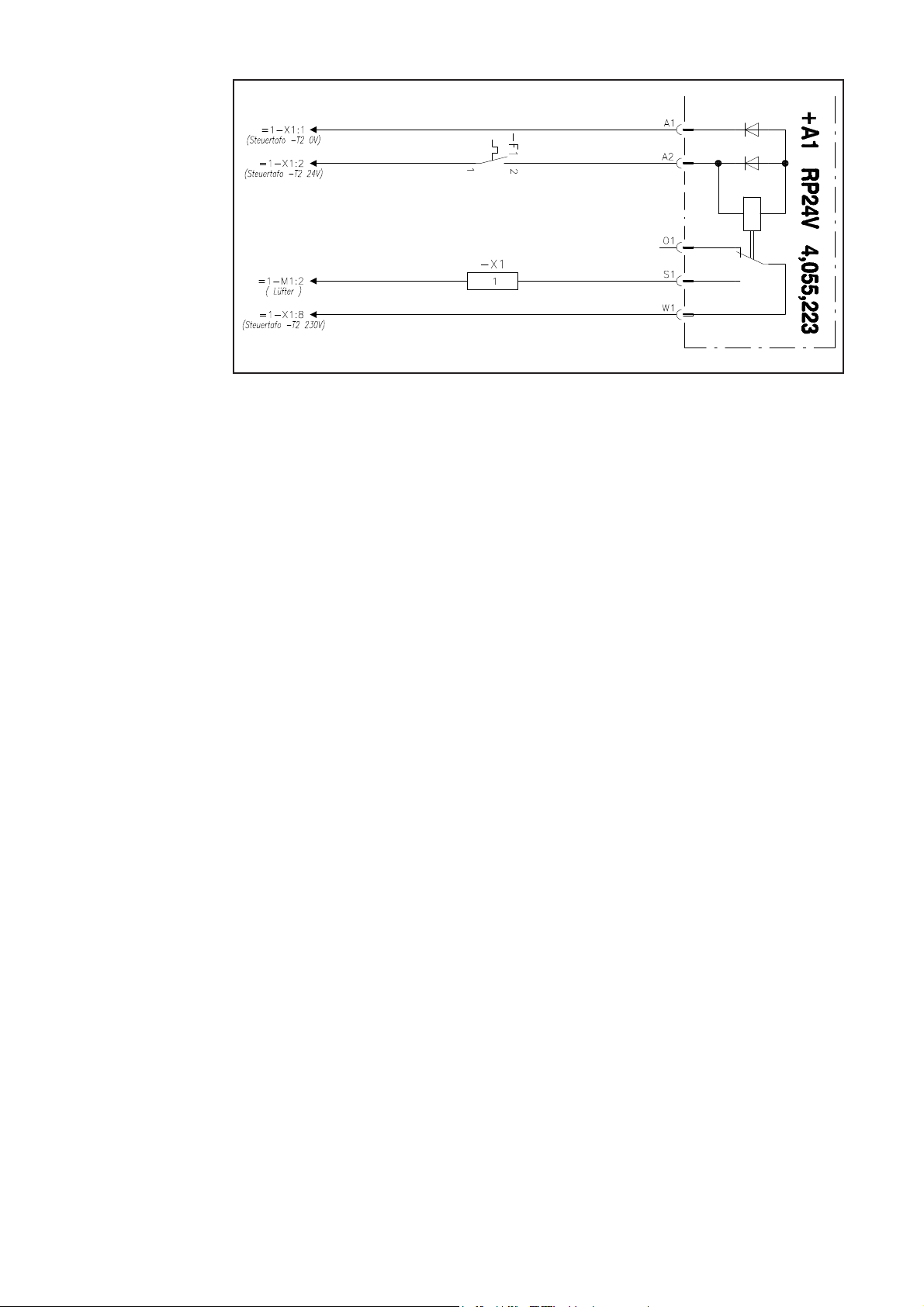
Abb.3 Schaltplan der Option Temperatur gesteuerter Lüfter
1. Die bestehende Leitung vom Steuertrafo zum Lüfter (-X1:8 zu -M1:2) auftrennen
2. Kabel der Option Temperatur gesteuerter Lüfter laut Schaltplan und Kennzeichnung
anschließen
Abschließende
Tätigkeiten
1. Einbau und Anschlüsse noch einmal kontrollieren
2. Rechtes Seitenteil der Stromquelle schließen
3. Probeschweißung durchführen
2

Installation of the temperature-controlled fan option
Safety
General
Installation
procedure
Warning! The following work must only be carried out by trained specialists.
Before opening the appliance::
- Set the mains power source switch to „O“
- Remove the power source plug from the socket
Please pay attention to the safety regulations in the instruction manual for your
power source.
Caution! Faulty work can have serious consequences. Please refer to the
switching circuit diagram when carrying out the following work.
With the temperature-controlled fan option, the fan only switches on, when the
temperature inside the appliance requires ventilation. That reduces the noise level of
the appliance under normal operating conditions and also increases the working life of
the fan.
1. Open the right-hand side of the power
source.
2. Drill mounting holes on the rear of the
appliance using the supplied template.
3. Insert spacers from the outside into
the mounting holes.
4. Fit the printed circuit board onto the
spacers and insert.
EN
Fig.1 Mount the circuit board
Fig.2 Attach the heat sensor
5. Apply heat-conducting paste to the
temperature sensor
6. Screw the temperature sensor to the
heat sink
Important! When screwing the
temperature sensor, ensure that the cable
is not twisted.
3

Wiring procedure
Fig.3 Temperature-controlled fan option circuit diagram
1. Remove the existing wire -X1:8 to -M1:2
2. Attach the temperature-controlled fan cable according to the circuit diagram and
markings
To conclude
1. Check installation and wiring again
2. Close the right-hand side of the power source
3. Carry out a test weld
4

Montage de l’option ventilateur thermocommandé
Sécurité
Généralités
Marche à suivre
pendant le montage
Avertissement! Les travaux suivants ne doivent être effectués que par des
membres du personnel ayant reçu la formation correspondante!
Avant d’ouvrir l’appareil:
- Mettre l’interrupteur principal de la source de courant en position ‘’O’’
- Débrancher la prise de la source de courant
Observez les consignes de sécurité dans le mode d’emploi de votre source de
courant.
Attention! Les travaux mal faits peuvent causer de graves dommages corporels et matériels. Consultez également le schéma des connexions pour effectuer les travaux suivants.
Grâce à l’option ventilateur thermocommandé, le ventilateur n’est mis en marche que
quand la température à l’intérieur de l’appareil rend nécessaire une aération. Ainsi, le
niveau de bruit de l’appareil baisse en service normal et la durée de vie du ventilateur
augmente.
1. Ouvrir le panneau latéral droit de la
source de courant
2. Percer des trous de fixation sur la
partie arrière de l’appareil à l’aide du
gabarit de perçage fourni
3. Placer les pièces intercalaires dans
les trous de fixation de l’extérieur
4. Ficher la plaquette à circuits imprimés
dans les pièces intercalaires et la
faire s’enclencher
FR
Fig.1 Montage de la plaquette à circuits imprimés
Fig.2 Fixation du palpeur thermométrique
5
5. Mettre de la pâte thermoconductrice
sur le palpeur thermométrique
6. Visser le palpeur thermométrique sur
le refroidisseur
Important! Veiller à ne pas vriller le câble
en vissant le palpeur thermométrique

Marche à suivre
pour le raccordement
Fig. 3 Schéma des connexions de l’option ventilateur thermocommandé
1. Défaire la ligne existante -X1:8 vers -M1:2
2. Raccorder le câble de l’option ventilateur thermocommandé suivant le schéma des
connexions et le repérage
Opérations
finales
1. Contrôler encore une fois le montage et les raccords
2. Fermer le panneau latéral droit de la source de courant
3. Faire un essai de soudage
6

Bohrschablone/Drilling pattern/Gabarit de perçage
Befestigungsbohrungen
Fitting drill holes
perçages de
fixation


4,100,406 I-kit thermo control. fan VST
4,055,223 - P24V
42,0407,0452
41,0007,0129 - 50°
41,0009,0060
Installation kit
Ersatzteilliste / Spare parts list / Listes de pièces de rechange / Lista de repuestos / Lista de pecas sobresselentes / Lista dei Ricambi
el_fr_st_so_00576 012002
1/1

FRONIUS INTERNATIONAL GMBH
Froniusplatz 1, A-4600 Wels, Austria
Tel: +43 (0)7242 241-0, Fax: +43 (0)7242 241-3940
E-Mail: sales@fronius.com
www.fronius.com
Under http://www.fronius.com/addresses you will find all addresses
www.fronius.com/addresses
of our Sales & service partners and Locations.
ud_fr_st_so_00082 012011
 Loading...