


/ Battery Charging Systems / Welding Technology / Solar Electronics
DE
EN
FR
KD-Control intern PAP / A
Internal KD Control PAP / A
KD-Control internal PAP / A
Einbauanleitung
Roboter-Option
Installation instructions
Robot option
Instructions d'installation
Option robot
42,0410,1614 004-05122012

0

Sehr geehrter Leser
Einleitung Wir danken Ihnen für Ihr entgegengebrachtes Vertrauen und gratulieren Ihnen zu Ihrem
technisch hochwertigen Fronius Produkt. Die vorliegende Anleitung hilft Ihnen, sich mit
diesem vertraut zu machen. Indem Sie die Anleitung sorgfältig lesen, lernen Sie die vielfältigen Möglichkeiten Ihres Fronius-Produktes kennen. Nur so können Sie seine Vorteile
bestmöglich nutzen.
Bitte beachten Sie auch die Sicherheitsvorschriften und sorgen Sie so für mehr Sicherheit
am Einsatzort des Produktes. Sorgfältiger Umgang mit Ihrem Produkt unterstützt dessen
langlebige Qualität und Zuverlässigkeit. Das sind wesentliche Voraussetzungen für hervorragende Ergebnisse.
DE
1

2

Allgemeines
(1)
(2)
(3)
(4)
(5)
(6)
(7)
(14)
(13)
(12)
(11)
(10)
(9)
(8)
DE
Sicherheit
ESD-Bestimmungen
WARNUNG! Ein elektrischer Schlag kann tödlich sein. Vor Öffnen des Gerätes
- Netzschalter in Stellung - O - schalten
- Gerät vom Netz trennen
- ein verständliches Warnschild gegen Wiedereinschalten anbringen
- mit Hilfe eines geeigneten Messgerätes sicherstellen, dass elektrisch geladene Bauteile (z.B. Kondensatoren) entladen sind
WARNUNG! Fehlerhaft durchgeführte Arbeiten können schwerwiegende Personen- und Sachschäden verursachen. Nachfolgend beschriebene Tätigkeiten
dürfen nur von geschultem Fachpersonal durchgeführt werden! Beachten Sie das
Kapitel „Sicherheitsvorschriften“ in der Bedienungsanleitung der Stromquelle und
der Systemkomponenten.
HINWEIS! Beachten Sie beim Umgang mit elektronischen Bauteilen und Prints
die ESD-Bestimmungen. Dazu gehören vor allem ESD-gerechte
- Verpackungen
- Arbeitsflächen
- Böden
- Sitzgelegenheiten
- Erdungsmöglichkeiten
- Handhabung
Lieferumfang
Für einen unsachgemäß behandelten elektronischen Bauteil oder Print können keine Garantie- und Gewährleistungsansprüche geltend gemacht werden.
(1) 1 Kabelzuschnitt mit 6-poligem Molexstecker
(2) 1 Kabelzuschnitt mit 4-poligem Molexstecker
(3) 1 Kabelzuschnitt mit 2-poligem Molexstecker
(4) 1 Kabelzuschnitt mit 8-poligem Molexstecker
(5) 1 Kabelzuschnitt mit 10-poligem Molexstecker
(6) 1 Kabelzuschnitt mit Anschlussbuchse
(7) 1 Print FU 60
(8) 1 Print FU 50
3

(9) 1 Print SR 41
(16)
(15)
(10) 1 Messingdistanz M5 x 10 mm
(11) 3 Messingdistanzen M5 x 30 mm
(12) 17 Kunststoff-Distanzen M4 x 30 mm
(13) 12 Kunststoff-Distanzen M4 x 10 mm
(14) 2 Schrauben T20 4 x 8 mm
Nur für den Einbau in MagicWave 4000 / 5000 und TransTig 4000 / 5000 erforderlich:
(15) 1 Adapterblech
(16) 1 Kabelverlängerung mit
6-poligem Molexstecker (Buchse /
Stecker)
Erforderliche
Werkzeuge und
Hilfsmittel
- Torx-Schraubendreher TX20
- Steckschlüssel SW 8 mm
- Seitenschneider
- Kabelbinder
4

Einbau-Set KD-Control intern PAP / A in KD-Supply
1
5
2500 einbauen
Vorbereitung Netzschalter der Stromquelle in Position - O - schalten
Netzkabel der Stromquelle vom Netz trennen
2
Stromquelle von KD-Supply 2500 trennen
3
Gehäusedeckel und Seitenteile von KD-Supply 2500 entfernen
4
Blindabdeckung bei Position „Option“ an der Rückseite entfernen
6
(1)
(1)
(1)
(1)
(1)
(1)
(3)
(2)
(1)
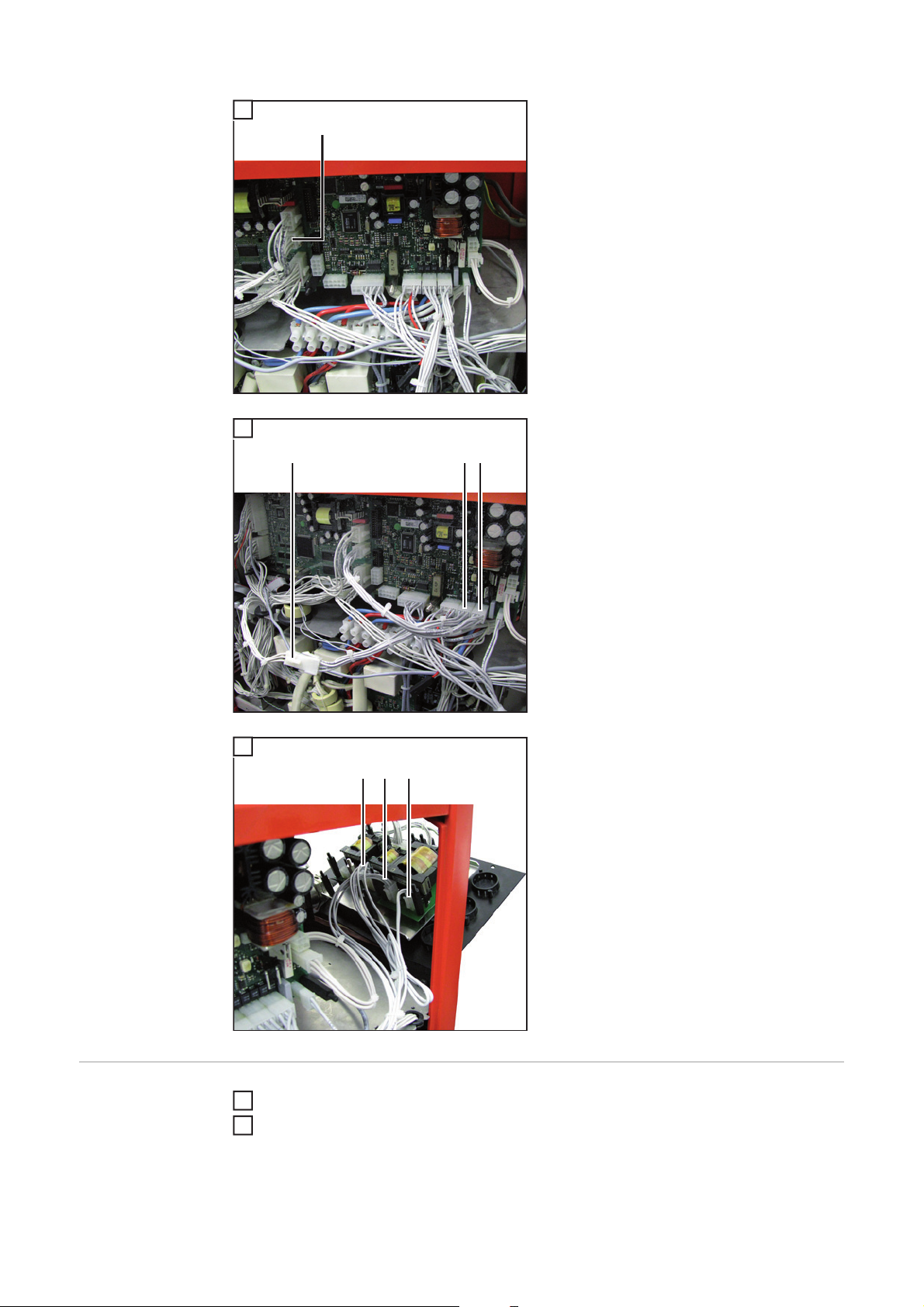
- Kunststoff-Distanzen M4 x 10 mm (1)
und Messingdistanz M5 x 10 mm (2)
gemäß Abbildung auf die vorhandenen
Gewindestifte aufschrauben
- Kabel (3) und (4) vom Print SNT3 abstecken
DE
Einbau-Set KDControll intern
PAP / A in KDSupply 2500 einbauen
1
(1) (2) (3)
(4)
(4)
- Distanzen (1) - (4) vom Print SNT3 abschrauben
- Print SNT3 zur Seite klappen
5

2
*)
- Prints vom Einbau-Set gemäß Abbildung auf die kurzen Distanzen aufsetzen
- Prints mit den Kunststoff-Distanzen M4
x 30 mm und den Messingdistanzen
(A)
(B)
M5 x 30 mm befestigen
- An den Positionen (A) - (D) jeweils eine
*)
zweite Distanz aufschrauben
*)
(C)
(D)
3
*) Messingdistanzen
- Print SNT3 auf die doppelten Distanzen aufsetzen
- Print SNT3 mit den Kunststoff-Distanzen M4 x 30 mm und einer Messingdistanz M5 x 30 mm befestigen
*) Messingdistanzen
4
- Kabelzuschnitte am Print SR 41 anstecken:
4p = 4-poliger Molexstecker
2p 6p
8p
10p
2p = 2-poliger Molexstecker
6p = 6-poliger Molexstecker
4p
8p = 8-poliger Molexstecker
10p = 10-poliger Molexstecker
6

5
- Anschlussbuchse mit dem dazugehörenden Kabelzuschnitt von innen nach
außen in die freie Öffnung an der
Rückwand einsetzen
- Anschlussbuchse mit den 2 Schrauben
T20 4 x 8 mm (5) aus dem Einbau-Set
befestigen
DE
6
(7)
(6)
7
(8)
(9)
(5)
(5)
(10)
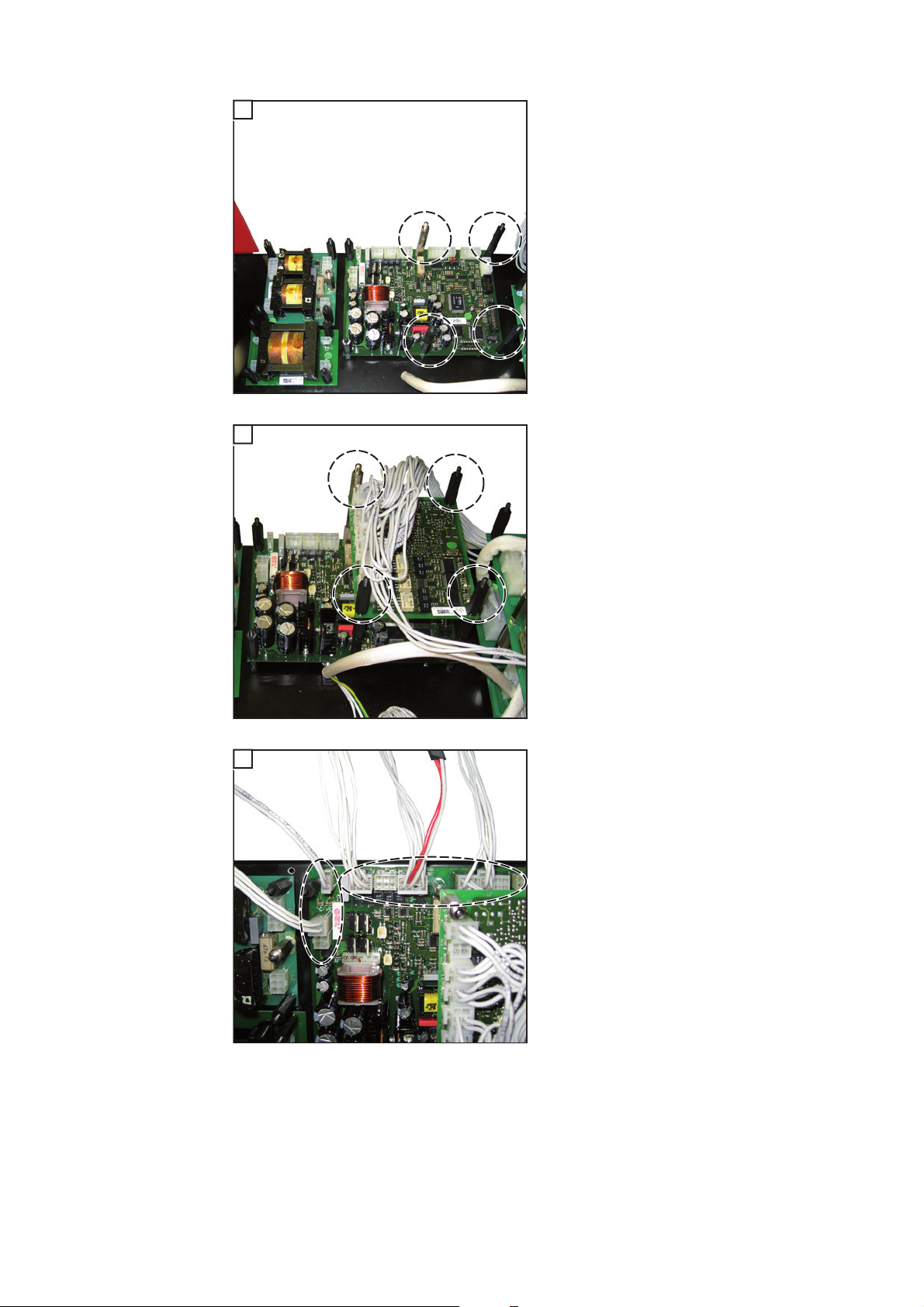
- Kabelzuschnitt mit 4-poligem Molexstecker (6) und Kabelzuschnitt mit 6poligem Molexstecker (7) am Print
SNT3 anstecken
- Kabelzuschnitt mit 2-poligem Molexstecker (8) am Print FU60 an X2 anstecken
- Kabelzuschnitt mit 4-poligem Molexstecker (9) am Print FU60 an X4 anstecken
- Kabelzuschnitt mit 10-poligem Molexstecker (10) am Print FU50 an X1 anstecken
7

8
1
(14)
(11)
(12)
(13)
Kabel vom Ausgang X9.3:
- Kabelteil mit dem 6-poligen Molexstecker (14) am Print SR41 an X6 anstecken
- Kabelteil mit dem 4-poligen Molexstecker (13) am Print SR41 an X11 anstecken
Kabel von der Anschlussbuchse:
- Kabelteil (11) und (12) am Print FU60
an X1 und X3 anstecken
WICHTIG! Kabelaufdruck beachten!
Abschließende
Tätigkeiten
Kabel mittels Kabelbinder fixieren
Seitenteile und Gehäusedeckel von KD-Supply 2500 montieren
2
Stromquelle und KD-Supply 2500 montieren
3
8

Einbau-Set KD-Control intern PAP / A in MagicWave
2
4
(3)
(4)
(3)
(3)
(3)
(3)
(3)
4000 / 5000 und TransTig 4000 / 5000 einbauen
Voraussetzung Für den Einbau des Einbau-Sets KD-Controll intern PAP / A muss das Einbau-Set KD-Mo-
torversorgung an der Stromquelle vorhanden sein.
Vorbereitung Netzschalter der Stromquelle in Position - O -schalten
1
Netzkabel der Stromquelle vom Netz trennen
Blechabdeckung an der Rückseite und rechten Seitenteil entfernen
3
Blindabdeckung bei Position „Option“ an der Blechabdeckung entfernen
5
- Anschlussbuchse (2) mit dem dazugehörenden Kabelzuschnitt von innen
nach außen in die freie Öffnung an der
Blechabdeckung einsetzen
- Anschlussbuchse mit den 2 Schrauben
T20 4 x 8 mm aus dem Einbau-Set (1)
befestigen
DE
(1)
(2)
(1)
6
- Kunststoff-Distanzen M4 x 10 mm (3)
und Messingdistanz M5 x 10 mm (4)
gemäß Abbildung auf die am Adapterblech vorhandenen Gewindestifte
aufschrauben
9

7
(3)
(3)
- Kunststoff-Distanzen M4 x 10 mm (3)
gemäß Abbildung auf die an der
Blechabdeckung vorhandenen Gewindestifte aufschrauben
Einbau-Set KDControll intern
PAP / A in MagicWave 4000 /
5000 und TransTig 4000 / 5000
einbauen
(3)
1
(1)
(2)
(3)
(1)
(1)
- Adapterblech (2) auf die Blechabdekkung aufsetzen
- Adapterblech mit Kunststoff-Distanzen
M4 x 30 mm (1) befestigen
- Print FU50 (5) auf das Adapterblech
aufsetzen
- Print FU50 (5) mit Kunststoff-Distanzen M4 x 30 mm (1) und einer Messingdistanz M5 x 30 mm (4) befestigen
- Print FU60 (3) so auf das Adapterblech
aufsetzen, dass die Anschlüsse X2
und X4 unten sind
- Print FU60 (3) mit Kunststoff-Distanzen M4 x 30 mm befestigen
(1)
(5)
(4)
(1)
2
(6)
(7)
(3)
(8)
(1)
- Kabel von der Anschlussbuchse mit 2poligem Molexstecker (8) am Print
FU60 an X1 anstecken
- Kabel mit 4-poligem Molexstecker (7)
am Print FU60 an X3 anstecken
- Kabel mit 10-poligem Molexstecker (6)
am Print FU50 an X2 anstecken
10

3
(9)
- Kabelzuschnitt mit 4-poligem Molexstecker (9) am Print NT60 anstecken
DE
4
(1)
(1)
(1)
(4)
(1)
(1)
5
10p 2p
6p
6p* 4p8p
- Print SR41 auf Print NT60 aufsetzen
- Print SR41 mit Kunststoff-Distanzen
M4 x 30 mm (1) und einer Messingdistanz M5 x 30 mm (4) befestigen
- Kabelzuschnitte am Print SR 41 anstecken:
10p = 10-poliger Molexstecker
8p = 8-poliger Molexstecker
6p* = zusätzliche Kabelverlängerung
(6-polig, Buchse /Stecker)
6p = 6-poliger Molexstecker
2p = 2-poliger Molexstecker
4p = 4-poliger Molexstecker
11
6
(10)
- Kabel mit 6-poligem Molexstecker (10)
vom Print UST2C abstecken
7
(12)
(10)
(11)
8
(13)
(15)(14)
- Kabel mit 6-poligem Molexstecker (10)
mit der zusätzlichen Kabelverlängerung (11) zusammenstecken
- Kabel mit 6-poligem Molexstecker (12)
an der freien Stelle anstecken
- Blechabdeckung mit den Prints FU50
und FU60 an der Stromquelle ansetzen
- Kabelzuschnitt mit 2-poligem Molexstecker (15) am Print FU60 an X2 anstecken
- Kabelzuschnitt mit 4-poligem Molexstecker (14) am Print FU60 an X4 anstecken
- Kabelzuschnitt mit 10-poligem Molexstecker (13) am Print FU50 an X1 anstecken
Abschließende
Tätigkeiten
12
Kabel mittels Kabelbinder fixieren
1
Blechabdeckung an der Rückseite und rechten Seitenteil montieren
2

Dear reader,
Introduction Thank you for the trust you have placed in our company and congratulations on buying this
high-quality Fronius product. These instructions will help you familiarise yourself with the
product. Reading the instructions carefully will enable you to learn about the many different
features it has to offer. This will allow you to make full use of its advantages.
Please also note the safety rules to ensure greater safety when using the product. Careful
handling of the product will repay you with years of safe and reliable operation. These are
essential prerequisites for excellent results.
EN
13

14

General
(1)
(2)
(3)
(4)
(5)
(6)
(7)
(14)
(13)
(12)
(11)
(10)
(9)
(8)
Safety
ESD guidelines
WARNING! An electric shock can be fatal. Before opening the device
- Turn the mains switch to the "O" position
- Unplug the machine from the mains
- Put up an easy-to-understand warning sign to stop anybody inadvertently
switching it back on again
- Using a suitable measuring instrument, check to make sure that electrically
charged components (e.g. capacitors) have discharged
WARNING! Work that is carried out incorrectly can cause serious injury and damage. The following activities must only be carried out by trained and qualified personnel. Read the "Safety rules" chapter in the power source and system
components operating instructions.
NOTE! Observe ESD guidelines when handling electronic components and PC
boards. This primarily applies to ESD compatible
- Packaging
- Work surfaces
-Floors
-Seating
- Earthing facilities
- Handling
EN
Scope of supply
No guarantee or warranty claims can be made in respect of any improperly handled electronic component or PC board.
(1) 1 cable cut with 6-pin Molex plug
(2) 1 cable cut with 4-pin Molex plug
(3) 1 cable cut with 2-pin Molex plug
(4) 1 cable cut with 8-pin Molex plug
(5) 1 cable cut with 10-pin Molex plug
(6) 1 cable cut with connection socket
(7) 1 FU 60 PC board
(8) 1 FU 50 PC board
15

(9) 1 SR 41 PC board
(16)
(15)
(10) 1 M5 x 10 mm brass spacer
(11) 3 M5 x 30 mm brass spacers
(12) 17 M4 x 30 mm plastic spacers
(13) 12 M4 x 10 mm plastic spacers
(14) 2 T20 4 x 8 mm screws
Only required when installing in MagicWave 4000 / 5000 and TransTig 4000 / 5000:
(15) 1 adapter plate
(16) 1 cable extension with
6-pin Molex plug (socket/plug)
Required tools
and material
- Torx screwdriver (TX20)
- Box spanner 8 mm
- Diagonal cutting pliers
- Cable ties
16

Install the KD-Control internal PAP / A installation kit
1
5
in the KD-Supply 2500
Preparations Turn the power source mains switch to the "O" position
Unplug the power source from the mains
2
Disconnect the power source from the KD-Supply 2500
3
Remove the housing cover and side panels of the KD-Supply 2500
4
Remove the blanking cover on the rear in the case of the "Option" position
6
(1)
(1)
(1)
(1)
(1)
(1)
(3)
(2)
(1)
(4)
- Screw the M4 x 10 mm plastic spacers
(1) and the M5 x 10 mm plastic spacer
(2) onto the threaded studs provided
as shown
- Disconnect cables (3) and (4) from the
SNT3 PC board
EN
Install the KDControl internal
PAP / A installation kit in the KDSupply 2500
1
(1) (2) (3)
(4)
- Unscrew spacers (1) - (4) on the SNT3
PC board
- Fold the SNT3 PC board to one side
17

2
*)
- Place the PC boards from the installation kit onto the short spacers as
shown
- Secure the PC boards using the M4 x
30 mm plastic spacers and the M5 x 30
(A)
(B)
mm brass spacers
- Screw a second spacer in place at po-
*)
sitions (A) - (D)
*)
(C)
(D)
3
*) Brass spacers
- Place the SNT3 PC board on the
doubled spacers
- Secure the SNT3 PC board using the
M4 x 30 mm plastic spacers and an M5
x 30 mm brass spacer
*) Brass spacers
4
- Plug in the cable cuts on the SR 41 PC
board:
4p = 4-pin Molex plug
2p 6p
8p
10p
2p = 2-pin Molex plug
6p = 6-pin Molex plug
4p
8p = 8-pin Molex plug
10p = 10-pin Molex plug
18

5
- Insert the connection socket and the
associated cable cut from the inside
out into the free opening on the rear
panel
- Fasten the connection socket using the
2 T20 4 x 8 mm screws (5) from the installation kit
EN
6
(7)
(6)
7
(8)
(9)
(5)
(5)
(10)
- Plug the cable cut with the 4-pin Molex
plug (6) and the cable cut with the 6-pin
Molex plug (7) onto the SNT3 PC
board
- Plug the cable cut with the 2-pin Molex
plug (8) onto X2 onto the FU60 PC
board
- Plug the cable cut with the 4-pin Molex
plug (9) into X4 on the FU60 PC board
- Plug the cable cut with the 10-pin Molex plug (10) into X1 on the FU50 PC
board
19

8
1
(14)
(11)
(12)
Finally... Bind cables together with cable ties
Fit the side panels and housing cover of the KD-Supply 2500
2
Fit the power source and KD-Supply 2500
3
(13)
Cable from output X9.3:
- Plug the cable section with the 6-pin
Molex plug (14) into X6 on the SR41
PC board
- Plug the cable section with the 4-pin
Molex plug (13) into X11 on the SR41
PC board
Cable from the connection socket:
- Plug cable sections (11) and (12) into
X1 and X3 on the FU60 PC board
IMPORTANT: Note the labelling on the cable!
20

Install the KD-Control internal PAP / A installation kit
2
4
(3)
(4)
(3)
(3)
(3)
(3)
(3)
in the MagicWave 4000 / 5000 and TransTig 4000 /
5000
Requirement To install the KD-Control internal PAP / A installation kit, the installation kit KD-Motor power
supply must be present on the power source.
EN
Preparations Turn the power source mains switch to the "O" position
1
Unplug the power source from the mains
Remove the metal cover on the rear and the right-hand side panel
3
Remove the blanking cover on the metal cover in the case of the "Option" position
5
(1)
(2)
(1)
6
- Insert the connection socket (2) and
the associated cable cut from the inside out into the free opening on the
metal cover
- Fasten the connection socket using the
2 T20 4 x 8 mm screws from the installation kit (1)
- Screw the M4 x 10 mm plastic spacers (3) and the M5 x 10 mm plastic
spacer (4) onto the threaded studs on
the adapter plate as shown
21

7
(3)
(3)
- Screw the M4 x 10 mm plastic spacers
(3) onto the threaded studs on the metal cover as shown
Install the KDControl internal
PAP / A installation kit in the
MagicWave 4000 /
5000 and TransTig 4000 / 5000
(3)
1
(1)
(2)
(3)
(1)
(1)
- Place adapter plate (2) on the metal
cover
- Fasten the adapter plate using M4 x 30
mm plastic spacers (1)
- Place the FU50 PC board (5) on the
adapter plate
- Fasten the FU50 PC board (5) using
M4 x 30 mm plastic spacers (1) and an
M5 x 30 mm brass spacer (4)
- Place the FU60 PC board (3) on the
adapter plate so that connections X2
and X4 are at the bottom
- Fasten the FU60 PC board (3) using
M4 x 30 mm plastic spacers
(1)
(5)
(4)
(1)
2
(6)
(7)
(3)
(8)
(1)
- Plug the cable from the connection socket with the 2-pin Molex plug (8) into
X1 on the FU60 PC board
- Plug the cable with the 4-pin Molex
plug (7) into X3 on the FU60 PC board
- Plug the cable with the 10-pin Molex
plug (6) into X2 on the FU50 PC board
22

3
(9)
- Plug the cable cut with the 4-pin Molex
plug (9) onto the NT60 PC board
EN
4
(1)
(1)
(1)
(4)
(1)
(1)
5
10p 2p
6p
6p* 4p8p
- Place the SR41 PC board on the NT60
PC board
- Fasten the SR41 PC board using M4 x
30 mm plastic spacers (1) and an M5 x
30 mm brass spacer (4)
- Plug in the cable cuts on the SR 41 PC
board:
10p = 10-pin Molex plug
8p = 8-pin Molex plug
6p* = addition cable extension (6-pin,
socket/plug)
6p = 6-pin Molex plug
2p = 2-pin Molex plug
4p = 4-pin Molex plug
23

6
(10)
- Disconnect the cable with the 6-pin
Molex plug (10) from the UST2C PC
board
7
(12)
(10)
(11)
8
(13)
(15)(14)
- Connect the cable with the 6-pin Molex
plug (10) to the additional cable extension (11)
- Connect the cable with the 6-pin Molex
plug (12) to the free location
- Place the metal cover with the FU50
and FU60 PC boards on the power
source
- Plug the cable cut with the 2-pin Molex
plug (15) into X2 on the FU60 PC
board
- Plug the cable cut with the 4-pin Molex
plug (14) into X4 on the FU60 PC
board
- Plug the cable cut with the 10-pin Molex plug (13) into X1 on the FU50 PC
board
Finally... Bind cables together with cable ties
24
1
Fit the metal cover to the rear and the right-hand side panel
2

Cher lecteur
Introduction Nous vous remercions de la confiance que vous nous témoignez et nous vous félicitons
d'avoir acquis ce produit Fronius de haute qualité technique. Les présentes Instructions de
service doivent vous permettre de vous familiariser avec ce produit. Par une lecture attentive, vous apprendrez à connaître les diverses possibilités de votre produit Fronius. C'est
ainsi seulement que vous pourrez en exploiter au mieux tous les avantages.
Respectez les consignes de sécurité et veillez par ce biais à garantir davantage de sécurité sur le lieu d'utilisation du produit. Une manipulation appropriée de ce produit garantit
sa qualité et sa fiabilité à long terme. Ces deux critères sont des conditions essentielles
pour un résultat optimal.
FR
25

26

Généralités
Sécurité
Directives relatives aux décharges
électrostatiques
AVERTISSEMENT ! Un choc électrique peut être mortel. Avant d'ouvrir l'appareil
- commuter l’interrupteur du secteur en position - O -
- débrancher l'appareil du secteur
- apposer un panneau d'avertissement compréhensible afin de prévenir toute
remise en marche
- s'assurer, à l'aide d'un appareil de mesure approprié, que les composants à
charge électrique (condensateurs par ex.) sont déchargés
AVERTISSEMENT ! Les erreurs en cours d'opération peuvent entraîner des
dommages corporels et matériels graves. Les opérations décrites ci-après doivent être effectuées exclusivement par du personnel qualifié et formé ! Respecter
les prescriptions du chapitre « Consignes de sécurité » figurant dans les Instructions de service de la source de courant et des composants du système.
REMARQUE! Respectez les directives relatives aux décharges électrostatiques
lors de la manipulation des composants électroniques et circuits imprimés. Les
éléments suivants doivent être adaptés aux décharges électrostatiques :
- Emballages
- Plans de travail
-Sols
-Sièges
- Possibilités de mise à la terre
- Manipulation
FR
Livraison
La garantie ne couvre pas les composants électroniques et circuits imprimés utilisés de
manière non conforme aux instructions.
(4)
(5)
(2)
(1)
(1) 1 section de câble avec fiche Molex 6 pôles
(2) 1 section de câble avec fiche Molex 4 pôles
(3) 1 section de câble avec fiche Molex 2 pôles
(4) 1 section de câble avec fiche Molex 8 pôles
(5) 1 section de câble avec fiche Molex 10 pôles
(6) 1 section de câble avec connecteur
(3)
(6)
(10)
(11)
(12)
(13)
(14)
(7)
(8)
(9)
27

(7) 1 circuit imprimé FU 60
(8) 1 circuit imprimé FU 50
(9) 1 circuit imprimé SR 41
(10) 1 pièce d'écartement en laiton M5 x 10 mm
(11) 3 pièces d'écartement en laiton M5 x 30 mm
(12) 17 pièces d'écartement en plastique M4 x 30 mm
(13) 12 pièces d'écartement en plastique M4 x 10 mm
(14) 2 vis T20 4 x 8 mm
Nécessaire uniquement pour le montage dans MagicWave 4000 / 5000 et TransTig 4000
/ 5000 :
(15) 1 plaque d'adaptation
(16) 1 rallonge de câble avec
(15)
(16)
fiche Molex 6 pôles (connecteur/prise)
Outils et accessoires requis
- Tournevis Torx TX20
- Clé à douille SW 8 mm
- Pince coupante de côté
- Attache-câbles
28

Installer le kit d'installation KD-Control intern PAP /
1
5
A dans l'alimentation KD-Supply 2500
Préparation Placer l'interrupteur principal de la source de courant en position - O -
Débrancher du réseau le câble d'alimentation de la source de courant
2
Déconnecter la source de courant de l'alimentation KD Supply 2500
3
Retirer le couvercle de boîtier et les parties latérales de l'alimentation KD Supply 2500
4
Sur la face arrière, retirer la fausse prise de la position « Option »
FR
Installer le kit
d'installation KDControll intern
PAP / A dans l'alimentation KDSupply 2500
6
(1)
(1)
(1)
1
(1) (2) (3)
(1)
(2)
(1)
(1)
(1)
(3)
(4)
(4)
- Visser les pièces d'écartement en plastique M4 x 10 mm (1) et la pièce d'écartement en laiton M5 x 10 mm (2) sur les
tiges filetées existantes, conformément à l'illustration
- Déconnecter les câbles (3) et (4) du
circuit imprimé SNT3
- Dévisser les pièces d'écartement (1) et
(4) du circuit imprimé SNT3
- Replier le circuit imprimé SNT3 sur le
côté
29
2
*)
- Placer les circuits imprimés du lit d'installation sur les pièces d'écartement
courtes, conformément à l'illustration
- Fixer les circuits imprimés avec les pièces d'écartement en plastique M4 x
(A)
(B)
30 mm et les pièces d'écartement en
laiton M5 x 30 mm
*)
- Visser une seconde pièce d'écartement sur les positions (A) - (D)
*)
*) Pièces d'écartement en laiton
(C)
3
(D)
- Placer le circuit imprimé SNT3 sur les
doubles pièces d'écartement
- Fixer le circuit imprimé SNT3 avec les
pièces d'écartement en plastique M4 x
30 mm et une pièce d'écartement en
laiton M5 x 30 mm
*) Pièces d'écartement en laiton
4
- Connecter les sections de câbles sur le
circuit imprimé SR 41 :
4p = fiche Molex 4 pôles
2p 6p
8p
10p
2p = fiche Molex 2 pôles
6p = fiche Molex 6 pôles
4p
8p = fiche Molex 8 pôles
10p = fiche Molex 10 pôles
30

5
- Insérer le connecteur avec les sections
de câble correspondantes, de l'intérieur vers l'extérieur dans l'ouverture libre sur la paroi arrière
- Fixer le connecteur avec les 2 vis T20
4 x 8 mm (5) du kit d'installation
FR
6
(7)
(6)
7
(8)
(9)
(5)
(5)
(10)
- Connecter la section de câble avec
fiche Molex 4 pôles (6) et la section de
câble avec fiche Molex 6 pôles (7) sur
le circuit imprimé SNT3
- Connecter la section de câble avec
fiche Molex 2 pôles (8) sur le circuit imprimé FU60 en X2
- Connecter la section de câble avec
fiche Molex 4 pôles (9) sur le circuit imprimé FU60 en X4
- Connecter la section de câble avec
fiche Molex 10 pôles (10) sur le circuit
imprimé FU50 en X1
31

8
1
(14)
(11)
(12)
Étapes finales Fixer les câbles au moyen des attache-câbles
Remonter le couvercle de boîtier et les parties latérales de l'alimentation KD Supply
2
2500
Remonter la source de courant et l'alimentation KD Supply 2500
3
(13)
Câble de la sortie X9.3 :
- Connecter la partie de câble avec la
- Connecter la partie de câble avec la
Câble du connecteur :
- Connecter les parties de câble (11) et
IMPORTANT ! Respecter les inscriptions
figurant sur les câbles !
fiche Molex 6 pôles (14) sur le circuit
imprimé SR41 en X6
fiche Molex 4 pôles (13) sur le circuit
imprimé SR41 en X11
(12) sur le circuit imprimé FU60 en X1
et X3
32

Monter le kit d'installation KD-Control intern PAP / A
2
4
(3)
(4)
(3)
(3)
(3)
(3)
(3)
dans MagicWave 4000 / 5000 et TransTig 4000 / 5000
Condition préalable
Préparation Placer l'interrupteur principal de la source de courant en position - O -
Pour le montage du kit d'installation KD-Controll intern PAP / A, le kit d'installation KD Alimentation moteur doit être installé sur la source de courant.
1
Débrancher du réseau le câble d'alimentation de la source de courant
Retirer la tôle de protection sur la face arrière et la partie latérale droite
3
Sur la tôle de protection, retirer la fausse prise de la position « Option »
5
(1)
(2)
- Insérer le connecteur (2) avec les sections de câble correspondantes, de
l'intérieur vers l'extérieur dans l'ouverture libre sur la tôle de protection
- Fixer le connecteur avec les 2 vis T20
4 x 8 mm du kit d'installation (1)
FR
(1)
6
- Visser les pièces d'écartement en
plastique M4 x 10 mm (3) et la pièce
d'écartement en laiton M5 x 10 mm
(4) sur la plaque d'adaptation, conformément à l'illustration
33

7
(3)
(3)
- Visser les pièces d'écartement en plastique M4 x 10 mm (3) sur les tiges filetées de la tôle de protection,
conformément à l'illustration
Monter le kit
d'installation KDControll intern
PAP / A dans MagicWave 4000 /
5000 et TransTig
4000 / 5000
(3)
1
(1)
(2)
(3)
(1)
(1)
- Placer la plaque d'adaptation (2) sur la
tôle de protection
- Fixer la plaque d'adaptation avec les
pièces d'écartement en plastique M4 x
30 mm (1)
- Placer le circuit imprimé FU50 (5) sur
la plaque d'adaptation
- Fixer le circuit imprimé FU50 (5) avec
les pièces d'écartement en plastique
M4 x 30 mm (1) et une pièce d'écartement en laiton M5 x 30 mm (4)
- Placer le circuit imprimé FU60 (3) sur
la plaque d'adaptation de manière à ce
que les connexions X2 et X4 soient
placées en-dessous
(1)
(5)
(4)
(1)
(3)
(1)
- Fixer le circuit imprimé FU60 (3) avec
pièces d'écartement en plastique M4 x
30 mm
2
(6)
(7)
(8)
- Connecter le câble du connecteur avec
fiche Molex 2 pôles (8) sur le circuit imprimé FU60 en X1
- Connecter le câble avec fiche Molex 4
pôles (7) sur le circuit imprimé FU60 en
X3
- Connecter le câble avec fiche Molex
10 pôles (6) sur le circuit imprimé FU50
en X2
34

3
(9)
- Connecter la section de câble avec
fiche Molex 4 pôles (9) sur le circuit imprimé FU60
FR
4
(1)
(1)
(1)
(4)
(1)
(1)
5
10p 2p
6p
6p* 4p8p
- Placer le circuit imprimé SR41 sur le
circuit imprimé NT60
- Fixer le circuit imprimé SR41 avec les
pièces d'écartement en plastique M4 x
30 mm (1) et une pièce d'écartement
en laiton M5 x 30 mm (4)
- Connecter les sections de câbles sur le
circuit imprimé SR 41 :
10p = fiche Molex 10 pôles
8p = fiche Molex 8 pôles
6p* = rallonge de câble supplémentaire (6 pôles, connecteur / fiche)
6p = fiche Molex 6 pôles
2p = fiche Molex 2 pôles
4p = fiche Molex 4 pôles
35

6
(10)
- Déconnecter le câble avec fiche Molex
6 pôles (10) du circuit imprimé UST2C
7
(12)
(10)
(11)
8
(13)
(15)(14)
- Brancher le câble avec fiche Molex 6
pôles (10) à la rallonge de câble supplémentaire (11)
- Brancher le câble avec fiche Molex 6
pôles (12) à l'emplacement disponible
- Remettre en place sur la source de
courant la tôle de protection avec les
circuits imprimés FU50 et FU60
- Connecter la section de câble avec
fiche Molex 2 pôles (15) sur le circuit
imprimé FU60 en X2
- Connecter la section de câble avec
fiche Molex 4 pôles (14) sur le circuit
imprimé FU60 en X4
- Connecter la section de câble avec
fiche Molex 10 pôles (13) sur le circuit
imprimé FU50 en X1
Étapes finales Fixer les câbles au moyen des attache-câbles
36
1
Monter la tôle de protection sur la face arrière et la partie latérale droite
2

Appendix

Circuit diagram: Internal KD Control PAP / A
38

39

FRONIUS INTERNATIONAL GMBH
Froniusplatz 1, A-4600 Wels, Austria
Tel: +43 (0)7242 241-0, Fax: +43 (0)7242 241-3940
Under http://www.fronius.com/addresses you will find all addresses
of our Sales & service partners and Locations
E-Mail: sales@fronius.com
www.fronius.com
www.fronius.com/addresses
 Loading...