


/ Battery Charging Systems / Welding Technology / Solar Electronics
External Stop - Inching enable
Bedienungsanleitung
MIG/MAG-Systemerweiterung
DEENFR
Operating Instructions
MIG/MAG system extension
Instructions de service
Extension système MIG/MAG
42,0410,1335 002-04052012


Sehr geehrter Leser
DE
Einleitung
Wir danken Ihnen für Ihr entgegengebrachtes Vertrauen und gratulieren Ihnen zu Ihrem
technisch hochwertigen Fronius Produkt. Die vorliegende Anleitung hilft Ihnen, sich mit
diesem vertraut zu machen. Indem Sie die Anleitung sorgfältig lesen, lernen Sie die
vielfältigen Möglichkeiten Ihres Fronius-Produktes kennen. Nur so können Sie seine
Vorteile bestmöglich nutzen.
Bitte beachten Sie auch die Sicherheitsvorschriften und sorgen Sie so für mehr Sicherheit am Einsatzort des Produktes. Sorgfältiger Umgang mit Ihrem Produkt unterstützt
dessen langlebige Qualität und Zuverlässigkeit. Das sind wesentliche Voraussetzungen
für hervorragende Ergebnisse.
ud_fr_st_et_00491 01/2012


Einbau-Set „External Stop - Inching enable“
Allgemeines Die werkseitig eingebaute Option „External Stop - Inching enable“ ist eine Sicherheitsein-
richtung für Stromquellen. „External Stop - Inching enable“ gewährleistet ein sicheres
Abschalten der Stromquelle innerhalb einer Sekunde mit definiertem Schweißende. Die
Spannungsversorgung des Drahtvorschub-Motors bleibt dabei aufrecht, sodass das
Ausführen der Funktion Drahteinfädeln weiterhin möglich ist.
DE
Systemvoraussetzungen
Funktionsprinzip - 6-polige Buchse der Option „External Stop - Inching enable“: für den Schweißbetrieb
Für die einwandfreie Funktion der Option „External Stop - Inching enable“ muss die
Stromquelle über die Firmware BETA UST V3.31.11 oder höher verfügen.
muss an Pin B und E eine Spannung von +24 V SELV (Safety Extra Low Voltage)
anliegen.
- Fällt die Spannung weg, werden unabhängig von der Software die Ansteuersignale
zu den Leistungstransistoren des Primär-Leistungsteils über Relais unterbrochen.
„External Stop - Inching enable“ stoppt den laufenden Schweißbetrieb. Die Schweißspannung wird abgeschaltet. Die Spannungsversorgung des Drahtvorschub-Motors
bleibt aufrecht.
- Die Stromquelle gibt über das Roboter-Interface den Fehler-Code „E078“ aus. Am
Display der Stromquelle wird „E-Stop“ angezeigt.
- Bei diesem Schweißstopp ist ein über die Software definierter Draht-Rückbrand
gewährleistet.
- Zusätzlich wird bei ausgelöstem „E-Stop“ durch das Schließen eines Kontaktes
zwischen Pin C und F ein Signal generiert. Dieses Signal kann über eine Kontrollspannung mit max. 24 V SELV und max. 10 mA z.B. über einer Robotersteuerung
ausgewertet werden.
- Die Kommunikation über Roboter-Interface oder Bussystem bleibt aufrecht.
- Bei automatisierten Anwendungen muss der Fehler „E078“ von der Robotersteuerung über das Signal „Source Error Reset“ quittiert werden.
Bei manuellen Anwendungen entfällt das Quittieren des Fehlers „E078“. Die Stromquelle ist nach erneutem Anlegen der Spannung von +24 V SELV wieder schweißbereit.
- Zum Fortsetzen des Schweißbetriebes muss das Startsignal (Schweißen Ein,
welding start) erneut angelegt werden.
Anschlussbelegung
6-polige Buchse der Option „External Stop - Inching
enable“, z.B. an der Rückseite der Stromquelle oder
an der Uni-Box
1
Pin Belegung
A +24 V (LocalNet)
B Signaleingang +24 V SELV
C E-Stop aktiv +
(max. +24 V SELV, max. 10 mA)
D GND (LocalNet)
E Signaleingang GND SELV
F E-Stop aktiv -
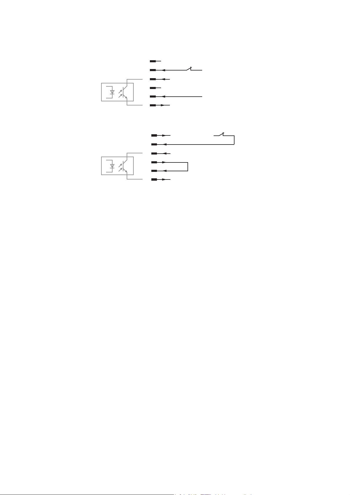
Stecker konfigurieren
Den mitgelieferten Stecker entsprechend folgender Möglichkeiten konfigurieren:
a) Spannung +24 V SELV vorhanden (externe Spannungsversorgung):
A
B
C
E-Stop aktiv +
+24 V SELV
D
E
F
E-Stop aktiv -
GND
b) Spannung +24 V SELV nicht vorhanden (interne Spannungsversorgung):
A
+24 V LocalNet
B
C
D
E-Stop aktiv +
GND
E
F
E-Stop aktiv -
2

Dear Reader
Introduction
Thank you for choosing Fronius - and congratulations on your new, technically highgrade Fronius product! This instruction manual will help you get to know your new
machine. Read the manual carefully and you will soon be familiar with all the many
great features of your new Fronius product. This really is the best way to get the most
out of all the advantages that your machine has to offer.
Please also take special note of the safety rules - and observe them! In this way, you
will help to ensure more safety at your product location. And of course, if you treat your
product carefully, this definitely helps to prolong its enduring quality and reliability - things
which are both essential prerequisites for getting outstanding results.
EN
ud_fr_st_et_00493 01/2012


„External Stop - Inching enable“ installation set
General remarks The factory-installed „External Stop - Inching enable“ option is a safety feature for power
sources. „External Stop - Inching enable“ ensures that the power source switches off
safely within one second, with the end of welding clearly defined. The wirefeeder motor
power supply remains unaffected, so that the feeder inching function can still be used.
EN
System requirements
Functional principle
The power source must have BETA UST firmware V3.31.11 or higher for the „External
Stop - Inching enable“ option to function properly.
- 6-pin socket for the „External Stop - Inching enable“ option: for welding mode, the
voltage on pins B and E must be +24 V SELV (Safety Extra Low Voltage).
- If the voltage drops out, the control signals to the power transistors on the primary
power modules are interrupted via a relay, regardless of the software. „External Stop
- Inching enable“ stops the present welding mode. The welding voltage is switched
off. The power supply to the wirefeeder motor remains unaffected.
- The power source outputs error code „E078“ via the robot interface. „E-Stop“ appears on the power source display.
- When welding stops, software-defined wire burnback is ensured.
- In addition, a signal is generated if an emergency stop is triggered when a contact
between pin C and F is closed. This signal can be evaluated using a control voltage
of maximum 24 V SELV and a maximum of 10 mA, e.g. via a robot control.
- Communication via the robot interface or the bus system remains unaffected.
- In automated applications, error „E078“ must be reset by the robot control using the
„Source Error Reset“ signal.
In manual applications, error „E078“ does not need to be reset. Once the +24 V
SELV is restored, the power source can start welding again.
- To continue welding, the start signal (welding start) must be displayed.
Pin assignments
6-pin socket for „External Stop - Inching enable“
option, e.g. on the rear of the power source or on
the Uni-Box
Pin Assignment
A +24 V (LocalNet)
B Signal input +24 V SELV
C E-Stop active +
(max. +24 V SELV, max. 10 mA)
D GND (LocalNet)
E Signal input GND SELV
F E-Stop active -
1
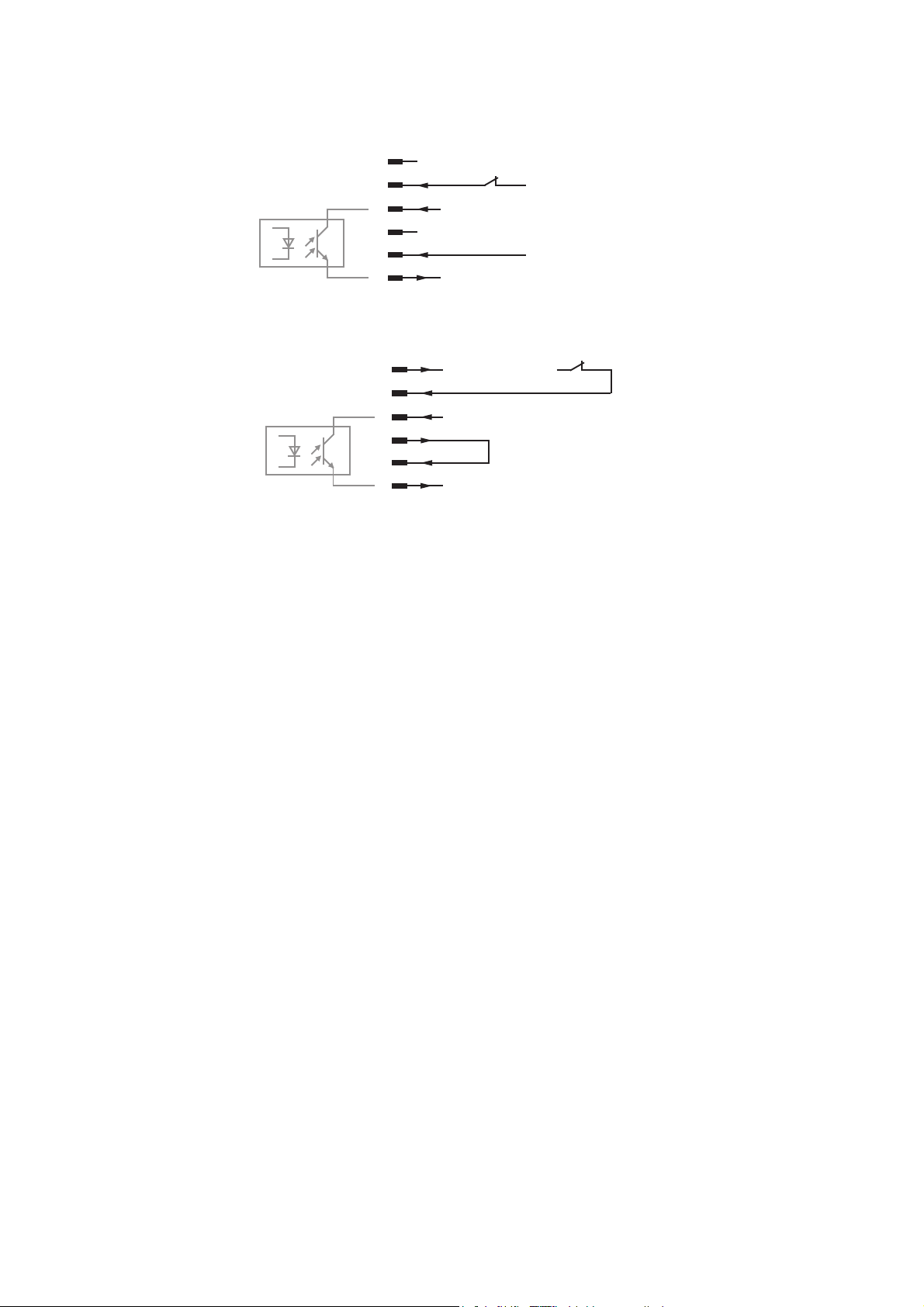
Plug wiring
Wire the supplied plug according to one of the following:
a) +24 V SELV available (external power supply):
A
B
C
E-Stop active +
+24 V SELV
D
E
F
E-Stop active -
GND
b) +24 V SELV not available (internal power supply):
A
+24 V LocalNet
B
C
D
E-Stop active +
GND
E
F
E-Stop active -
2

Cher lecteur
Introduction
Nous vous remercions de votre confiance et vous félicitons d’avoir acheté un produit de
qualité supérieure de Fronius. Les instructions suivantes vous aideront à vous familiariser avec le produit. En lisant attentivement les instructions de service suivantes, vous
découvrirez les multiples possibilités de votre produit Fronius. C’est la seule manière
d’exploiter ses avantages de manière optimale.
Prière d’observer également les consignes de sécurité pour garantir une sécurité accrue
lors de l’utilisation du produit. Une utilisation soigneuse du produit contribue à sa longévité et sa fiabilité. Ce sont des conditions essentielles pour obtenir d’excellents résultats.
FR
ud_fr_st_et_00500 01/2012


Kit d’installation „External Stop - Inching enable“
Généralités L’option montée en usine „External Stop - Inching enable“ est un dispositif de sécurité
pour les sources de courant. „External Stop - Inching enable“ garantit un arrêt en toute
sécurité de la source de courant dans un délai d’une seconde, avec une fin de soudage
déterminée. L’alimentation électrique du moteur du dévidoir est ainsi maintenue, afin de
pouvoir poursuivre l’exécution de la fonction Introduction du fil.
Configuration du
système
Pour un fonctionnement optimal de l’option „External Stop - Inching enable“, la source de
courant doit être équipée du logiciel BETA UST V3.31.11 ou version supérieure.
FR
Principe de
fonctionnement
- Connecteur 6 pôles de l’option „External Stop - Inching enable“ : pour le mode
Soudage, une tension de +24 V SELV (Safety Extra Low Voltage) doit apparaître au
niveau des broches B et E.
- Si la tension chute, les signaux de commande vers les transistors de puissance de
l’étage de puissance primaire sont interrompus par les relais, indépendamment du
logiciel. „External Stop - Inching enable“ arrête le mode Soudage en cours. La
tension de soudage est mise hors service. L’alimentation électrique du moteur du
dévidoir est maintenue.
- La source de courant émet le code d’erreur „E078“ par le biais de l’interface robot.
„E-Stop“ apparaît sur l’affichage de la source de courant.
- Cet arrêt du soudage garantit une brûlure retour du fil définie par le logiciel.
- En outre, lorsque „E-Stop“ est activé, un signal est généré par la fermeture d’un
contact entre les broches C et F. Ce signal peut être analysé par une tension de
contrôle de 24 V SELV max. et 10 mA max., par exemple au moyen d’une commande robot.
- La communication par interface robot ou système de bus est maintenue.
- Dans les applications automatisées, l’erreur „E078“ de la commande robot doit être
validée par le signal „Source Error Reset“.
Dans les applications manuelles, la validation de l’erreur „E078“ n’est pas nécessaire. La source de courant est à nouveau prête à souder après le rétablissement
de la tension de +24 V SELV.
- Pour poursuivre le mode Soudage, le signal de démarrage (Soudage déclenché,
Welding Start) doit à nouveau être émis.
Schéma de
connexion
Connecteur 6 pôles de l’option „External Stop Inching enable“, par exemple à l’arrière de la source
de courant ou sur l’Uni-Box
1
Broche Affectation
A +24 V (LocalNet)
B Entrée signal +24 V SELV
C E-Stop actif +
(+24 V SELV max., 10 mA max.)
D GND (LocalNet)
E Entrée signal GND SELV
F E-Stop actif -

Configurer la
prise fournie
Configurer la prise fournie en fonction des possibilités suivantes :
a) tension +24 V SELV disponible (alimentation électrique externe) :
A
B
C
E-Stop actif +
+24 V SELV
D
E
F
E-Stop actif -
GND
b) tension +24 V SELV non disponible (alimentation électrique interne) :
A
+24 V LocalNet
B
C
D
E-Stop actif +
GND
E
F
E-Stop actif -
2

Schaltplan / Circuit diagram / Schéma des connexions

FRONIUS INTERNATIONAL GMBH
Froniusplatz 1, A-4600 Wels, Austria
Tel: +43 (0)7242 241-0, Fax: +43 (0)7242 241-3940
E-Mail: sales@fronius.com
www.fronius.com
Under http://www.fronius.com/addresses you will find all addresses
www.fronius.com/addresses
of our Sales & service partners and Locations.
ud_fr_st_so_00082 012011
 Loading...