

Operating
Instructions
GEN24 & Tauro Country Setup Menu
Operating Instructions
EN
42,0426,0413,EN 009-09012023

Contents
General 4
Country setup 4
Access code 4
Adjusting parameters with the Fronius Solar.start app 5
Adjusting parameters with the browser 5
Country setup 7
Country setup selection 9
Country setup selection 9
General 10
Startup and Reconnection 10
Ramp Rates 11
Safety 14
Unintentional Islanding Detection 14
Isolation monitoring 14
DC Arc Fault Protection 16
RCMU 18
DC Shutdown Communication 19
Interface Protection 20
Voltage 20
Frequency 23
DC Injection 27
Grid Support Functions 29
Voltage Fault Ride Through (VFRT) 29
Active Power 41
Reactive Power 63
EN
3
General
Country setup The "Country Setup" menu area is intended exclusively for installers/service
technicians from authorised specialist companies. The access code must be requested from the national/international Fronius point of contact using an application form.
CAUTION!
Risk due to unauthorised access.
Incorrectly set parameters can negatively influence the public grid and/or the inverter feeding energy into the grid, and lead to a loss of conformity with the
standard.
The parameters may only be adjusted by installers/service technicians from
▶
authorised specialist companies.
Do not give the access code to third parties and/or unauthorised persons.
▶
WARNING!
Danger due to unauthorised error analyses and repair work.
This can result in serious injury and damage to property.
Fault analyses and repair work on the photovoltaic system may only be car-
▶
ried out by installers/service technicians from authorized specialist companies in accordance with national standards and guidelines.
The selected country setup for the respective country contains preset parameters according to the nationally applicable standards and requirements. Depending on local grid conditions and the specifications of the energy provider, adjustments to the selected country setup may be necessary.
CAUTION!
Risk due to incorrectly set parameters.
Incorrectly set parameters can negatively influence the public grid and/or cause
faults and failures on the inverter, and lead to the loss of standard conformity.
The parameters may only be adjusted by installers/service technicians from
▶
authorised specialist companies.
The parameters may only be adjusted if the energy provider permits or re-
▶
quires this.
Only adjust the parameters taking into account the nationally applicable
▶
standards and/or directives and the specifications of the energy provider.
Access code The "Country setup" menu area is intended exclusively for installers/service tech-
nicians from authorised specialist companies. The access code must be requested from the national/international Fronius point of contact using an application
form.
4
CAUTION!
1 2
open access point
Setup your PV system in a few minutes.
START INSTALLATION
LOGIN
Log in with your Fronius credentials (email adress
& password) in order to get the most out of the
PV System. Installing a new product does not
require a Login.
Imprint & Contact Terms & ConditionsData Privacy
Fronius Solar.start
open access point
1
FRONIUS_PILOTxxx
Secured
Password:
12345678
2
192.168.250.181
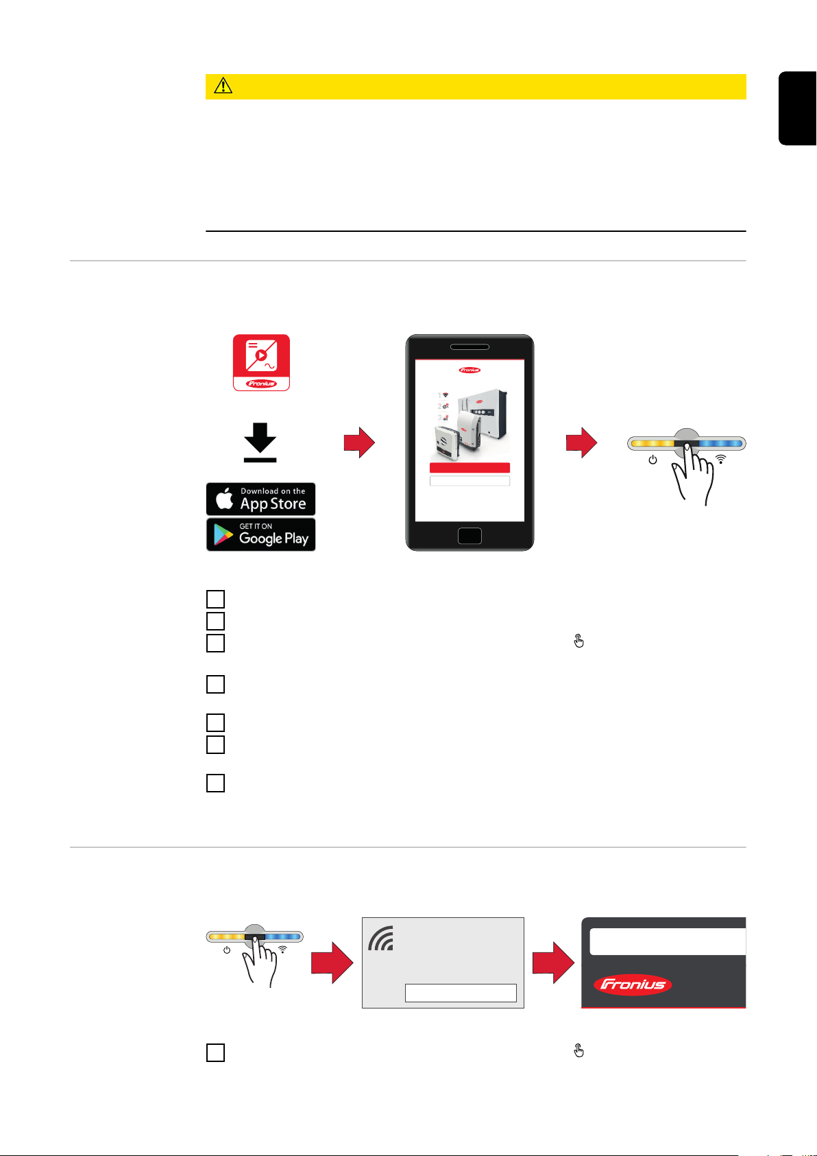
Adjusting parameters with the
Fronius Solar.start app
Risk due to unauthorised access.
Incorrectly set parameters can negatively influence the public grid and/or the inverter feeding energy into the grid, and lead to a loss of conformity with the
standard.
The parameters may only be adjusted by installers/service technicians from
▶
authorised specialist companies.
Do not give the access code to third parties and/or unauthorised persons.
▶
The "Fronius Solar.start" app is needed for registration. Depending on the end
device, the app is available on the respective platform.
EN
Adjusting parameters with the
browser
Start the installation in the app.
1
Select the product to which the connection should be established.
2
3
Open the access point by touching the sensor once → Communication LED:
flashes blue.
Select the "Technician" user in the "User menu" and enter and confirm the
4
password for the "Technician" user.
Call up the "Safety and grid regulations" → "Country setup" menu area.
5
Enter the requested access code (see chapter Access code on page 4) in the
6
input field "Access code country setup" and click the button "Activate".
Adjust the parameters in the individual menu areas taking into account the
7
nationally applicable standards and/or the specifications of the energy provider.
WLAN:
1
Open the access point by touching the sensor once → Communication LED:
flashes blue.
5
Establish the connection to the inverter in the network settings (the inverter
169.254.0.180
21
open access point
2
is displayed with the name "FRONIUS_PILOT" and the serial number of the
device).
Password: enter 12345678 and confirm.
3
IMPORTANT!
To enter the password on a Windows 10 operating system, the link "Connect
using a security key instead" must first be activated to establish a connection
with the password: 12345678.
In the browser address bar, enter and confirm the IP address
4
192.168.250.181.
Select the "Technician" user in the "User menu" and enter and confirm the
5
password for the "Technician" user.
Call up the "Safety and grid regulations" → "Country setup" menu area.
6
Enter the requested access code (see chapter Access code on page 4) in the
7
input field "Access code country setup" and click the button "Activate".
Adjust the parameters in the individual menu areas taking into account the
8
nationally applicable standards and/or the specifications of the grid operator.
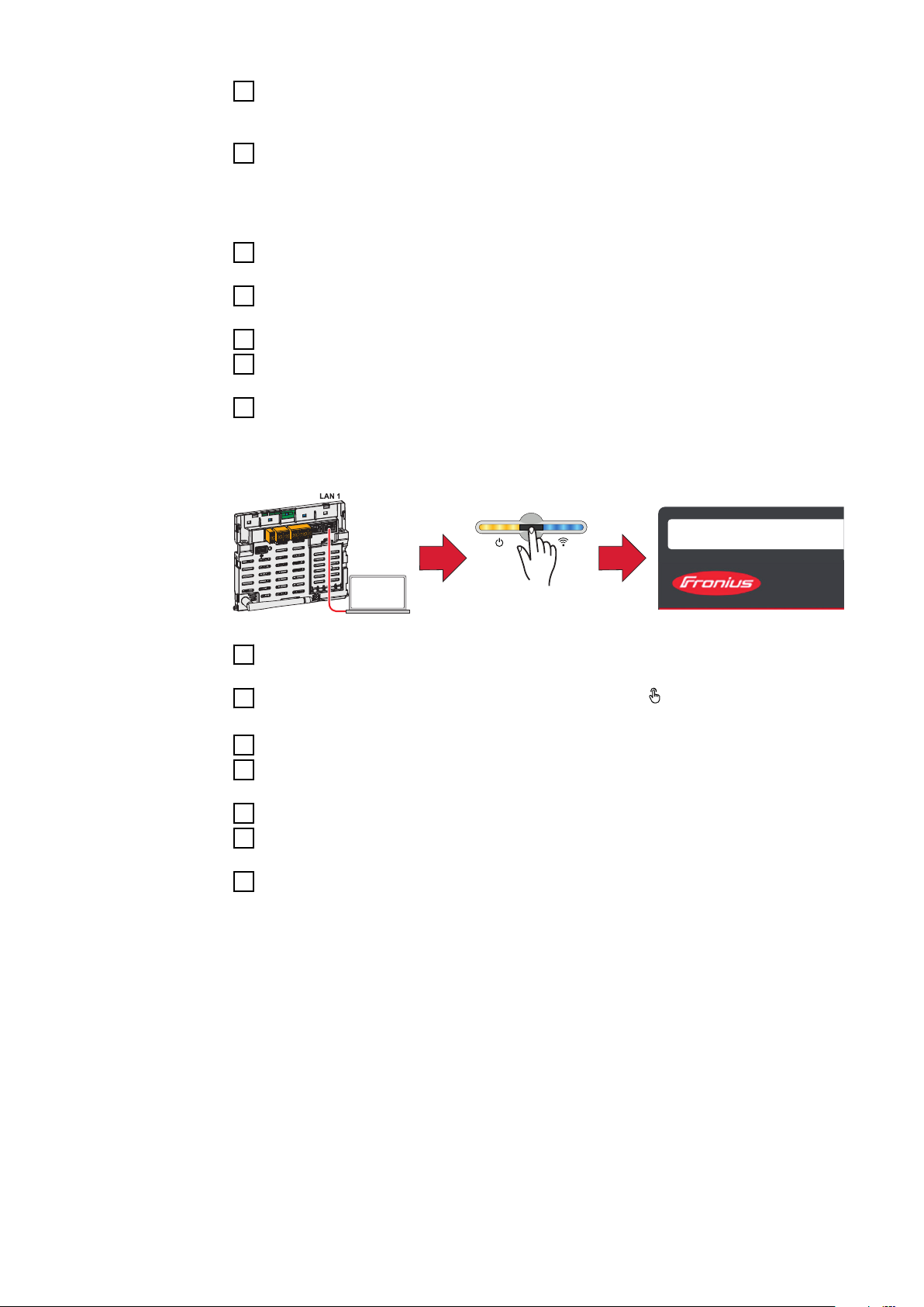
Ethernet:
Establish a connection to the inverter (LAN1) with a network cable (CAT5
1
STP or higher).
2
Open the access point by touching the sensor once → Communication LED:
flashes blue.
In the browser address bar, enter and confirm IP address 169.254.0.180.
3
Select the "Technician" user in the "User menu" and enter and confirm the
4
password for the "Technician" user.
Call up the "Safety and grid regulations" → "Country setup" menu area.
5
Enter the requested access code (see chapter Access code on page 4) in the
6
input field "Access code country setup" and click the button "Activate".
Adjust the parameters in the individual menu areas taking into account the
7
nationally applicable standards and/or the specifications of the grid operator.
6

Country setup
7

8
Country setup selection
EN
Country setup
selection
Predefined setups can be selected in the "Country setup selection" menu. The
selected country setup for the respective country contains preset parameters
according to the nationally applicable standards and requirements. Depending
on local grid conditions and the specifications of the energy provider, adjustments to the selected country setup may be necessary.
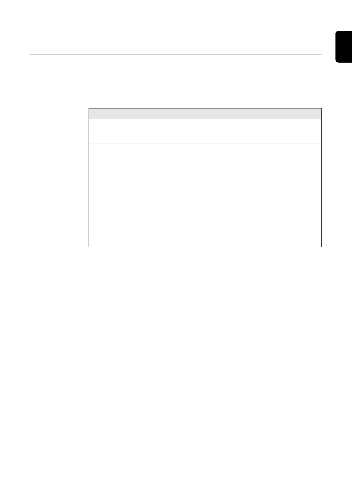
Parameter Description
"Country / Region" Selecting the respective country or region limits/
displays the available country setups for the inverter.
"Country setup" Displays the available setups per country/region.
A setup is a device configuration predefined by
Fronius. The selection of the country setup must be
made in consideration of the applicable standards
or in coordination with the grid operator.
"Rated Frequency (Hz)" The rated frequency is predetermined by the coun-
try setup selection. Changing this parameter affects
the stable operation of the inverter and is therefore
only permitted in consultation with Fronius.
"Rated Voltage (V)" The rated voltage is predetermined by the choice of
the country setup. Changing this parameter affects
the stable operation of the inverter and is therefore
only permitted in consultation with Fronius.
9

General
Startup and Reconnection
These parameters can be used to set the grid monitoring times before the inverter is switched on.
For the set time, both the mains voltage and the grid frequency must be within
the permissible range before connection is allowed.
The permissible range for the mains voltage is defined in the menu area
-
"Grid and system protection" → "Voltage" → "Startup and reconnection"
(see chapter Voltage).
The permissible range for the grid frequency is defined in the menu area
-
"Grid and system protection " → " Frequency " → " Startup and reconnection" (see chapter Frequency).
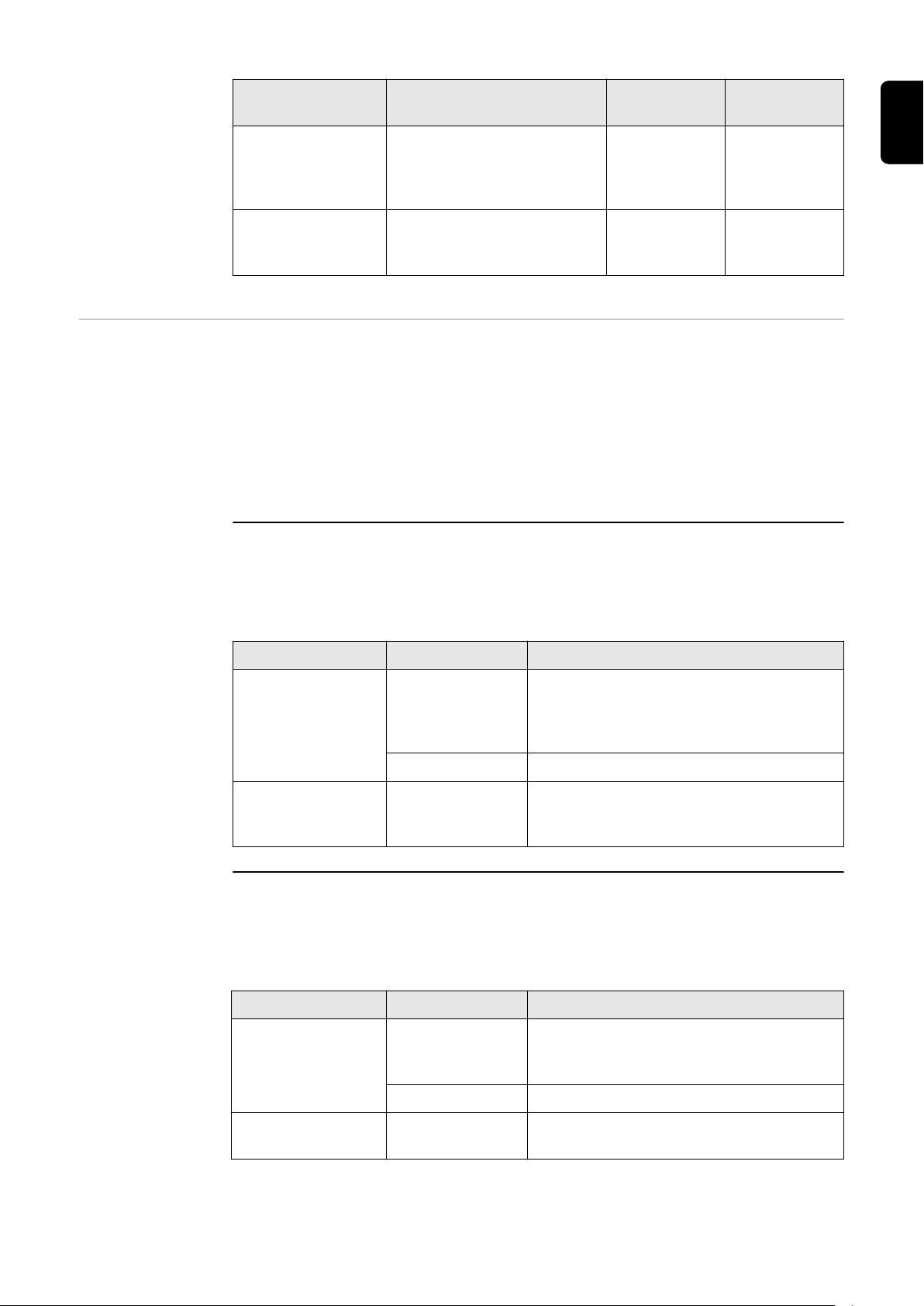
Parameter Range of values Description
"Grid Monitoring
Time Startup"
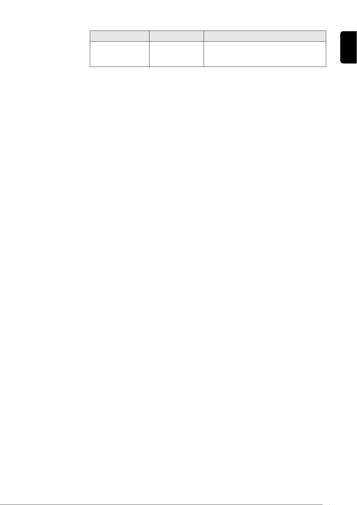
Parameter Range of values Description
"Grid Monitoring
Time Reconnection"
1 - 900 [s] Grid monitoring time before the invert-
er is switched on during a normal startup process in seconds (e.g. at sunrise).
1 - 900 [s] Grid monitoring time before the invert-
er is switched back on after a grid fault
(see table "Grid faults") in seconds
(e.g. if a fault occurs in the AC grid during the day which causes the inverter to
shut down).
The following errors are defined by the inverter as grid errors for this functionality:
Name Description "StateCode"
name
"Overvoltage" Mains voltage exceeds an
overvoltage limit ("Inner,
Middle, or Outer Limit
Overvoltage").
"Undervoltage" Mains voltage falls below
an undervoltage limit ("In-
ner, Middle or Outer Limit
Undervoltage").
"Overfrequency" Grid frequency exceeds an
overfrequency limit ("In-
ner, Outer or Alternative
Limit Overfrequency").
"Underfrequency"
Grid frequency falls below
an underfrequency limit
("Inner, Outer or Alternat-
ive Limit Underfrequency").
"AC voltage
too high"
"AC voltage
too low"
"AC frequency too
high"
"AC frequency too
low"
"StateCode"
number
1114
1119
1035
1037
10
"Fast Overvoltage Disconnect"
Triggering of the fast surge
protection (> 135%).
"Grid voltage
too high (fast
overvoltage
cut-out)"
1115, 1116
Name Description "StateCode"
name
"Long Time Average Overvoltage
Limit"
Mains voltage exceeds the
long-term overvoltage limit ("Long Time Average
Limit").
"Long-term
mains
voltage limit
exceeded"
"StateCode"
number
1117
EN
"Unintentional Islanding Detection."
Ramp Rates Ramp rates limit the maximum rate of change of effective power in special situ-
ations. Rising ramps ("Ramp-Up") limit the increase in effective power at the inverter AC output. Falling ramps ("Ramp-Down") limit the reduction of effective
power at the AC output of the inverter.
Note that the lowest rate of change is applied if there are multiple rate of change
specifications. An "Irradiation Ramp" can thus be rendered ineffective by, for ex-
ample, a lower "Startup Ramp" or another function affecting the rate of change
(e. g., P(U) or P(F)).
"Ramp-Up at Startup and Reconnection"
When connecting the inverter, the maximum rate of change of the effective
power can be limited by a rising ramp with a defined gradient. As soon as the effective power increase is influenced due to the available PV power or another
control, the ramp is terminated.
Parameter Range of values Description
Unintentional islanding
was detected.
"Islanding
detected"
1004
"Ramp-Up at
Startup and Reconnection"
"Ramp-Up at
Startup and Reconnection Rate."
"Ramp-Up/Down Irradiation"
The "Irradiation Ramp" is a permanent limitation of the rate of change for the ef-
fective power. If the PV power changes rapidly due to passing clouds, the rate of
change of the inverter output power is limited with the "Ramp-Up Irradiation
Rate" or the "Ramp-Down Irradiation Rate".
Parameter Range of values Description
"Ramp-Up Irradiation"
"Ramp-Up Irradiation Rate"
On The effective power is limited at the
"Startup" or a "Reconnection" with a
rate of change of "Ramp-Up at Startup
and Reconnection Rate".
Off The function is deactivated.
0.001 ‑ 100
[%/s]
On The effective power increase is limited
Off The function is deactivated.
0.001 - 200
[%/s]
Permitted rate of change of the effective power at "Startup" or "Reconnec-
tion".
with a rate of change of "Ramp-Up Ir-
radiation Rate".
Permitted rate of change during power
increase.
11

Parameter Range of values Description
"Ramp-Down Irradiation"
Note: This func-
tion only has an
effect on inverters with storage.
"Ramp-Down Irradiation Rate"
Example: Effective power limitation by "Irradiation-Ramp-Up/Down", which was
caused by a change in the available PV power.
On The effective power reduction is limited
with a rate of change of "Ramp-Down
Irradiation Rate".
Off The function is deactivated.
0.001 - 200
[%/s]
Permitted rate of change of effective
power.
"Ramp-Up/Down Communication"
This is a limitation of the effective power rate of change when changing external
specifications for effective power. These can be, for example, power limitations
via I/Os or Modbus commands. If smaller rates of change are specified via Modbus command, these are applied. Larger rates are limited by the parameter
"Ramp-Up Communication Rate" or "Ramp-Down Communication Rate".
Parameter Range of values Description
"Ramp-Up Communication"
"Ramp-Up Communication Rate"
"Ramp-Down
Communication"
On The limitation of the rate of change
(corresponding to "Ramp-Up Commu-
nication Rate") in case of effective
power increase due to an external specification is activated.
Off The function is deactivated.
0.001 ‑ 100
[%/s]
On The limitation of the rate of change
Off The function is deactivated.
Permitted rate of change during power
increase.
(corresponding to "Ramp-Down Com-
munication Rate") in the event of ef-
fective power reduction due to an external specification is activated.
12
Parameter Range of values Description
"Ramp-Down
Communication
Rate"
0.001 ‑ 100
[%/s]
Permitted rate of change for power reduction.
EN
13

Safety
Unintentional Islanding Detection
Unintentional islanding
In the event of a grid failure or disconnection of a small part of the grid from the
higher-level utility grid, it is possible under special conditions for local loads and
inverters to establish unintentional islanding. If the generation and load (of both
active and reactive power) are balanced, the AC voltage and frequency can remain within the allowable limits. In this case, the inverter (without additional islanding detection) will continue feeding energy into the grid, will not automatically shut down, and will supply power to the local loads. This is an unwanted condition. To prevent these situations, active or passive islanding detection methods
can be used.
Active islanding detection
The inverter's active islanding detection function detects unwanted islanding
situations, the inverter stops feeding energy into the grid and disconnects from
the AC grid at all poles.
The detection process is carried out using a grid frequency shift method (Active
Frequency Drift): In the event of short-term grid frequency changes, the inverter
feeds in an alternating current with a changed frequency (frequency shift). In the
event of an interruption to the grid, the AC voltage will also change its frequency.
There is a co-feedback effect, whereby the frequency is shifted so much that it
exceeds or falls below the permissible limits. This causes the inverter to stop
feeding energy into the grid.
In the case of three-phase inverters, the method is also able to detect islanding
on any individual phases. This function is an active islanding detection method,
since the inverter specifically changes its feed-in behaviour during the detection
process.
Standard
Parameter Range of values
"Unintentional
Islanding Detection."
"Quality Factor" 0.1 ‑ 10.0 1.0 The higher this value, the
In contrast, there are passive methods that detect islanding based only on the
measurement of AC network variables. This group includes, for example, "Rate of
Change of Frequency (RoCoF) Protection".
On Active islanding detection
Off Off Active islanding detection
value Description
is activated.
is deactivated.
stronger/more aggressive
the frequency shift of the
island detection.
Higher values therefore
result in shorter island detection times. However,
values that are too high
can also have a negative
effect on the voltage quality.
Isolation monitoring
14
Isolation monitoring ("Iso Monitoring")
The inverter performs an isolation measurement at the DC terminals of the PV
generator before each connection (at least once a day). Isolation monitoring

must be activated for both the isolation warning and the isolation error.
Isolation Warning
The measured value of the isolation monitoring is used for an isolation warning.
Status code 1083 is displayed if the measured value falls below an adjustable
limit value.
Isolation Error
The measured value of the isolation monitoring is also used for isolation error
monitoring. If the measured isolation value is below the limit value "Isolation Er-
ror Threshold", feeding energy into the grid is prevented and status code 1082 is
displayed.
IMPORTANT!
For the "Isolation Monitoring" function, the parameters in the two menu sections described must be configured accordingly.
The parameters below in the menu item "Safety and grid regulations" →
1
"Country setup" → "Safety" → "Isolation monitoring" are used to configure
the parameters for the isolation measurement:
Parameter Range of values Description
"Iso Monitoring
Mode"
On The function is activated.
Off The function is deactivated.
Off (with Warning)
Isolation monitoring is deactivated and
status code 1189 is permanently displayed on the user interface of the inverter.
EN
"Isolation Error
Threshold"
0.1 ‑ 10 MOhm If the measured isolation value is lower
than this value, feeding energy into the
grid is prevented (if isolation monitoring
is activated) and status code 1182 is
displayed on the user interface of the
inverter.
The parameters below in the menu item "Device configuration" → "Inverter"
2
→ "Iso warning" are used to configure the parameters for the isolation warning:
Parameter Range of values Description
"Iso Warning"
On The isolation warning is activated.
If the isolation warning threshold is undershot, a warning occurs but not a
shutdown.
Off The function is deactivated.
"Isolation measurement mode"
Precise Isolation monitoring is performed with
the highest accuracy and the measured
insulation resistance is displayed on the
user interface of the inverter.
Quick Isolation monitoring is performed with
lower accuracy, which shortens the duration of the isolation measurement and
the isolation value is not displayed.
15
Parameter Range of values Description
DC Arc Fault
Protection
"Isolation Warning Threshold"
These parameters can be used to set the behaviour of the arc detection at the
DC terminals of the inverter. The DC Arc Fault Protection function protects
against arc faults and contact faults. Any faults that occur in the current and
voltage curve are constantly evaluated and the current circuit is switched off if a
contact fault is detected. This prevents overheating on defective contacts and
possible fires.
Parameter
"Arc Fault Detection (AFD)"
0.1 ‑ 10 MOhm If this value is undershot, status code
1183 is displayed on the user interface
of the inverter.
Range of values Description
For activating and deactivating the arc
fault detection. The parameters "Arc logging" and "Automatic reconnects" are
only considered with activated "Arc Fault
Detection (AFD)".
Off Arcs are not detected.
Off (with
Warning)
Arcs are not detected and status code
1184 is permanently displayed on the user
interface of the inverter.
"Arc-Fault Circuit Interrupter
(CI)"
On The arc detection is active.
Describes the behaviour in the event of a
detected arc and simultaneously activates/deactivates the integrated self-test.
Off The detection of an arc does not cause the
inverter to shut down and is not displayed
on the user interface of the inverter.
Off (with
Warning)
On If an arc is detected, the inverter inter-
The detection of an arc does not cause the
inverter to shut down. The status code
1185 is permanently displayed on the user
interface of the inverter.
rupts feeding energy into the grid and the
status code 1006 is displayed on the user
interface of the inverter.
Depending on the configuration of the
parameter "Automatic Reconnects", the
inverter will attempt to restart feeding energy into the grid after 5 minutes. Furthermore, an integrated self-test is active,
which is executed at regular intervals. If
this fails, the inverter stops feeding energy
into the grid and status code 1009 is displayed.
16

Parameter
"Automatic Reconnects"
Range of values Description
If more arcs have been detected within 24
hours than are defined in "Automatic Re-
connects", the inverter will not make any
further attempt to start feeding energy into the grid. The status code 1006 is displayed on the user interface of the inverter after each detection and must be acknowledged manually.
Unlimited The 24 hour counter is deactivated. The in-
verter restarts feeding energy into the grid
5 minutes after each arc detected.
EN
0 - No Reconnection
1 ‑ 4 After a shutdown by an arc, 1, 2, 3 or 4 at-
"Arc Logging" Enables or disables the recording of arc
Off Arc signatures are not recorded.
On Arc signatures are recorded, uploaded to
After an arc has been detected, no further
attempt is made to start feeding energy
into the grid and status code 1173 is displayed on the user interface of the inverter.
tempts are made within 24 hours to restart feeding energy into the grid. After
this number of attempts, no further attempt is made to start feeding energy into
the grid and status code 1173 is displayed
on the user interface of the inverter.
signatures. The data is uploaded to the
cloud and used to continuously improve
the interference immunity and fault tolerance of arc detection.
the cloud, and used to continuously improve the interference immunity and fault
tolerance of arc detection.
"Automatic Signal Recording"
Activates or deactivates recording of the
inverter's signal characteristics to continuously improve arc detection.
Off Recording is deactivated.
On Recording is activated. With a probability
in accordance with the "Recording Prob-
ability" parameter, data is recorded and
uploaded to the cloud every 10 minutes.
17
Parameter
Range of values Description
"Recording
Probability"
RCMU The inverter is equipped with a universal current-sensitive residual current monit-
oring unit (RCMU) in accordance with IEC 62109-2. This unit monitors residual
currents from the PV module to the AC output of the inverter and disconnects
the inverter from the grid in the event of unauthorised residual current.
Parameter
If "Automatic Signal Recording (ASR)" is
activated, the frequency for a recording
can be set here.
0 No signal characteristics are recorded.
0.0 ‑ 1.0 Every 10 minutes, data is uploaded to the
cloud with a frequency in accordance with
the "Recording Probability".
Example:
With a setting value of 0.1, data is uploaded on average every 100 minutes.
1 Data is recorded every 10 minutes.
Range of values Description
"RCMU" Off The protective function is deactivated.
Off (with
Warning)
On The protective function is activated.
The protective function is deactivated. The
status code 1188 is permanently displayed
on the user interface of the inverter.
18

Parameter
"Automatic Reconnects"
Range of values Description
If more fault currents have been detected
within 24 hours than are defined in "Automatic Reconnects", the inverter will not
make any further attempt to start feeding
energy into the grid. The status code 1076
is displayed on the user interface of the inverter and must be acknowledged manually.
0 No fault current above 300 mA is toler-
ated. After each detected fault current,
feeding energy into the grid is interrupted
and the status code must be acknowledged manually on the user interface of
the inverter.
1 ‑ 4 After a shutdown due to a fault current ex-
ceeding 300 mA, 1, 2, 3 or 4 attempts are
made within 24 hours to restart feeding
energy into the grid. After this number of
attempts, no further attempt is made to
start feeding energy into the grid and the
status code must be acknowledged manually on the user interface of the inverter.
EN
DC Shutdown
Communication
Unlimited The 24 hour counter is deactivated. The in-
verter restarts feeding energy into the grid
after each detected fault current above
300 mA.
Devices for shutdown within the DC generator (e.g. in or on the module or within
a string) can be controlled by the inverter. The condition for this is compatibility,
especially with the communication of the inverter.
Range of val-
Parameter
"Powerline
Communication"
ues Description
Activates and deactivates DC Powerline
Communication (PLC) on the inverter.
PLC Off DC Powerline Communication is deactiv-
ated on the inverter. There are no shutdown devices installed in the PV system,
or if shutdown devices are installed in the
PV system that are waiting for an enable
signal, then this signal must come from
another device (transmitter) (otherwise
the system will not function).
SunSpec PLC The inverter communicates with DC-
Powerline Communication according to
the "SunSpec Rapid Shutdown Standard".
Compatible shutdown devices must be
used for the correct functioning of the PV
system.
19
Interface Protection
Voltage This chapter deals with the protection settings for overvoltage and undervoltage.
Mains voltage limits are defined for this purpose. These depend on the country
setup and can be adjusted as described below.
Each mains voltage limit is defined by:
an undervoltage with associated protection time, or
-
an overvoltage with associated protection time.
-
The protection time describes the duration for which the voltage may be outside
the respective voltage limit value before the inverter switches off with an error
message.
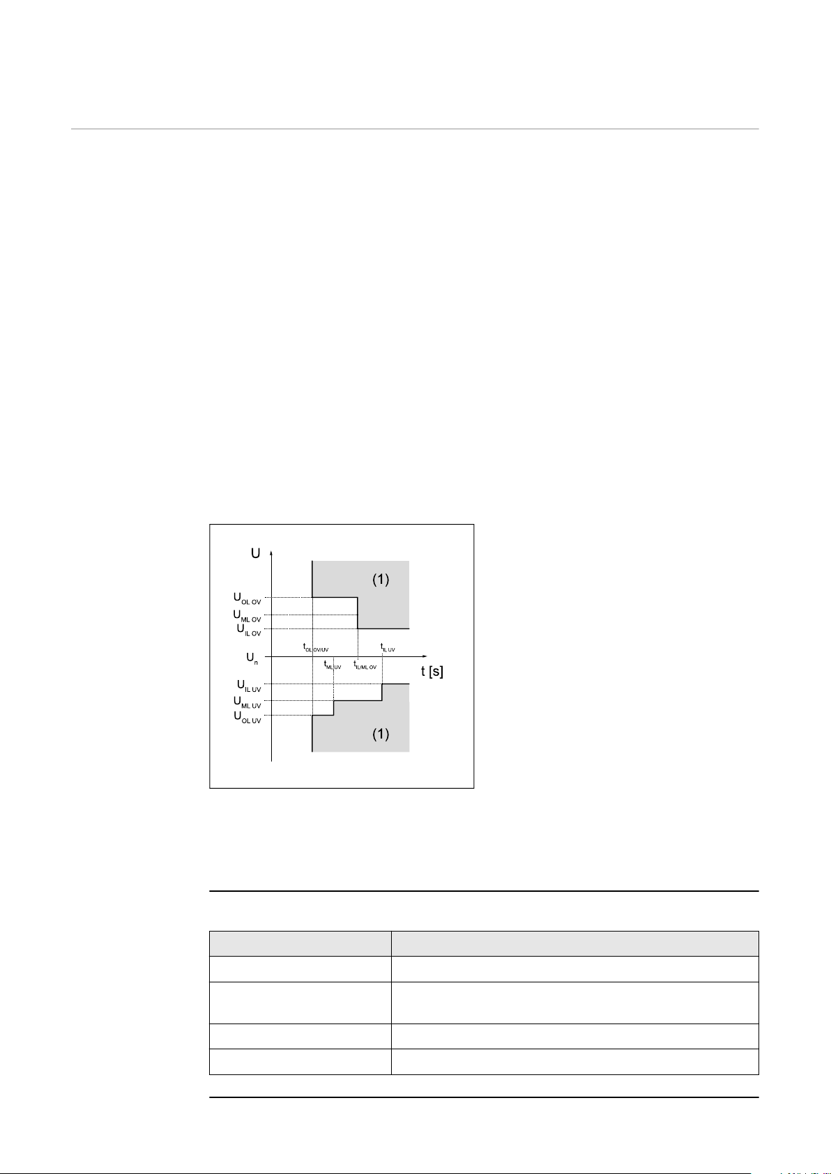
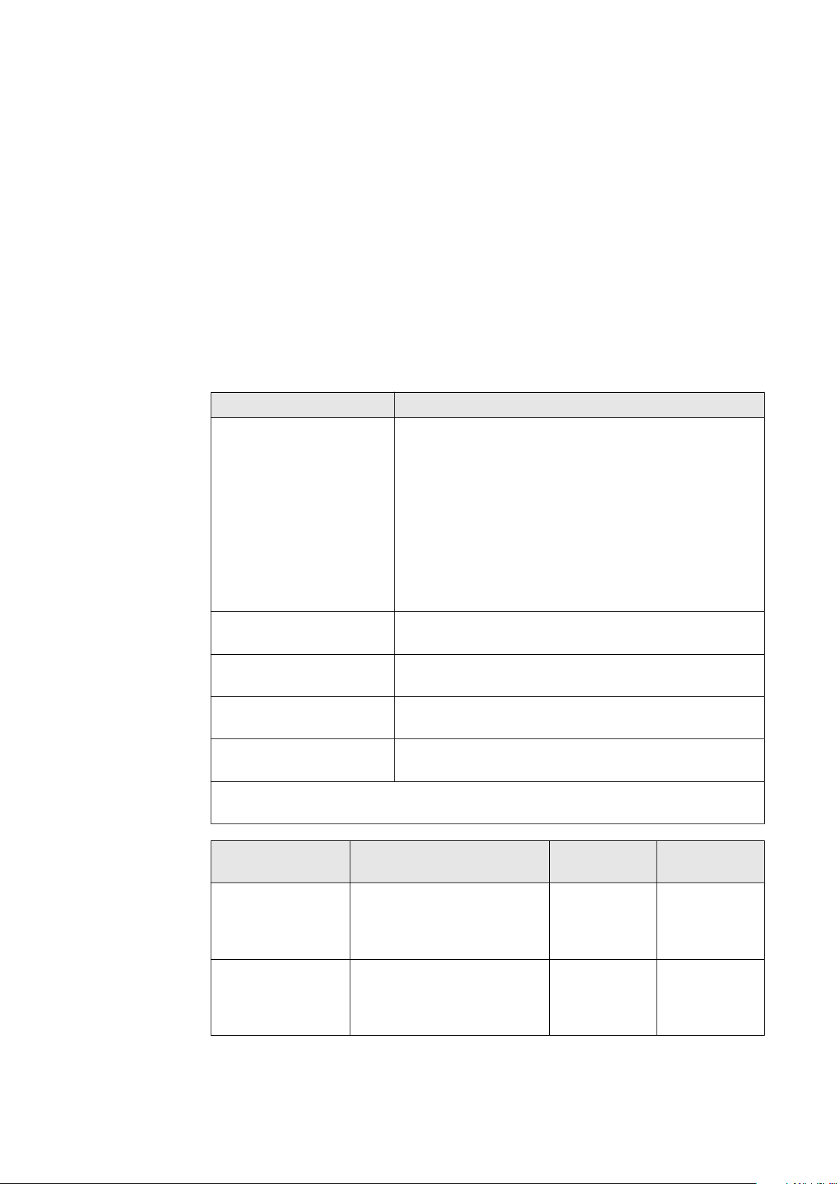
Three overvoltage and three undervoltage limit values can be used. The "Inner
Limits" (U< for undervoltage; U>for overvoltage) refer to those limit values which
are closer to the nominal voltage. The "Middle Limits" (U< for undervoltage;
U>for overvoltage) have a greater distance to the nominal voltage. The greatest
distance between the nominal voltage and the limit value is for the "Outer Lim-
its" (U<< for undervoltage; U>> for overvoltage).
For expedient use of the "Inner Limits" and "Outer Limits", the respective "In-
ner Limit" must be linked to a greater time than the "Outer Limit". If the "Middle
Limits" are also used, their time between "Inner Limit" and "Outer Limit" must
be set, see example in the diagram.
IL "Inner limit" - inner limit value
ML "Middle Limit" - middle limit
value
OL "Outer limit" - outer limit value
(1) Trip range
OV Overvoltage
UV Undervoltage
t
Graphic illustrating the limits
These voltage limit values are not active in backup power mode. Under "Device
configuration" → " Inverter" → "Backup power", the voltage limits that apply in
backup power mode can be configured.
"Inner Limits"
Protection time
x
20
Parameter Description
"Undervoltage U<" Setting value for undervoltage protection U< in [V]
"Undervoltage Time U<" Setting value of time for undervoltage protection
U< in [s]
"Overvoltage U>" Setting value for surge protection U> in [V]
"Overvoltage Time U>" Setting value of time for surge protection U> in [s]
"Middle Limits"
Parameter Description
"Voltage Middle Limits" Activate / deactivate the middle voltage limit values
"On" / "Off"
"Undervoltage U<" Setting value for undervoltage protection U< in [V]
"Undervoltage Time U<" Setting value of time for undervoltage protection
U< in [s]
"Overvoltage U>" Setting value for surge protection U> in [V]
"Overvoltage Time U>" Setting value of time for surge protection U> in [s]
"Outer Limits"
Parameter Description
"Voltage Outer Limits" Activate / deactivate the outer voltage limit values
"On" / "Off"
"Undervoltage U<<" Setting value for undervoltage protection U<< in [V]
"Undervoltage Time
U<<"
"Overvoltage U>>" Setting value for surge protection U>> in [V]
Setting value of time for undervoltage protection
U<< in [s]
EN
"Overvoltage Time U>>" Setting value of time for surge protection U>> in [s]
"Long Time Average Limit"
This function calculates a moving average voltage value over the set time and
compares it with the set overvoltage protection value. If the overvoltage protection value is exceeded, a disconnect occurs.
Parameter Description
"Long Time Average
Limit"
"Overvoltage Averaging
Time U>"
"Overvoltage U>" Setting value of the surge protection with average
"Fast Overvoltage Disconnect"
Fast overvoltage disconnect for voltage spikes that can respond within one period.
Parameter Description
Activate / deactivate the voltage average limit value
"On" / "Off"
Time period over which the average value is calculated in [s]. (If 0 s is set, the check is not active)
value formation U> in [V]
"Fast Overvoltage Disconnect"
"Fast Overvoltage Disconnect Time"
"Startup and Reconnection"
Before the inverter is allowed to connect, the connection conditions for voltage
Activate / deactivate fast RMS overvoltage disconnect (exceeding 135 % of rated voltage) "On" / "Off"
Setting value of time for fast surge protection (peak
value exceeded by 35 %) in [s]. This disconnect can
be configured in the time range of microseconds.
21
and frequency must be fulfilled for a certain time.
A distinction is made between:
"Startup": switching on the inverter during a normal startup process (e. g. at
-
sunrise) and
"Reconnection": the reconnection of the inverter after a grid fault (see table
-
"Grid faults") (e. g. if a fault occurs in the AC grid during the day which
causes the inverter to disconnect).
Which limit values are used when checking the connection conditions depends
on whether a mains fault has occurred and which "Mode" is defined. The "Mode"
only influences the limit values and not the monitoring time. The monitoring time
is determined by the parameters described in "General" / "Startup and Recon-
nection". The monitoring time used depends on whether it is "Startup" or "Reconnection" and applies equally to frequency and voltage limits. After the grid
monitoring has expired, the previously mentioned "Interface Protection" values
are active. In backup power mode these "Startup and Reconnection" parameters
are not active.
Parameter Description
"Mode" The following modes are available:
"Startup Values are used for Startup / Recon-
-
nection Values are used for Reconnection": In
a normal startup process, the startup values
are used as connection conditions. When reconnecting after a mains fault, the reconnection values are used as connection conditions.
"Startup Values are used for Startup and Re-
-
connection": Regardless of the type of con-
nection, the startup values are always used as
connection conditions.
"Reconnection Minimum Voltage"
"Reconnection Maximum Voltage"
"Startup Minimum
Voltage"
"Startup Maximum
Voltage"
The following errors are defined by the inverter as grid errors for this functionality:
Name Description "StateCode"
"Overvoltage" Mains voltage exceeds an
overvoltage limit ("Inner,
Middle, or Outer Limit
Overvoltage").
"Undervoltage" Mains voltage falls below
an undervoltage limit ("In-
ner, Middle or Outer Limit
Undervoltage").
Lower value of the voltage for reconnection in [V]
Upper value of the voltage for reconnection in [V]
Lower value of the voltage for the normal start process in [V]
Upper value of the voltage for the normal start process in [V]
"StateCode"
name
"AC voltage
too high"
"AC voltage
too low"
number
1114
1119
22

Name Description "StateCode"
name
"Overfrequency" Grid frequency exceeds an
overfrequency limit ("In-
ner, Outer or Alternative
Limit Overfrequency").
"AC frequency too
high"
"StateCode"
number
1035
EN
"Underfrequency"
"Fast Overvoltage Disconnect"
"Long Time Average Overvoltage
Limit"
"Unintentional Islanding Detection."
Frequency This chapter deals with the protection settings for overfrequencies and underfre-
quencies. Grid frequency limit values are defined for this purpose. These depend
on the country setup and can be adjusted as described below.
Grid frequency falls below
an underfrequency limit
("Inner, Outer or Alternat-
ive Limit Underfrequency").
Triggering of the fast surge
protection (> 135%).
Mains voltage exceeds the
long-term overvoltage limit ("Long Time Average
Limit").
Unintentional islanding
was detected.
"AC frequency too
low"
"Grid voltage
too high (fast
overvoltage
cut-out)"
"Long-term
mains
voltage limit
exceeded"
"Islanding
detected"
1037
1115, 1116
1117
1004
Each frequency limit value is defined by:
an underfrequency with associated protection time, or
-
an overfrequency with associated protection time.
-
The protection time describes the duration for which the frequency may be outside the respective frequency limit value before the inverter switches off with an
error message. Two overfrequency and two underfrequency limit values can be
used. The "Inner Limits" (f< for underfrequency; f>for overfrequency) are those
limit values which are closer to the rated frequency than the "Outer Limits" (f<<
for underfrequency; f>> for overfrequency). For the sensible use of both ranges,
the respective "Inner Limit" must be linked to a larger time than the "Outer Lim-
it".
23
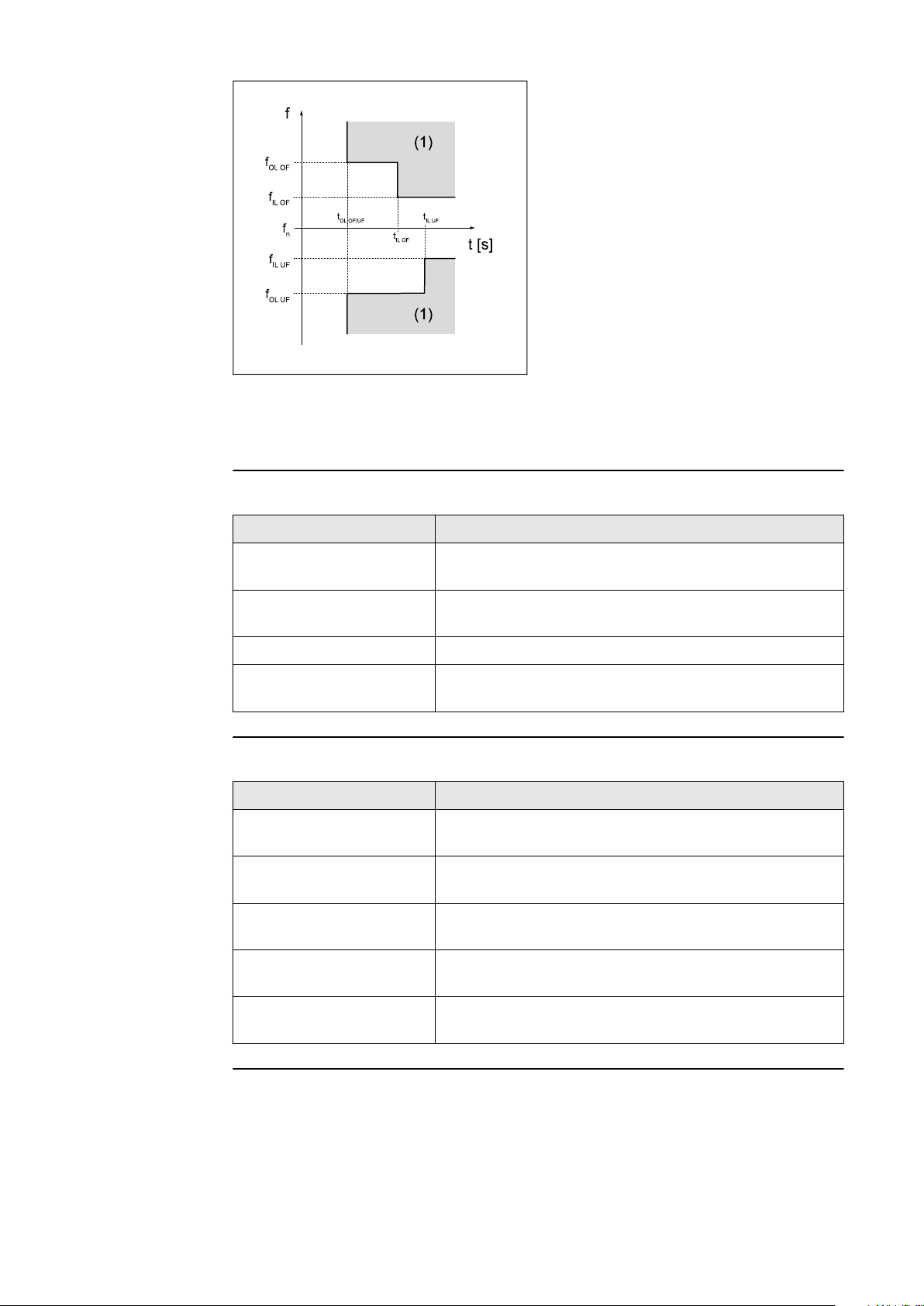
IL "Inner limit" - inner limit value
OL "Outer limit" - outer limit value
(1) Trip range
OF Overfrequency
UF Underfrequency
Graphic illustrating the limits
In backup power mode, the inverter itself determines the frequency and the frequency limits are therefore not active.
"Inner Limits"
Parameter Description
"Underfrequency f<" Setting value of underfrequency protection f< in
[Hz]
"Underfrequency Time
f<"
Setting value of time for underfrequency protection
f< in [s]
"Overfrequency f>" Setting value of overfrequency protection f> in [Hz]
"Overfrequency Time
f>"
Setting value of time for overfrequency protection
f> in [s]
"Outer Limits"
Parameter Description
"Frequency Outer Limits"
Activate / deactivate the outer frequency limits
"On" / "Off"
"Underfrequency f<<" Setting value of underfrequency protection f<< in
[Hz]
"Underfrequency Time
f<<"
Setting value of time for underfrequency protection
f<< in [s]
"Overfrequency f>>" Setting value of overfrequency protection f<< in
[Hz]
24
"Overfrequency Time
f>>"
Setting value of time for the overfrequency protection f>> in [s]
"Alternative Limits"
For the inner frequency limit values there is an additional second parameter set,
which is only relevant for Italy. In order to activate this second parameter set, the
alternative frequency limit value must be set to "On" on the user interface of the
inverter and activated/deactivated via an external signal as follows:
Activate: http://<IP>/status/SetSignaleEsterno
-
Deactivate: http://<IP>/status/ClearSignaleEsterno
-

Each time the inverter is restarted, the "Frequency Alternative Limit" does not
have to be set to "On" again, but the external signal to activate it must be sent
again. If it is not sent, the inner frequency limit value is used.
Parameter Description
EN
"Frequency Alternative
Limits"
"Underfrequency f<" Setting value of alternative underfrequency protec-
"Underfrequency Time
f<"
"Overfrequency f>" Setting value of alternative overfrequency protec-
"Overfrequency Time
f>"
"Startup and Reconnection"
Before the inverter is allowed to connect, the connection conditions for voltage
and frequency must be fulfilled for a certain time.
A distinction is made between:
"Startup": switching on the inverter during a normal startup process (e. g. at
-
sunrise) and
"Reconnection": the reconnection of the inverter after a grid fault (see table
-
"Grid faults") (e. g. if a fault occurs in the AC grid during the day which
causes the inverter to disconnect).
Activate / deactivate alternative frequency limit values "On" / "Off"
tion f< in [Hz]
Setting value of time for the alternative underfrequency protection f< in [s]
tion f> in [Hz]
Setting value of time for the alternative overfrequency protection f> in [s]
Which limit values are used when checking the connection conditions depends
on whether a mains fault has occurred and which "Mode" is defined. The "Mode"
only influences the limit values and not the monitoring time. The monitoring time
is determined by the parameters described in "General" / "Startup and Recon-
nection". The monitoring time used depends on whether it is "Startup" or "Reconnection" and applies equally to frequency and voltage limits. After the grid
monitoring has expired, the previously mentioned "Interface Protection" values
are active. In backup power mode these "Startup and Reconnection" parameters
are not active.
Parameter Description
"Mode" The following modes are available:
"Startup Values are used for Startup / Recon-
-
nection Values are used for Reconnection": In
a normal startup process, the startup values
are used as connection conditions. When reconnecting after a mains fault, the reconnection values are used as connection conditions.
"Startup Values are used for Startup and Re-
-
connection": Regardless of the type of con-
nection, the startup values are always used as
connection conditions.
"Startup Values are used for Reconnection":
-
When reconnecting after a mains fault, the
startup values are used as reconnection conditions. In a normal start-up procedure, the
"Frequency Inner Limits" f< and f>used as
connection conditions.
25

Parameter Description
"Reconnection Minimum Frequency"
"Reconnection Maximum Frequency"
"Startup Minimum Frequency"
"Startup Maximum Frequency"
The following errors are defined by the inverter as grid errors for this functionality:
Name Description "StateCode"
"Overvoltage" Mains voltage exceeds an
overvoltage limit ("Inner,
Middle, or Outer Limit
Overvoltage").
"Undervoltage" Mains voltage falls below
an undervoltage limit ("In-
ner, Middle or Outer Limit
Undervoltage").
Lower value of the grid frequency for reconnection
in [Hz]
Upper value of the grid frequency for reconnection
in [Hz]
Lower value of the grid frequency for the normal
start process in [Hz]
Upper value of the grid frequency for the normal
start process in [Hz]
"StateCode"
name
"AC voltage
too high"
"AC voltage
too low"
number
1114
1119
"Overfrequency" Grid frequency exceeds an
overfrequency limit ("In-
ner, Outer or Alternative
Limit Overfrequency").
"Underfrequency"
"Fast Overvoltage Disconnect"
"Long Time Average Overvoltage
Limit"
"Unintentional Islanding Detection."
"Rate of Change of Frequency (RoCoF) Protection"
This function allows the RoCoF (Rate of Change of Frequency) ‑detection and
‑switch-off to be activated and adjusted. In the event of frequency changes that
are above a set value and last longer than the set time, the inverter is shut down.
Grid frequency falls below
an underfrequency limit
("Inner, Outer or Alternat-
ive Limit Underfrequency").
Triggering of the fast surge
protection (> 135%).
Mains voltage exceeds the
long-term overvoltage limit ("Long Time Average
Limit").
Unintentional islanding
was detected.
"AC frequency too
high"
"AC frequency too
low"
"Grid voltage
too high (fast
overvoltage
cut-out)"
"Long-term
mains
voltage limit
exceeded"
"Islanding
detected"
1035
1037
1115, 1116
1117
1004
26

RoCoF detection can be used as a passive stand-alone operation detection method.
Parameter Description
EN
"Rate of Change of Frequency (RoCoF) Protection."
"ROCOF Limit" Setting value of the frequency change protection in
"RoCoF Time" Setting value of time for the RoCoF protection in [s]
DC Injection DC injection means the injection of an AC current into the public grid that is un-
intentionally contaminated with a DC component. This DC component causes a
shift of the pure AC current on the Y-axis (offset).
Due to the way the inverter works, no DC injection takes place in normal operation. However, in order to be protected against faults or inaccuracies, many connection rules require monitoring of the DC injection and shutdown if limit values
are exceeded.
Internal and external limits can be defined for the limit values. Inner limits have
tighter limits and longer protection times by default, outer limits have broader
limits and shorter protection times, so that shutdown occurs more quickly with
higher DC components. For both limit values there is a protection time which
defines the maximum overshoot duration.
"Inner Limit"
Activate and deactivate the RoCoF protection.
"On" / "Off
[Hz/s]
Range of val-
Parameter
"Mode" Off Monitoring of the inner limit is deactiv-
"DC Current
Absolute Value"
"DC Current
Relative Value"
ues Description
ated.
Absolute DC component monitoring with an abso-
lute current limit in [A].
Relative DC component monitoring with a relative
current limit in [%] referred to the nominal
current of the inverter.
0.0 A ‑ 10.0 A Absolute DC current limit in [A] - If the
DC component of the injected AC current
exceeds this limit for the duration defined
with "DC Injection Time", feeding energy
into the grid is interrupted with status
code 1052.
This limit only applies to the "Absolute"
mode.
0.0 % ‑ 10.0 % Relative DC current limit in [%] referred to
the nominal current of the inverter - If the
relative DC component of the injected AC
current exceeds this limit for the duration
defined with "DC Injection Time", feeding
energy into the grid is interrupted with
status code 1052.
This limit only applies to the "Relative"
mode.
27

Parameter
Range of values Description
"DC Injection
Time"
"Outer Limit"
Parameter
"Mode" Off Monitoring of the outer limit is deactiv-
"DC Current
Absolute Value"
0.0 s ‑ 10.0 s Protection time for the inner limit - Shutdown occurs after the respective limit
value has been exceeded for this time.
Range of values Description
ated.
Absolute DC component monitoring with an abso-
lute current limit in [A].
Relative DC component monitoring with a relative
current limit in [%] referred to the nominal
current of the inverter.
0.0 A ‑ 10.0 A Absolute DC current limit in [A] - If the
DC component of the injected AC current
exceeds this limit for the duration defined
with "DC Injection Time", feeding energy
into the grid is interrupted with status
code 1052.
This limit only applies to the "Absolute"
mode.
"DC Current
Relative Value"
"DC Injection
Time"
0.0 % ‑ 10.0 % Relative DC current limit in [%] referred to
the nominal current of the inverter - If the
relative DC component of the injected AC
current exceeds this limit for the duration
defined with "DC Injection Time", feeding
energy into the grid is interrupted with
status code 1052.
This limit only applies to the "Relative"
mode.
0.0 s ‑ 10.0 s Protection time for the outer limit - Shutdown occurs after the respective limit
value has been exceeded for this time.
28

Grid Support Functions
EN
Voltage Fault
Ride Through
(VFRT)
In the event of faults in the grid, there is a risk of a large number of generation
plants being shut down unintentionally and thus a risk of network collapse. Grid
voltage disturbances (Voltage Fault, Gridvoltage-Disturbance) are short-term
voltage dips or surges in the grid. These voltage changes go beyond the normal
range of the operating voltage (e.g. nominal voltage +/- 10 %). However, the duration of the voltage changes is short, so that the normal operating voltage is
reached again before the system is shut down (due to "Interface Protection").
Voltage Fault Ride Through means that the inverter can ride through such a grid
voltage fault without shutting down prematurely. If the shutdown conditions of
the protection settings ("Grid and system protection" or "Interface Protection")
are reached (time and value), the inverter always shuts down, thus terminating
VFRT operation. The requirements for the exact behaviour of the inverters during
the fault depend on the respective grid connection rules. The following parameters determine this behaviour.
Classification into regions
The voltage fault detection of the inverter detects severe or rapid mains voltage
fluctuations and classifies them into so-called regions according to the level of
the fault voltage (voltage level during the fault). Each region is assigned a specific
mains voltage value range. Three individual regions (R1, R2, R3) can be configured. Each individual region has an adjustable detection threshold and several
parameters that determine the behaviour of the inverter within that region. The
detection limit is a relative voltage level and is specified in percent derived from
the AC nominal voltage. A value above 100 % means that the associated region
describes an overvoltage disturbance (High Voltage Ride Through HVRT). A value
less than 100 % means that the associated region describes an undervoltage
fault (Low Voltage Ride Through LVRT). Figure 1 shows an example of a typical
arrangement of the three regions (shown here with horizontal bars) by selective
choice of detection thresholds: R1 threshold 110 %, R2 threshold 90 %, R3
threshold 40 %. The voltage range between the limits of Region1 and Region2
(white bar) comprises the voltage range for normal operation (here: 90 to 110 %
of the nominal voltage). Region 1 comprises overvoltage disturbances, Region 2
consists of slight undervoltage disturbances (from 90 to 40 %). Region 3 consists
of severe undervoltage disturbances (below 40 %).
Division of the grid voltage range into three fault regions by selecting the detection thresholds.
IMPORTANT!
The length of the bars represents trip times for overvoltage and undervoltage
29

detection of the "Interface Protection" function group. This has no significance
for the VFRT functionality.
Regions R1 to R3 must have descending values of detection thresholds:
The R1 threshold must be higher than the R2 threshold, and so on.
-
The use of identical thresholds for multiple regions is prohibited.
-
Using the threshold value 0 % is allowed.
-
To deactivate a specific region, its threshold can be used:
An HV region (R1) is deactivated by adjusting the threshold to 200 %. An unused
LV region (usually R3) is deactivated by adjusting the threshold to 0 %.
General VFRT settings
The following setting values apply equally to all regions.
Standard
Parameter Value range
"Mode" On VFRT function is active ac-
Off Off If no special behaviour is
value Description
cording to the set parameter values.
required during grid disturbances, the inverter will
behave according to the
default values in this table
with this setting. Any parameter settings made are
ignored.
"Reactive Current Limit for
Overexcited
Operation."
"Reactive Current Limit for
Underexcited
Operation."
0 ‑ 110
[% IacNominal]
0 ‑ 110
[% IacNominal]
100 % Limitation of the reactive
current during a mains
voltage fault and overexcited operation - in percent [%] related to the
nominal current lN.
This parameter is only effective for the current inrush mode "Active Asym-
metric Current".
100 % Limitation of the reactive
current during a mains
voltage fault and underexcited operation - in percent [%] related to the
nominal current lN.
This parameter is only effective for the current inrush mode "Active Asym-
metric Current".
30

Parameter Value range
"Sudden
Voltage Change
Detection"
On The detection of sudden
Off Off No detection of sudden
Standard
value Description
EN
voltage changes within the
normal voltage range is
active.
So-called sudden voltage
changes do not usually violate static voltage limits,
but are indicators of network disturbances.
voltage changes within the
normal voltage range.
"Insensitivity
Range"
"Deactivation
Time"
0 ‑ 100
[% Uac 1s‑Avg]
0 ‑ 100 [s] 5 s Time duration of mains
5 % Limit value that must be
exceeded by a sudden
change in voltage (change
in the positive sequence
voltage or negative sequence voltage) for a
mains voltage fault to be
detected. Reference value
for the calculation of this
limit value is the moving
average value of the mains
voltage over 1 second
(1s‑Avg).
fault handling for sudden
voltage changes. After this
time has elapsed, the
mains fault handling is
automatically terminated
if no static voltage limits
(see parameter "Threshold
Static" under Region 1, 2,
3) have been violated.
31

Region 1
These setting values define how the inverter behaves within Region 1. The choice
of setting has no effect on regions 2 and 3.
Standard
Parameter Value range
value Description
"Static
Threshold"
0 ‑ 200
[% UacNominal]
125 % Static voltage threshold
(in % of nominal voltage)
that must be exceeded or
fallen below to activate
VFRT Region 1 and its associated current inrush
mode.
> 100 % ... Region 1 is
-
used as the HVRT region.
< 100 % ... Region 1 is
-
used as the LVRT region.
Setting condition:
Threshold R1 > Threshold
R2 > Threshold R3
Default value 125 % means
that the inverter is in normal current feed-in operation up to 125 % of the
nominal voltage. VFRT becomes active above 125 %
with the selected current
inrush mode (default
mode for Region 1: "Zero
Current").
32

Parameter Value range
"Static Detection Mode"
Voltage system used for
L-N Voltage L-N Voltage The phase-to-neutral (line-
L-L Voltage The phase-to-phase (line-
Standard
value Description
EN
static threshold detection
of VFRT Region 1.
For three-phase devices,
the minimum value (for
LVRT regions) or the maximum value (for HVRT regions) from the individual
voltages is used in each
case.
to-neutral) voltage system
is used for static threshold
detection of VFRT Region
1.
to-line) voltage system is
used for static threshold
detection of VFRT Region
1.
L-L and L-N
Voltage
Both voltage systems
(line-to-neutral and lineto-line) are used for static
threshold detection of
VFRT Region 1.
33

Parameter Value range
Standard
value Description
"Current Calc
Mode"
Current inrush mode for
Region 1.
This parameter defines the
type of current feed during a Region 1 voltage
fault.
Passive The pre-fault active cur-
rent and reactive current
is maintained for as long as
the fault persists.
Zero Current Zero Cur-
rent
Active Symmetric Current
A symmetrical reactive
The alternating current is
adjusted to zero. There is
no effective or reactive
power feed-in during the
fault.
current (positive-sequence
system reactive current) is
fed into the grid. The
amount of the additional
reactive current results
from the "k-factor Posit-
ive Sequence" multiplied
by the amount of the
voltage dip. No active current is fed in.
"k-factor Positive Sequence"
Active Asymmetric Current
0 ‑ 10 2.0 Multiplication factor (k-
An additional reactive cur-
rent is fed into the grid. At
the same time, active current is fed in (whereby the
reactive current has priority). The amount of additional reactive current results from the k-factors
multiplied by the amount
of the voltage dip. If the
"k-factor Negative Sequence" is set to 0, the
feed is symmetrical. Otherwise, asymmetrical
faults are responded to
with an asymmetrical current in-feed.
factor) for the positive-sequence system reactive
current in Region 1.
Only applied with current
inrush mode "Active Sym-
metric Current" and "Active Asymmetric Current".
34

Standard
Parameter Value range
"k-factor Negative Sequence"
Region 2
These setting values define how the inverter behaves within Region 2. The choice
of setting has no effect on regions 1 and 3.
Parameter Value range
0 ‑ 10 2.0 Multiplication factor (k-
value Description
factor) for the negativesequence system reactive
current in Region 1.
Only applied with current
inrush mode "Active
Asymmetric Current". If
an asymmetrical feed is
required, this is usually set
to the same value as "k-
factor Positive Sequence".
If symmetrical supply is
required, this is set to 0.
Standard
value Description
EN
"Static
Threshold"
0 ‑ 200
[% UacNominal]
40 % Static voltage threshold
(in % of nominal voltage)
that must be exceeded or
fallen below to activate
VFRT Region 2 and its associated current inrush
mode.
> 100 % ... Region 2 is
-
used as the HVRT region.
< 100 % ... Region 2 is
-
used as the LVRT region.
Setting condition:
Threshold R1 > Threshold
R2 > Threshold R3
Default value 40 % means
that the inverter is in normal current feed-in operation up to 40 % of the
nominal voltage. VFRT becomes active above 40 %
with the selected current
inrush mode (default
mode for Region 2: "Zero
Current").
35

Parameter Value range
Standard
value Description
"Static Detection Mode"
Voltage system used for
static threshold detection
of VFRT Region 2.
For three-phase devices,
the minimum value (for
LVRT regions) or the maximum value (for HVRT regions) from the individual
voltages is used in each
case.
L-N Voltage L-N Voltage The phase-to-neutral (line-
to-neutral) voltage system
is used for static threshold
detection of VFRT Region
2.
L-L Voltage The phase-to-phase (line-
to-line) voltage system is
used for static threshold
detection of VFRT Region
2.
L-L and L-N
Voltage
Both voltage systems
(line-to-neutral and lineto-line) are used for static
threshold detection of
VFRT Region 2.
36

Parameter Value range
"Current Calc
Mode"
Current inrush mode for
Standard
value Description
EN
Region 2.
This parameter defines the
type of current feed during a Region 2 voltage
fault.
Passive The pre-fault active cur-
rent and reactive current
is maintained for as long as
the fault persists.
Zero Current Zero Cur-
rent
Active Symmetric Current
Active Asymmetric Current
A symmetrical reactive
An additional reactive cur-
The alternating current is
adjusted to zero. There is
no effective or reactive
power feed-in during the
fault.
current (positive-sequence
system reactive current) is
fed into the grid. The
amount of the additional
reactive current results
from the "k-factor Posit-
ive Sequence" multiplied
by the amount of the
voltage dip. No active current is fed in.
rent is fed into the grid. At
the same time, active current is fed in (whereby the
reactive current has priority). The amount of additional reactive current results from the k-factors
multiplied by the amount
of the voltage dip. If the
"k-factor Negative Sequence" is set to 0, the
feed is symmetrical. Otherwise, asymmetrical
faults are responded to
with an asymmetrical current in-feed.
"k-factor Positive Sequence"
0 ‑ 10 2.0 Multiplication factor (k-
factor) for the positive-sequence system reactive
current in Region 2.
Only applied with current
inrush mode "Active Sym-
metric Current" and "Active Asymmetric Current".
37

Parameter Value range
Standard
value Description
"k-factor Negative Sequence"
Region 3
These setting values define how the inverter behaves within Region 3. The choice
of setting has no effect on regions 1 and 2.
Parameter Value range
"Static
Threshold"
0 ‑ 10 2.0 Multiplication factor (k-
factor) for the negativesequence system reactive
current in Region 2.
Only applied with current
inrush mode "Active
Asymmetric Current". If
an asymmetrical feed is
required, this is usually set
to the same value as "k-
factor Positive Sequence".
If symmetrical supply is
required, this is set to 0.
Standard
value Description
0 ‑ 200
[% UacNominal]
0 % Static voltage threshold
(in % of nominal voltage)
that must be exceeded or
fallen below to activate
VFRT Region 3 and its associated current inrush
mode.
> 100 % ... Region 3 is
-
used as the HVRT region.
< 100 % ... Region 3 is
-
used as the LVRT region.
Setting condition:
Threshold R1 > Threshold
R2 > Threshold R3
Default value 0 % means
that Region 3 is disabled/
inactive.
38

Parameter Value range
"Static Detection Mode"
Voltage system used for
L-N Voltage L-N Voltage The phase-to-neutral (line-
L-L Voltage The phase-to-phase (line-
Standard
value Description
EN
static threshold detection
of VFRT Region 3.
For three-phase devices,
the minimum value (for
LVRT regions) or the maximum value (for HVRT regions) from the individual
voltages is used in each
case.
to-neutral) voltage system
is used for static threshold
detection of VFRT Region
3.
to-line) voltage system is
used for static threshold
detection of VFRT Region
3.
L-L and L-N
Voltage
Both voltage systems
(line-to-neutral and lineto-line) are used for static
threshold detection of
VFRT Region 3.
39

Parameter Value range
Standard
value Description
"Current Calc
Mode"
Current inrush mode for
region 3.
This parameter defines the
type of current feed during a region 3 voltage fault.
Passive The pre-fault active cur-
rent and reactive current
is maintained for as long as
the fault persists.
Zero Current Zero Cur-
rent
Active Symmetric Current
A symmetrical reactive
The alternating current is
adjusted to zero. There is
no effective or reactive
power feed-in during the
fault.
current (positive-sequence
system reactive current) is
fed into the grid. The
amount of the additional
reactive current results
from the "k-factor Posit-
ive Sequence" multiplied
by the amount of the
voltage dip. No active current is fed in.
"k-factor Positive Sequence"
Active Asymmetric Current
0 ‑ 10 2.0 Multiplication factor (k-
An additional reactive cur-
rent is fed into the grid. At
the same time, active current is fed in (whereby the
reactive current has priority). The amount of additional reactive current results from the k-factors
multiplied by the amount
of the voltage dip. If the
"k-factor Negative Sequence" is set to 0, the
feed is symmetrical. Otherwise, asymmetrical
faults are responded to
with an asymmetrical current in-feed.
factor) for the positive-sequence system reactive
current in Region 3.
Only applied with current
inrush mode "Active Sym-
metric Current" and "Active Asymmetric Current".
40

Parameter Value range
"k-factor Negative Sequence"
Active Power Voltage-dependent Power Control
or also called Volt/Watt function or P(U) function, causes a change in effective
power depending on the mains voltage. By reducing the effective power at high
mains voltage (or increasing the effective power at low mains voltage), an unintentional switch-off of the inverter due to the overvoltage or undervoltage limits
can be avoided. This makes the yield losses less than they would be if the inverter
was switched off.
0 ‑ 10 2.0 Multiplication factor (k-
Standard
value Description
EN
factor) for the negativesequence system reactive
current in Region 3.
Only applied with current
inrush mode "Active
Asymmetric Current". If
an asymmetrical feed is
required, this is usually set
to the same value as "k-
factor Positive Sequence".
If symmetrical supply is
required, this is set to 0.
When the function is activated and the specified grid voltage limit value is exceeded, the effective power
is reduced according to a defined gradient if the mains voltage is too high
-
(see example "System without storage" - red characteristic curve)
is increased according to a defined gradient if the mains voltage is too low
-
(only possible with hybrid inverters, see example "System with storage" -
green characteristic curve).
In the case of a hybrid inverter with active grid support activated ("Active Grid
Support"), additional scenarios arise:
If the output power has already been reduced to 0 W when the voltage is too
-
high and the voltage continues to rise, additional energy can be taken from
the national grid (the battery is thus charged, see "System with storage and
active grid support enabled" - blue characteristic curve in the lower "Power
Input" area).
If the charging power (drawn from the national grid) has been reduced to
-
0 W when the voltage is too low and the voltage continues to drop, additional
energy can be drawn from the battery to increase the output power (see ex-
ample "System with storage and active grid support enabled" - blue charac-
teristic curve in the upper "Power Output" area).
41

Examples of active grid support:
"System without storage"
(graph - red characteristic
curve) Description of the parameter
"Mode": On (without Hys-
-
teresis)
No battery in the system
-
"Active Grid Support": Off
-
"Calculation Mode": P
-
= Pm‑Pn(k*df)
max
(1) Momentary effective power when the
"Activation Threshold Overvoltage" is
reached: 50 % of Pn (equipment nominal power)
(2) "Activation Threshold Overvoltage":
250 V
(3) "Gradient Overvoltage": 7.5 %/V
"System with storage and active grid support disabled"
(graphic - green characteristic
curve) Description of the parameter
"Mode": On (without Hys-
-
teresis)
Battery is active
-
"Active Grid Support": Off
-
"Calculation Mode": P
-
= Pm‑Pn(k*df)
max
(1) (4) Momentary effective power when the
respective "Activation Threshold" is
reached: 50 % of Pn (equipment -
nominal power)
(2) "Activation Threshold Overvoltage":
250 V
(3) "Gradient Overvoltage": 7.5 %/V
(5) "Activation Threshold Undervoltage":
210 V
(6) "Gradient Undervoltage": 7.5 %/V
"System with storage and active grid support enabled"
(graphic - blue characteristic
curve) Description of the parameter
"Mode": On (without Hys-
-
teresis)
Battery is active
-
"Active Grid Support": On
-
"Calculation Mode": P
-
= Pm‑Pn(k*df)
max
(1) (4) Momentary effective power when the
respective "Activation Threshold" is
reached: 50 % of Pn (equipment -
nominal power)
(2) "Activation Threshold Overvoltage":
250 V
(3) "Gradient Overvoltage": 7.5 %/V
(5) "Activation Threshold Undervoltage":
210 V
(6) "Gradient Undervoltage": 7.5 %/V
42

General power curve depending on grid voltage.
SOC (State Of Charge) limits can be set for active grid support with battery. If a
limit is reached, the battery is no longer used for active grid support. These can
be found under "Battery SoC Limitation for Grid Support":
"Battery SoC Lower Limit" - The battery will not be further discharged when
-
the lower limit is reached.
"Battery SoC Upper Limit" - The battery will not be further charged when
-
the upper limit is reached.
EN
Parameter Value range Description Availability
"Mode" Off The function is deactiv-
ated.
On (without
The function is activated.
Hysteresis)
"Activation
Threshold
Overvoltage"
"Gradient Overvoltage"
208 ‑ 311 [V] Mains voltage limit value
above which the power reduction takes place.
0.01 ‑ 100 [%/V]Gradient by which the effective power is reduced.
Example - conversion from
static to gradient:
Static s = 4 % → Gradient k
= 1/(0.04*230 V) =
10.9 %/V
43

Parameter Value range Description Availability
"Calculation
Mode"
"Active Grid
Support"
P
=
max
Pm-Pm(k*dV)
Indicates the reference
power for calculating the
power limit in the event of
P
=
max
Pn-Pn(k*dV)
P
=
max
Pm-Pn(k*dV)
overvoltage or undervoltage.
Reference power:
Pm → Momentary
-
power when the
mains voltage limit
value is exceeded.
Pn → Nominal power
-
of the device.
Off Deactivates extended act-
ive mains support for
devices with a battery.
On Activates extended active
mains support for devices
with a battery.
Has no influence on
the following setups:
AUS
-
Region
A 2020
AUS
-
Region
B 2020
AUS
-
Region
C 2020
NZS
-
2020
"Activation
Threshold Undervoltage"
"Gradient Undervoltage"
"Time Constant
(τ)"
0 ‑ 311 [V] Mains voltage limit value
above which the power increase takes place.
0 ‑ 100 [%/V] Gradient by which the ef-
fective power increases.
Example - conversion from
static to gradient:
Static s = 4 % → Gradient k
= 1/(0.04*230 V) =
10.9 %/V
0 ‑ 600 [s] Time constant (1 Tau) in
seconds [s]. Whenever the
set value is changed, this
new set value is not
triggered abruptly, but
smoothly in accordance
with a PT1 response. The
time constant describes
how quickly the new set
value is reached. (After
three time constants the
final value 95 % is
reached)
44

Parameter Value range Description Availability
"Stop Voltage
at Overvoltage"
0 ‑ 311 [V] Mains voltage limit value
up to which the power reduction takes place. The
gradient is automatically
calculated from the parameters "Activation
Threshold Overvoltage"
and "Power at Stop
Voltage at Overvoltage".
The parameters "Gradient
Overvoltage" and "Calculation Mode" have no func-
tion.
"Power at Stop
Voltage - Overvoltage"
0 ‑ 100 [%] Reference power when the
set mains voltage limit
value is reached.
Example: Setups AUS/NSZ
2020 Description of the parameter
"Mode": On (without hys-
-
teresis)
(1) "Activation Threshold Overvoltage":
250 V
(2) "Stop at Voltage at Overvoltage":
260 V
(3) "Power at Stop Voltage - Over-
voltage": 20 %
Used exclusively in
the following setups:
AUS
-
Region
A 2020
AUS
-
Region
B 2020
AUS
-
Region
C 2020
NZS
-
2020
EN
Power curve when "Activation Threshold Overvoltage" is exceeded.
45

Parameter Value range Description Availability
"Stop Voltage
at Undervoltage"
200 ‑ 311 [V] Mains voltage limit value
up to which the charging
power of the battery is reduced. The gradient is calculated automatically
from the parameters "Ac-
tivation Threshold Undervoltage" and "Power at
Stop Voltage at Undervoltage". The parameters
"Gradient Undervoltage"
and "Calculation Mode"
have no function.
"Power at Stop
Voltage - Undervoltage"
0 ‑ 100 [%] Reference power when the
set mains voltage limit
value is reached. Only for
devices with battery in
charging mode.
Example: Setups AUS/NSZ
2020 Description of the parameter
"Mode": On (without hys-
-
teresis)
(1) "Activation Threshold Undervoltage":
210 V
(2) "Stop at Voltage at Undervoltage":
200 V
(3) "Power at Stop Voltage - Under-
voltage": 20 %
Used exclusively in
the following setups:
AUS
-
Region
A 2020
AUS
-
Region
B 2020
AUS
-
Region
C 2020
NZS
-
2020
46
Charge power limitation when "Activation Threshold Undervoltage" is exceeded.
Frequency-dependent Power Control
, also called frequency/watt function or P(f) function, causes a change in effective power depending on the grid frequency.
A distinction is made between:
Overfrequency
-
Underfrequency
-

When the function is activated and the specified grid frequency limit value is exceeded, the effective power
is reduced according to a defined gradient in the event of an overfrequency
-
(in the case of an inverter with an energy storage device, discharge of the
storage device is stopped first before the power of the PV generator is reduced).
is increased in the event of underfrequency in accordance with a defined
-
gradient (in the case of an inverter without an energy storage device or with
active grid support deactivated, only possible in conjunction with a manual
power reduction and corresponding priority).
The gradients result depending on the parameter "Configuration Method":
"Gradient": The gradient is given in %/Hz in relation to the device nominal
-
power or the momentary power when entering the function (see example 1).
"Stop Frequency": With this method, the gradient always results from the
-
current power at entry to the function to the stop frequency set in the setup
and power at stop frequency (see example 2).
In the case of an inverter with an energy storage device and active grid support
activated, additional scenarios arise:
If the output power has already been reduced to 0 W at overfrequency and
-
the frequency continues to rise, additional energy can be drawn from the grid
(the battery is thus charged).
If the charging power (drawn from the grid) is reduced to 0 W at underfre-
-
quency and the frequency continues to drop, additional energy can be drawn
from the battery to increase the output power.
EN
SOC (State Of Charge) limits can be set for active grid support with battery.
These can be found under "Battery SoC Limitation for Grid Support":
"Battery SoC Lower Limit" - The battery will not be further discharged when
-
the lower limit is reached.
"Battery SoC Upper Limit" - The battery will not be further charged when
-
the upper limit is reached.
Once the grid frequency falls within the permitted frequency range again following successful power reduction, return to the full power available takes place depending on the country setup as follows:
Mode: "On (without Hysteresis)"
-
The inverter increases the power from the current reduced value to the original value in accordance with the same gradient used for power reduction.
Mode: "On (with Hysteresis)"
-
The inverter will not increase the power to the original value until the frequency is back in the target value range for a specific length of time.
47

Example 1 Description of the parameter
"P(f) Mode": On (without
-
Hysteresis)
"Configuration Method":
-
Gradient
"Active Grid Support": Off
-
"Calculation Mode Under-
-
frequency": P
max
= Pm-
Pn(k*df)
"Calculation Mode Over-
-
frequency": P
max
= Pm-
Pn(k*df)
(1) Momentary effective power when the
respective "Activation Threshold" is
reached: 60 % of Pn (nominal power).
(2) "Gradient Underfrequency": 80 %/Hz
- Increase of output power without
battery only possible if sufficient
power from PV generator is available
and manual power limitation is active.
For this purpose, the "Priority at Un-
derfrequency" parameter must be set
to "Priority on Frequency-dependent
Power Limitation".
(3) "Activation Threshold Underfre-
quency": 49.7 Hz
(4) "Gradient Overfrequency": 60%/Hz
(5) "Activation Threshold Overfre-
quency": 50.3 Hz
48
General power curve with overfrequency and underfrequency without hysteresis with gradients.

Example 2 Description of the parameter
"P(f) Mode": On (without
-
Hysteresis)
"Configuration Method":
-
Stop frequency
"Active Grid Support": Off
-
(1) Momentary effective power when the
respective "Activation Threshold" is
reached: 60 % of Pn (nominal power).
(2) "Activation Threshold Underfre-
quency": 49.7 Hz
(3) "Stop Frequency - Underfrequency":
49.0 Hz
(4) "Power at Stop Frequency - Underfre-
quency": 85 %
(5) "Activation Threshold Overfre-
quency": 50.3 Hz
(6) "Stop Frequency - Overfrequency":
51.3 Hz
(7) "Power at Stop Frequency - Overfre-
quency": 20 %
EN
General power curve with overfrequency and underfrequency without hysteresis with stop frequency.
49

Example 3 Description of the parameter
"P(f) Mode": On (with Hys-
-
teresis)
"Configuration Method":
-
Gradient
"Active Grid Support": Off
-
"Calculation Mode Under-
-
frequency": P
max
= Pm-
Pn(k*df)
"Calculation Mode Over-
-
frequency": P
max
= Pm-
Pn(k*df)
(1) Momentary effective power when the
respective "Activation Threshold" is
reached: 60 % of Pn (nominal power).
(2) "Gradient Underfrequency": 80 %/Hz
(3) "Activation Threshold Underfre-
quency": 49.7 Hz
(4) "Lower Deactivation Threshold Un-
derfrequency": 49.9 Hz
(5) "Upper Deactivation Threshold Un-
derfrequency": 50.1 Hz
(6) "Gradient Overfrequency": 60 %/Hz
(7) "Activation Threshold Overfre-
quency": 50.3 Hz
(8) "Lower Deactivation Threshold Over-
frequency": 49.9 Hz
(9) "Upper Deactivation Threshold Over-
frequency": 50.1 Hz
(10) "Deactivation Time": 30 s
50
General power curve with overfrequency and underfrequency with hysteresis with gradients.

Parameter Value range Description Availability
"Mode"
"Configuration
Method"
Off The function is deactiv-
ated.
On (with Hysteresis)
On (without
Hysteresis)
Gradient For calculating the power
Function is activated with
hysteresis.
Function is activated
without hysteresis.
limitation depending on
the parameters "Gradient
Overfrequency" or "Gradient Underfrequency".
In the following
setups "On
(without
Hysteresis)"
is not possible:
AUS
-
Region
A 2020
AUS
-
Region
B 2020
AUS
-
Region
C 2020
NZS
-
2020
EN
"Active Grid
Support"
Stop - Frequency
Off Deactivates extended act-
On Activates extended active
The gradient is calculated
automatically using the
parameters "Stop Fre-
quency - Overfrequency"
and "Power at Stop Fre-
quency - Overfrequency"
as well as "Stop Fre-
quency - Underfrequency"
and "Power at Stop Fre-
quency - Underfrequency".
ive mains support for
devices with a battery.
mains support for devices
with a battery.
Has no influence on
the following setups:
AUS
-
Region
A 2020
AUS
-
Region
B 2020
AUS
-
Region
C 2020
NZS
-
2020
51

Overfrequency
Parameter Value range Description Availability
"Calculation
Mode Overfrequency"
"Activation
Threshold
Overfrequency"
"Gradient Overfrequency"
P
=
max
Pm-Pm(k*df)
Indicates the reference
power for calculating the
power limit in the event of
P
=
max
overfrequency.
Pn-Pn(k*df)
P
=
max
Pm-Pn(k*df)
Reference power
Pm → Momentary
-
power when the frequency limit value is
exceeded.
Pn → Nominal power
-
of the device.
45 ‑ 66 [Hz] Frequency limit value
above which the power reduction takes place.
0.01 ‑ 300 [%/
Hz]
Gradient by which the effective power is reduced.
Example - conversion from
static to gradient:
Static s = 5 % → Gradient k
= 1/(0.05*50Hz) =
40 %/Hz
"Stop Frequency - Overfrequency"
"Power at Stop
Frequency Overfrequency"
"Upper Deactivation Threshold
Overfrequency"
45 ‑ 66 [Hz] Frequency value at which
the power reduction ends.
-100 ‑ 0 [%] Power when the set frequency limit value "Stop
Frequency - Overfrequency" is reached. Ad-
justable between 0 % and
full charging power
(-100 %).
45 ‑ 66 [Hz] In use if "Mode" - "On
(with Hysteresis)" is set.
If the grid frequency falls
below this value, the frequency-dependent power
reduction is terminated,
taking into account the
settings under "Fre-
quency-dependent Power
Control - General".
52

Parameter Value range Description Availability
"Lower Deactivation Threshold
Overfrequency"
"Transition Frequency at Overfrequency"
45 ‑ 66 [Hz] Used when "Mode" is set
to "On (with Hysteresis)".
If this value is less than
the "Upper Deactivation
Threshold Overfrequency", a frequency win-
dow results in which the
grid frequency must be
located to terminate the
function. If this value is
greater than or equal to
the "Upper Deactivation
Threshold Overfrequency", it is not applied.
45 ‑ 66 [Hz] Frequency at which the
device with active battery
reaches an output power
of 0 W. If the grid frequency continues to rise,
energy is drawn from the
national grid and thus the
battery is charged. If there
is no battery in the system
or it is not active, this
parameter has no function
(behaviour as in example 3
- overfrequency).
Used exclusively in
the following setups:
AUS
-
Region
A 2020
AUS
-
Region
B 2020
AUS
-
Region
C 2020
NZS
-
2020
EN
53

Example 4: Setups AUS/NSZ
2020 Description of the parameter
"P(f) Mode": On (with Hys-
-
teresis)
"Active Grid Support": On
-
Battery is active
-
(1) Momentary effective power when the
respective "Activation Threshold" is
reached: 60 % of Pn (nominal power).
(2) The gradient for power reduction in
generator-powered operation at overfrequency results automatically from
the two set parameters "Activation
Threshold Overfrequency" and
"Transition Frequency at Overfrequency"
(3) "Activation Threshold Overfre-
quency": 50.25 Hz
(4) "Transition Frequency at Overfre-
quency": 50.75 Hz
(5) The gradient for increasing the char-
ging power at overfrequency results
automatically from the two set parameters "Transition Frequency at
Overfrequency" and "Stop Frequency
- Overfrequency". Depending on the
set country setup, the power at stop
frequency refers to drawing 100 %
from the national grid. The parameter
"Power at Stop Frequency - Overfrequency" has no function in these
countries.
(6) "Stop Frequency - Overfrequency":
52.0 Hz
(7) "Upper Deactivation Threshold Over-
frequency": 50.0 Hz - When the grid
frequency returns to or below the set
limit value, the effective power may be
increased again.
(8) "Deactivation Time": 20 s - The fre-
quency must be in the valid range for
at least this time before the function
is terminated.
(9) "Return Gradient 1": Return to power
before entering P(f) in percent per
second.
54

Power curve at overfrequency with hysteresis.
EN
Underfrequency
Parameter Value range Description Availability
"Calculation
Mode Underfrequency"
P
=
max
Pm-Pm(k*df)
P
=
max
Pn-Pn(k*df)
P
=
max
Pm-Pn(k*df)
Indicates the reference
power for calculating the
power limit in the event of
underfrequency.
Reference power
Pm → Momentary
-
power when the frequency limit value is
exceeded.
Pn → Nominal power
-
of the device.
"Activation
Threshold Underfrequency"
"Gradient Underfrequency"
45 ‑ 66 [Hz] Frequency limit value
above which the power increase takes place.
0 ‑ 100 [%/Hz] Gradient by which the ef-
fective power increases.
Example - conversion from
static to gradient:
Static s = 5 % → Gradient k
= 1/(0.05*50Hz) =
40 %/Hz
"Stop Frequency - Underfrequency"
45 ‑ 66 [Hz] Frequency value at which
the power increase ends.
55

Parameter Value range Description Availability
"Power at Stop
Frequency - Underfrequency"
"Upper Deactivation Threshold
Underfrequency"
"Lower Deactivation Threshold
Underfrequency"
0 ‑ 100 [%] Power when the set fre-
quency limit value "Stop
Frequency - Underfrequency" is reached. Ad-
justable between 0 % and
full feed-in power (100 %).
45 ‑ 66 [Hz] Used when "Mode" is set
to "On (with Hysteresis)".
If this value is greater than
the "Lower Deactivation
Threshold Underfrequency", there is a fre-
quency window in which
the grid frequency must
be to terminate the function. If this value is less
than or equal to the
"Lower Deactivation
Threshold Underfrequency", it is not applied.
45 ‑ 66 [Hz] In use when "Mode" - "On
(with Hysteresis)" is set.
If the grid frequency exceeds this value, the function is terminated, taking
into account the settings
under "Frequency-de-
pendent Power Control General".
"Transition Frequency at Underfrequency"
45 ‑ 66 [Hz] Frequency at which the
device with active battery
reaches an output power
of 0 W (charging power is
reduced). If the grid frequency continues to drop,
additional energy is released into the grid. This
energy can come from the
PV generator or from the
battery. If there is no battery in the system or it is
not active, this parameter
has no function (behaviour
as in example 3 - underfrequency).
Used exclusively in
the following setups:
AUS
-
Region
A 2020
AUS
-
Region
B 2020
AUS
-
Region
C 2020
NZS
-
2020
56

Example 5: Setups AUS/NSZ
2020 Description of the parameter
"P(f) Mode": On (with Hys-
-
teresis)
"Active Grid Support": On
-
Battery is active
-
(1) Momentary draw (charging power of
the battery) when the respective "Activation Threshold" (3) is reached:
80 % of Pn (nominal power)
(2) The gradient for reducing the charging
power at underfrequency results automatically from the two set parameters
"Activation Threshold Underfrequency" (3) and "Transition Frequency at Underfrequency" (4)
(3) "Activation Threshold Underfre-
quency": 49.75 Hz
(4) "Transition Frequency at Underfre-
quency": 49.0 Hz
(5) The gradient for increasing the output
power at underfrequency results automatically from the two set parameters
"Transition Frequency at Underfrequency" (4) and "Stop Frequency Underfrequency" (6). Depending on
the set country setup, the power at
stop frequency refers to 100 % output
power (nominal power of the inverter).
The parameter "Power at Stop Fre-
quency - Underfrequency" has no
function in these countries.
(6) "Stop Frequency - Underfrequency":
48.0 Hz
(7) "Lower Deactivation Threshold Un-
derfrequency": 50.0 Hz - When the
grid frequency returns to or above the
set limit value, the effective power
may return to the value before entering the function.
(8) "Deactivation Time": 20 s - The fre-
quency must be in the valid range for
at least this time before the function
is terminated.
(9) "Return Gradient 1": Return to power
before entering P(f) in percent per
second.
EN
57

Power curve at underfrequency with hysteresis.
General - Frequency-dependent Power Control
Parameter Value range Description Availability
"Return Gradient 1"
"Return Gradient 1 Alternative"
0.01 ‑ 100 [%/s]Rate of change at which
the inverter increases the
effective power after the
limitation has ended.
0.01 ‑ 100 [%/s]Rate of change at which
the inverter increases the
effective power after the
limitation has ended. This
is activated if the difference between the rated
power and the current reduced power is greater
than the "Return Gradient
1 Alternative Threshold".
58

Parameter Value range Description Availability
"Return Gradient 1 Alternative Threshold"
0 ‑ 100 [W%] Threshold value from
which "Return Gradient 1"
or "Return Gradient 1 Al-
ternative" is applied.
Example:
If the difference between
the rated power and the
currently reduced power is
less than or equal to the
threshold value, "Return
Gradient 1" is applied. If
the difference between
the rated power and the
current reduced power is
greater than or equal to
the threshold, "Return
Gradient 1 Alternative" is
applied. 0.01 - 100 %.
100 % means that "Return
Gradient 1" is always ap-
plied.
EN
59

Example 6 Description of the parameter
P
Actual power at the moment the limit
m
value is exceeded
P
Reduced power
red
(1) "Gradient Overfrequency"
(2) "Deactivation Time"
(3) "Return Gradient 1"
(4) "Return Gradient 1 Alternative"
(5) "Return Gradient 1 Alternative
Threshold": Pm - P
<= 25 %
red
(6) "Return Gradient 1 Alternative
Threshold": Pm - P
> 25 %
red
(7) "Intentional Delay"
The grid frequency returns to the permissible
range at P
red
.
After the waiting time (2) has elapsed, the
power is increased to the initial value Pm with
one of the following gradients:
Gradient 1 - red
The difference between the current power
Pm and the reduced power P
is ≤ "Return
red
Gradient 1 Alternative Threshold" of 25 %
(5). Thus, the power is increased to the initial
value Pm with "Return Gradient 1" (3).
Gradient 2 - grey
The difference between the current power
Pm and the reduced power P
is > "Return
red
Gradient 1 Alternative Threshold" of 25 %
(5). This increases the power to the output
value Pm with "Return Gradient 1 Alternat-
ive" (4).
60
Application example with "Return Gradient 1 Alternative" and "Return Gradient 1 Alternative
Threshold".

Parameter Value range Description Availability
"Return Gradient 2 Mode"
"Return Gradient 2"
Off Deactivates the use of
"Return Gradient 2". Rais-
ing the effective power
from the reduced value to
the device rated output
takes place according to
"Return Gradient 1".
On Activates a different rate
of change at which the inverter increases the effective power from the original value to the device
nominal output. Raising
the effective power from
the original value to the
device rated output takes
place according to "Return
Gradient 2".
0.01 ‑ 100 [%/s]Rate of change at which
the inverter increases the
effective power from the
original value to the device
nominal output.
EN
Example 7 Description of the parameter
"Return Gradient 2 Mode"
-
= On
P
Actual power at the moment the limit
m
value is exceeded
P
Reduced power
red
(1) "Gradient Overfrequency"
(2) "Deactivation Time"
(3) "Return Gradient 1"
(4) "Return Gradient 2"
(5) "Intentional Delay"
At P
the grid frequency returns to the per-
red
missible range. After the end of the waiting
time (2), the power is increased to the initial
value Pm with "Return Gradient 1". The
power is then increased to the device nominal
output Pn with "Return Gradient 2" (4).
61

Application example with "Return Gradient 2 Mode".
Parameter Value range Description Availability
"Deactivation
Time"
"Intentional
Delay"
"Time Constant
(τ)"
0 ‑ 600 [s] Used when "Mode" is set
to "On (with Hysteresis)".
Waiting time after which
the inverter increases the
power again (after the grid
frequency is again within
the permitted frequency
range between "Upper De-
activation Threshold" and
"Lower Deactivation
Threshold").
0.5 ‑ 60 [s] Delays the start of the frequency-dependent power
control after exceeding
the respective "Activation
Threshold".
0 ‑ 60 [s] Time constant (1 Tau) in
seconds [s]. Whenever the
set value is changed, this
new set value is not
triggered abruptly, but
smoothly in accordance
with a PT1 response. The
time constant describes
how quickly the new set
value is reached. (After
three time constants the
final value 95 % is
reached)
62

Battery SoC Limitation for Grid Support
Parameter Value range Description Availability
"Mode" Off Deactivated SoC limitation
On Activated SoC limitation
"Battery SoC
Lower Limit"
"Battery SoC
Upper Limit"
General - Active Power
Parameter Value range Description Availability
"Priority at Underfrequency"
0 ‑ 100 % The battery is not further
discharged when the lower
limit is reached.
0 ‑ 100 % The battery is no longer
charged when the upper
limit is reached.
Priority on
Manual Power
Limitation
Priority on
Frequency-dependent Power
Limitation
With "Priority on Manual
Power Limitation" the
power is not increased
above the set limit in case
of underfrequency.
With "Priority on Fre-
quency-dependent Power
Limitation" the manual
power limitation is ignored
in case of underfrequency
and the output power is increased depending on the
frequency. The prerequisite is that sufficient energy
is available from the PV
generator or the battery.
EN
Reactive Power The voltage in the national grid can be influenced by the controlled use of react-
ive power by the inverter. When using reactive power control, the effective power
generated at the same time is not affected or is only affected to a small extent.
IMPORTANT!
The exchange of reactive power (in addition to the feed-in of effective power) increases the current by the factor 1/cos φ.
Largely regardless of the effective power and therefore regardless of the energy
yield, switching the reactive power can cause the voltage to both rise and to fall:
In over-excited mode or capacitive mode, reactive power is supplied to the
-
national grid. This increases the mains voltage.
In under-excited mode or inductive mode, reactive power is taken from the
-
inverter. The mains voltage is lowered as a result.
63

Potential operating range
Reactive power mode is restricted by the maximum apparent power Sn (and the
maximum output current) as well as by the operational reactive power limits of
the inverter:
Primo GEN24: Q
-
Symo GEN24: Q
-
Tauro: Q
-
= 100 % of Sn (or cos φ = 0.00)
max
= 60 % of Sn (or cos φ = 0.80 at Sn)
max
= 71 % of Sn (or cos φ = 0.70 at Sn)
max
The value range specified for the following parameters may be additionally limited by the selected country-specific settings.
The following figure shows the possible operating range of the inverter. All valid
operating points defined by effective power P and reactive power Q are within
the grey area.
Example: Primo GEN24
64

General settings
Parameter
"Mode"
Range of values Description
Reactive power mode selection option.
The following modes are described in the
subchapters.
Off No reactive power is fed in.
Cos φ - Constant Power
Factor
Q Absolute Constant Reactive Power
Q Relative Constant Reactive Power
Cos φ(P) Power dependent Power
Factor Characteristic
Q(P) - Power
dependent Reactive Power
Characteristic
Constant Cos φ.
Constant reactive power in [Var].
Constant reactive power in percent [%] of
Sn.
Effective power-dependent Cos φ control.
Effective power-dependent reactive power
control.
EN
"P/Q Priority"
"Cos φ Minimum"
Q(U) - Voltage
dependent Reactive Power
Characteristic
Q Priority When the maximum apparent power is
P Priority The setting "P Priority" leads to a reduc-
0 ‑ 1 Minimum cos φ, which together with the
Mains voltage dependent reactive power
control.
reached, the setting "Q Priority" leads to a
reduction of the effective power in favour
of reaching the reactive power specification.
tion of the reactive power in favour of
reaching the available effective power
when the maximum apparent power is
reached.
maximum apparent power forms an additional limitation of the reactive power at
low effective power.
65

Depending on the selected mode, only the setting options in the respective
subchapter and these general settings have an effect.
const cos φ
Reactive power default defined by a constant cos φ. The function is limited by the
maximum apparent power and Cos φ minimum, the P/Q priority has no effect.
Range of val-
Parameter
ues Description
"cos φ - Power
Factor"
"Direction / Excitation"
"Time Constant
(τ)"
0 ‑ 1 Set value of Cos φ
The current direction corresponds to the
generator counter arrow system.
Over-Excited Over-excited operation = capacitive opera-
tion = reactive power is supplied = reactive
current is fed in lagging the active current.
Under-Excited Under-excited operation = inductive oper-
ation = reactive power is drawn = reactive
current is fed in ahead of the active current.
0.01 s ‑ 60 s Time constant (1 Tau) in seconds [s].
Whenever the set value is changed, this
new set value is not triggered abruptly, but
smoothly in accordance with a PT1 response. The time constant describes how
quickly the new set value is reached. (After
three time constants the final value 95 %
is reached)
66

Q Absolute - Constant Reactive Power
Reactive power specification defined by a constant value [Var]. The function is
limited by the maximum apparent power and by "Cos φ Minimum"
Range of val-
Parameter
ues Description
EN
"Q - Reactive
Power (Var)"
"Time Constant
(τ)"
-200,000 Var -
200,000 Var
0.01 s ‑ 60 s Time constant (1 Tau) in seconds [s].
Reactive power setting value in [Var] (set
value)
Whenever the set value is changed, this
new set value is not triggered abruptly, but
smoothly in accordance with a PT1 response. The time constant describes how
quickly the new set value is reached. (After
three time constants the final value 95 %
is reached)
Q Relative - Constant Reactive Power
Reactive power specification defined by a constant value in percent [%], related
67

to the nominal apparent power (Sn) of the inverter. The function is limited by the
maximum apparent power and by "Cos φ Minimum".
Range of val-
Parameter
ues Description
"Q - Reactive
Power (% of
Nominal Apparent Power)"
"Time Constant
(τ)"
-100 % -
100 %
0.01 s ‑ 60 s Time constant (1 Tau) in seconds [s].
Reactive power setting as a percentage [%]
in relation to the nominal apparent power
(set value)
Whenever the set value is changed, this
new set value is not triggered abruptly, but
smoothly in accordance with a PT1 response. The time constant describes how
quickly the new set value is reached. (After
three time constants the final value 95 %
is reached)
Cos φ(P) - Power dependent Power Factor Characteristic
This function controls the cos φ depending on the momentary effective power
according to a characteristic curve. The characteristic curve is defined by four
data points (1‑2‑3‑4). If fewer data points are required, the identical parameters
can be set for two points. The function is limited by the maximum apparent
68

power and by "Cos φ Minimum". For the characteristic curves, the data points
must be entered in the X‑axis (effective power) and in the Y‑axis (Cos φ).
Range of val-
Point Parameter
ues Description
EN
1
2
"Active Power
(% of Nominal
Apparent
Power)"
"cos φ - Power
Factor"
"Direction / Excitation"
Under-Excited Under-excited operation = in-
"Active Power
(% of Nominal
Apparent
Power)"
"cos φ - Power
Factor"
"Direction / Excitation"
0 % ‑ 100 % Effective power in percent
[%] related to the nominal apparent power Sn.
0 ‑ 1 Set value of Cos φ.
The current direction corres-
ponds to the generator
counter arrow system.
ductive operation = reactive
power is drawn = reactive current is fed in ahead of the
active current.
Over-Excited Over-excited operation = ca-
pacitive operation = reactive
power is supplied = reactive
current is fed in lagging the
active current.
0 % ‑ 100 % Effective power in percent
[%] related to the nominal apparent power SN.
0 ‑ 1 Set value of Cos φ.
The current direction corres-
ponds to the generator
counter arrow system.
Under-Excited Under-excited operation = in-
ductive operation = reactive
power is drawn = reactive current is fed in ahead of the
active current.
Over-Excited Over-excited operation = ca-
pacitive operation = reactive
power is supplied = reactive
current is fed in lagging the
active current.
69

Point Parameter
Range of values Description
3
4
"Active Power
(% of Nominal
Apparent
Power)"
"cos φ - Power
Factor"
"Direction / Excitation"
"Active Power
(% of Nominal
Apparent
Power)"
"cos φ - Power
Factor"
"Direction / Excitation"
0 % ‑ 100 % Effective power in percent
[%] related to the nominal apparent power SN.
0 ‑ 1 Set value of Cos φ.
The current direction corres-
ponds to the generator
counter arrow system.
Under-Excited Under-excited operation = in-
ductive operation = reactive
power is drawn = reactive current is fed in ahead of the
active current.
Over-Excited Over-excited operation = ca-
pacitive operation = reactive
power is supplied = reactive
current is fed in lagging the
active current.
70

Example: Curve defined by four data points.
1 P = 15 %, cos φ = 0.85 - Over-Excited
2 P = 25 %, cos φ = 1 - Over-Excited
3 P = 45 %, cos φ = 1 - Over-Excited
4 P = 90 %, cos φ = 0.9 - Under-Excited
General
In addition to the four points, the following parameters also come into play:
EN
Parameter
"Lock-In
Voltage-Dependent (% of
Nominal
Voltage)"
"Lock-Out
Voltage-Dependent (% of
Nominal
Voltage)"
Range of values Description
0 % ‑ 120 % AC voltage in per-
cent [%] related to
the nominal voltage.
If this value is exceeded, the Cos φ(P)
characteristic is activated.
0 % ‑ 120 % AC voltage in per-
cent [%] related to
the nominal voltage.
If this value is undershot, the Cos φ(P)
characteristic is deactivated. The lockout limit has priority
over the lock-in limit.
Supplementary description
With the voltage-dependent Lock-In/
Lock-Out values it
can be set that the
Cos φ(P) control is
deactivated at low
voltages.
The different values
for activation (LockIn) and deactivation
(Lock-Out) enable a
hysteresis to avoid
unintentionally frequent switching
on/off of the function. For this, the
Lock-In value must
be greater than the
Lock-Out value.
71

Parameter
Range of values Description
Supplementary description
"Lock-Out PDependent (%
of Nominal Apparent Power)"
"Time Constant
(τ)"
0 % ‑ 100 % Effective power in
percent [%] related
to the nominal apparent power SN. If
this value is undershot, the Cos φ(P)
characteristic is deactivated.
0.01 s ‑ 60 s Time constant (1
Tau) in seconds [s].
Whenever the set
value is changed,
this new set value is
not triggered abruptly, but smoothly
in accordance with a
PT1 response. The
time constant describes how quickly
the new set value is
reached. (After three
time constants the
final value 95 % is
reached)
With the effective
power-dependent
lock-out values, it
can be set that the
cos φ(P) control is
deactivated for small
effective powers.
For characteristic
curves with a cos φ
not equal to 1 at
data point 1, a cos φ
of 1 is approached
again when the effective power value
falls below this
value. Otherwise, for
effective powers
that are lower than
defined in data point
1, the cos φ belonging to data point 1
remains active.
72
Q(P) - Power dependent Reactive Power Characteristic
This function controls the reactive power depending on the momentary effective
power according to a characteristic curve. The characteristic curve is defined by
four data points (1‑2‑3‑4). If fewer data points are required, the identical parameters can be set for two points. The function is limited by the maximum apparent power and by "Cos φ Minimum". For the characteristic curves, the data

points in the X‑axis (effective power) and in the Y‑axis (reactive power) must be
entered.
Range of val-
Point Parameter
ues Description
EN
1
"Active Power
(% of Nominal
Apparent
0 % ‑ 100 % Effective power in percent
[%] related to the nominal apparent power Sn (X‑axis).
Power)"
"Reactive Power
(% of Nominal
Apparent
-100 % ‑ 100 % Reactive power in percent [%]
related to the nominal apparent power Sn (Y‑axis).
Power)"
2
"Active Power
(% of Nominal
Apparent
0 % ‑ 100 % Effective power in percent
[%] related to the nominal apparent power Sn (X‑axis).
Power)"
"Reactive
Power (% of
Nominal Appar-
-100 % ‑ 100 % Reactive power in percent [%]
related to the nominal apparent power Sn (Y‑axis).
ent Power)"
3
"Active Power
(% of Nominal
Apparent
0 % ‑ 100 % Effective power in percent
[%] related to the nominal apparent power Sn.
Power)"
"Reactive
Power (% of
Nominal Appar-
-100 % ‑ 100 % Reactive power in percent [%]
related to the nominal apparent power Sn (Y‑axis).
ent Power)"
4
"Active Power
0 % ‑ 100 % Effective power in percent
(% of Nominal
Apparent
Power)"
"Reactive
-100 % ‑ 100 % Reactive power in percent [%]
Power (% of
Nominal Apparent Power)"
Example: Curve defined by four data points.
[%] related to the nominal apparent power Sn (X‑axis).
related to the nominal apparent power Sn (Y‑axis).
1 P = 0 %, Q = 0 %
2 P = 25 %, Q = 0 %
73

3 P = 50 %, Q = 0 %
4 P = 95 %, Q = -32 %
In addition to the four points, the following parameters also come into play:
Parameter
"Lock-In
Voltage-Dependent (% of
Nominal
Voltage)"
"Lock-Out
Voltage-Dependent (% of
Nominal
Voltage)"
"Lock-Out PDependent (%
of Nominal Apparent Power)"
Range of values Description
0 % ‑ 120 % AC voltage in per-
cent [%] related to
the nominal voltage.
If this value is exceeded, the Q(P)
characteristic is activated.
0 % ‑ 120 % AC voltage in per-
cent [%] related to
the nominal voltage.
If this value is undershot, the Q(P) characteristic is deactivated. The lock-out
limit has priority
over the lock-in limit.
0 % ‑ 100 % Effective power in
percent [%] related
to the nominal apparent power SN. If
this value is undershot, the Q(P) characteristic is deactivated.
Supplementary description
With the voltage-dependent Lock-In/
Lock-Out values, it
can be set that the
Q(P) control is deactivated at low
voltages.
The different values
for activation (LockIn) and deactivation
(Lock-Out) enable a
hysteresis to avoid
unintentionally frequent switching
on/off of the function. For this, the
Lock-In value must
be greater than the
Lock-Out value.
With the effective
power-dependent
lock-out values, it
can be set that the
Q(P) control is deactivated at low active
powers.
For characteristic
curves with a reactive power not equal
to 0 % at data point
1, a reactive power
of 0 % is approached
again when this effective power value
is undershot. Otherwise, in the case of
effective powers
which are lower than
defined in data point
1, the reactive power
belonging to data
point 1 remains active.
74

Range of val-
Parameter
"Time Constant
(τ)"
Q(U) - Voltage-dependent Reactive Power Characteristic
This function controls the reactive power as a function of the momentary mains
voltage according to a characteristic curve. The characteristic curve is defined by
four data points (1‑2‑3‑4). If fewer data points are required, the identical parameters can be set for two points. The function is limited by the maximum apparent power and by "Cos φ Minimum". For the characteristic curves, the data
points in the X‑axis (voltage) and in the Y‑axis (reactive power) must be entered.
ues Description
0.01 s ‑ 60 s Time constant (1
Tau) in seconds [s].
Whenever the set
value is changed,
this new set value is
not triggered abruptly, but smoothly
in accordance with a
PT1 response. The
time constant describes how quickly
the new set value is
reached. (After three
time constants the
final value 95 % is
reached)
Supplementary description
EN
Point Parameter
1 "Voltage (% of
Nominal
Voltage)"
"Reactive Power
(% of Nominal
Apparent
Power)"
2
3
"Voltage (% of
Nominal
Voltage)"
"Reactive
Power (% of
Nominal Apparent Power)"
"Voltage (% of
Nominal
Voltage)"
"Reactive
Power (% of
Nominal Apparent Power)"
Range of values Description
50 % ‑ 150 % AC voltage in percent [%] re-
lated to the nominal voltage
(X‑axis).
-100 % ‑ 100 % Reactive power in percent [%]
related to the nominal apparent power Sn (Y‑axis).
50 % ‑ 150 % AC voltage in percent [%] re-
lated to the nominal voltage
(X‑axis).
-100 % ‑ 100 % Reactive power in percent [%]
related to the nominal apparent power Sn (Y‑axis).
50 % ‑ 150 % AC voltage in percent [%] re-
lated to the nominal voltage
(X‑axis).
-100 % ‑ 100 % Reactive power in percent [%]
related to the nominal apparent power Sn (Y‑axis).
75

Point Parameter
Range of values Description
4
General
In addition to the four points, the following parameters also come into play:
Parameter
"Offset Factor" -1 ‑ 1 Shift of the Q(U)
"Voltage (% of
Nominal
Voltage)"
"Reactive
Power (% of
Nominal Apparent Power)"
Range of values Description
50 % ‑ 150 % AC voltage in percent [%] re-
-100 % ‑ 100 % Reactive power in percent [%]
lated to the nominal voltage
(X‑axis).
related to the nominal apparent power Sn (Y‑axis).
Supplementary description
characteristic on the
Y‑axis (Q‑axis) via an
offset factor. The
offset factor is related to the reactive
power set in point 1
or point 4, by which
the characteristic
curve continues to
be limited.
"Initial Delay
Time"
"Lock-In P-Dependent (% of
Nominal Apparent Power)"
"Lock-Out PDependent (%
of Nominal Apparent Power)"
0 s ‑ 60 s Start-up delay in
seconds [s] - Delays
the start of the Q(U)
control when leaving
the voltage range
between the data
point 2 and the data
point 3.
0 % ‑ 120 % Effective power in
percent [%] related
to the nominal apparent power Sn. If
this value is exceeded, the Q(P)
characteristic is activated.
0 % ‑ 100% Effective power in
percent [%] related
to the nominal apparent power SN. If
this value is undershot, the Q(P) characteristic is deactivated. The lock-out
limit has priority
over the lock-in limit.
With the power-dependent Lock-In/
Lock-Out values, it
can be set that the
Q(U) control is deactivated at low
powers.
The different values
for activation (LockIn) and deactivation
(Lock-Out) enable a
hysteresis to avoid
unintentionally frequent switching
on/off of the function. For this, the
Lock-In value must
be greater than the
Lock-Out value.
76

Parameter
"Time Constant
(τ)"
Range of values Description
0.01 s ‑ 60 s Time constant (1
Tau) in seconds [s].
Whenever the set
value is changed,
this new set value is
not triggered abruptly, but smoothly
in accordance with a
PT1 response. The
time constant describes how quickly
the new set value is
reached. (After three
time constants the
final value 95 % is
reached)
Supplementary description
EN
Shift of the Q(U) characteristic on the Y-axis (Q-axis) via an offset factor.
77

1 U = 95 %, Q = 32 %
2 U = 97 %, Q = 0 %
3 U = 104 %, Q = 0 %
4 U = 105 %, Q = -32 %
(1) Lock-Out P-Dependent (% of
Nominal Apparent Power) = 5 %
(2) Lock-In P-Dependent (% of
Nominal Apparent Power) =
30 %
(3) Cos φ minimum = 0.9
Example: Curve defined by four data points.
78

EN
79

-
-
 Loading...