

Page 1

/ Battery Charging Systems / Welding Technology / Solar Electronics
Gasdüsen-Positionssuchen
Gas-nozzle touch sensor
Detection de position buse de gaz
Einbauanleitung
MIG/MAG Systemerweiterung
DEENFR
Installation instructions
MIG/MAG system extension
Instructions d’installation
Extension système MIG/MAG
42,0410,0792 003-26032012
Page 2

Page 3

WARNUNG! Ein Elektroschock kann tödlich sein. Vor Öffnen des Gerätes:
- Netzschalter der Stromquelle in Stellung „O“ schalten
- Stromquelle vom Netz trennen
- Deutlich lesbares und verständliches Warnschild gegen Wiedereinschalten
anbringen
Nach dem Öffnen des Gerätes gegebenenfalls spannungsführende Bauteile
(z.B. Kondensatoren) entladen.
WARNUNG! Fehlerhaft durchgeführte Arbeiten können schwerwiegende Sachund Personenschäden verursachen. Nachfolgend beschriebene Tätigkeiten
dürfen nur von geschultem Fachpersonal durchgeführt werden! Beachten Sie
die Sicherheitsvorschriften in der Bedienungsanleitung der Stromquelle.
Allgemeines
DE
Allgemeines
Bauteile
Das Einbauset Gasdüsen-Positionssuchen nur in Verbindung mit Schweißbrennern
verwenden, die eine Verbindung von der Gasdüse zur 14-poligen „Amphenolbuchse
Robacta“, Pin:J besitzen.
(2) (3)
(1)
(5)(4) (5) (6)
(7)(6)
(7)
Sicherheit
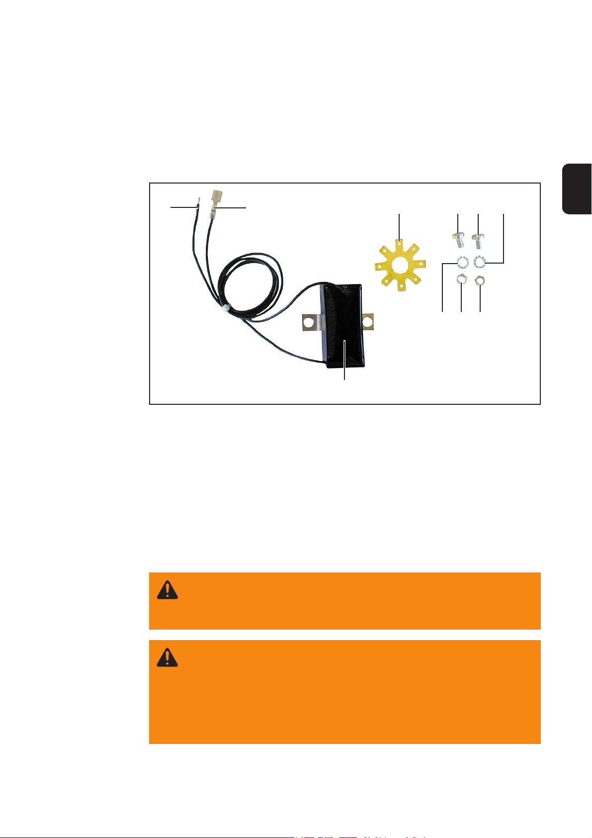
Abb.1 Einbauset Gasdüsen-Positionssuchen
Pos. Bezeichnung Stück
(1) Touch-Sensor 1
(2) Anschlusskabel Amphenolbuchse 1
(3) Anschlusskabel Buchsenstern 1
(4) Buchsenstern 1
(5) Linsenkopfschrauben 2
(6) Fächerscheiben 2
(7) Sechskantmuttern 2
(8) Kabelbinder (nicht abgebildet) 5
1
Page 4

Funktionsweise Das Einbauset Gasdüsen-Positionssuchen erweitert die Option Touch-Sensing um die
Möglichkeit einer Werkstück-Berührungserkennung mittels Gasdüse.
HINWEIS! Die Funktion Touch-Sensing wird ab Firmware OFFICIAL UST
V2.65.001 (Stromquelle) unterstützt.
Die Funktion Touch-Sensing steht standardmäßig zur Verfügung, wenn am LocalNet ein
Roboterinterface ROB 5000 oder ein Feldbus-Koppler für Roboteransteuerung angeschlossen ist.
Aktiviert wird Touch-Sensing über das digitale Eingangssignal Touch-Sensing des
Roboterinterfaces ROB 5000 oder des Feldbus-Kopplers.
In Verbindung mit der Option Gasdüsen-Positionssuchen kann mittels Signal TouchSensing eine Berührung der Gasdüse mit dem Werkstück festgestellt werden (Kurzschluss zwischen Werkstück und Gasdüse).
Wird das Signal Touch-Sensing gesetzt, zeigt das Bedienpanel der Stromquelle “touch”
an. An die Gasdüse wird eine Gleichspannung von ca. 30 V (Strom auf 3 A begrenzt)
angelegt.
Das Auftreten des Kurzschlusses wird über das Stromfluss-Signal (siehe Bedienungsanleitung ROB 4000 / 5000, Kapitel “Digitale Ausgangssignale”) an die Robotersteuerung
übermittelt.
Solange das Signal “Positionssuchen” gesetzt bleibt, kann kein Schweißvorgang stattfinden.
Die Option Gasdüsen-Positionssuchen beinhaltet ein RC-Glied, zur Verbindung der
Gasdüse mit der Schweißstrom-Leitung (+) .
2,2 µF / 160 V / 10 %
C
Schweißstromleitung (+)
C
4,7 µF / 160 V / 10 %
R
10 kOhm / 1 W / 10 %
Abb.2 RC-Glied zur Verbindung der Schweißstrom-Leitung mit der Gasdüse
Gasdüse
Der Einsatz eines RC-Gliedes ist erforderlich, um während des Schweißens, bei einer
möglichen Berührung der Gasdüse mit dem Werkstück
- Unzulässige Ströme über die Verbindung Gasdüse-Schweißstromleitung zu vermeiden
- Einer Beeinflussung des Schweißprozesses vorzubeugen
Im Falle der Berührungserkennung über die Gasdüse, fließt der Kurzschluss-Strom nur
ca. 4 ms, bis die Kondensatoren des RC-Gliedes aufgeladen sind. Für eine sichere
Berührungserkennung durch die Robotersteuerung, liegt das Stromfluss-Signal um 200
ms länger an als der Kurzschluss-Strom.
2
Page 5

Einbauset Gasdüsen-Positionssuchen bei VR 1500
einbauen
DE
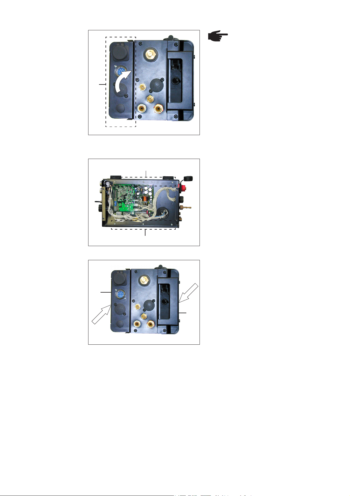
Vorbereitung
(Z)
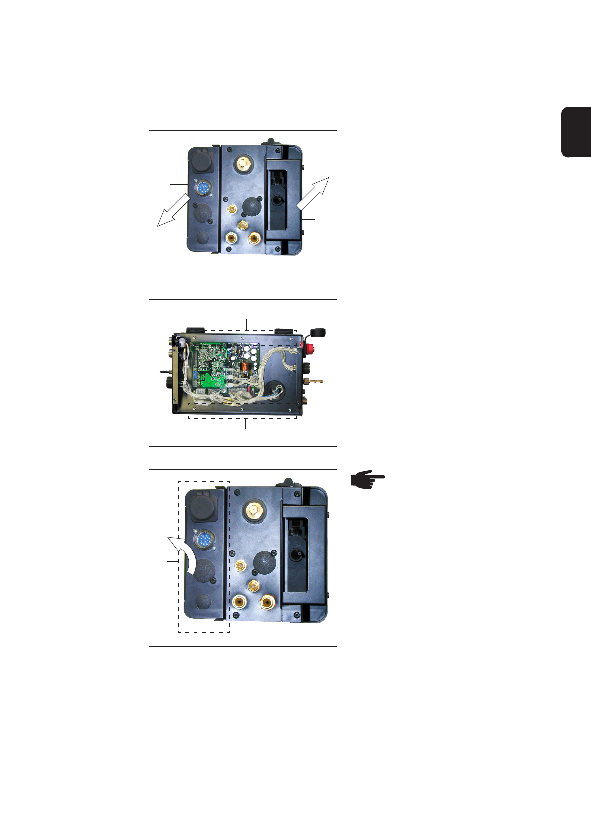
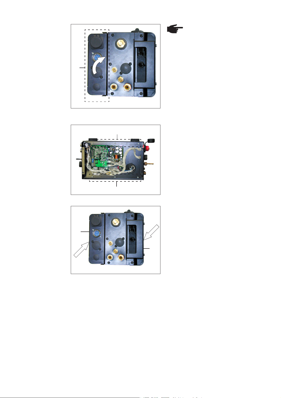
Abb.3 VR 1500: Seitenteile abmontieren
(A)
1. Seitenteil (Z) abmontieren
2. Drahtvorschubdeckel (ZA) öffnen
(ZA)
3. Steuergerät demontieren:
Sechs Schrauben Extrude-Tite (A)
lösen
(A)
Abb.4 VR 1500: 6 Schrauben lösen
(B)
Abb.5 VR 1500: Steuergerät zur Seite schwenken
HINWEIS! Beim Zur-SeiteSchwenken des Steuergeräts, die
Verbindungskabel weder knicken,
einklemmen, noch auf Zug
belasten.
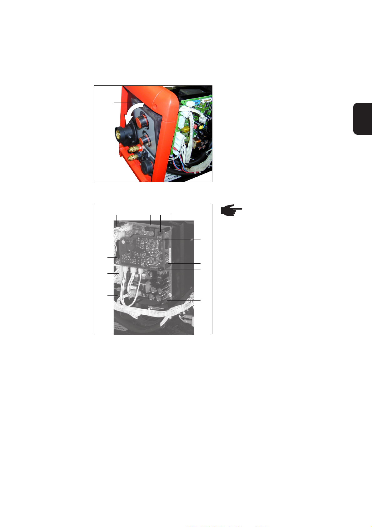
4. Steuergerät (B) zur Seite schwenken
3
Page 6

Buchsenstern
montieren
HINWEIS! Ist der Buchsenstern (4) bereits montiert, können die Arbeitsschritte
1. - 7. übergangen werden
(C)
(C)
(C)
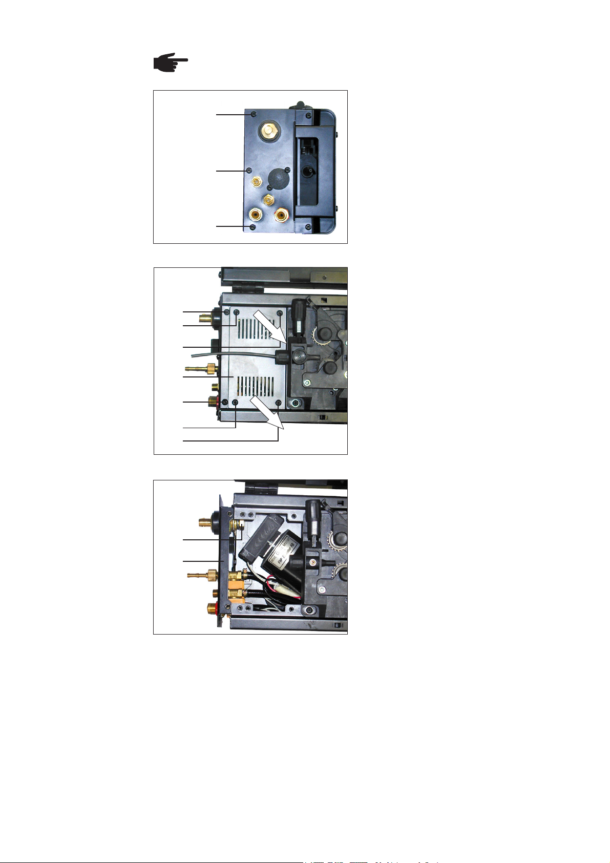
Abb.6 VR 1500: 3 Schrauben lösen
(D)
(E)
(E)
1. Drei Schrauben Extrude-Tite (C) lösen
2. Vier Schrauben Extrude-Tite (E) lösen
3. Abdeckung (F) abnehmen
4. Zwei Schrauben Extrude-Tite (D)
lösen
(F)
(D)
(E)
(E)
Abb.7 VR 1500: Abdeckplatte entfernen
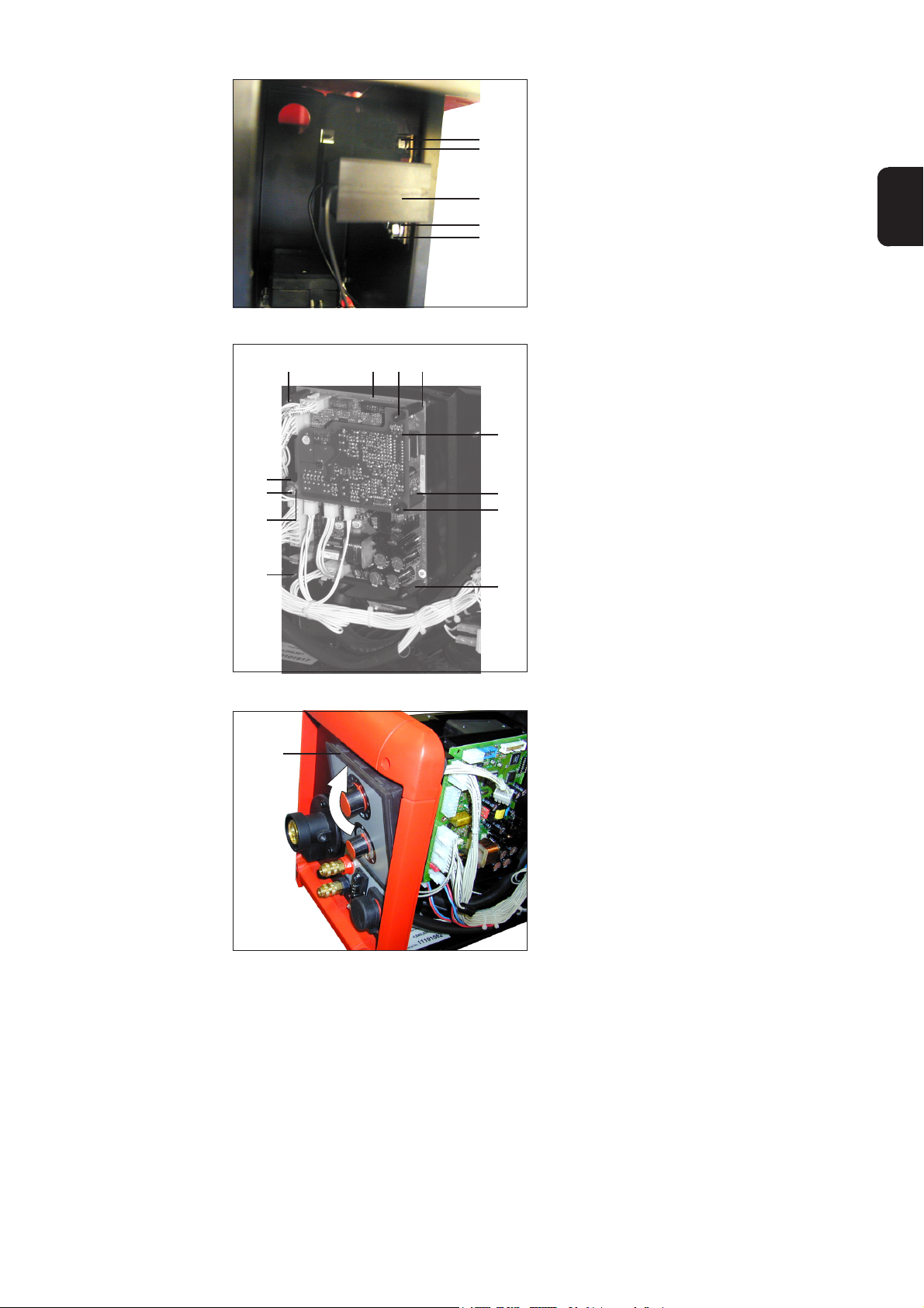
(I)
(G)
Abb.8 VR 1500: Abdeckung entfernen und
Anschlussplatte leicht anheben
5. Anschlussplatte (G) leicht anheben
6. Sechskantschraube (I) (SW 19) lösen
4
Page 7

Buchsenstern
montieren
(Fortsetzung)
(L)(K) (J)(I) (G)(4)
Abb.9 VR 1500: Buchsenstern am Stecker
Schweißpotential montieren
(C)
HINWEIS! Bei der Montage des
Buchsensternes (4) darauf
achten, dass das „Kabel
Schweißpotential“ (L) senkrecht
zur Anschlussplatte (G) verläuft
7. Buchsenstern (4) montieren
- Zwischen Kabelschuh (J) und
Messing-Beilagscheibe (K)
- Sechskantschraube (I) festschrau-
ben
8. Drei Schrauben Extrude-Tite (C)
festschrauben und Anschlussplatte
(G) montieren
DE
(C)
(C)
Abb.10 VR 1500: 3 Schrauben festschrauben
(D)
(E)
(E)
(F)
(D)
(E)
(E)
Abb.11 VR 1500: Abdeckplatte montieren
9. Zwei Schrauben Extrude-Tite (D)
festschrauben
10. Abdeckung (F) montieren:
Vier Schrauben Extrude-Tite (E)
festschrauben
5
Page 8

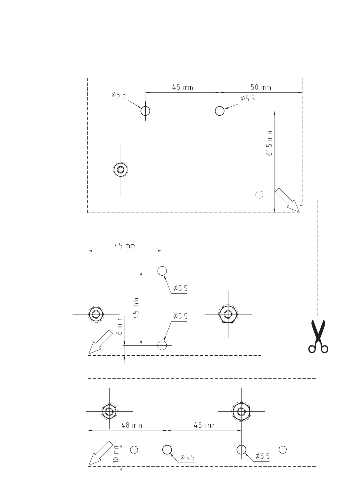
Montagebohrungen für Linsenkopfschrauben
anfertigen
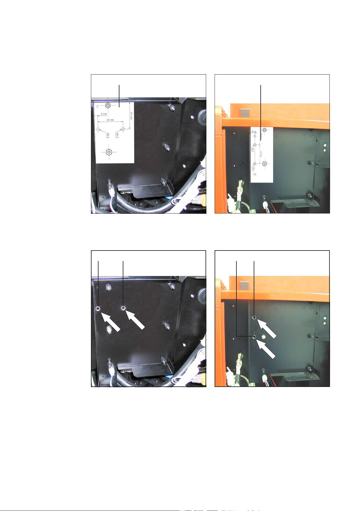
(B)
Abb.12 VR 1500: Position der Montagebohrungen
(B)
1. Nur falls im Steuergerät (B) keine
Bohrungen für die Linsenkopfschrauben (5) vorhanden sind, ...
... Montagebohrungen mittels beigehefteter Bohrschablone VR 1500 (ZB)
auf der Außenseite des Steuergerätes
(B) herstellen
2. Montagebohrungen entgraten
3. Bohrrückstände entfernen
Touch-Sensor
montieren und
anschließen
(ZB)
Abb.13 VR 1500: Bohrschablone am Steuergerät
(B) (1)(5) (5)
Abb.14 VR 1500: Touch-Sensor montieren
1. Touch-Sensor (1) im Steuergerät (B)
montieren:
mittels Linsenkopfschrauben (5)
und ...
6
Page 9

Touch-Sensor
montieren und
anschließen
(Fortsetzung)
(7) (6) (6)(7)
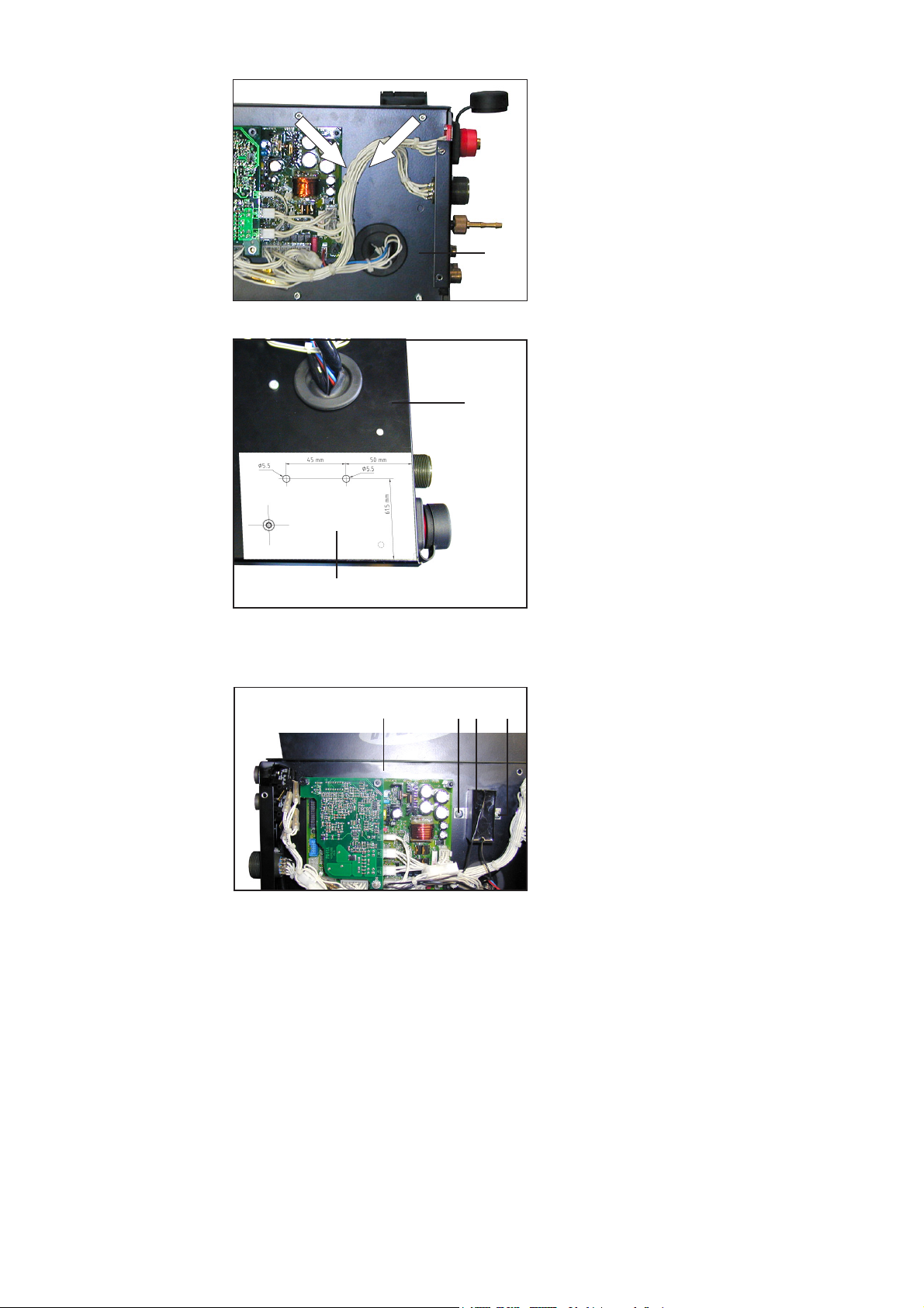
Abb.15 VR 1500: Touch-Sensor von außen
befestigen, Anschlusskabel Buchsenstern
durchlegen
(3)
(M)
...Fächerscheiben (6) und Sechskantmuttern (7)
DE
2. Anschlusskabel Buchsenstern (3) an
der Durchführung (M) des Steuergerätes durchlegen
(4) (3)
Abb.16 VR 1500: Anschlusskabel Buchsenstern am
Buchsenstern anschließen
(N)
(2)
3. “Anschlusskabel Buchsenstern” (3)
am Buchsenstern (4) anstecken
4. 14-polige „Amphenolbuchse Robacta“
(N) abmontieren
5. “Anschlusskabel Amphenolbuchse”
(2) an der 14-poligen „Amphenolbuchse Robacta“ (N) X10:J anlöten
6. 14-polige „Amphenolbuchse Robacta“
(N) montieren
7. Kabel mit Kabelbindern fixieren
Abb.17 VR 1500: Anschlusskabel Amphenolbuchse
an der Amphenolbuchse Robacta anlöten
7
Page 10

Abschließende
Tätigkeiten
(B)
(ZB)
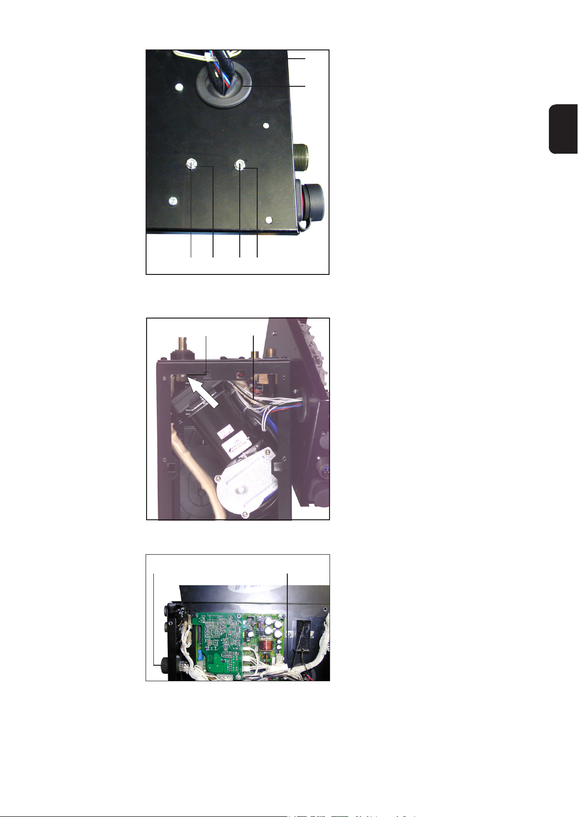
Abb.18 VR 1500: Steuergerät zum Drahtantrieb
schwenken
HINWEIS! Beim Schwenken des
Steuergeräts zum Drahtantrieb
die Verbindungskabel weder
knicken, einklemmen, noch auf
Zug belasten.
1. Steuergerät (B) zum Drahtantrieb
schwenken
(A)
(A)
Abb.19 VR 1500: 6 Schrauben befestigen
(Z)
2. Steuergerät montieren:
Sechs Schrauben Extrude-Tite (A)
befestigen
3. Seitenteil (Z) montieren
4. Drahtvorschubdeckel (ZA) schließen
(ZA)
Abb.20 VR 1500: Seitenteile montieren
8
Page 11

Einbauset Gasdüsen-Positionssuchen bei VR 4000 /
7000 einbauen
DE
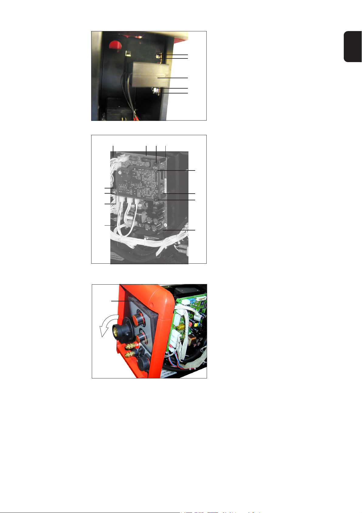
Vorbereitung
(R)
Abb.21 VR 4000: Bedienpanel abnehmen
(X)
(X)
(T)
(U)
(X)
(W)(V)
(X)
(S)
(X)
(V)
(X)
1. Rechtes Seitenteil öffnen
2. Bei Standardausführung:
8-poligen Molexstecker (O) von
Stecker X1 am Print SR41 abstecken
Bei Ausführung mit digitaler Anzeige:
10-poligen Flachbandstecker (nicht
abgebildet) vom Stecker X2 am SR41
abstecken
3. Bedienpanel (R) abnehmen
- An der Oberkante, vom Gehäuse-
inneren nach außen, herausdrükken
- Bedienpanel nach vorn abheben
HINWEIS! Bei der Demontage
der Prints PM41 und SR41, die
Kabel weder einklemmen, knicken, noch auf Zug belasten.
4. Falls vorhanden, Print PM41 (S)
demontieren:
- Sechskantmutter (T) lösen
- Sechskantmutter (T) mit Fächer-
scheibe (U) abnehmen
- Zwei Kunststoffdistanzen (V) lösen
- Print PM41 (S) abheben
5. Print SR41 (W) demontieren:
Sechs Distanzen (X) lösen
6. Print SR41 (W) abnehmen
Abb.22 VR 4000: Print PM 41 und SR 41 demontie-
ren
9
Page 12
Montagebohrungen für Linsenkopfschrauben
anfertigen
1. Nur falls keine Bohrungen für die Linsenkopfschrauben (5) vorhanden sind ...
Montagebohrungen mittels beigehefteter Bohrschablone VR 4000 (ZC) oder VR
7000 (ZD) herstellen
2. Montagebohrungen entgraten
3. Bohrrückstände entfernen
Touch-Sensor
montieren und
anschließen
(ZC)
Abb.23 VR 4000: Befestigungsbohrungen herstel-
len, falls nicht vorhanden
Abb.24 VR 7000: Befestigungsbohrungen herstel-
(Y) (Y) (Y)(Y)
(ZD)
len, falls nicht vorhanden
Abb.25 VR 4000: Befestigungsbohrungen Abb.26 VR 4000: Befestigungsbohrungen
1. Linsenkopfschrauben (5) an den Montagebohrungen (Y) ansetzen.
10
Page 13
Touch-Sensor
montieren und
anschließen
(Fortsetzung)
(7)
(6)
(1)
(6)
(7)
Abb.27 Touch-Sensor montieren, z.B. am VR 7000
2. Touch-Sensor (1) montieren:
- mittels Linsenkopfschrauben (5)
und
- Fächerscheiben (6) und Sechskantmuttern (7)
DE
(X)
(W)(V)
(X)
(S)
(X)
(T)
(U)
(X)
Abb.28 VR 4000: Print PM 41 und SR 41 montieren
(X)
(V)
(X)
(R)
3. Print SR41 (W) mit sechs Distanzen
(X) montieren
4. Falls vorhanden, Print PM41 (S)
montieren
- Mittels zwei Kunststoffdistanzen
(V), Sechskantmutter (T) und
Fächerscheibe (U)
5. Bedienpanel (R) montieren
- Senkrecht einsetzen
- An der Unterkante andrücken, bis
Arretierungen einrasten
- An der Oberkante andrücken, bis
Arretierungen einrasten
Abb.29 VR 4000: Bedienpanel montieren
6. Bei Standardausführung:
8-poligen Molexstecker (O) am
Stecker X1 am Print SR41 anstecken
Bei Ausführung mit digitaler Anzeige:
10-poligen Flachbandstecker (nicht
abgebildet) am Stecker X2 am Print
SR 41 anstecken
11
Page 14

Touch-Sensor
montieren und
anschließen
(Fortsetzung)
Tätigkeiten
(J)
(3)(4)
(K)
(I)
(I)(4)
Abb.30 VR 4000 / 7000: Touch-Sensor am Buch-
senstern anschließen
1. Rechtes Seitenteil montierenAbschließende
7. Sechskantschraube (I) (SW19) lösen
8. Buchsenstern (4) zwischen Kabelschuh (J) und Messing-Beilagscheibe
(K) montieren, Sechskantschraube (I)
(SW19) festschrauben
9. Anschlusskabel Buchsenstern (3) am
Buchsenstern (4) anstecken
10. 14-polige „Amphenolbuchse Robacta“
(N) (an der Gehäusevorderseite, nicht
abgebildet) abmontieren
11. “Anschlusskabel Amphenolbuchse”
(2) an der 14-poligen „Amphenolbuchse Robacta“ (N) X15:J anlöten
12. 14-polige „Amphenolbuchse Robacta“
(N) montieren
13. Kabel mit Kabelbindern fixieren
12
Page 15
WARNING! An electric shock can be fatal. Before opening up the machine:
- Shift the mains switch of the power source into the “O” position
- Unplug the power source from the mains
- Affix an easily readable and understandable warning sign to prevent
machine from being switched back on.
Upon opening up the machine discharge any live components, if available (e.g.
electrolytic capacitors).
WARNING! Work that is not carried out correctly can cause serious damage
and
injury. The actions described below may ONLY be carried out by skilled, trained
technicians! Observe and follow the “Safety rules” in the “Operating Instructions” manual for the power source.
General Remarks
General remarks
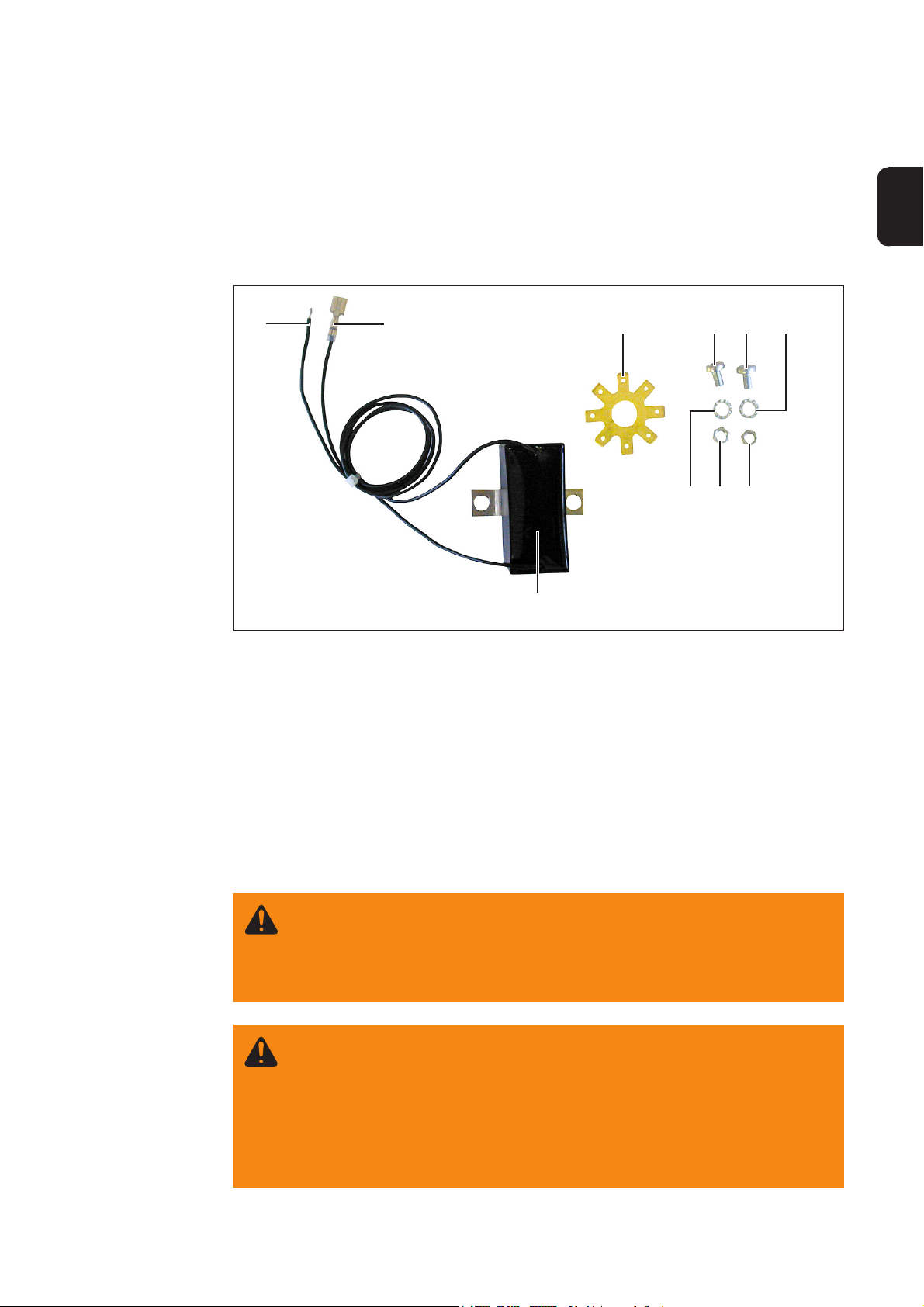
Components
Only use the gas-nozzle touch sensor installation kit in conjunction with welding torches
that have a connection from the gas nozzle to the 14-pole “Robacta Amphenol socket”,
Pin:J.
(2) (3)
(1)
(5)(4) (5) (6)
(7)(6)
(7)
EN
Safety
Fig.1 Gas-nozzle touch sensor installation kit
Item Article pcs.
(1) Touch sensor 1
(2) Cable connector for Amphenol socket 1
(3) Cable connector for socket star 1
(4) Socket star 1
(5) Cheese-head screws 2
(6) Serrated lock washers 2
(7) Hexagonal nuts 2
(8) Cable binders (not shown here) 5
1
Page 16
Mode of functioning
The gas-nozzle touch sensor installation kit extends the functionality of the touchsensing option by adding an option for touch-sensing the workpiece by means of the gas
nozzle.
NOTE! The touch-sensing function is supported from firmware OFFICIAL UST
V2.65.001 (power source) upwards.
The touch-sensing function is available as standard if there is a ROB 5000 robot interface and/or a field-bus coupler for robot control connected up to the LocalNet.
Touch-sensing is activated via the digital input signal “Touch-sensing” on the ROB 5000
robot interface or on the field-bus coupler.
Where the gas-nozzle touch-sensing option has been installed, the “Touch sensing”
signal tells the user when the gas nozzle is touching the workpiece (short circuit between
the workpiece and the gas nozzle).
When the touch-sensing signal is initialised, the word “touch” appears on the operating
panel of the power source. A DC voltage of approx. 30 V (current limited to3 A) is applied
to the gas nozzle.
The short circuit is reported to the robot control by the current-flow signal (see the
section of the ROB 4000 / 5000 Operating Instructions headed “Digital output signals”).
As long as the “Touch sensing” signal remains initialised, no welding can take place.
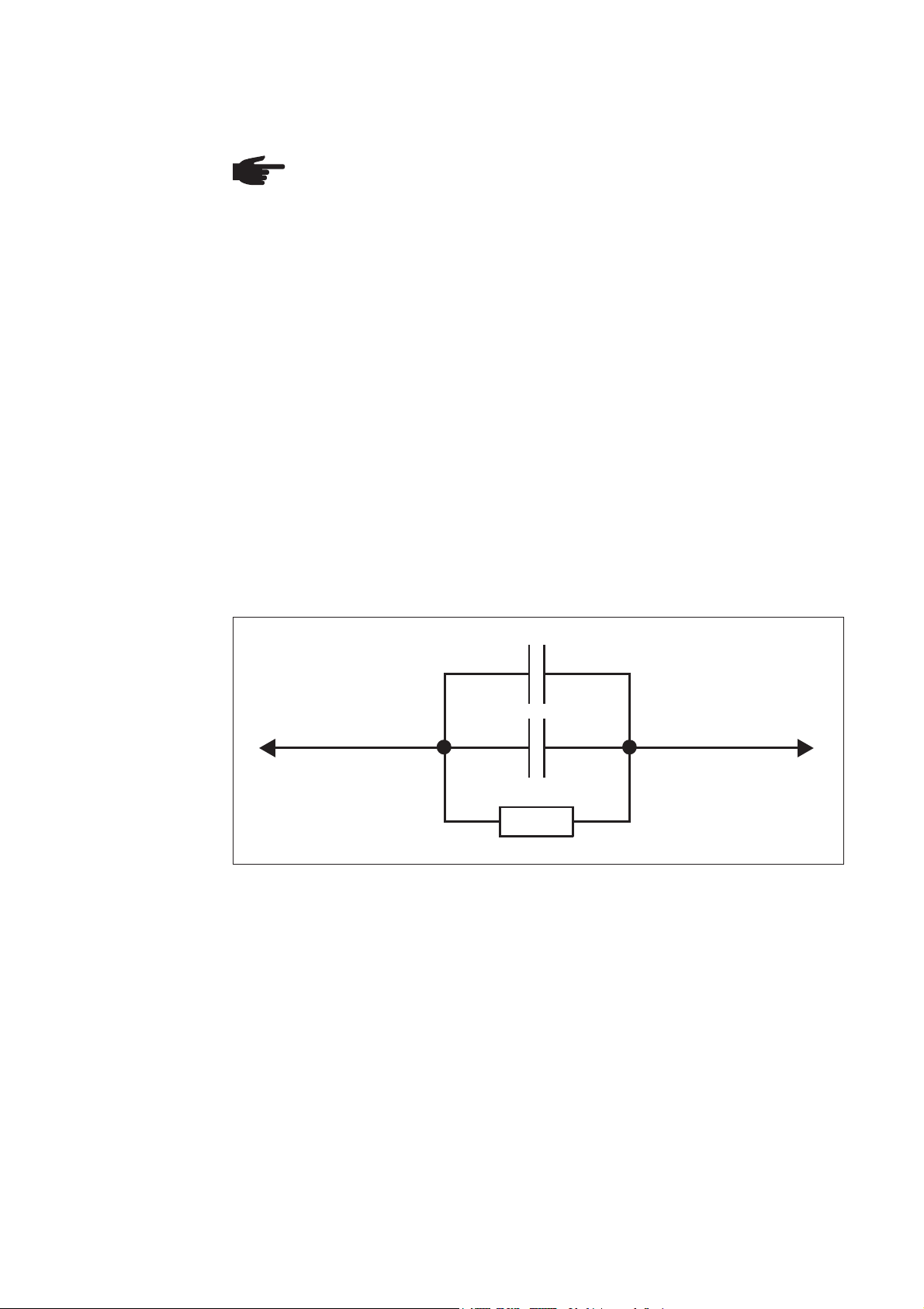
The gas-nozzle touch-sensing option includes a resistor-capacitor (RC) element for
linking the gas nozzle to the welding-current cable (+).
2,2 uF / 160 V / 10 %
C
Welding-current cable (+)
C
4,7 uF / 160 V / 10 %
R
10 kOhm / 1 W / 10 %
Fig.2 RC element for linking the welding-current cable to the gas nozzle
Gas nozzle
It is necessary to use a RC element in order to prevent the following problems occurring
during welding if the gas nozzle should happen to touch the workpiece:
- impermissible currents flowing across the link between the gas-nozzle and the
welding-current cable
- any influencing of the welding process
If touch-sensing occurs via the gas nozzle, the short circuit current only flows for approx.
4 ms, until the capacitors of the RC element are recharged. In order to ensure reliable
touch-sensing by the robot control, the current-flow signal is applied for 200 ms longer
than the short-circuit current.
2
Page 17
Installing the Gas-nozzle touch sensor installation kit
on the VR 1500
Preparations
(Z)
Fig.3 Take off the side panels
(A)
(ZA)
1. Take off the side panel (Z)
2. Open the wirefeeder cover (ZA)
3. Dismount the control unit:
Undo the six Extrude-Tite screws (A)
EN
(A)
Fig.4 VR 1500: Undo six screws
(B)
Fig.5 VR 1500: Swivel the control unit to one side
NOTE! When swivelling the
control unit to one side, do not
kink or pinch the connection
cables or subject them to tensile
strain.
4. Swivel the control unit (B) to one side
3
Page 18
Mounting the
socket star
NOTE! If the socket star (4) is already mounted, steps 1. - 7. can be omitted.
(C)
(C)
(C)
Fig.6 VR 1500: undo three Extrude-Tite screws
(D)
(E)
(E)
1. undo the three Extrude-Tite screws
(C)
2. undo the four Extrude-Tite screws (E)
3. take off the cover (F)
4. undo the two Extrude-Tite screws (D)
(F)
(D)
(E)
(E)
Fig.7 VR 1500: take off the cover
(I)
(G)
Fig.8 VR 1500: undo the hexagon-head screw
5. slightly raise the terminal plate (G)
6. undo the hexagon-head screw (I)
(width-across = 19)
4
Page 19

Mounting the
socket star
(continued)
(L)(K) (J)(I) (G)(4)
NOTE! When mounting the
socket star (4), make sure that
the “welding potential cable” (L)
runs perpendicular to the terminal
plate (G).
Fig.9 VR 1500: Mounting the socket star onto the
welding-potential-socket
(C)
(C)
(C)
7. Mount the socket star (4)
- between the cable lug (J) and the
brass washer (K)
- tighten the hexagon-head screw (I)
8. Tighten the three Extrude-Tite screws
(C) and mount the terminal plate (G)
EN
Fig.10 VR 1500: Tighten three screws
(D)
(E)
(E)
(F)
(D)
(E)
(E)
Fig.11 VR 1500: Mount the cover
9. tighten the two Extrude-Tite screws
(D)
10. Mount the cover (F):
tighten the four Extrude-Tite screws
(E)
5
Page 20
Drilling fixing
holes for cheesehead screws
Fig.12 VR 1500: Position of fixing holes
(B)
1. Only if there are no holes for the
cheese-head screws (5) in the control
unit (B):
(B)
Drill fixing-holes for the cheese-head
screws (5) using the attached drilling
template VR 1500 (ZB)
2. Deburr the fixing holes
3. Remove any drilling shavings etc.
Mounting and
connecting the
touch sensor
(ZB)
Fig.13 VR 1500: drilling template on control unit
(B) (1)(5) (5)
Fig.14 VR 1500: mounting the touch sensor
1. Mount the touch sensor (1) on the
control unit:
using the cheese-head screws (5)
and ...
6
Page 21
Mounting and
connecting the
touch sensor
(continued)
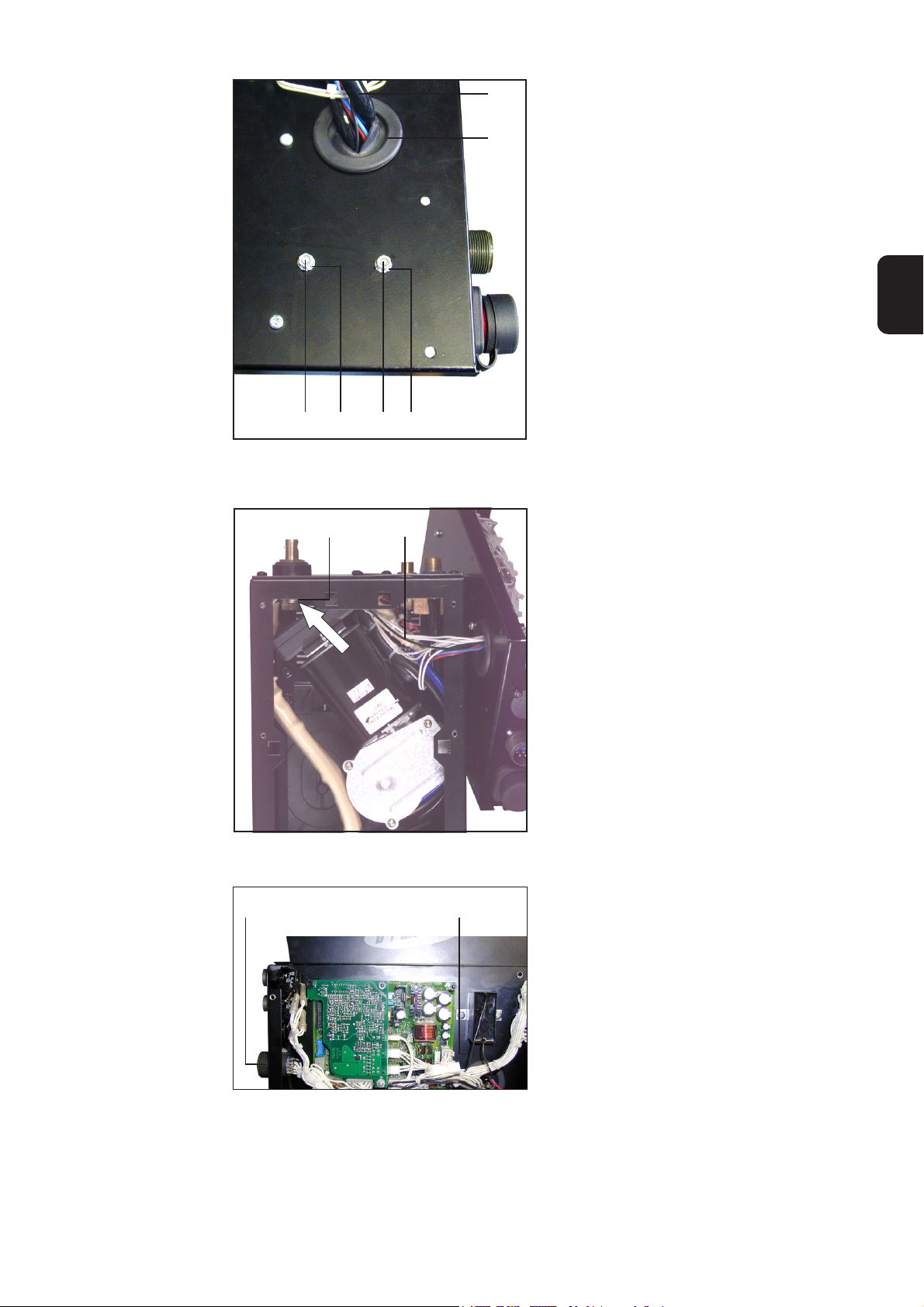
(3)
(M)
(7) (6) (6)(7)
Fig.15 VR 1500: mounting the touch sensor from
outside, passing the “Cable connector for
socket star” through the lead-through
...serrated washers (6) and hexagonal
nuts (7)
2. Pass the “Cable connector for socket
star” (3) through the lead-through (M)
on the control unit
EN
(4) (3)
Fig.16 VR 1500: Plug the “Cable connector for
socket star” onto the socket star
(N)
(2)
3. Plug the “Cable connector for socket
star” (3) onto the socket star (4)
4. Dismount the 14-pole “Robacta
Amphenol socket” (N)
5. Solder the “Cable connector for
Amphenol socket” (2) onto the 14pole “Robacta Amphenol socket” (N)
X10:J
6. Mount the 14-pole “Robacta Amphenol socket” (N)
7. Fix the cables with cable binders
Fig.17 VR 1500: Solder the “Cable connector for
Amphenol socket” onto the 14-pole “Robacta Amphenol socket”
7
Page 22
Finishing the job
NOTE! When mounting the
control unit, make sure that the
cables are not pinched, kinked or
subjected to tensile strain.
1. Swivel the control unit (B) to the wire
feeder
(B)
(ZB)
Fig.18 VR 1500: Swivel the control unit to the wire
feeder
(A)
(A)
Fig.19 VR 1500: tighten six screws
(Z)
2. Mount the control unit using six
Extrude-Tite screws (A)
3. Re-mount the side panel (Z)
4. Close the wirefeeder cover (ZA)
(ZA)
Fig.20 VR 1500: Re-mount side panels
8
Page 23

Installing the Gas-nozzle touch sensor installation kit
on the VR 4000 / VR 7000
Preparations
(R)
Fig.21 VR 4000: Take off the operating panel
(X)
(X)
(T)
(U)
(X)
(W)(V)
(X)
(S)
(X)
(V)
(X)
1. Open the right side panel
2. Standard version:
Unplug the 8-pole Molex plug (O)
from SR41 / X1
Version with digital display:
Unplug the 10-pole ribbon-cable plug
(not illustrated) from SR41 / X2
3. Take off the operating panel (R)
- hold the top edge of the panel and
push it out from the inside of the
housing towards the outside
- lift out the operating panel towards
the front
NOTE! When dismounting the
PM41 and SR41 boards, do not
pinch or kink the cables or
subject them to tensile strain.
4. If available, dismount board PM41 (S)
- Undo hexagonal nut (T)
- Take out hexagonal nut (T) and
serrated washer (U)
- Undo the two plastic spacers (V)
- Lift out board PM41 (S)
5. Dismount board SR41 (W):
Undo the six spacers (X)
6. Detach board SR41 (W)
EN
Fig.22 VR 4000: dismount board PM41 and SR 41
9
Page 24

Drilling fixing
holes for cheesehead screws
1. Only if there are no holes for the cheese-head screws (5):
Drill fixing-holes (Y) using the attached drilling template VR 4000 (ZC) or VR 7000
(ZD)
2. Deburr the fixing holes
3. Remove any drilling shavings etc.
Mounting and
connecting the
touch sensor
(ZC)
Fig.23 VR 4000: Drill fing-holes, if they are not
available
Fig.24 VR 7000: Drill fing-holes, if they are not
(Y) (Y) (Y)(Y)
(ZD)
available
Fig.25 VR 4000: fixing-holes Fig.26 VR 7000: fixing-holes
1. Insert the cheese-head screws (5) into the fixing-holes (Y)
10
Page 25
Mounting and
connecting the
touch sensor
(continued)
(7)
(6)
2. Mount the touch sensor (1):
- using the cheese-head screws (5)
and
- serrated washers (6) and hexagonal nuts (7)
(1)
(6)
(7)
Fig.27 Mounting the touch sensor, e.g. VR 7000
(X)
(W)(V)
(X)
(X)
(T)
(U)
(X)
(S)
(X)
(V)
(X)
EN
3. Mount board SR41 (W) with six
spacers (X)
4. Falls vorhanden, Print PM41 (S)
montieren
- Where applicable, mount board
PM41 (S), using 2 plastic spacers
(V) hexagonal nut (T) and serrated
washer (U)
Fig.28 VR 4000: mounting of PM 41 and SR 41
(R)
Fig.29 VR 4000: Mounting the operating panel
5. Mount the operating panel (R)
- insert vertically
- press on the bottom edge until the
it clicks into place
- press on the top edge until the it
clicks into place
6. Standard version:
Plug the 8-pole Molex plug (O) onto
SR41 / X1
Version with digital display:
Plug the 10-pole ribbon-cable plug
(not illustrated) onto SR 41 / X2
11
Page 26

Mounting and
connecting the
touch sensor
(continued)
(J)
(3)(4)
(K)
(I)
(I)(4)
Fig.30 VR 4000 / 7000: Connect the touch sensor
to the socket star
1. Re-mount the right side panelFinishing the job
7. Undo the hexagon-head screw (I)
(width-across = 19)
8. Mount the socket star (4) between the
cable lug (J) and the brass washer
(K). Tighten the hexagon-head screw
(I) (width-across = 19)
9. Plug the “Cable connector for socket
star” (3) onto the socket star (4)
10. Dismount the 14-pole “Robacta
Amphenol socket” (N) (on the front of
the housing - not shown)
11. “Solder the “Cable connector for
Amphenol socket” (2)onto the 14-pole
“Robacta Amphenol socket” (N) X15:J
12. Mount the 14-pole “Robacta Amphenol socket” (N)
13. Fix the cables with cable binders
12
Page 27
AVERTISSEMENT ! Un choc électrique peut être mortel. Avant d’ouvrir
l’appareil :
- Mettre le commutateur principal du générateur sur «O»
- Isoler le générateur du réseau
- Installer un écriteau lisible et compréhensible interdisant la remise en circuit
Après ouverture de l´appareil, décharger le cas échéant les composants à
charges électriques (p.ex. les condensateurs).
AVERTISSEMENT ! Des travaux mal effectués peuvent occasionner de graves
dommages matériels et corporels. Les opérations décrites ci-après doivent être
réalisées uniquement par le personnel qualifié de Fronius. Respectez les
consignes de sécurité du manuel d’utilisation de la source de courant.
Généralités
Généralités
Eléments de
construction
Les torches de soudage utilisées en liaison avec un kit «Détection de position Buse de
gaz» doivent être munies d‘un câble souple entre buse de gaz et point J du connecteur
mâle Amphenol «Robacta» à 14 points.
(2) (3)
(1)
(5)(4) (5) (6)
(7)(6)
(7)
FR
Sécurité
Fig.1 Kit d’installation «Détection de position Buse de gaz»
Pos. Article pcs.
(1) Détecteur de position 1
(2) Câble souple Connecteur Amphenol 1
(3) Câble souple Étoile à douille 1
(4) Étoile à douille 1
(5) Vis à tête goutte-de-suif 2
(6) Rondelles à denture concave 2
(7) Écrou hexagonal 2
(8) Cravate à câbles (sans illustration) 5
1
Page 28

Fonctionnement Suite à l’installation du kit «Détection de position Buse de gaz», la fonction «Détection de
position» permet de détecter également un contact entre pièce à travailler et buse de
gaz.
REMARQUE : La source de courant doit être dotée d’un logiciel OFFICIAL UST
V 2.65.001 ou plus pour que la fonction «Détection de position» soit disponible.
La fonction «Détection de position» est disponible en standard lorsqu’un interface
robotique ROB 5000 ou bien une carte coupleur, réalisant l’interface au bus de terrain,
est raccordée au LocalNet.
La Détection de position est activée par le biais du signal d’entrée numérique «Détection
de position» de l’interface robotique ROB 5000 ou bien de la carte coupleur du bus de
terrain.
Le kit optionnel «Détection de position Buse de gaz» permet de détecter, par le biais du
signal «Détection de position», un contact entre buse de gaz et pièce à travailler (courtcircuit entre pièce à travailler et buse de gaz).
Lorsque le signal «Détection de position» est actif, le message «touche» est affiché sur
le panneau de commande de la source de courant. Une tension continue d’environ 30 V
(courant limité à 3 A) est appliquée à la buse de gaz.
Un signal «conduction de courant» (voir Notice d’instructions ROB 4000 / 5000, chapitre
“Signaux de sortie numériques”) est transmis au contrôleur robotique lorsqu’il se produit
un court-circuit.
Tant que le signal «Détection de position» est actif, il n’est pas possible d’effectuer une
soudure.
Le kit «Détection de position Buse de gaz» comporte un circuit RC permettant de raccorder la buse de gaz au conducteur de courant de soudage (+).
2,2 µF / 160 V / 10 %
C
conducteur de courant de
soudage (+)
4,7 µF / 160 V / 10 %
10 kOhm / 1 W / 10 %
Fig.2 Circuit RC permettant de raccorder le conducteur de courant de soudage à la buse de gaz
C
R
buse de gaz
Le circuit RC est nécessaire pour assurer, dans le cas d‘un contact éventuel entre buse
de gaz et pièce à travailler, qu‘il n‘y ait pas de
- conduction de courant excessive entre buse de gaz et conducteur de courant de
soudage
- perturbation du processus de soudage
Dans le cas d‘un contact entre la buse de gaz et la pièce à souder, le courant de courtcircuit ne coule que pendant environ 4 ms, jusqu‘à la charge complète des condensateurs du circuit RC. Pour assurer la détection du contact par le contrôleur robotique, le
signal de conduction de courant est émis 200 ms plus longtemps que ne coule le courant de court-circuit.
2
Page 29

Installer le kit d’installation «Détection de position
Buse de gaz» dans VR 1500
Activités préparatrices
(Z)
(ZA)
Fig.3 VR 1500: Démonter joue et Ouvrir couvercle
(A)
1. Démonter joue (Z)
2. Ouvrir couvercle (ZA) du dévidoir-fil
FR
3. Démonter contrôleur:
Desserrer six vis Extrude-Tite (A)
(A)
Fig.4 VR 1500: Desserrer six vis
(B)
Fig.5 VR 1500: Pivoter contrôleur
REMARQUE : Lorsque vous
pivotez le contrôleur, veillez à ne
pas coincer, flamber ni mettre
sous traction les câbles de
raccord.
4. Pivoter contrôleur (B)
3
Page 30

Monter étoile à
douille
REMARQUE : Lorsque l‘étoile à douille (4) est déjà installée, les instructions (1.
- 7.) suivantes ne s‘appliquent pas.
1. Desserrer trois vis Extrude-Tite (C)
(C)
(C)
(C)
Fig.6 VR 1500: Desserrer trois vis
2. Desserrer quattre vis Extrude-Tite (E)
3. Oter plaque de recouvrement (F)
4. Desserrer deux vis Etrude-Tite (D)
(D)
(E)
(E)
(F)
(D)
(E)
(E)
Fig.7 VR 1500: Oter plaque de recouvrement
(I)
(G)
Fig.8 VR 1500: Légèrement soulever plaque de
connexion
5. Légèrement soulever plaque de
connexion (G)
6. Desserrer vis hexagonal (I) (SW 19)
4
Page 31

Monter étoile à
douille
(suite)
(L)(K) (J)(I) (G)(4)
Fig.9 VR 1500: Monter étoile à douille
(C)
(C)
REMARQUE : Lors du montage
de l‘étoile à douille (4), veiller à ce
que le câble „Potentiel de soudage“ (L) soit vertical par rapport à
la plaque de connexion (G).
7. Monter étoile à douille (4)
- entre cosse à câble (J) et rondelle
en laiton (K)
- serrer vis hexagonal (I)
FR
8. Serrer trois vis Extrude-Tite (C) et
monter plaque de connexion (G)
(C)
Fig.10 VR 1500: Serrer trois vis
(D)
(E)
(E)
(F)
(D)
(E)
(E)
Fig.11 VR 1500: Monter plaque de recouvrement
9. Serrer deux vis Extrude-Tite (D)
10. Monter plaque de recouvrement (F):
serrer quatre vis Extrude-Tite (E)
5
Page 32

Aléser trous de
fixation pour les
vis à tête gouttede-suif
Fig.12 VR 1500: Position des trous de fixation
(B)
1. Marche à suivre pour aléser, le cas
échéant, les trous de fixation (5) de
l‘appareil de commande (B) ...
(B)
Aléser trous de fixation sur la face
externe de l’appareil de commande
(B) en se servant du gabarit d‘alésage
VR 1500 (ZB) ci-joint
2. Ebarber les trous de fixation
3. Enlever copeaux de métal
Monter détecteur
de position
(ZB)
Fig.13 VR 1500: Gabarit d‘alésage sur l’appareil de
la commande
(B) (1)(5) (5)
Fig.14 VR 1500: Monter détecteur de position
1. Monter détecteur de position (1):
en se servant des vis à tête gouttede-suif (5) ainsi que des
et ...
6
Page 33
Monter détecteur
de position
(suite)
(3)
(M)
(7) (6) (6)(7)
Fig.15 VR 1500: Monter le détecteur de position de
l’extérieure, conduire le cable de raccord
étoile à douille à travers la traversée
... rondelles à denture concave (6) et
des écrous hexagonaux (7)
2. Conduire “Câble de raccord Etoile à
douille” (3) à travers la:
traversée (M) de l‘appareil de commande
FR
(4) (3)
Fig.16 VR 1500: Raccorder “Câble de raccord
Etoile à douille” à l‘étoile à douille
(N)
(2)
3. Raccorder “Câble de raccord Etoile à
douille” (3) à l‘étoile à douille(4)
4. Démonter „Connecteur femelle
Amphenol Robacta“ à 14 points (N)
5. Braser “Câble de raccord Connecteur
femelle Amphenol” (2) au „Connecteur femelle Amphenol Robacta“ à
14 points (N) X10:J
6. Monter „Connecteur femelle Amphenol Robacta“ à 14 points (N)
7. Fixer câbles aux cravates à câbles
Fig.17 VR 1500: Braser “Câble de raccord
Connecteur femelle Amphenol” (2) au
„Connecteur femelle Amphenol Robacta“
7
Page 34
Activités finales
(B)
(ZB)
Fig.18 VR 1500: Pivoter l’appareil de commande
en direction du dévidoir-fil
REMARQUE : Lorsque vous
pivotez l‘appareil de commande
en direction du dévidoir-fil, veillez
à ne pas coincer, flamber ni
mettre sous traction les câbles.
1. Pivotez l‘appareil de commande (B)
en direction du dévidoir-fil
(A)
(A)
Fig.19 VR 1500: Serrer six vis
(Z)
2. Monter appareil de commande:
Serrer six vis Extrude-Tite (A)
3. Monter joue (Z)
4. Fermer couvercle du dévidoir-fil (ZA)
(ZA)
Fig.20 VR 1500: Monter joue et couvercle du
dévidoir-fil
8
Page 35
Installer le kit d’installation «Détection de position
Buse de gaz» dans VR 4000 / 7000
Activités préparatrices
(R)
Fig.21 VR 4000: Oter panneau de commande de la
manière suivante
(X)
(X)
(T)
(U)
(X)
Fig.22 VR 4000: Démonter plaquette SR41 et PM
41
(W)(V)
(X)
(S)
(X)
(V)
(X)
1. Ouvrir joue droite
2. Modèle standard:
retirer connecteur Molex à 8 points
(O) du SR41 / X1
FR
Modèle avec afficheur numérique:
retirer embase à 10 points pour câble
plat (sans illustration) du SR41 / X2
3. Oter panneau de commande (R) de la
manière suivante
- Au bord supérieur, pousser de
l‘intérieur vers l‘extérieur.
- Retirer panneau de commande
REMARQUE : Lorsque vous
démontez les plaquettes à
circuits imprimés PM41 et SR41,
veillez à ne pas coincer, flamber
ni mettre sous traction les câbles
de raccord.
4. Le cas échéant, démonter plaquette
PM41 (S):
- desserrer écrou hexagonal (T)
- enlever écrou hexagonal (T) et
rondelle à denture concave (U)
- desserrer deux pièces
d‘écartement (V)
- ôter plaquette PM41 (S)
5. Démonter plaquette SR41 (W):
desserrer dix pièces d‘écartement (X)
6. Oter plaquette SR41 (W)
9
Page 36

Aléser trous de
fixation pour les
vis à tête gouttede-suif
1. Sinon les trous de fixation pour les vis à tête goutte-de-suif (5) n’existent pas,
marche à suivre ...
Aléser trous de fixation (Y) en se servant du gabarit d‘alésage VR 4000 (ZC) ou VR
7000 (ZD) respectivement
2. Ebarber les trous de fixation
3. Enlever copeaux de métal
Monter détecteur
de position
(ZC)
Fig.23 VR 4000: Aléser trous de fixation (sinon les
trous n’existent pas)
Fig.24 VR 7000: Aléser trous de fixation (sinon les
(Y) (Y) (Y)(Y)
(ZD)
trous n’existent pas)
Fig.25 VR 4000: trous de fixation Fig.26 VR 4000: trous de fixation
1. Introduire vis à tête goutte-de-suif (5) dans les alésages (Y) du côté
10
Page 37

Monter détecteur
de position
(suite)
(7)
(6)
(1)
(6)
(7)
Fig.27 Monter détecteur de position, p.ex. sur le
VR 7000
2. Monter détecteur de position (1):
- en se servant des vis à tête
goutte-de-suif (5) ainsi que des
- rondelles à denture concave (6) et
des écrous hexagonaux (7)
FR
(X)
(W)(V)
(X)
(X)
(T)
(U)
(X)
Fig.28 VR 4000: Monter SR41 et PM41
(R)
(S)
(X)
(V)
(X)
3. Monter SR41 (W) en se servant de
six pièces d‘écartement (X)
4. Le cas échéant, monter plaquette
PM41 (S)
- en se servant de deux pièces
d‘écartement (V), écrou hexagonal
(T) et rondelle à denture concave
(U)
5. Monter panneau de commande (R)
- insérer verticalement
- appuyer sur le bord inférieur
jusqu‘à ce qu‘il s‘encliquette
- appuyer sur le bord supérieur
jusqu‘à ce qu‘il s‘encliquette
Fig.29 VR 4000: Monter panneau de commande
11
6. Modèle standard:
ficher connecteur Molex à 8 points
(O) dans SR41 / X1
Modèle avec afficheur numérique:
ficher embase à 10 points pour câble
plat (sans illustration) dans SR41 /
X2
Page 38

Monter détecteur
de position
(suite)
(J)
(3)(4)
(K)
(I)
(I)(4)
Fig.30 VR 4000 / 7000: Raccorder le détecteur de
position sur l’étoile à douille
1. Monter joue droiteActivités finales
7. Desserrer vis hexagonal (I) (SW19)
8. Monter étoile à douille (4) entre cosse
à câble (J) et rondelle en laiton (K),
serrer vis hexagonal (I) (SW 19)
9. Raccorder “Câble de raccord Etoile à
douille” (3) à l‘étoile à douille (4)
10. Démonter „Connecteur femelle
Amphenol Robacta“ à 14 points(N)
(sans illustration)
11. Braser “Câble de raccord Connecteur
femelle Amphenol” (2) au „Connecteur femelle Amphenol Robacta“ à
14 points (N) X15:J
12. Monter „Connecteur femelle Amphenol Robacta“ à 14 points (N)
13. Fixer câbles aux cravates à câbles
12
Page 39
Bohrschablone / Drilling template / Gabarit de per
Çage
VR 1500
VR 4000
VR 7000
Page 40

Page 41

FRONIUS INTERNATIONAL GMBH
Froniusplatz 1, A-4600 Wels, Austria
Tel: +43 (0)7242 241-0, Fax: +43 (0)7242 241-3940
E-Mail: sales@fronius.com
www.fronius.com
Under http://www.fronius.com/addresses you will find all addresses
www.fronius.com/addresses
of our Sales & service partners and Locations.
ud_fr_st_so_00082 012011
 Loading...