

Page 1

/ Battery Charging Systems / Welding Technology / Solar Electronics
E-Set Gasregler
Gas controller installation kit
Einbauanleitung
Ersatzteilliste
DEEN
Einbauset
Installation Instructions
Spare Parts List
Installation kit
42,0410,1560 002-28032012
Page 2

Page 3

Inhaltsverzeichnis
Allgemeines................................................................................................................................................... 2
Gerätekonzept.......................................................................................................................................... 2
Lieferumfang ............................................................................................................................................ 2
Systemvorraussetzungen ......................................................................................................................... 2
Bedienelemente und Anschlüsse .................................................................................................................. 3
Sicherheit ................................................................................................................................................. 3
Steuergerät Vorderseite ........................................................................................................................... 3
Steuergerät Rückseite.............................................................................................................................. 4
Systemkomponenten und Verbindungen ...................................................................................................... 5
Übersicht Gesamtsystem ......................................................................................................................... 5
Installation Verbindungs-Schlauchpaket ....................................................................................................... 8
Sicherheit ................................................................................................................................................. 8
Verbindungsschlauchpaket an das Steuergerät montieren ...................................................................... 8
Stromkabel montieren .............................................................................................................................. 9
Schläuche und Leitungen vom Verbindungs-Schlauchpaket anschließen ............................................. 10
Deckel und Seitenteile montieren .......................................................................................................... 10
PlasmaModule 10: Einbau Gasmagnetventil .............................................................................................. 12
Sicherheit ............................................................................................................................................... 12
Systemvorraussetzungen ....................................................................................................................... 12
Vorbereitung........................................................................................................................................... 12
Proportional-Magnetventil demontieren ................................................................................................. 12
Gas-Magnetventil montieren und anschließen ....................................................................................... 13
Digital-Gas 10 deaktivieren .................................................................................................................... 14
DE
Drehzapfen-Aufnahme vorbereiten ............................................................................................................. 15
Montagebleche auf Drehzapfen-Aufnahme montieren........................................................................... 15
Steuergerät auf Drehzapfen-Aufnahme montieren...................................................................................... 15
Steuergerät auf Aufnahme montieren .................................................................................................... 15
PlasmaModule mit Steuergerät verbinden .................................................................................................. 16
Sicherheit ............................................................................................................................................... 16
PlasmaModule mit Steuergerät verbinden ............................................................................................. 16
Pflege, Wartung und Entsorgung ................................................................................................................ 17
Allgemeines ........................................................................................................................................... 17
Alle 6 Monate ......................................................................................................................................... 17
Entsorgung ............................................................................................................................................. 17
Technische Daten........................................................................................................................................ 17
Steuergerät „E-Set Gasregler“ ............................................................................................................... 17
Ersatzteilübersicht ....................................................................................................................................... 18
Steuergerät E-Set Gasregler ....................................................................................................................... 21
PlasmaModule 10 ....................................................................................................................................... 22
1
Page 4

Allgemeines
Gerätekonzept
Systemvorraussetzungen
Lieferumfang
Das „Einbauset Gasregler“ ist eine Systemerweiterung für bestehende Plasmasysteme
mit integriertem PlasmaModule 10. Das Steuergerät ermöglicht die Einstellung der
Plasmagas-Durchflussmenge während oder außerhalb des Schweißprozesses.
Die Dosierung erfolgt durch den frontseitig eingebauten digitalen Gasregler „Roboflow
DFC“. Der Gasregler ist mit einer beleuchteten Digitalanzeige ausgestattet und ermöglicht somit die laufende Kontrolle der aktuellen Plasmagas-Durchflussmenge. Durch die
Einbindung dieser Erweiterung ist es möglich das Plasmagas unabhängig vom Schutzgas zu dosieren.
Der Betrieb des „Einbauset Gasregler“ ist ab folgender Konfiguration des PlasmaModule
10 möglich:
- erforderliche Firmware: OFFICIAL UST V4.26.36
- Print UST-2C (4,070,960)
(1)
(3)
(2)
(5)
(4)
(6)
(8)
Lieferumfang E-Set Gasregler
(1) Steuergerät
(2) Anschluss-Stecker „Ext. Steuerung“
(3) 7 Schrauben Extrude-Tite M5 x 16
(4) Sechskantmutter
(5) O-Ring
(6) Magnetventil
(9)
(10)
(7)
(11)
(12)
(7) Schlauchklemme
(8) 15 Kabelbinder
(9) 6 Schrauben Extrude-Tite M5 x 16
(10) 2 Montagebleche
(11) Verbindungskabel LocalNet
(12) Verbindungs-Gasschlauch
2
Page 5

WARNUNG! Fehlbedienung kann schwerwiegende Personen- und Sachschäden verursachen. Beschriebene Funktionen erst anwenden, wenn folgende
Dokumente vollständig gelesen und verstanden wurden:
- diese Bedienungsanleitung
- sämtliche Bedienungsanleitungen der Systemkomponenten, insbesondere
Sicherheitsvorschriften
Bedienelemente und Anschlüsse
Sicherheit
Steuergerät
Vorderseite
(1)
DE
(6)
(5)
(4)
Vorderansicht Steuergerät
Nr. Funktion
(1) Anschluss Brennersteuerung
... zum Anschließen des Steuerkabels vom Plasma-Schweißbrenner PTW-1500.
(2) Digitaler Gasregler
... zum Dosieren der Plasmagas-Durchflussmenge in l / min. Detaillierte Informationen zum digitalen Gasregler Roboflow finden Sie in der Bedienungsanleitung
„Roboflow DFC“.
(3) Anschluss Wasserrücklauf (rote Farbmarkierung)
... zum Anschließen des Wasserrücklauf-Schlauches vom Plasma-Schweißbrenner.
(4) Anschluss Wasservorlauf (schwarze Farbmarkierung)
... zum Anschließen des Wasservorlauf-Schlauches vom Plasma-Schweißbrenner.
(5) Durchführung Stromkabel
... zum Positionieren der Strombuchse (mit Bajonettverschluss) des Verbindungsschlauchpaketes.
(6) Anschluss externe Steuerung
... zum Anschließen einer externen übergeordneten Steuerung.
3
(2)
(3)
Page 6

Steuergerät
Rückseite
(4)
(3)
Rückansicht Steuergerät
(5)
(6)
(1)
(2)
Nr. Funktion
(1) Durchführung Schlauchpaket
... zum Einfädeln des Verbindungsschlauchpakets der WIG-Stromquelle.
... zum Montieren der Zugenlastung des Verbindungsschlauchpaketes der WIGStromquelle
(2) Anschluss LocalNet
... zum Anschließen des Verbindungskabels zum PlasmaModule 10.
(3) Anschluss Plasmagas
... zum Anschließen der Plasmagas-Versorgung (Gasflasche). Der maximale Eingangsdruck beträgt 9 bar (130 psi).
(4) Druckminderventil
... zum Anschließen an „Eingang Plasmagas“ des Steuergerätes.
HINWEIS! Gesundheitsgefährdung durch farb- und geruchloses Schutzgas.
Nach Schweißende besteht die Gefahr eines nicht vollständig schließenden
Stellventils. Es könnte unbemerkt farb- und geruchloses Schutzgas entweichen. Die Einstellschraube am Druckminderventil keinesfalls verstellen.
Wird die Einstellschraube verstellt, übernimmt Fronius keine Haftung für
daraus resultierende Folgeschäden. Den maximalen Eingangsdruck der
Schutzgas-Versorgung nicht überschreiten. Der maximale Eingangsdruck
beträgt 9 bar (130 psi).
(5) Anschluss Eingang Plasmagas
... zum Anschließen des Druckminderventiles (4).
(6) Anschlus Ausgang Plasmagas
... zum Anschließen des Verbindungs-Gasschlauches zum PlasmaModule 10.
4
Page 7

Systemkomponenten und Verbindungen
Übersicht Gesamtsystem
PlasmaModule 10
D1
D2
C6
DE
VerbindungsSchlauchpaket
Externe
Steuerung
C1
A5
A2
A3
A4
Steuergerät
C2
C3
C4
C5
MW/ TT
2500/ 3000 Job
PTW 1500
A1
B3
B1
B2
FK 2500 MV-FC
5
Page 8

Übersicht Gesamtsystem
(Fortsetzung)
Plasmagas
C7
Netzversorgung
(230 V)
C8
Schutzgas
Netzversorgung
(3 x 400 V)
6
Page 9

Übersicht Gesamtsystem
(Fortsetzung)
Pos.
A1
Anschluss-Symbol/
-Komponente
Komponente Anschluss-Symbol/ -
Komponente
Massekabel
Masseklemme
DE
A2
A3
A4
A5
B1
B2
B3
Tuchelstecker
Verbindungskabel „LocalNet“
(im Schlauchpaket)
Verbindungskabel „Brennersteuerung“
(im Schlauchpaket)
Stromkabel „Schweißbrenner“ (im
Schlauchpaket)
Verbindungskabel „externe Steuerung“
Schlauch für „Wasservorlauf“ - blaue Farbmarkierung
(im Schlauchpaket)
Schlauch für „Wasserrücklauf“ - rote Farbmarkierung
(im Schlauchpaket)
Kabelbaum mit Molex-Steckverbindung
---
---
---
---
---
---
------
C1
C2
C3
C4
C5
C6
C7
C8
Tuchelstecker
Tuchelstecker
---
Verbindungskabel „externe Steuerung“
Schlauch für „Wasserrücklauf“ - rote Farbmarkierung
(im Brenner-Schlauchpaket)
Schlauch für „Wasservorlauf“ schwarze Farbmarkierung
(im Brenner-Schlauchpaket)
Verbindungskabel „Brennersteuerung“
(im Brenner-Schlauchpaket)
Stromkabel „Schweißbrenner“
(im Brenner-Schlauchpaket)
Kabelbaum mit Molex-Steckverbindung
Kabelbaum mit Molex-Steckverbindung
Verbindungskabel „LocalNet“
---
Plasmabrenner
PTW 1500
Plasmabrenner
PTW 1500
Plasmabrenner
PTW 1500
Plasmabrenner
PTW 1500
---
D1
D2
Stromkabel „Pilotstrom - “
(im Brenner-Schlauchpaket)
Stromkabel „Pilotstrom +“
(im Brenner-Schlauchpaket)
7
Plasmabrenner
PTW 1500
Plasmabrenner
PTW 1500
Page 10

Installation Verbindungs-Schlauchpaket
WARNUNG! Ein elektrischer Schlag kann tödlich sein. Sind WIG-Stromquelle
oder PlasmaModule 10 während der Installation am Netz angesteckt, besteht
die Gefahr schwerwiegender Personen- und Sachschäden. Sämtliche Arbeiten
nur Durchführen, wenn:
- der Netzschalter von WIG-Stromquelle und PlasmaModule 10 in Stellung
„O“ geschaltet ist
- WIG-Stromquelle und PlasmaModule 10 vom Netz getrennt sind
Sicherheit
Verbindungsschlauchpaket an
das Steuergerät
montieren
ca. 450 mm
Verbindungsschlauchpaket einfädeln
Zugentlastung
Schraube
1. Verbindungsschlauchpaket gemäß
folgender Reihenfolge durch die
Durchführung Schlauchpaket des
Steuergerätes einfädeln:
a) Stromkabel
b) Steuerleitung
c) Wasserleitungen
Wichtig! Das Stromkabel muss mindestens 450 mm aus dem Schutzschlauch
ragen!
2. Nur wenn das Stromkabel weniger als
450 mm aus dem Schutzschlauch
ragt:
- Schraube an der Zugentlastung
des Verbindungs-Schlauchpaketes
lockern
- Zugentlastung und Schutzschlauch
zurück schieben, bis das Stromkabel mindestens 450 mm aus dem
Schutzschlauch ragt
- Schraube an der Zugentlastung
wieder festziehen
Zugentlastung und Schutzschlauch nach hinten
schieben
3. Stromkabel durch die gelöste Halteschelle in die „Durchführung Stromkabel“ ziehen und im Gehäuse einrichten
Stromkabel durch Halteschelle ziehen
8
Page 11

Verbindungsschlauchpaket an
das Steuergerät
montieren
(Fortsetzung)
Zugentlastung montieren
4. Zugentlastung vom VerbindungsSchlauchpaket mit 3 Schrauben
Extrude-Tite M5 x 16 mm an das
Steuergerät montieren
DE
Stromkabel
montieren
10 mm
Stromkabel-Anschluss einrichten
1. Stromkabel-Anschluss so einrichten
dass dieser ca. 10 mm aus dem
Steuergerät ragt. Die Kontakt-Kerbe
für den Bajonett-Anschluss muss
nach unten gedreht sein.
2. 4 Innensechskant-Schrauben an der
Befestigungsschelle festziehen.
Diese sind mit Stoppmuttern an der
Gehäuseunterseite verbunden.
Stromkabel mittels Befestigungsschelle fixieren
9
Page 12

Schläuche und
Leitungen vom
VerbindungsSchlauchpaket
anschließen
1. Wasserleitungen vom VerbindungsSchlauchpaket entsprechend den
Farbmarkierungen mit den Wasserleitungen des Steuergerät verbinden.
Wasserschläuche verbinden
2. Steuerkabel vom VerbindungsSchlauchpaket mit Verlängerung
Brennersteuerung verbinden und
mittels Metallbügel verriegeln
Deckel und
Seitenteile montieren
Steuerkabel anschließen
3. Leitungen wie im Bild dargestellt
verlegen und mittels Kabelbinder
fixieren
Leitungen verlegen und fixieren
1. Molex-Steckverbinder durch die
Deckelöffnung ziehen
2. Gehäusedeckel auflegen und mit 4
Schrauben Extrude-Tite M5 x 10 mm
montieren
Deckel montieren
10
Page 13

Deckel und
Seitenteile montieren
(Fortsetzung)
Seitenteile montieren
3. Beide Seitenteile einhängen und mit
jeweils 3 Schrauben Extrude-Tite M5
x 10 mm montieren
DE
11
Page 14
PlasmaModule 10: Einbau Gasmagnetventil
WARNUNG! Fehlerhaft durchgeführte Arbeiten können schwerwiegende
Personen- und Sachschäden verursachen. Nachfolgend beschriebene Tätigkeiten dürfen nur von geschultem Fachpersonal durchgeführt werden! Beachten Sie
die Sicherheitsvorschriften in der Bedienungsanleitung des PlasmaModule 10.
WARNUNG! Ein elektrischer Schlag kann tödlich sein. Vor Öffnen des Gerätes:
- Netzschalter des PlasmaModule 10 in Stellung „O“ schalten
- PlasmaModule 10 vom Netz trennen
Sicherheit
Systemvorraussetzungen
Vorbereitung
ProportionalMagnetventil
demontieren
Der Betrieb des „Einbauset Gasregler“ ist ab folgender Konfiguration des PlasmaModule
10 möglich:
- erforderliche Firmware: OFFICIAL UST V4.26.36
- Print UST-2C (4,070,960)
1. Netzschalter des PlasmaModule 10 in Stellung „0“ schalten
2. PlasmaModule 10 vom Netz trennen
3. Rechtes Seitenteil entfernen
1. Anschluss-Kabel „Regelventil 1“ und
„Regelventil 2“ vom Gas-Magnetventil
abziehen
2. Schlauchklemme mittels Zange
öffnen und Gasschlauch vom Magnetventil abziehen
Anschlusskabel und Schlauch abziehen
3. Sechskantmutter mittels Gabelschlüssel Größe 17 lösen und Magnetventil
entfernen
Sechskantmutter lösen
12
Page 15

Gas-Magnetventil
montieren und
anschließen
1. O-Ring aufschieben und Magnetventil
in gleicher Lage platzieren
DE
O-Ring
Magnetventil platzieren
2. Sechskantmutter aufschrauben und
mittels Gabelschlüssel Größe 17
festziehen
Sechskantmutter aufschrauben und festziehen
Gasschlauch aufschieben und fixieren
3. Gasschlauch mit Schlauchklemme
auf Stecknippel aufschieben und mit
Zange festziehen
Anschlusskabel lösen Anschlusskabel anstecken
4. Anschlusskabel „Gasmagnetventil -Y1:A1“ und „Gasmagnetventil-Y1:A2“ vom
Kabelbaum lösen und am Magnetventil: A1, A2 anschließen
13
Page 16

Digital-Gas 10
deaktivieren
Molexstecker abstecken
-X9
1. Digital-Gas 10 deaktivieren: Am Print
UST2C den 6 poligen Molexstecker
-X9 abstecken
-X2
Molexstecker von Digi-Gas 10 abstecken Molexstecker an UST2C anstecken
-X9
2. Am internen Gasregler Digital-Gas 10: den 6 poligen Molexstecker -X2 abstecken
und am Print UST2C X9 anstecken
Verbindungskabel
zum Steuergerät
Kabelbaum verlegen und fixieren
3. Kabelbaum wie im Bild dargestellt verlegen und mittels Kabelbinder fixieren.
Wichtig! Das Verbindungskabel zum Steuergerät darf nicht fixiert werden.
14
Page 17

Drehzapfen-Aufnahme vorbereiten
DE
Montagebleche
auf DrehzapfenAufnahme
montieren
1. 2 Montagebleche wie im Bild dargestellt mit jeweils 3 Schrauben Extrude-Tite M5 x 10 auf die DrehzapfenAufnahme montieren
Montagebleche montieren
Steuergerät auf Drehzapfen-Aufnahme montieren
Steuergerät auf
Aufnahme montieren
Steuergerät montieren
1. Steuergerät auf die Aufnahme stellen
und mit jeweils 2 Schrauben ExtrudeTite M5 x 16 an der Vorderseite und
Rückseite montieren
15
Page 18

PlasmaModule mit Steuergerät verbinden
WARNUNG! Ein elektrischer Schlag kann tödlich sein. Ist das Gerät während
der Installation am Netz angesteckt, besteht die Gefahr schwerwiegender
Personen- und Sachschäden. Sämtliche Arbeiten nur durchführen, wenn:
- der Netzschalter des Gerätes in Stellung „O“ geschaltet ist
- das Gerät vom Netz getrennt ist
VORSICHT! Gefahr von Sachschäden durch Knicken und Beschädigen
von Kabel.
Beschädigte Kabel können Kurzschlüsse und in Folge Defekte am PlasmaModule oder des Steuergerätes verursachen.
Beim Aufsetzen des PlasmaModules darauf achten, dass die Kabel nicht
geknickt werden.
VORSICHT! Gefahr von Personen- und Sachschäden durch
umstürzende oder herabfallende Geräte.
Sämtliche Schraubverbindungen
auf festen Sitz prüfen.
Sicherheit
PlasmaModule
mit Steuergerät
verbinden
PlasmaModule mit Steuergerät verbinden
1. Netzschalter des PlasmaModule in
Stellung „O“ schalten
2. Netzstecker des PlasmaModule
ausstecken
3. Wenn noch montiert, Schutzabdekkung an der Geräte-Unterseite entfernen
4. PlasmaModule mittels geeigneter
Hebevorrichtung über das Steuergerät
bringen
5. Molex-Verbindungsstecker des
PlasmaModules so weit wie möglich
durch die Öffnung an der Unterseite
ziehen
6. Steckverbindung zwischen PlasmaModule und Steuergerät herstellen
7. PlasmaModule vorsichtig auf das
8. PlasmaModule mit jeweils zwei
PlasmaModule montieren
16
Steuergerät aufsetzen
Schrauben Extrude-Tite M5 x 16
vorne und hinten an den Befestigungsstegen des Steuergerätes
festschrauben.
Page 19

WARNUNG! Ein elektrischer Schlag kann tödlich sein. Vor Öffnen des Gerätes
- Netzschalter der WIG-Stromquelle und des PlasmaModules in Stellung „O“
schalten
- Geräte vom Netz trennen
- ein verständliches Warnschild gegen Wiedereinschalten anbringen
- mit Hilfe eines geeigneten Messgerätes sicherstellen, dass elektrisch
geladene Bauteile (z.B. Kondensatoren) entladen sind
Pflege, Wartung und Entsorgung
DE
Allgemeines
Alle 6 Monate
Entsorgung
Das Steuergerät des Einbausets benötigt unter normalen Betriebsbedingungen nur ein
Minimum an Pflege und Wartung. Das Beachten einiger Punkte ist jedoch unerlässlich,
um das Schweißsystem über Jahre hinweg einsatzbereit zu halten.
- Geräteseitenteile demontieren und das Geräteinnere mit trockener, reduzierter
Pressluft sauberblasen
HINWEIS! Gefahr der Beschädigung elektronischer Bauteile. Elektronische
Bauteile nicht aus kurzer Entfernung anblasen.
Die Entsorgung nur gemäß den geltenden nationalen und regionalen Bestimmungen
durchführen.
Technische Daten
Steuergerät „ESet Gasregler“
Versorgungsspannung 24 V DC (LocalNet)
Schutzart IP 23
Abmessungen l x b x h 540 x 180 x 180 mm
Gewicht 3,12 kg
21.3 x 7.1 x 7.1 in.
6.88 lb.
17
Page 20

Ersatzteilübersicht
(1)
(10) (14) (15)
(2)
(5)
(3)
(4)
(6)
(12)
(7) (8)
(9)
(13)(11)
(16)
(22)(21)
(20) (19)
(18)
(17)
18
Page 21

Pos Bezeichnung Type Artikelnummer
E-Set Gasregler 8,100,150
1 Anbaugehäuse EB 20 14 polig 43,0003,0734
2 Buchsenleiste 42,0405,0154
Isolation 42,0405,0056
Feder 42,0404,0024
3 Digitaler Gasregler Roboflow DFC --4 Wasseranschluss rot bestehend aus:
Wasseranschluss 42,0405,0189
Schnellkupplung 44,0001,1145
Mutter rot 42,0405,0186
Schlauchklemme 16,6 42,0407,0442
5 Wasseranschluss schwarz bestehend aus:
Wasseranschluss 42,0405,0189
Schnellkupplung 44,0001,1145
Mutter schwarz 42,0405,0187
Schlauchklemme 16,6 42,0407,0442
6 Druckminderventil 44,0001,1299
7 Schlauchtülle 42,0001,1883
Mutter 42,0400,0172
8 Schnellkupplung 44,0001,0473
9 Anbaugehäuse CPC 10 polig 32,0405,0230
10 Verbindungs-Gasschlauch bestehend aus:
Gasschlauch Länge = 43 cm 40,0001,0012
Stecknippel 42,0001,1506
Anschluss Gas 44,0450,0281
Schlauchklemme 12,6 42,0407,0063
11 Verbindungskabel 10 polig/ 0,5 m 43,0004,2688
12 Einbauset ROB-4000 4,100,239
13 Durchflußsensor 0-7l/ min 43,0009,0048
14 Wasserschlauch Rücklauf (rot) bestehend aus:
Wasserschlauch Länge = 28 cm 42,0407,0063
Stecknippel 44,0001,0971
Schlauchklemme 16,6 42,0407,0442
15 Wasserschlauch Rücklauf (rot) bestehend aus:
Wasserschlauch Länge = 17 cm 42,0407,0063
Schlauchklemme 16,6 42,0407,0442
16 Wasserschlauch Vorlauf (blau) bestehend aus:
Wasserschlauch Länge = 11 cm 42,0407,0063
Stecknippel 44,0001,0971
Schlauchklemme 16,6 42,0407,0442
17 Schelle BP2,0201,2163
18 Verbindungskabel 43,0004,2678
19 Gasschlauch Länge = 41 cm 40,0001,0012
Schlauchtülle 42,0001,0090
Schlauchklemme 12,6 42,0407,0063
DE
19
Page 22

Pos Bezeichnung Type Artikelnummer
20 Gasschlauch Länge = 42 cm 40,0001,0012
Schlauchtülle 42,0001,0090
Schlauchklemme 12,6 42,0407,0063
21 Magnetventil 43,0013,0015
22 Schlauchklemme 10,0 42,0407,0273
20
Page 23

Steuergerät E-Set Gasregler
DE
21
Page 24

PlasmaModule 10
22
Page 25

Table of contents
General remarks ........................................................................................................................................... 2
Device concept......................................................................................................................................... 2
Scope of supply........................................................................................................................................ 2
System requirements ............................................................................................................................... 2
Control elements and connections ................................................................................................................ 3
Safety ....................................................................................................................................................... 3
Control device, front ................................................................................................................................. 3
Control device, rear .................................................................................................................................. 4
System components and connections........................................................................................................... 5
Overview of entire system ........................................................................................................................ 5
Interconnecting hosepack installation ........................................................................................................... 8
Safety ....................................................................................................................................................... 8
Fitting the interconnecting hosepack to the control device....................................................................... 8
Fitting the power cable ............................................................................................................................. 9
Connecting the hoses, leads and pipes of the interconnecting hosepack .............................................. 10
Fitting the cover and side panels............................................................................................................ 10
PlasmaModule 10: installing the gas solenoid valve ................................................................................... 12
Safety ..................................................................................................................................................... 12
System requirements ............................................................................................................................. 12
Preparations ........................................................................................................................................... 12
Removing the proportional solenoid valve ............................................................................................. 12
Fitting and connecting the gas solenoid valve ........................................................................................ 13
Deactivating Digital-Gas 10 .................................................................................................................... 14
EN
Preparing the swivel pin holder ................................................................................................................... 15
Mounting the fitting panels on the swivel pin holder ............................................................................... 15
Mounting the control device on the swivel pin holder .................................................................................. 15
Mounting the control device on the holder ............................................................................................. 15
Connecting the PlasmaModule to the control device .................................................................................. 16
Safety ..................................................................................................................................................... 16
Connecting the PlasmaModule to the control device ............................................................................. 16
Care, maintenance and disposal ................................................................................................................. 17
General remarks .................................................................................................................................... 17
Every 6 months ...................................................................................................................................... 17
Disposal ................................................................................................................................................. 17
Technical data ............................................................................................................................................. 17
„Gas controller installation kit“ control device ......................................................................................... 17
Spare parts overview ................................................................................................................................... 18
„Gas controller installation kit“ control device .............................................................................................. 21
PlasmaModule 10 ....................................................................................................................................... 22
1
Page 26

General remarks
Device concept
System requirements
Scope of supply
The Gas Controller installation kit is a system add-on for existing plasma systems with
the integrated PlasmaModule 10. The control device allows the plasma gas flow to be
adjusted during, before or after the welding process.
Adjustments can be made using the front-panel mounted „Roboflow DFC“ digital gas
controller. The gas controller is equipped with an illuminated digital display and thus
allows continuous control of the plasma gas flow in real time. By installing this add-on
unit it is possible to control plasma gas independently of the protective gas shield.
Operation of the gas controller installation kit is possible with the following PlasmaModule 10 configurations:
- firmware required: OFFICIAL UST V4.26.36
- UST-2C PC board (4,070,960)
(1)
(3)
(2)
(5)
(4)
(6)
(8)
„Gas controller installation kit“ scope of supply
(1) Control device
(2) „Ext. control“ connecting plug
(3) 7 M5 x 16 Extrude-Tite screws
(4) Hexagon nut
(5) O-ring
(6) Solenoid valve
(9)
(10)
(7)
(11)
(12)
(7) Hose clamp
(8) 15 cable ties
(9) 6 M5 x 16 Extrude-Tite screws
(10) 2 fitting panels
(11) LocalNet connecting lead
(12) Gas hose connection
2
Page 27

WARNING! Operating the equipment incorrectly can cause serious injury and
damage. Do not use the functions described until you have thoroughly read and
understood the following documents:
- These operating instructions
- All the operating instructions for the system components, especially the
safety rules
Control elements and connections
Safety
Control device,
front
(1)
EN
(6)
(5)
(4)
Front view of control device
No. Function
(1) Torch control connection
...for connecting the PTW-1500 plasma torch control cable.
(2) Digital gas controller
...for adjusting the plasma gas flow in l/min. Detailed information on the Roboflow
digital gas controller can be found in the „Roboflow DFC“ operating instructions.
(3) Water return connection (colour-coded red)
...for connecting the plasma torch water return hose.
(4) Water flow connection (colour-coded black)
...for connecting the plasma torch water flow hose.
(5) Power cable bushing
...for positioning the current socket (with bayonet latch) of the interconnecting
hosepack.
(6) External control connection
...for connecting an external, higher-level controller.
(3)
(2)
3
Page 28
Control device,
rear
(4)
(3)
Rear view of control device
(5)
(6)
(1)
(2)
No. Function
(1) Hosepack bushing
...for feeding in the interconnecting hosepack of the TIG power source.
...for mounting the strain-relief device of the interconnecting hosepack for the TIG
power source
(2) LocalNet connection socket
...for connecting the connecting lead to the PlasmaModule 10.
(3) Plasma gas connection socket
...for connecting the plasma gas supply (gas cylinder). The maximum supply pressure is 9 bar (130 psi).
(4) Pressure reducing valve
...for connecting to the „plasma gas input“ of the control device.
NOTE! Shielding gas is colourless and odourless and is hazardous to
health. The control valve must be shut fully when welding is finished; failure
to do so is dangerous. Colourless and odourless shielding gas may escape
undetected. Do not, under any circumstances, meddle with the adjusting
screw on the pressure reducing valve. If the screw is adjusted, Fronius will
not accept any liability for the resulting damage. Never exceed the maximum supply pressure of the shielding gas supply. The maximum supply
pressure is 9 bar (130 psi).
(5) Plasma gas input connection
...for connecting the pressure reducing valve (4).
(6) Plasma gas output connection
...for connecting the gas hose connection to the PlasmaModule 10.
4
Page 29

System components and connections
Overview of
entire system
PlasmaModule 10
C6
EN
D1
D2
Interconnecting
hosepack
External
control
C1
A5
A2
A3
A4
Control device
C2
C3
C4
C5
MW/TT
2500/ 3000 Job
PTW 1500
A1
B3
B1
B2
FK 2500 MV-FC
5
Page 30

Overview of
entire system
(continued)
Plasma gas
C7
Mains supply
(230 V)
C8
Protective gas shield
Mains supply
(3 x 400 V)
6
Page 31

Overview of
entire system
(continued)
Item
A1
Connection symbol/component
Component Connection symbol/
component
Grounding (earthing) cable
Earthing clamp
A2
A3
A4
A5
B1
B2
B3
Tuchel plug
LocalNet connecting cable
(in hosepack)
Torch control connecting
cable
(in hosepack)
Welding torch power
cable (in hosepack)
External control
connecting cable
Water flow hose - colourcoded blue
(in hosepack)
Water return hose - colourcoded red
(in hosepack)
Cable harness with Molex
plug connection
—-
—-
—-
—-
—-
—-
—-—-
EN
C1
C2
C3
C4
C5
C6
C7
C8
Tuchel plug
Tuchel plug
—-
External control connecting cable
Water return hose - colourcoded red
(in torch hosepack)
Water flow hose - colourcoded black
(in torch hosepack)
Torch control
connecting cable
(in torch hosepack)
Welding torch power cable (in
torch hosepack)
Cable harness with Molex
plug connection
Cable harness with Molex
plug connection
LocalNet cable
—-
Plasma torch
PTW 1500
Plasma torch
PTW 1500
Plasma torch
PTW 1500
Plasma torch
PTW 1500
—-
D1
D2
„Pilot flow“ power cable
(in torch hosepack)
„Pilot flow +“ power cable
(in torch hosepack)
7
Plasma torch
PTW 1500
Plasma torch
PTW 1500
Page 32
Interconnecting hosepack installation
WARNING! An electric shock can be fatal. If TIG power sources or the Plasma-
Module 10 are plugged into the mains electricity supply during installation,
there is a high risk of very serious injury and damage. No work must be carried
out unless:
- the mains switches on the TIG power source and PlasmaModule 10 are in
the „O“ position,
- the TIG power source and PlasmaModule 10 are disconnected from the
mains power supply.
Safety
Fitting the interconnecting
hosepack to the
control device
approx. 450 mm
Feeding in the interconnecting hosepack
Strain-relief device
Screw
1. Feed in the interconnecting hosepack
in the following order through the
hosepack’s bushing on the control
device:
a) Power cable
b) Control line
c) Water pipes
Important! The power cable must protrude at least 450 mm out of the protective
hose.
2. Only if the power cable protrudes less
than 450 mm out of the protective
hose:
- loosen screw on the interconnec-
ting hosepack strain-relief device
- push strain-relief device and
hosepack back until the power
cable protrudes at least 450 mm
out of the protective hose
- re-tighten screw on the strain-relief
device
Slide the strain-relief device and protective hose
back
3. Pull the power cable through the
released clamp into the power cable
bushing and install it in the housing
Pulling the power cable through the clamp
8
Page 33

Fitting the interconnecting
hosepack to the
control device
(continued)
4. Fit the interconnecting hosepack
strain-relief device onto the control
device using three M5 x 16 mm
Extrude-Tite screws
EN
Fitting the strain-relief device
Fitting the power
cable
10 mm
Setting up the current cable connection
1. Set up the power cable connection so
that it protrudes approximately 10 mm
out of the control device. The contact
notch for the bayonet connection must
be pointing downwards.
2. Tighten the four Allen screws on the
fastening clamp.
These are fitted with lock nuts on the
underside of the housing.
Fastening the power cable using fastening clamp
9
Page 34

Connecting the
hoses, leads and
pipes of the
interconnecting
hosepack
1. Connect the water pipes from the
interconnecting hosepack to the water
pipes on the control device according
to the coloured markings.
Connecting the water hoses
2. Connect control cable of interconnecting hosepack to torch control extension and secure using metal clip
Fitting the cover
and side panels
Connecting the control cable
3. Route leads as shown and fix with
cable tie
Routing and fixing leads
1. Pull Molex plug connection through
the opening in the cover
2. Replace housing cover and secure
using four M5 x 10 mm Extrude-Tite
screws
Fitting the cover
10
Page 35

Fitting the cover
and side panels
(continued)
3. Attach both side panels and secure
each using three M5 x 10 mm Extrude-Tite screws
EN
Fitting the side panels
11
Page 36

PlasmaModule 10: installing the gas solenoid valve
WARNING! Work performed incorrectly can cause serious injury and
damage. The following activities must only be carried out by trained and qualified
personnel! Take note of the safety rules in the PlasmaModule 10 operating
instructions.
WARNING! An electric shock can be fatal. Before opening the device:
- Switch the PlasmaModule 10 mains switch to the „O“ position
- Disconnect PlasmaModule 10 from the mains
Safety
System requirements
Preparations
Removing the
proportional
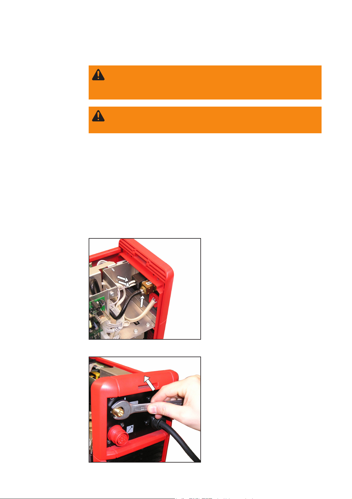
solenoid valve
Operation of the gas controller installation kit is possible with the following PlasmaModule 10 configurations:
- firmware required: OFFICIAL UST V4.26.36
- UST-2C PC board (4,070,960)
1. Switch the PlasmaModule 10 mains switch to the „O“ position
2. Disconnect PlasmaModule 10 from the mains
3. Remove the right side panel
1. Remove „control valve 1“ and „control
valve 2“ connection cables from gas
solenoid valve
2. Open hose clamp using pliers and pull
gas hose off solenoid valve
Removing connection cable and hose
3. Undo hexagon nut using a size 17 flat
spanner and remove solenoid valve
Undoing the hexagon nut
12
Page 37

Fitting and
connecting the
gas solenoid
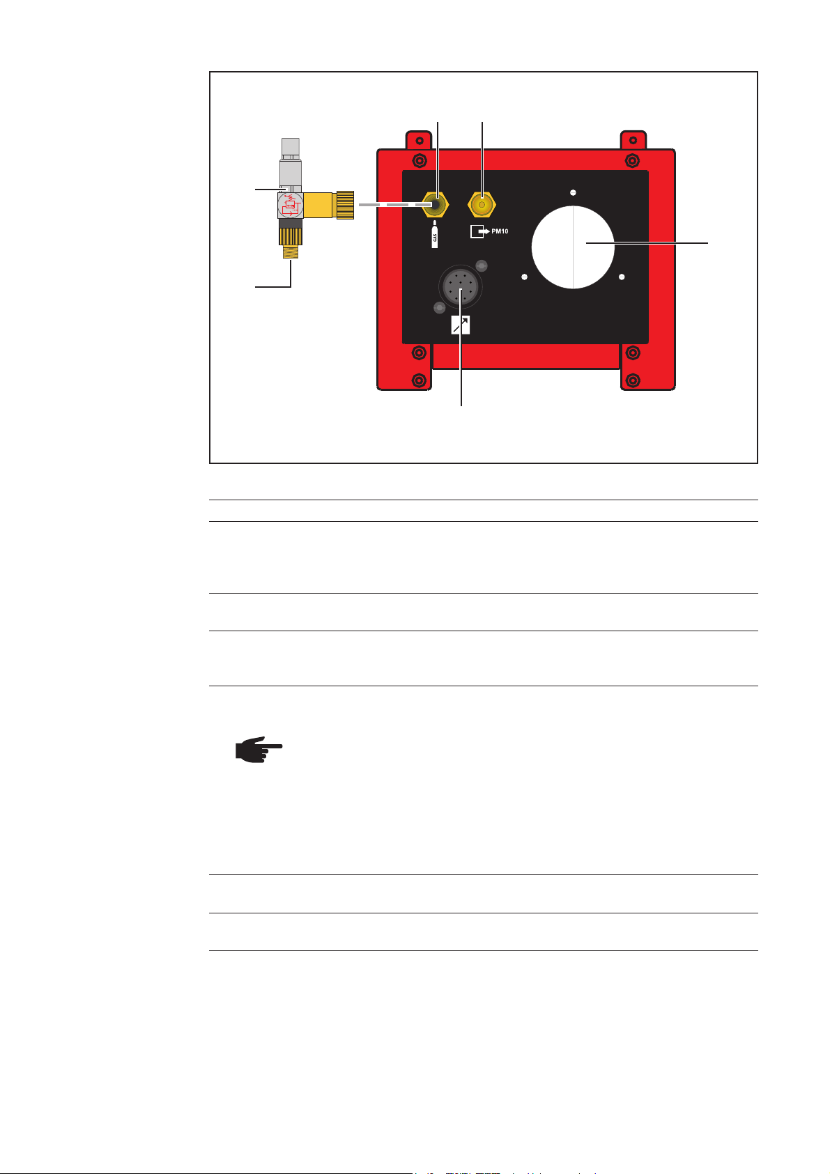
valve
1. Slide on the O-ring and then place the
solenoid valve in the same position
O-ring
Positioning the solenoid valve
Screwing on and tightening the hexagon nut
EN
2. Screw on the hexagon nut and tighten
using size 17 flat spanner
Attaching and fixing the gas hose
3. Slide the gas hose and hose clamp
onto the push-on nipple and tighten
with pliers
Undoing the connection cables Attaching the connection cables
4. Undo the „gas solenoid valve -Y1:A1“ and „gas solenoid valve -Y1:A2“ connection
cables from the cable harness and: connect A1 and A2 to the gas solenoid valve
13
Page 38

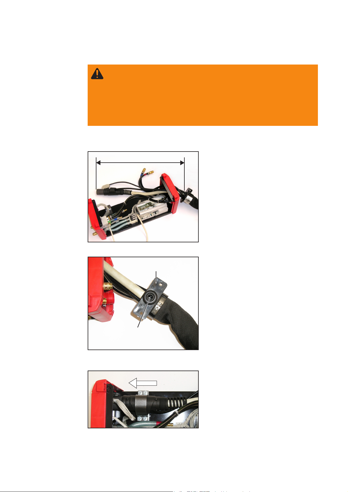
Deactivating
Digital-Gas 10
-X9
Disconnecting the Molex plug
1. Deactivating Digital-Gas 10: remove
the 6-pin Molex plug
-X9 from the UST2C PC board
-X2
Removing the Molex plug from Digi-Gas 10 Plugging the Molex plug onto UST2C
-X9
2. On the Digital-Gas 10 internal gas controller: remove the 6-pin Molex plug X2 and
plug into X9 on the UST2C PC board
Connecting cable
to control device
Routing and fixing the cable harness
3. Route cable harness as shown and fix with cable ties.
Important! The connecting cable to the control device must not be fixed.
14
Page 39

Preparing the swivel pin holder
Mounting the
fitting panels on
the swivel pin
holder
1. Fit the two fitting panels to the swivel
pin holder as shown using three M5 x
10 Extrude-Tite screws for each
EN
Mounting the fitting panels
Mounting the control device on the swivel pin holder
Mounting the
control device on
the holder
Fitting the control device
1. Fit the control device on the holder
and secure using two M5 x 16 Extrude-Tite screws each on the front and
rear sides
15
Page 40

WARNING! An electric shock can be fatal. If the machine is plugged into the
mains electricity supply during installation, there is a high risk of very serious
injury and damage. No work must be carried out unless:
- the device mains switch is in the „O“ position,
- the device is unplugged from the mains
CAUTION! Risk of damage when cables are kinked or damaged.
Damaged cables can cause short circuits and consequently defects in the
PlasmaModule or the control device.
When positioning the PlasmaModule, ensure that the cable is not kinked.
CAUTION! Risk of injury and
damage from devices falling
over.
Ensure that all screw connections are secure.
Connecting the PlasmaModule to the control device
Safety
Connecting the
PlasmaModule to
the control
device
1. Switch the PlasmaModule mains
switch to the „O“ position
2. Unplug the PlasmaModule mains plug
3. If still in place, remove the protective
cover from the underside of the
device
4. Position the PlasmaModule over the
control device using a suitable hoisting device
5. Pull the PlasmaModule Molex connector as far as possible through the
opening on the underside
6. Make the connection between the
PlasmaModule and the control device
Connecting the PlasmaModule to the control device
7. Carefully place PlasmaModule on
control device
8. Using two M5 x 16 Extrude-Tite
screws, fasten the PlasmaModule at
the front and back to the fastening
brackets of the control device.
Fitting the PlasmaModule
16
Page 41

WARNING! An electric shock can be fatal. Before opening the device
- Switch the mains switches on the TIG power source and PlasmaModule to
the „O“ position
- Unplug the device from the mains
- Put up an easy-to-understand warning sign to stop anybody inadvertently
switching it back on again
- Using a suitable measuring instrument, check to make sure that electrically charged components (e.g. capacitors) have discharged
Care, maintenance and disposal
General remarks
Every 6 months
Disposal
Under normal operating conditions, the control device of the installation kit only requires
a minimum of care and maintenance. However, it is vital to observe some important
points to ensure the welding system remains in a usable condition for many years.
- Remove side panels and clean inside of device with dry reduced compressed air
NOTE! Risk of damage to electronic components. Do not bring air nozzle too
close to electronic components.
Dispose of in accordance with the applicable national and local regulations.
EN
Technical data
„Gas controller
installation kit“
control device
Supply voltage 24 V DC (LocalNet)
Protection IP 23
Measurements l x w x h 540 x 180 x 180 mm
Weight 3.12 kg
17
21.3 x 7.1 x 7.1 in.
6.88 lb.
Page 42

Spare parts overview
(1)
(10) (14) (15)
(2)
(5)
(3)
(4)
(6)
(12)
(7) (8)
(9)
(13)(11)
(16)
(22)(21)
(20) (19)
(18)
(17)
18
Page 43

Item Designation Type Item no.
„Gas controller installation kit“ 8,100,150
1 Surface-mounting housing EB 20 14-pin 43,0003,0734
2 Socket strip 42,0405,0154
Insulation 42,0405,0056
Spring 42,0404,0024
3 Digital gas controller Roboflow DFC —4 Red water connection comprising:
Water connection 42,0405,0189
Self-sealing coupling 44,0001,1145
Red nut 42,0405,0186
Hose clamp 16.6 42,0407,0442
5 Black water connection comprising:
Water connection 42,0405,0189
Self-sealing coupling 44,0001,1145
Black nut 42,0405,0187
Hose clamp 16.6 42,0407,0442
6 Pressure reducing valve 44,0001,1299
7 Hose connection nipple 42,0001,1883
Nut 42,0400,0172
8 Self-sealing coupling 44,0001,0473
9 Surface-mounting housing CPC 10-pin 32,0405,0230
10 Gas hose connection comprising:
Gas hose length = 43 cm 40,0001,0012
Push-on nipple 42,0001,1506
Gas connection 44,0450,0281
Hose clamp 12.6 42,0407,0063
11 Connecting cable 10-pin/0.5 m 43,0004,2688
12 ROB-4000 installation kit 4,100,239
13 Flow sensor 0-7 l/min 43,0009,0048
14 Water return hose (red) comprising:
Water hose length = 28 cm 42,0407,0063
Push-on nipple 44,0001,0971
Hose clamp 16.6 42,0407,0442
15 Water return hose (red) comprising:
Water hose length = 17 cm 42,0407,0063
Hose clamp 16.6 42,0407,0442
16 Water flow hose (blue) comprising:
Water hose length = 11 cm 42,0407,0063
Push-on nipple 44,0001,0971
Hose clamp 16.6 42,0407,0442
17 Clamp BP2,0201,2163
18 Connecting cable 43,0004,2678
19 Gas hose length = 41 cm 40,0001,0012
Hose connection nipple 42,0001,0090
Hose clamp 12.6 42,0407,0063
EN
19
Page 44

Item Designation Type Item no.
20 Gas hose length = 42 cm 40,0001,0012
Hose connection nipple 42,0001,0090
Hose clamp 12.6 42,0407,0063
21 Solenoid valve 43,0013,0015
22 Hose clamp 10.0 42,0407,0273
20
Page 45
„Gas controller installation kit“ control device
EN
21
Page 46

PlasmaModule 10
22
Page 47

FRONIUS INTERNATIONAL GMBH
TechSupport Automation
Buxbaumstraße 2, A-4600 Wels, Austria
Tel: +43 (0)7242 241-3520, Fax: +43 (0)7242 241-3900
E-Mail: sales@fronius.com
www.fronius.com
Under http://www.fronius.com/addresses you will find all addresses
www.fronius.com/addresses
of our Sales & service partners and Locations.
ud_fr_st_so_00973 012008
 Loading...