

Page 1

Fronius prints on elemental chlorine free paper (ECF) sourced from certified sustainable forests (FSC).
/ Perfect Charging / Perfect Welding / Solar Energy
Gas Control
0,2 - 10 / 5 - 30 l/min
Bedienungsanleitung
DE
Diverses
Operating instructions
EN
Miscellaneous
Instructions de service
FR
Divers
Návod k obsluze
CS
Různé
Instrukcja obsługi
PL
Pozostałe
42,0410,1461 008-17052021
Page 2

Page 3

Inhaltsverzeichnis
Allgemeines 4
Allgemeines 4
Funktionsprinzip 4
Korrekturfaktor für verwendete Schutzgase 4
Gasspar-Funktion 4
Lieferumfang 4
Zusätzlich erfoderlich 4
Anschlüsse und mechanische Komponenten 5
Sicherheit 5
Anschlüsse und mechanische Komponenten 5
Inbetriebnahme 6
Sicherheit 6
Installation 6
Voraussetzungen für den Betrieb 6
Inbetriebnahme 6
Korrekturfaktoren der gängigsten Schutzgase 7
Maximale Gasströmung 7
Gasspar-Funktion 9
Gasspar-Funktion 9
Kalibrieren der Gasspar-Funktion 9
Fehlerdiagnose und -behebung 11
Sicherheit 11
Allgemeines 11
Angezeigte Service-Codes 11
Technische Daten 13
Gas Control 0,2 - 10 l/min 13
Gas Control 5 - 30 l/min 13
DE
3
Page 4

Allgemeines
Allgemeines Die externen Gasregler ‘Gas Control 0,2 - 10 l/min’ und ‘Gas Control 5 - 30 l/min’ regeln
und dosieren digital die Gasmenge bei MIG/MAG-, WIG- und Plasmaanwendungen.
Je nach Anwendung gewährleistet der externe Gasregler einerseits einen ausreichenden
Gasschutz, andererseits eine stets konstante Gasströmung. Gleichzeitig strömt immer
nur so viel Schutzgas, wie für den jeweiligen Prozess erforderlich ist.
Der externe Gasregler bietet im Job-Betrieb die Möglichkeit, die Gasmengen-Sollwerte
für jeden Job einzeln zu speichern.
Funktionsprinzip Der externe Gasregler verfügt über einen Sensor und ein elektrisches Stellventil. Die
Stromquelle wertet das Mess-Signal des Sensors kontinuierlich aus und sorgt für eine
entsprechende Ansteuerung des Stellventils. Auch bei Verwendung einer mit häufigen
Druckschwankungen behafteten Ringleitung bleibt die Gasströmung auf diese Art konstant.
Korrekturfaktor
für verwendete
Schutzgase
Gasspar-Funktion
Lieferumfang - Externer Gasregler
Zusätzlich erfoderlich
Die Angabe der gewünschten Schutzgas-Menge erfolgt im Setup-Menü der Stromquelle.
In Abhängigkeit des gewählten Zusatz-Werkstoffes stimmt die Stromquelle die Gasmengen-Messung auf das verwendete Schutzgas ab. Werden andere als die vorprogrammierten Schutzgase verwendet, stehen Korrekturfaktoren für die Abgleichung der Regelung zur Verfügung. Somit ist für die anwählbaren Materialarten ein exaktes Einhalten
der gewünschten Schutzgasmenge sichergestellt.
Die Gasspar-Funktion bewirkt eine optimierte Erstöffnung des Stellventils und sorgt
durch eine kaum erhöhte Gasströmung für eine Gas-Einsparung zu Schweißbeginn.
Werksseitig ist die Gasspar-Funktion auf einen Schutzgas-Eingangsdruck von 3 bar (43
psi.) eingestellt. Ein Tastendruck genügt, um die Gassparfunktion auch auf andere Gasdruck-Werte zu optimieren.
- Gasschlauch
- LocalNet-Kabel
4
Page 5

Anschlüsse und mechanische Komponenten
(1)
(2)
NI SAG
(3)
(4)
TUO SAG
(5)
DE
Sicherheit
Anschlüsse und
mechanische
Komponenten
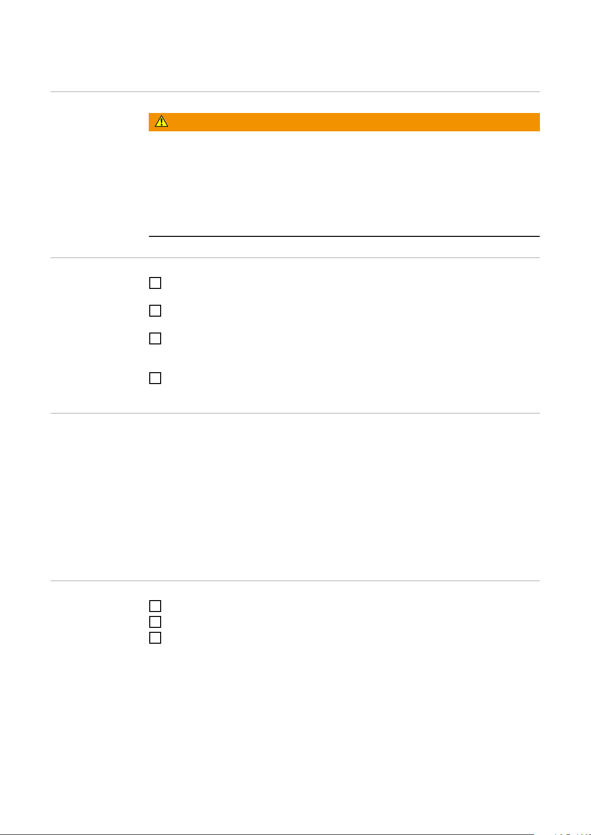
WARNUNG!
Gefahr durch Fehlbedienung und fehlerhaft durchgeführte Arbeiten.
Schwerwiegende Personen- und Sachschäden können die Folgen sein.
Alle in diesem Dokument beschriebenen Arbeiten und Funktionen dürfen nur von
▶
geschultem Fachpersonal ausgeführt werden, wenn folgende Dokumente
vollständig gelesen und verstanden wurden:
dieses Dokument
▶
sämtliche Dokumente der Systemkomponenten, insbesondere Sicherheitsvorschrif-
▶
ten
Vorderseite / Seite / Rückseite
(1) Anschluss LocalNet
(2) Anschluss ‘GAS IN’
(3) Blindabdeckung
(4) Anschluss ‘GAS OUT’
(5) Montagehalterung
5
Page 6

Inbetriebnahme
Sicherheit
Installation
WARNUNG!
Gesundheitsgefährdung und Erstickungsgefahr durch farb- und geruchloses
Schutzgas.
Schwerwiegende Personenschäden können die Folge sein.
Werden die nachfolgend angeführten Hinweise nicht beachtet, besteht nach
▶
Schweißende die Gefahr eines nicht vollständig schließenden Stellventils. Es könnte
unbemerkt farb- und geruchloses Schutzgas entweichen.
Den maximalen Eingangsdruck der Schutzgas-Versorgung nicht überschreiten. Der
▶
maximale Eingangsdruck beträgt 7 bar (101.49 psi).
Externen Gasregler mittels Montagehalterung an geeigneter Position montieren (z.B.
1
am Fahrwagen).
Anschluss LocalNet des externen Gasreglers mittels LocalNet-Kabel mit einem
2
freien Anschluss LocalNet an Stromquelle oder Drahtvorschub verbinden.
Anschluss ‘Schutzgas-Versorgung’ an Stromquelle oder Drahtvorschub mittels mit-
3
geliefertem Gasschlauch mit dem Anschluss ‘GAS OUT’ des externen Gasreglers
verbinden.
Gasschlauch mit der Schutzgas-Versorgung (z.B. Gasflasche) verbinden und am
4
externen Gasregler ‘GAS IN’ anschließen
Voraussetzungen
für den Betrieb
Inbetriebnahme
Damit der externe Gasregler erforderlichenfalls den maximal möglichen Wert für die
Gasströmung erreichen kann, folgende Hinweise beachten:
- Falls vorhanden, den Druckminderer der Schutzgas-Versorgung nach dem
Anschließen des Gasschlauches vollständig öffnen.
WICHTIG! Der Druckminderer mit Messrohr (Artikelnummer: 43,0011,0008) lässt
keinen ausreichenden Eingangsdruck zu und ist somit nicht geeignet.
- Bei gleichzeitiger Verwendung von zwei oder mehreren externen Gasreglern (z.B.
für TimeTwin Digital), nur jeweils einen Drahtvorschub an eine Gasflasche oder an
eine Abnahmestelle der Ringleitung anschließen.
- Maximaler Eingangsdruck der Schutzgas-Versorgung: 7 bar (101.49 psi.)
Schweißanlage am Netz anschließen
1
Netzschalter der Stromquelle in Stellung - I - schalten
2
Im Setup-Menü der Stromquelle den Parameter ‘GAS’ (Gasflow) auf die gewünschte
3
Gasstömung einstellen:
- Je nach vorhandenem Gasregler gibt es für den Parameter ‘GAS’ unterschiedliche Einstellungen:
a) OFF / 0,2 - 10 l/min (Einstellschritte 0,1 l/min)
b) OFF / 5,0 - 30 l/min (Einstellschritte 1 l/min)
- Die Einstellung ‘OFF’ ist nur bei Verwendung von Schweißdrähten erforderlich,
welche ohne Schutzgas verarbeitet werden.
- Ist der Setup-Parameter ‘SEt’ auf ‘US’ eingestellt, erfolgt die Angabe der Gasströmung in „cubic feet per hour“ (cfh).
6
Page 7

Je nach vorhandenem Schutzgas den Parameter ‘COr’ (Korrekturfaktor) im Setup-
7\S
7\S
/LQGH
/LQGH
0HVVHU
0HVVHU
',1(1
',1(1
$LU/LTXLGH
$LU/LTXLGH
&25
&25
TIME I 8 0,5 65 26,5 - - T.I.M.E o - M24(1) 2,41
M21 Ar+18%CO2 18 - 82 - - - Corgon 18 Krysal 18 Artal M21 1,56
C1 100% CO2 100 - - - - - Kohlendioxid Kohlensäure Kohlendioxid C1 1
M12 Ar+2,5%CO2 2,5 - 97,5 - - - Cronigon 2 Argomag K o M12 1,68
I1 100% Ar - - 100 - - - Argon Argon 4.8 Alphagaz A I1 1,76
M13 Ar+3% O2 - 3 97 - - - Cronigon S3 Argomag S3 - M13 1,74
M23 Ar+CO2+O2 5 4 91 - - - Corgon 1 o - M23 1,66
M21 Ar+15%CO2 15 - 85 - - - Corgon 15 o - M21 1,58
M22 Ar+4%O2 - 4 96 - - - - Argomix 4 Cargal M22 1,72
M24 Ar+CO2+O2 13 4 83 - - - Corgon 2 o - M24 1,55
M21 Ar+20%CO2 20 - 80 - - - Corgon 20 o - M24 1,53
M13 Ar+2% O2 - 2 98 - - - o o - M13 1,74
I3 Ar+50%He - - 50 50 - - Varigon He 50 Argon He 50 Arcal 35 I3 3,78
M12 Ar+2%CO2 2 - 98 - - - o o Arcal 12 M12 1,69
M22 Ar+8%O2 - 8 92 - - - Corgon S8 Argomix D - M22 1,71
M13 Ar+He+O2 - 0,05 69,95 30 - - o o - M13(1) 2,73
M21 Ar+8%CO2 8 - 92 - - - Corgon 8 Krysal 8 Arcal 21 M21 1,66
Ar78He20CO2 2 2 - 78 20 - - Cronigon He 20 o - M12 (1) 2,27
Ar68He30CO2 2 2 - 68 30 - - o o Arcal 121 M12(1) 2,59
I3 Ar+15%He - - 85 15 - - o o - I3 1,94
I3 Ar+25%He - - 75 25 - - o o - I3 2,7
I3 Ar+30%He - - 70 - 30 - o o - R2 2,72
Ar+2%O2 - 2 98 - - - o o Arcal 22 M13 1,74
Ar+1000ppmO2 - - 0,1 99,9 - - o o - M13 1,76
I3 Ar+30He+N2 - - 69,98 30 - 0,02 o o - S I3+0,02N2 2,7
I3 Ar+75%HE - - 25 75 - - o o - I3 5,98
HT5 - 5 95 - - - Corgon S5 o - M22 1,72
HT10 - - 85 10 - 5 o o - S I3+5N2 1,97
S5 - 5 95 - - - Corgon S5 o - M22 1,71
Corgon 25 25 - 75 - - - Corgon 25 o - M21 1,5
Mixture 0,05 - 79,95 20 - - o o - M12(1) 2,24
Mixture - - 73 25 2 - o o - R1(1) 2,48
Mixture 4 1 95 - - - o o - M14 1,67
Cronigon N3 - - 97 - - 3 o o - S I1+3N2 1,7
Cronigon N5 - - 95 - - - o o - S I1+5N2 1,68
&2
&222$U$U+H+H++11
Cronigon NH - - 97 - 1 2 Croniwig NH o - S R1+2N2 1,7
Corgon He 25 C 25 - 50 25 - - Corgon He 25 C 0 - M21(1) 2,02
Corgon 5 5 - 95 - - - 0 0 - M12 1,68
Varigon He - - 10 90 - - Varigon He 90 Argon He 90 - I3 8,35
Varigon H2 - - 98 - 2 - Varigon H2 Argon W2 - R1 1,79
Varigon H3 - - 97 - 3 - Varigon H3 o - R1 1,77
Varigon H5 - - 95 - 5 - Varigon H5 Argon W5 Arcal 15 R1 1,75
Mixture - 1 99 - - - Cronigon S1 Argomag S1 - M13 1,76
4
Menü der Stromquelle anpassen
- Einstellbereich für den Parameter ‘COr’: AUT / 1,0 - 9,9
- Ist der Parameter ‘COr’ auf ‘AUT’ eingestellt, wird der werksseitig vorprogrammierte Korrekturfaktor für den ausgewählten Zusatz-Werkstoff übernommen.
DE
Korrekturfaktoren
der gängigsten
Nachfolgend dargestellte Tabelle gibt den Korrekturfaktor ‘COR’ für die gängigsten Gasgemische an.
Schutzgase
Maximale Gasströmung
Die maximale Gasströmung errechnet sich wie folgt:
Maximale Gasströmung (l/min) = 20 x Korrekturfaktor
7
Page 8

WICHTIG! Ergibt sich eine Gasströmung größer als die maximal einstellbare Gasmenge,
wird diese auf die maximal einstellbare Gasmenge begrenzt.
Ab einem Korrekturfaktor < 1,5 verringert sich die maximale Gasmenge.
8
Page 9

Gasspar-Funktion
(1)
‘GAS’
t (s)
(2)
(3)
t (s)
‘GAS’
(1)
DE
Gasspar-Funktion
Die Gasspar-Funktion bewirkt eine optimierte Erstöffnung des Stellventils und sorgt
durch eine kaum erhöhte Gasströmung für eine Gas-Einsparung zu Schweißbeginn.
Werksseitig ist die Gasspar-Funktion auf einen Schutzgas-Eingangsdruck von 3 bar (43
psi.) eingestellt.
Verlauf der Gasströmung ohne Gasregler
Gasspar-Funktion: Verlauf der Gasströmung mit Gasregler
(1) Gasströmung (l/min)
(2) großer Überschuss
(3) fast kein Überschuss
Kalibrieren der
Gasspar-Funktion
Ein Optimieren der Gasspar-Funktion ist auch auf andere Gasdruck-Werte möglich.
Weicht der Eingangsdruck der Schutzgas-Versorgung von 3 bar (43 psi) ab, die
Gasspar-Funktion wie folgt kalibrieren:
Schutzgas-Versorgung herstellen (z.B. Gasflaschen-Ventil und Druckminderer
1
öffnen)
Stromquelle einschalten
2
Der Kalibriervorgang erfolgt automatisch und ist nach einer halben Sekunde abgeschlossen.
Besteht beim Einschalten der Stromquelle noch keine Schutzgas-Versorgung (z.B.
Gasflaschen-Ventil ist nicht geöffnet), zeigt das Display den Service-Code
‘no | GAS’.
Nach dem Herstellen der Schutzgas-Versorgung den Service-Code ‘no | GAS’ durch
Drücken der Taste ‘Store’ quittieren.
Kalibriervorgang bei eingeschalteter Stromquelle:
9
Page 10

An der Stromquelle die Taste ‘Gasprüfen’ zweimal kurz drücken
1
- Der Kalibriervorgang erfolgt automatisch und ist nach einer halben Sekunde
abgeschlossen.
- Beim einmaligen Drücken der Taste ‘Gasprüfen’ strömt für 30 Sekunden Schutzgas aus. Beim wiederholten Drücken der Taste ‘Gasprüfen’ wird das Schutzgas
vorzeitig gestoppt, gleichzeitig startet der Kalibriervorgang.
Kalibriervorgang beim Einsatz eines Roboterinterfaces ROB 4000 / 5000 oder
eines Feldbus-Kopplers:
Das Signal ‘Gas Test’ kurzzeitig auf ‘1’ setzen
1
Das Signal ‘Gas Test’ anschließend wieder auf ‘0’ zurücksetzen
2
Bei der fallenden Flanke des Signales ‘Gas Test’ erfolgt der Start des Kalibriervorganges.
Für automatisierte Anwendungen empfehlen wir, die Zeit während Bauteilwechsel oder
Brennerreinigung für den Kalibriervorgang zu nützen. Obwohl der Kalibriervorgang nur
eine halbe Sekunde dauert, aus Gründen der Prozess-Sicherheit einen Zeitraum von 3
Sekunden einkalkulieren.
WICHTIG! Wird der Schweißprozess während eines Kalibriervorganges gestartet, erfolgt
ein sofortiger Abbruch des Kalibriervorganges. Die Optimierung der Gasspar-Funktion
verbleibt entsprechend dem letzten Kalibriervorgang.
WICHTIG! Erscheint während des Kalibriervorganges ein Service-Code am Bedienpanel
(z.B. Err | 70.3), verbleibt die Optimierung der Gasspar-Funktion entsprechend dem letzten Kalibriervorgang.
- Gegebenenfalls den Kalibriervorgang erneut starten
10
Page 11

Fehlerdiagnose und -behebung
DE
Sicherheit
WARNUNG!
Fehlbedienung und fehlerhaft durchgeführte Arbeiten können schwerwiegende
Personen- und Sachschäden verursachen.
Alle in diesem Dokument beschriebenen Arbeiten und Funktionen dürfen nur von
▶
geschultem Fachpersonal ausgeführt werden, wenn folgende Dokumente
vollständig gelesen und verstanden wurden:
dieses Dokument,
sämtliche Dokumente der Systemkomponenten, insbesondere Sicherheitsvorschriften.
WARNUNG!
Ein elektrischer Schlag kann tödlich sein.
Vor Beginn der Arbeiten:
Netzschalter der Stromquelle in Stellung - O - schalten
▶
Stromquelle vom Netz trennen
▶
sicherstellen, dass die Stromquelle bis zum Abschluss aller Arbeiten vom Netz
▶
getrennt bleibt
Nach dem Öffnen des Gerätes mit Hilfe eines geeigneten Messgerätes sicherstel-
▶
len, dass elektrisch geladene Bauteile (z.B. Kondensatoren) entladen sind.
VORSICHT!
Verletzungsgefahr durch heiße Systemkomponenten.
Vor Beginn der Arbeiten alle heißen Systemkomponenten auf Zimmertemperatur
▶
(+25 °C, +77 °F) abkühlen lassen.
Allgemeines Im folgenden sind Service-Codes in Zusammenhang mit dem externen Gasregler
angeführt. Alle anderen Service-Codes sind in der Bedienungsanleitung der Stromquelle
beschrieben.
WICHTIG! Ist eine hier angeführte Behebungsmaßnahme nicht erfolgreich, darf der Fehler nur durch den Servicedienst behoben werden. Notieren Sie die angezeigte Fehlermeldung sowie Seriennummer und Konfiguration der Stromquelle und verständigen Sie
den Servicedienst mit einer detaillierten Fehlerbeschreibung.
Angezeigte Service-Codes
Err | 70.1
Ursache:
Behebung:
Gasmengen-Sensor wurde nicht gefunden
Anschlüsse der Signalleitung für den Gasmengen-Sensor überprüfen
11
Page 12

no | GAS
Ursache:
Behebung:
Err | 70.3
Ursache:
Behebung:
Err | 70.4
Ursache:
Behebung:
Err | 70.5
Ursache:
Behebung:
Schutzgas-Versorgung nicht vorhanden oder nicht ausreichend
Schutzgas-Versorgung nicht vorhanden oder nicht ausreichend Behebung:
Schutzgas-Versorgung herstellen (z.B. Gasflaschen-Ventil und Druckminderer vollständig öffnen), no | GAS durch Drücken der Taste „Store“ quittieren,
oder bei Verwendung eines Roboterinterfaces ROB 5000 bzw. FeldbusKopplers mittels digitalem Eingangssignal „Quellenstörung quittieren“
(„Source error reset“) resetieren.
Kalibrier-Fehler: Eingangsdruck am Druckregelungs-Ventil ist zu hoch oder
Druckregelungs-Ventil ist defekt.
Eingangsdruck am Druckregelungs-Ventil auf höchstens 7 bar (101.49 psi.)
verringern oder Druckregelungs-Ventil erneuern , Err | 70.3 durch Drücken
der Taste Store quittieren
Stellventil defekt
Stellventil austauschen
Stellventil wurde nicht gefunden
Anschlüsse der Signalleitung für das Stellventil überprüfen
12
Page 13

Technische Daten
DE
Gas Control 0,2 10 l/min
Regelbereich 0,2 - 10 l/min
(0.43 - 21.43 cfh)
Versorgungsspannung 24 V
Maximaler Eingangsdruck 7 bar
(101.49 psi)
Toleranz +/- 10 % vom Endwert (max.)
Linearität +/- 4 % vom Messwert (max.)
Hysterese +/- 0,5 % vom Messwert (max.)
Temperaturabhängigkeit bei CO
Temperaturabhängigkeit bei Argon +/- 7 % vom Messwert (max.)
Schutzart IP 23
Maße l / b / h 380 / 65 / 150 mm
Gewicht 2,4 kg
2
+/- 10 % vom Messwert (max.)
bei -20 °C bis 70 °C
(bei -4 °F bis 158 °C)
bei -20 °C bis 70 °C
(bei -4 °F bis 158 °C)
(14.96 / 2.56 / 5.91 in.)
(5.29 lbs.)
Gas Control 5 30 l/min
Prüfzeichen S, CE
Regelbereich 5 - 30 l/min
(10.71 - 64.29 cfh)
Versorgungsspannung 24 V
Maximaler Eingangsdruck 7 bar
(101.49 psi)
Toleranz +/- 10 % vom Endwert (max.)
Linearität +/- 4 % vom Messwert (max.)
Hysterese +/- 0,5 % vom Messwert (max.)
Temperaturabhängigkeit bei CO
Temperaturabhängigkeit bei Argon +/- 7 % vom Messwert (max.)
Schutzart IP 23
2
+/- 10 % vom Messwert (max.)
bei -20 °C bis 70 °C
(bei -4 °F bis 158 °C)
bei -20 °C bis 70 °C
(bei -4 °F bis 158 °C)
Maße l / b / h 380 / 65 / 150 mm
(14.96 / 2.56 / 5.91 in.)
Gewicht 2,4 kg
(5.29 lbs.)
Prüfzeichen S, CE
13
Page 14

14
Page 15

Contents
General 16
General 16
Functional principle 16
Correction factor for shielding gases 16
Gas saving function 16
Scope of supply 16
Also required 16
Connections and mechanical components 17
Safety 17
Connections and mechanical components 17
Start-up 18
Safety 18
Installation 18
Prerequisites for operation 18
Commissioning 18
Correction factors for common shielding gases 19
Maximum gas flow 19
Gas saving function 20
Gas saving function 20
Calibrating the gas saving function 20
Troubleshooting 22
Safety 22
General 22
Displayed service codes 22
Technical data 24
Gas Control 0,2 - 10 l/min 24
Gas Control 5 - 30 l/min 24
EN
15
Page 16

General
General The external gas controllers ‘Gas Control 0.2 - 10 l/min’ and ‘Gas Control 5 - 30 l/min’
digitally control and modulate the gas flow for MIG/MAG, TIG and plasma applications.
Depending on the application, the external gas controller guarantees both sufficient protection while providing a constant gas flow. It provides only the amount of shielding gas
required for the process in hand.
In Job mode, the external gas controller enables the set gas flow values to be saved for
each individual job
Functional
principle
Correction factor
for shielding
gases
Gas saving function
Scope of supply - External gas controller
The external gas controller has a sensor and an electrical control valve. The power
source continuously analyses the measuring signal from the sensor and actuates the
control valve accordingly. The gas flow remains constant, even when used with a ring
main marred by frequent pressure fluctuations.
The desired shielding gas quantity can be entered in the power source setup menu.
Depending on the selected filler metal, the power source matches the gas flow measurement to the shielding gas used. Correction factors are available for adjusting the controller if shielding gases other than the pre-programmed ones are used. This ensures precise maintenance of the desired shielding gas flow for the selected material type.
The gas saving function ensures an optimum initial opening of the control valve and
saves gas when welding begins by hardly increasing the gas flow. The gas saving function is factory set to a shielding gas supply pressure of 3 bar (43 psi), but can be adjusted at the touch of a button.
- Gas hose
Also required - LocalNet cable
16
Page 17

Connections and mechanical components
(1)
(2)
NI SAG
(3)
(4)
TUO SAG
(5)
Safety
Connections and
mechanical components
WARNING!
Danger due to incorrect operation and incorrectly performed work.
This can result in serious injury and damage to property.
All functions described in this document may only be carried out by trained and qua-
▶
lified personnel after they have fully read and understood the following documents:
this document
▶
all documents relating to the system components, especially the safety rules
▶
EN
Front / Page / Rear
(1) LocalNet port
(2) GAS IN’ connection
(3) Blanking cover
(4) ‘GAS OUT’ connection
(5) Mounting bracket
17
Page 18

Start-up
Safety
Installation
WARNING!
Shielding gas is colourless and odourless, is hazardous to health and can cause
asphyxiation.
This can result in serious injury to property.
If the following instructions are not observed, there is a risk that the control valve will
▶
not close completely when welding has finished. Colourless and odourless shielding
gas may escape undetected.
Never exceed the maximum supply pressure of the shielding gas. The maximum
▶
supply pressure is 7 bar (101.49 psi).
Mount the external gas controller in a suitable position using the mounting bracket
1
(e.g. on the trolley)
Connect the LocalNet connection on the external gas controller to a free LocalNet
2
connection on the power source or wirefeeder using the LocalNet cable.
Connect the ‘shielding gas supply’ connection on the power supply or wirefeeder to
3
the ‘GAS OUT’ connection on the external gas controller using the gas hose supplied.
Connect the gas hose with the shielding gas supply (e.g. gas cylinder) and to the
4
external gas controller ‘GAS IN’.
Prerequisites for
operation
Commissioning
Note the following to ensure that the external gas controller is able, if required, to reach
the maximum possible gas flow value:
- If the shielding gas supply has a pressure regulator, open it fully after connecting the
gas hose.
IMPORTANT! The pressure regulator with metering tube (item number:
43,0011,0008) is not suitable, as it does not allow a sufficient supply pressure.
- If two or more external gas controllers are used together (e.g. for TimeTwin Digital),
only connect one wirefeeder to each gas cylinder or ring main tap.
- The maximum supply pressure is 7 bar (101.49 psi).
Connect welding system to the mains
1
Turn the power source mains switch to the „I“ position
2
In the power source set-up menu, set the ‘GAS’ (Gasflow) parameter to the desired
3
gas flow:
- There are various settings for the ‘GAS’ parameter depending on the type of gas
controller:
a) OFF / 0.2 - 10 l/min (increment 0.1 l/min)
b) OFF / 5.0 - 30 l/min (increment 1 l/min)
- The ‘OFF’ setting is only required when filler wire that is processed without shielding gas is being used.
- When the set-up parameter ‘SEt’ is set to ‘US’, the gas flow is shown in „cubic
feet per hour“ (cfh).
18
Page 19

Correction fac-
7\S
7\S
/LQGH
/LQGH
0HVVHU
0HVVHU
',1(1
',1(1
$LU/LTXLGH
$LU/LTXLGH
&25
&25
TIME I 8 0,5 65 26,5 - - T.I.M.E o - M24(1) 2,41
M21 Ar+18%CO2 18 - 82 - - - Corgon 18 Krysal 18 Artal M21 1,56
C1 100% CO2 100 - - - - - Kohlendioxid Kohlensäure Kohlendioxid C1 1
M12 Ar+2,5%CO2 2,5 - 97,5 - - - Cronigon 2 Argomag K o M12 1,68
I1 100% Ar - - 100 - - - Argon Argon 4.8 Alphagaz A I1 1,76
M13 Ar+3% O2 - 3 97 - - - Cronigon S3 Argomag S3 - M13 1,74
M23 Ar+CO2+O2 5 4 91 - - - Corgon 1 o - M23 1,66
M21 Ar+15%CO2 15 - 85 - - - Corgon 15 o - M21 1,58
M22 Ar+4%O2 - 4 96 - - - - Argomix 4 Cargal M22 1,72
M24 Ar+CO2+O2 13 4 83 - - - Corgon 2 o - M24 1,55
M21 Ar+20%CO2 20 - 80 - - - Corgon 20 o - M24 1,53
M13 Ar+2% O2 - 2 98 - - - o o - M13 1,74
I3 Ar+50%He - - 50 50 - - Varigon He 50 Argon He 50 Arcal 35 I3 3,78
M12 Ar+2%CO2 2 - 98 - - - o o Arcal 12 M12 1,69
M22 Ar+8%O2 - 8 92 - - - Corgon S8 Argomix D - M22 1,71
M13 Ar+He+O2 - 0,05 69,95 30 - - o o - M13(1) 2,73
M21 Ar+8%CO2 8 - 92 - - - Corgon 8 Krysal 8 Arcal 21 M21 1,66
Ar78He20CO2 2 2 - 78 20 - - Cronigon He 20 o - M12 (1) 2,27
Ar68He30CO2 2 2 - 68 30 - - o o Arcal 121 M12(1) 2,59
I3 Ar+15%He - - 85 15 - - o o - I3 1,94
I3 Ar+25%He - - 75 25 - - o o - I3 2,7
I3 Ar+30%He - - 70 - 30 - o o - R2 2,72
Ar+2%O2 - 2 98 - - - o o Arcal 22 M13 1,74
Ar+1000ppmO2 - - 0,1 99,9 - - o o - M13 1,76
I3 Ar+30He+N2 - - 69,98 30 - 0,02 o o - S I3+0,02N2 2,7
I3 Ar+75%HE - - 25 75 - - o o - I3 5,98
HT5 - 5 95 - - - Corgon S5 o - M22 1,72
HT10 - - 85 10 - 5 o o - S I3+5N2 1,97
S5 - 5 95 - - - Corgon S5 o - M22 1,71
Corgon 25 25 - 75 - - - Corgon 25 o - M21 1,5
Mixture 0,05 - 79,95 20 - - o o - M12(1) 2,24
Mixture - - 73 25 2 - o o - R1(1) 2,48
Mixture 4 1 95 - - - o o - M14 1,67
Cronigon N3 - - 97 - - 3 o o - S I1+3N2 1,7
Cronigon N5 - - 95 - - - o o - S I1+5N2 1,68
&2
&222$U$U+H+H++11
Cronigon NH - - 97 - 1 2 Croniwig NH o - S R1+2N2 1,7
Corgon He 25 C 25 - 50 25 - - Corgon He 25 C 0 - M21(1) 2,02
Corgon 5 5 - 95 - - - 0 0 - M12 1,68
Varigon He - - 10 90 - - Varigon He 90 Argon He 90 - I3 8,35
Varigon H2 - - 98 - 2 - Varigon H2 Argon W2 - R1 1,79
Varigon H3 - - 97 - 3 - Varigon H3 o - R1 1,77
Varigon H5 - - 95 - 5 - Varigon H5 Argon W5 Arcal 15 R1 1,75
Mixture - 1 99 - - - Cronigon S1 Argomag S1 - M13 1,76
tors for common
shielding gases
Adjust the ‘COr’ (correction factor) parameter in the set-up menu to the power
4
source according to the shielding gas being used
- Range for ‘COr’ parameter: AUT / 1.0 - 9.9
- If the ‘COr’ parameter is set to ‘AUT’, the factory set pre-programmed correction
factor for the selected filler metal is used.
The following table shows the ‘COR’ correction factors for common gas mixtures.
EN
Maximum gas
flow
The maximum gas flow is calculated as follows:
Maximum gas flow (l/min) = 20 x correction factor
IMPORTANT! If this results in a gas flow value greater than the maximum settable gas
quantity, use the maximum settable quantity.
With a correction factor < 1.5 the maximum gas quantity reduces.
19
Page 20

Gas saving function
(1)
‘GAS’
t (s)
(2)
(3)
t (s)
‘GAS’
(1)
Gas saving function
The gas saving function ensures an optimum initial opening of the control valve and
saves gas when welding begins by hardly increasing the gas flow. The gas saving function is factory set to a shielding gas supply pressure of 3 bar (43 psi).
Plot of gas flow without gas controller
Gas saving function: plot of gas flow with gas controller
(1) Gas flow (l/min)
(2) large surplus
(3) hardly any surplus
Calibrating the
gas saving function
The gas saving function can be optimised by adjusting it to other gas pressure values.
If the supply pressure deviates from the shielding gas supply of 3 bar (43 psi), calibrate the gas supply function as follows:
Establish a shielding gas supply (e.g. open the gas cylinder valve and pressure
1
reducer)
Switch on the power source
2
Calibration is carried out automatically and takes half a second.
If there is still no shielding gas supply after the power source is switched on (e.g. gas
cylinder is not open), the display will show the service code
‘no | GAS’.
After establishing the shielding gas supply, press the ‘Store’ button to acknowledge
the ‘no | GAS’ service code
Calibration process when power source is switched on
20
Page 21

Press the ‘Gas Test’ button on the power source twice in quick succession
1
- Calibration is carried out automatically and takes half a second.
- Pressing the ‘Gas Test’ button once causes shielding gas to flow out for 30 s.
Pressing the ‘Gas Test’ button again interrupts the flow of shielding gas and
starts the calibration process.
Calibration process when using a ROB 4000 / 5000 robot interface or a field bus
coupler:
Temporarily set the ‘Gas test’ signal to ‘1’
1
Reset the ‘Gas test’ signal to ‘0’
2
The calibration process begins at the falling edge of the ‘Gas Test’ signal.
For automated applications, we recommend that you carry out the calibration process
while the torch is being cleaned or components are being exchanged. Although the calibration process only lasts half a second, allow three seconds for process safety reasons.
EN
IMPORTANT! If welding starts while the calibration is in progress, the calibration stops
immediately. The optimisation of the gas saving function remains as it was for the last
calibration process.
IMPORTANT! If a service code appears on the control panel (e.g. Err | 70.3), optimisation of the gas saving function remains as it was for the last calibration process.
- If necessary, restart the calibration process
21
Page 22

Troubleshooting
Safety
WARNING!
Incorrect operation or shoddy workmanship can cause serious injury or damage.
All functions described in this document may only be carried out by trained and qua-
▶
lified personnel after they have fully read and understood the following documents:
this document,
all documents relating to the system components, especially the safety rules!
WARNING!
An electric shock can be fatal.
Before starting work:
turn the power source mains switch to the "O" position
▶
disconnect the power source from the mains
▶
ensure that the power source remains disconnected from the mains until all work
▶
has been completed
After opening the device, use a suitable measuring instrument to check that electri-
▶
cally charged components (e.g. capacitors) have been discharged.
CAUTION!
Risk of injury from hot system components.
Before starting work, allow all hot system components to cool down to room tempe-
▶
rature (+25°C, +77°F).
General The following is a list of service codes related to the external gas controller. For all other
service codes, refer to the „Troubleshooting“ section in the power source operating instructions.
IMPORTANT! If the troubleshooting measure listed here is not successful, then the error
must be rectified by our After-Sales Service team. Make a note of the error message
shown in the display, and of the serial number and configuration of the power source,
and contact our After-Sales Service team with a detailed description of the error.
Displayed service
codes
Err | 70.1
Cause:
Remedy:
no | GAS
Cause:
Remedy:
Gas flow sensor not found
Check signal cable connections for the gas flow sensor
Shielding gas supply not available or no sufficient
Connect shielding gas supply (e.g. open gas cylinder valve and pressure
reducer wide), acknowledge “no | GAS“ by pressing the “Store“ button or
reset by means of the digital input signal “Source error reset“ if a ROB 5000
robot interface or a field-bus coupler is used.
22
Page 23

Err | 70.3
Cause:
Remedy:
Err | 70.4
Cause:
Remedy:
Err | 70.5
Cause:
Remedy:
Calibration error: Supply pressure at pressure regulating valve is too high or
pressure regulating valve is faulty.
Reduce supply pressure at pressure regulating valve to no more than 7 bar
(101.49 psi) or replace pressure regulating valve Reset 'Err | 70.3' by pressing the 'Store' button
EN
Control valve faulty
Replace control valve
Control valve not found
Check connections of the control valve signal cable
23
Page 24

Technical data
Gas Control 0,2 10 l/min
Control range 0,2 - 10 l/min
(0.43 - 21.43 cfh)
Supply voltage 24 V
Maximum supply pressure 7 bar
(101.49 psi)
Range of tolerance +/- 10 % of the final value (max.)
Linearity +/- 4 % of the measurement (max.)
Hysteresis +/- 0,5 % of the measurement (max.)
Temperature dependence with CO
Temperature dependence with Argon +/- 7 % of the measurement (max.)
Protection IP 23
Dimensions l/w/h 380 / 65 / 150 mm
Weight 2,4 kg
2
+/- 10 % of the measurement (max.)
at -20 °C to 70 °C
(at -4 °F to 158 °C)
at -20 °C to 70 °C
(at -4 °F to 158 °C)
(14.96 / 2.56 / 5.91 in.)
(5.29 lbs.)
Gas Control 5 30 l/min
Marks of conformity S, CE
Control range 5 - 30 l/min
(10.71 - 64.29 cfh)
Supply voltage 24 V
Maximum supply pressure 7 bar
(101.49 psi)
Range of tolerance +/- 10 % of the final value (max.)
Linearity +/- 4 % of the measurement (max.)
Hysteresis +/- 0,5 % of the measurement (max.)
Temperature dependence with CO
Temperature dependence with Argon +/- 7 % of the measurement (max.)
Protection IP 23
2
+/- 10 % of the measurement (max.)
at -20 °C to 70 °C
(at -4 °F to 158 °C)
at -20 °C to 70 °C
(bat -4 °F to 158 °C)
24
Dimensions l/w/h 380 / 65 / 150 mm
(14.96 / 2.56 / 5.91 in.)
Weight 2,4 kg
(5.29 lbs.)
Marks of conformity S, CE
Page 25

Sommaire
Généralités 26
Généralités 26
Principe de fonctionnement 26
Facteur de correction pour les gaz protecteurs utilisés 26
Fonction Économie de gaz 26
Livraison 26
Autres accessoires nécessaires 26
Raccords et composants mécaniques 27
Sécurité 27
Raccords et composants mécaniques 27
Mise en service 28
Sécurité 28
Installation 28
Configurations de fonctionnement 28
Mise en service 28
Facteurs de correction des gaz protecteurs les plus courants 29
Débit de gaz maximal 29
Fonction Économie de gaz 31
Fonction Économie de gaz 31
Calibrage de la fonction Économie de gaz 31
Diagnostic et élimination des pannes 33
Sécurité 33
Généralités 33
Codes de service affichés 33
Caractéristiques techniques 35
Gas Control 0,2 - 10 l/min 35
Gas Control 5 - 30 l/min 35
FR
25
Page 26

Généralités
Généralités Le régulateur de débit de gaz externe „Gas Control 0,2 - 10 l/min“ et „Gas Control 5 - 30
l/min“ est un système numérique qui régule et dose la quantité de gaz dans les applications MIG/MAG, TIG et Plasma.
En fonction de l’utilisation, le régulateur de débit de gaz externe garantit d’une part une
protection gazeuse suffisante, et d’autre part un débit de gaz constant. Dans le même
temps, le débit de gaz protecteur correspond toujours à la quantité nécessaire pour le
procédé utilisé.
En mode Job, le régulateur de débit de gaz externe offre la possibilité de mémoriser individuellement les valeurs de consigne pour les quantités de gaz de chaque job.
Principe de fonctionnement
Facteur de correction pour les
gaz protecteurs
utilisés
Fonction Économie de gaz
Le régulateur de débit de gaz externe est doté d’un capteur et d’une vanne de régulation
électrique. La source de courant analyse en continu le signal de mesure du capteur et
assure une commande correspondante de la vanne de régulation. Même en cas d’utilisation d’une conduite circulaire soumise à de fréquentes variations de pression, le débit
de gaz reste constant.
La saisie de la quantité de gaz protecteur souhaitée se fait par le biais du menu Setup
de la source de courant. En fonction du matériau d’apport choisi, la source de courant
adapte la mesure de la quantité de gaz au gaz protecteur utilisé. Si des gaz protecteurs
autres que ceux qui sont préprogrammés sont utilisés, des facteurs de correction sont
disponibles pour ajuster la régulation. Cela permet de garantir un strict respect de la
quantité de gaz protecteur souhaitée pour les types de matériaux qui peuvent être sélectionnés.
La fonction Économie de gaz déclenche une ouverture initiale optimisée de la vanne de
régulation et permet une économie de gaz dès le début du soudage grâce à un débit de
gaz à peine plus élevé. La fonction Économie de gaz est réglée en usine sur une pression d’admission de gaz protecteur de 3 bar (43 psi.). Il suffit d’une pression sur une touche pour optimiser la fonction Économie de gaz pour d’autres valeurs de pression de
gaz.
Livraison - Régulateur de débit de gaz externe
- Tuyau de gaz
Autres accessoires nécessaires
26
- Câble LocalNet
Page 27

Raccords et composants mécaniques
(1)
(2)
NI SAG
(3)
(4)
TUO SAG
(5)
Sécurité
Raccords et composants mécaniques
AVERTISSEMENT!
Danger en cas d'erreur de manipulation et d'erreur en cours d'opération.
Cela peut entraîner des dommages corporels et matériels graves.
Tous les travaux et fonctions décrits dans ce document doivent être effectués par du
▶
personnel spécialisé, uniquement après avoir lu et compris l'intégralité des documents suivants :
die présent document
▶
tous les documents relatifs aux composants du système, en particulier les consignes
▶
de sécurité
FR
Rectro / Page / Verso
(1) Connecteur LocalNet
(2) Connecteur ‘GAS IN’
(3) Fausse prise
(4) Connecteur ‘GAS OUT’
(5) Support de montage
27
Page 28

Mise en service
Sécurité
Installation
AVERTISSEMENT!
Risque d’effets nocifs sur la santé et d’asphyxie à cause du gaz protecteur, incolore et inodore.
Cela peut entraîner des dommages corporels graves.
Si les consignes suivantes ne sont pas respectées, il existe un risque que la vanne
▶
de régulation ne soit pas totalement fermée à la fin des travaux de soudage. Des
fuites de gaz protecteur, inodore et incolore, peuvent alors se produire.
Ne pas dépasser la pression d’admission maximale de l’alimentation en gaz protec-
▶
teur. La pression d’admission maximale est de 7 bar (101.49 psi).
Installer le régulateur de débit de gaz externe dans une position adéquate au moyen
1
du support de montage (par ex. sur un chariot).
Relier le raccord LocalNet du régulateur de débit de gaz externe à la source de cou-
2
rant ou au dévidoir au moyen du câble LocalNet sur un connecteur LocalNet libre.
Relier le raccord „Alimentation en gaz protecteur“ à la source de courant ou au
3
dévidoir au moyen du tuyau de gaz fourni sur le connecteur „GAS OUT“ du régulateur de débit de gaz externe.
Relier le tuyau de gaz avec l’alimentation en gaz protecteur (par exemple bouteille
4
de gaz) et raccorder le régulateur de débit de gaz externe „GAS IN“.
Configurations
de fonctionnement
Mise en service
Pour que le régulateur de débit de gaz externe puisse atteindre si nécessaire la valeur
maximale possible pour le débit de gaz, respecter les consignes suivantes :
- Le cas échéant, ouvrir complètement le détendeur de l’alimentation en gaz protecteur après le raccordement du tuyau de gaz.
IMPORTANT! Le détendeur avec le tube de mesure (numéro de référence :
43,0011,0008) ne convient pas car il n’autorise pas une pression d’admission suffisante.
- En cas d’utilisation simultanée de deux ou plusieurs régulateurs de débit de gaz
externes (par exemple pour TimeTwin Digital), raccorder uniquement un dévidoir à
une bouteille de gaz ou à un point de prélèvement de la conduite circulaire respectivement.
- Pression d’admission maximale de l’alimentation en gaz protecteur : 7 bar (101.49
psi.)
Raccorder l’installation de soudage au secteur
1
Placer l’interrupteur principal de la source de courant sur - I -
2
Régler le paramètre „GAS“ (Gasflow) sur le débit de gaz souhaité dans le menu
3
Setup de la source de courant :
- En fonction du régulateur de débit de gaz disponible, il existe différents réglages
pour le paramètre „GAS“ :
a) OFF / 0,2 - 10 l/min (incrément de réglage 0,1 l/min)
b) OFF / 5,0 - 30 l/min (incrément de réglage 1 l/min)
- Le réglage „OFF“ est nécessaire uniquement en cas d’utilisation de fils de soudage qui sont utilisés sans gaz protecteur.
- Si le paramètre Setup „SEt“ est réglé sur „US“, la saisie du débit de gaz se fait
en „cubic feet per hour“ (cfh).
28
Page 29

Adapter le paramètre „COr“ (facteur de correction) dans le menu Setup de la source
7\S
7\S
/LQGH
/LQGH
0HVVHU
0HVVHU
',1(1
',1(1
$LU/LTXLGH
$LU/LTXLGH
&25
&25
TIME I 8 0,5 65 26,5 - - T.I.M.E o - M24(1) 2,41
M21 Ar+18%CO2 18 - 82 - - - Corgon 18 Krysal 18 Artal M21 1,56
C1 100% CO2 100 - - - - - Kohlendioxid Kohlensäure Kohlendioxid C1 1
M12 Ar+2,5%CO2 2,5 - 97,5 - - - Cronigon 2 Argomag K o M12 1,68
I1 100% Ar - - 100 - - - Argon Argon 4.8 Alphagaz A I1 1,76
M13 Ar+3% O2 - 3 97 - - - Cronigon S3 Argomag S3 - M13 1,74
M23 Ar+CO2+O2 5 4 91 - - - Corgon 1 o - M23 1,66
M21 Ar+15%CO2 15 - 85 - - - Corgon 15 o - M21 1,58
M22 Ar+4%O2 - 4 96 - - - - Argomix 4 Cargal M22 1,72
M24 Ar+CO2+O2 13 4 83 - - - Corgon 2 o - M24 1,55
M21 Ar+20%CO2 20 - 80 - - - Corgon 20 o - M24 1,53
M13 Ar+2% O2 - 2 98 - - - o o - M13 1,74
I3 Ar+50%He - - 50 50 - - Varigon He 50 Argon He 50 Arcal 35 I3 3,78
M12 Ar+2%CO2 2 - 98 - - - o o Arcal 12 M12 1,69
M22 Ar+8%O2 - 8 92 - - - Corgon S8 Argomix D - M22 1,71
M13 Ar+He+O2 - 0,05 69,95 30 - - o o - M13(1) 2,73
M21 Ar+8%CO2 8 - 92 - - - Corgon 8 Krysal 8 Arcal 21 M21 1,66
Ar78He20CO2 2 2 - 78 20 - - Cronigon He 20 o - M12 (1) 2,27
Ar68He30CO2 2 2 - 68 30 - - o o Arcal 121 M12(1) 2,59
I3 Ar+15%He - - 85 15 - - o o - I3 1,94
I3 Ar+25%He - - 75 25 - - o o - I3 2,7
I3 Ar+30%He - - 70 - 30 - o o - R2 2,72
Ar+2%O2 - 2 98 - - - o o Arcal 22 M13 1,74
Ar+1000ppmO2 - - 0,1 99,9 - - o o - M13 1,76
I3 Ar+30He+N2 - - 69,98 30 - 0,02 o o - S I3+0,02N2 2,7
I3 Ar+75%HE - - 25 75 - - o o - I3 5,98
HT5 - 5 95 - - - Corgon S5 o - M22 1,72
HT10 - - 85 10 - 5 o o - S I3+5N2 1,97
S5 - 5 95 - - - Corgon S5 o - M22 1,71
Corgon 25 25 - 75 - - - Corgon 25 o - M21 1,5
Mixture 0,05 - 79,95 20 - - o o - M12(1) 2,24
Mixture - - 73 25 2 - o o - R1(1) 2,48
Mixture 4 1 95 - - - o o - M14 1,67
Cronigon N3 - - 97 - - 3 o o - S I1+3N2 1,7
Cronigon N5 - - 95 - - - o o - S I1+5N2 1,68
&2
&222$U$U+H+H++11
Cronigon NH - - 97 - 1 2 Croniwig NH o - S R1+2N2 1,7
Corgon He 25 C 25 - 50 25 - - Corgon He 25 C 0 - M21(1) 2,02
Corgon 5 5 - 95 - - - 0 0 - M12 1,68
Varigon He - - 10 90 - - Varigon He 90 Argon He 90 - I3 8,35
Varigon H2 - - 98 - 2 - Varigon H2 Argon W2 - R1 1,79
Varigon H3 - - 97 - 3 - Varigon H3 o - R1 1,77
Varigon H5 - - 95 - 5 - Varigon H5 Argon W5 Arcal 15 R1 1,75
Mixture - 1 99 - - - Cronigon S1 Argomag S1 - M13 1,76
4
de courant en fonction du gaz protecteur disponible.
- Plage de réglage pour le paramètre „COr“ : AUT / 1,0 - 9,9
- Si le paramètre „COr“ est réglé sur „AUT“, le facteur de correction préprogrammé en usine pour le matériau d’apport sélectionné est utilisé.
Facteurs de correction des gaz
Le tableau ci-après indique le facteur de correction „COr“ pour les mélanges de gaz les
plus courants.
protecteurs les
plus courants
Débit de gaz
maximal
Le débit de gaz maximal se calcule comme suit :
Débit de gaz maximal (l/min) = 20 x facteur de correction
FR
29
Page 30

IMPORTANT! Si ce calcul donne un débit de gaz plus important que la quantité de gaz
maximale réglable, le débit de gaz est limité à la quantité de gaz maximale réglable.
À partir d’un facteur de correction < 1,5, la quantité maximale de gaz diminue.
30
Page 31

Fonction Économie de gaz
(1)
‘GAS’
t (s)
(2)
(3)
t (s)
‘GAS’
(1)
Fonction Économie de gaz
La fonction Économie de gaz déclenche une ouverture initiale optimisée de la vanne de
régulation et permet une économie de gaz dès le début du soudage grâce à un débit de
gaz à peine plus élevé. La fonction Économie de gaz est réglée en usine sur une pression d’admission de gaz protecteur de 3 bar (43 psi.).
Cours du débit de gaz sans régulateur de débit de
gaz
Fonction Économie de gaz : cours du débit de gaz
avec régulateur de débit de gaz
(1) Débit de gaz (l/min)
(2) Excédent important
(3) Quasiment aucun excédent
FR
Calibrage de la
fonction Économie de gaz
L’optimisation de la fonction Économie de gaz est également possible pour d’autres valeurs de pression de gaz.
Si la pression d’admission de l’alimentation en gaz protecteur diffère de 3 bar (43
psi), la fonction Économie de gaz est calibrée comme suit :
Établir l’alimentation en gaz protecteur (par exemple ouvrir le robinet de la bouteille
1
de gaz et le détendeur)
Allumer la source de courant
2
Le processus de calibrage se fait automatiquement et se termine au bout d’une
demi-seconde.
S’il n’y a pas encore d’alimentation en gaz protecteur au moment de la mise en service de la source de courant (par exemple si le robinet de la bouteille de gaz n’est
pas ouvert), l’écran affiche le code de service ‘no | GAS’.
Après établissement de l’alimentation en gaz protecteur, valider le code de service
„no | GAS“ en appuyant sur la touche „Store“.
Processus de calibrage avec source de courant en service :
31
Page 32

Appuyer deux fois brièvement sur la touche „Contrôle gaz“ au niveau de la source
1
de courant
- Le processus de calibrage se fait automatiquement et se termine au bout d’une
demi-seconde.
- En appuyant une fois sur la touche „Contrôle gaz“, du gaz protecteur est diffusé
pendant 30 secondes. En appuyant une nouvelle fois sur la touche „Contrôle
gaz“, le gaz protecteur est arrêté prématurément, et le processus de calibrage
démarre simultanément.
Processus de calibrage en cas d’utilisation d’une interface robot ROB 4000 / 5000
ou d’un coupleur de bus de terrain :
Régler le signal „Gas Test“ brièvement sur „1“
1
Puis remettre le signal „Gas Test“ sur „0“
2
Le processus de calibrage démarre du côté descendant du signal „Gas Test“.
Pour les applications automatisées, nous recommandons de profiter du temps nécessaire à un changement de pièce ou au nettoyage de la torche pour lancer le processus
de calibrage. Bien que le processus de calibrage ne dure qu’une demi-seconde, calculer
une période de 3 secondes pour des raisons de sécurité du processus.
IMPORTANT! Si le processus de soudage commence pendant un processus de calibrage, ce dernier s’interrompt immédiatement. L’optimisation de la fonction Économie de
gaz reste conforme au dernier processus de calibrage effectué.
IMPORTANT! Si un code de service s’affiche pendant le processus de calibrage au
niveau du panneau de commande (par exemple Err | 70.3), l’optimisation de la fonction
Économie de gaz reste conforme au dernier processus de calibrage effectué.
- Le cas échéant, recommencer le processus de calibrage
32
Page 33

Diagnostic et élimination des pannes
Sécurité
AVERTISSEMENT!
Les erreurs de commande et les erreurs en cours d'opération peuvent entraîner
des dommages corporels et matériels graves.
Tous les travaux et fonctions décrits dans ce document doivent être effectués par du
▶
personnel spécialisé, uniquement après avoir lu et compris l'intégralité des documents suivants :
le présent document,
tous les documents relatifs aux composants du système, en particulier les consignes
de sécurité !
AVERTISSEMENT!
Une décharge électrique peut être mortelle.
Avant de débuter les travaux :
Commuter l’interrupteur du secteur de la source de courant sur - O -
▶
Débrancher la prise secteur de la source de courant
▶
S'assurer que la source de courant demeure débranchée du secteur jusqu'à la fin
▶
des travaux
Après avoir ouvert l'appareil, s'assurer, à l'aide d'un appareil de mesure approprié,
▶
que les composants à charge électrique (condensateurs par ex.) sont déchargés.
FR
ATTENTION!
Risque de blessure dû aux composants du système très chauds.
Avant le début des travaux, laisser refroidir l'ensemble des composants du système
▶
jusqu'à température ambiante (+25 °C, +77 °F).
Généralités Ci-après sont indiqués les codes de service en relation avec le régulateur de débit de
gaz externe. Tous les autres codes de service sont décrits dans le mode d’emploi de la
source de courant.
IMPORTANT! Si un remède indiqué ici ne fonctionne pas, l’erreur doit être traitée exclusivement par le service après-vente. Notez le message d’erreur affiché ainsi que le
numéro de série et la configuration de la source de courant et informez notre service de
réparation en lui fournissant une description détaillée de la panne.
Codes de service
affichés
Err | 70.1
Cause :
Solution :
Détecteur de la quantité de gaz non trouvé
Vérifier les raccords du circuit d'acheminement des signaux pour le détec-
teur de la quantité de gaz
33
Page 34
no | GAS
Cause:
Remède:
Err | 70.3
Cause :
Solution :
Err | 70.4
Cause :
Solution :
Err | 70.5
Cause :
Solution :
Pas d‘alimentation en gaz de protection ou alimentation insuffisante
Établir l‘alimentation en gaz de protection (p. ex. ouvrir complètement la
vanne de la bouteille de gaz et le détendeur), RAZ de no | GAS par pression de la touche “Enregistrer“, ou en cas d‘utilisation d‘une interface robot
ROB 5000 ou d‘un coupleur de bus de terrain, effectuez un reset à l‘aide du
signal d‘entrée “Acquitter dérangement source“ (“Source error reset“).
Erreur d'étalonnage : la pression d'admission au niveau de la soupape du
régulateur de pression est trop élevée ou la soupape du régulateur de pression est défectueuse.
Abaisser la pression d'admission au niveau de la soupape du régulateur de
pression à 7 bar (101.49 psi.) au maximum ou changer la soupape du
régulateur de pression, acquitter « Err | 70.3 » en appuyant sur la touche
Store
Vanne de régulation défectueuse
Remplacer la vanne de régulation
Vanne de régulation non trouvée
Vérifier les raccords du circuit d'acheminement des signaux pour la vanne
de régulation
34
Page 35

Caractéristiques techniques
Gas Control 0,2 10 l/min
Plage de réglage 0,2 - 10 l/min
(0.43 - 21.43 cfh)
Tension d’alimentation 24 V
Pression d’admission maximale 7 bar
(101.49 psi)
Plage de tolérance +/- 10 % de la valeur finale (max.)
Linéarité +/- 4 % de la mesure (max.)
Hystérèse +/- 0,5 % de la mesure (max.)
Influence de la température avec CO
Influence de la température avec Argon +/- 7 % de la mesure (max.)
Classe de protection IP 23
Dimensions L/I/H 380 / 65 / 150 mm
Poids 2,4 kg
2
+/- 10 % de la mesure (max.)
à -20 °C jusqu‘à 70 °C
(à -4 °F jusqu‘à 158 °C)
à -20 °C jusqu‘à 70 °C
(à -4 °F jusqu‘à 158 °C)
(14.96 / 2.56 / 5.91 in.)
(5.29 lbs.)
FR
Gas Control 5 30 l/min
Marque de conformité S, CE
Plage de réglage 5 - 30 l/min
(10.71 - 64.29 cfh)
Tension d’alimentation 24 V
Pression d’admission maximale 7 bar
(101.49 psi)
Plage de tolérance +/- 10 % de la valeur finale (max.)
Linéarité +/- 4 % de la mesure (max.)
Hystérèse +/- 0,5 % de la mesure (max.)
Influence de la température avec CO
Influence de la température avec Argon +/- 7 % de la mesure (max.)
Classe de protection IP 23
2
+/- 10 % de la mesure (max.)
à -20 °C jusqu‘à 70 °C
(à -4 °F jusqu‘à 158 °C)
à -20 °C jusqu‘à 70 °C
(à -4 °F jusqu‘à 158 °C)
Dimensions L/I/H 380 / 65 / 150 mm
(14.96 / 2.56 / 5.91 in.)
Poids 2,4 kg
(5.29 lbs.)
Marque de conformité S, CE
35
Page 36

36
Page 37

Obsah
Všeobecné informace 38
Všeobecné informace 38
Princip funkce 38
Korekční koeficient pro používané ochranné plyny 38
Funkce úspory plynu 38
Obsah balení 38
Dodatečně potřebné položky 38
Připojení a mechanické součásti 39
Bezpečnost 39
Přípojky a mechanické součásti 39
Uvedení do provozu 40
Bezpečnost 40
Instalace 40
Předpoklady pro provoz 40
Uvedení do provozu 40
Korekční koeficienty nejběžnějších ochranných plynů 41
Maximální průtok plynu 41
Funkce úspory plynu 42
Funkce úspory plynu 42
Kalibrace funkce úspory plynu 42
Diagnostika závad a postup při jejich odstraňování 44
Bezpečnost 44
Všeobecné informace 44
Zobrazované servisní kódy 44
Technické údaje 46
Gas Control 0,2–10 l/min 46
Gas Control 5–30 l/min 46
CS
37
Page 38

Všeobecné informace
Všeobecné informace
Princip funkce Externí regulátor průtoku plynu je vybaven senzorem a elektrickým ovládacím ventilem.
Korekční koeficient pro
používané ochranné plyny
Externí regulátory průtoku plynu „Gas Control 0,2–10 l/min“ a „Gas Control 5–30 l/min“
digitálně regulují a dávkují množství plynu při svařování MIG/MAG, svařování TIG
a plazmovém svařování.
V závislosti na způsobu použití zajišťuje externí regulátor průtoku plynu na jedné straně
dostatečnou plynovou ochranu a na druhé straně vždy konstantní průtok plynu.
Současně proudí vždy jen tolik ochranného plynu, kolik je třeba pro příslušný proces.
Externí regulátor průtoku plynu umožňuje při provozu s programovými bloky ukládat
požadované hodnoty množství plynu pro každý job zvlášť.
Svařovací zdroj nepřetržitě vyhodnocuje měřicí signál ze senzoru a zajišťuje odpovídající
řízení ovládacího ventilu. Proudění plynu tak zůstává konstantní i při použití okružního
vedení zatíženého častým kolísáním tlaku.
Zadání požadovaného množství ochranného plynu se provádí v nabídce Setup
svařovacího zdroje. V závislosti na zvoleném přídavném materiálu uvádí svařovací zdroj
do souladu měření množství plynu a použitý ochranný plyn. Při použití jiných než
předem naprogramovaných ochranných plynů jsou k dispozici korekční koeficienty pro
přizpůsobení regulace. Tím je pro zvolené typy materiálů zajištěno přesné dodržování
požadovaného množství ochranného plynu.
Funkce úspory
plynu
Obsah balení - Externí regulátor průtoku plynu
Dodatečně
potřebné položky
Funkce úspory plynu zajišťuje optimální počáteční otevření ovládacího ventilu
a prostřednictvím téměř nezvýšeného průtoku plynu zajišťuje úsporu plynu na začátku
svařování. Z výroby je funkce úspory plynu nastavena na vstupní tlak ochranného plynu
3 bary (43 psi.). Optimalizovat funkci úspory plynu i pro jiné hodnoty tlaku plynu lze
pouhým stisknutím tlačítka.
- Plynová hadice
- Kabel LocalNet
38
Page 39

Připojení a mechanické součásti
(1)
(2)
NI SAG
(3)
(4)
TUO SAG
(5)
Bezpečnost
Přípojky a
mechanické
součásti
VAROVÁNÍ!
Nebezpečí v důsledku nesprávné obsluhy a nesprávně provedených prací.
Následkem mohou být těžká zranění a materiální škody.
Všechny práce a funkce popsané v tomto dokumentu smějí provádět pouze
▶
vyškolení odborní pracovníci a teprve poté, co si podrobně přečtou následující dokumenty a porozumí jejich obsahu:
tento dokument
▶
veškeré dokumenty k systémovým komponentám, zejména bezpečnostní předpisy
▶
CS
Přední strana / bok / zadní strana
(1) Přípojka LocalNet
(2) Přípojka GAS IN
(3) Záslepka
(4) Přípojka GAS OUT
(5) Montážní konzola
39
Page 40

Uvedení do provozu
Bezpečnost
Instalace
VAROVÁNÍ!
Nebezpečí poškození zdraví a udušení bezbarvým ochranným plynem bez
zápachu.
Následkem mohou být těžká poranění.
Pokud nebudou dodržovány níže uvedené pokyny, hrozí, že po skončení svařování
▶
nebude zcela uzavřen ovládací ventil. Může dojít k nepozorovanému úniku ochranného plynu, který je bezbarvý a bez zápachu.
Maximální vstupní tlak přívodu ochranného plynu nesmí být překročen. Maximální
▶
vstupní tlak je 7 barů (101.49 psi).
Externí regulátor průtoku plynu namontujte do vhodné polohy (např. na podvozek)
1
s použitím montážní konzoly.
Přípojku LocalNet externího regulátoru průtoku plynu propojte pomocí kabelu Local-
2
Net s volnou přípojkou LocalNet na svařovacím zdroji nebo podavači drátu.
Přípojku přívodu ochranného plynu na svařovacím zdroji nebo podavači drátu pro-
3
pojte pomocí dodané plynové hadice s přípojkou GAS OUT externího regulátoru
průtoku plynu.
Připojte plynovou hadici k napájení ochranným plynem (např. k plynové lahvi)
4
a k přípojce GAS IN na externím regulátoru plynu
Předpoklady pro
provoz
Uvedení do provozu
Aby externí regulátor průtoku plynu mohl v případě potřeby dosahovat maximální možné
hodnoty pro průtok plynu, dodržujte následující pokyny:
- Pokud je k dispozici redukční ventil napájení ochranným plynem, po připojení plynové hadice jej zcela otevřete.
DŮLEŽITÉ! Redukční ventil s měřicí trubicí (číslo položky: 43,0011,0008)
neumožňuje dosažení dostatečného vstupního tlaku, a je tedy nevhodný.
- Při současném používání dvou nebo více externích regulátorů průtoku plynu (např.
pro systém TimeTwin Digital) připojujte k plynové lahvi nebo k odběrnému místu
okružního vedení vždy jen jeden podavač drátu.
- Maximální vstupní tlak přívodu ochranného plynu: 7 barů (101.49 psi.)
Připojte svařovací systém k síti
1
Přepněte síťový vypínač svařovacího zdroje do polohy - I -
2
V nabídce Setup svařovacího zdroje nastavte parametr GAS (Gasflow) na požado-
3
vanou hodnotu průtoku plynu:
- Pro každý regulátor průtoku plynu, který je k dispozici, se nastavení parametru
GAS liší:
a) OFF / 0,2–10 l/min (nastavování s krokem 0,1 l/min)
b) OFF / 5,0–30 l/min (nastavování s krokem 1 l/min)
- Nastavení OFF je potřebné pouze v případě použití svařovacích drátů, které se
zpracovávají bez ochranného plynu.
- Je-li parametr nabídky Setup SEt nastaven na hodnotu US, zadává se průtok
plynu v krychlových stopách za hodinu (cubic feet per hour, cfh).
40
Page 41

Parametr COr (korekční koeficient) v nabídce Setup svařovacího zdroje vždy upra-
7\S
7\S
/LQGH
/LQGH
0HVVHU
0HVVHU
',1(1
',1(1
$LU/LTXLGH
$LU/LTXLGH
&25
&25
TIME I 8 0,5 65 26,5 - - T.I.M.E o - M24(1) 2,41
M21 Ar+18%CO2 18 - 82 - - - Corgon 18 Krysal 18 Artal M21 1,56
C1 100% CO2 100 - - - - - Kohlendioxid Kohlensäure Kohlendioxid C1 1
M12 Ar+2,5%CO2 2,5 - 97,5 - - - Cronigon 2 Argomag K o M12 1,68
I1 100% Ar - - 100 - - - Argon Argon 4.8 Alphagaz A I1 1,76
M13 Ar+3% O2 - 3 97 - - - Cronigon S3 Argomag S3 - M13 1,74
M23 Ar+CO2+O2 5 4 91 - - - Corgon 1 o - M23 1,66
M21 Ar+15%CO2 15 - 85 - - - Corgon 15 o - M21 1,58
M22 Ar+4%O2 - 4 96 - - - - Argomix 4 Cargal M22 1,72
M24 Ar+CO2+O2 13 4 83 - - - Corgon 2 o - M24 1,55
M21 Ar+20%CO2 20 - 80 - - - Corgon 20 o - M24 1,53
M13 Ar+2% O2 - 2 98 - - - o o - M13 1,74
I3 Ar+50%He - - 50 50 - - Varigon He 50 Argon He 50 Arcal 35 I3 3,78
M12 Ar+2%CO2 2 - 98 - - - o o Arcal 12 M12 1,69
M22 Ar+8%O2 - 8 92 - - - Corgon S8 Argomix D - M22 1,71
M13 Ar+He+O2 - 0,05 69,95 30 - - o o - M13(1) 2,73
M21 Ar+8%CO2 8 - 92 - - - Corgon 8 Krysal 8 Arcal 21 M21 1,66
Ar78He20CO2 2 2 - 78 20 - - Cronigon He 20 o - M12 (1) 2,27
Ar68He30CO2 2 2 - 68 30 - - o o Arcal 121 M12(1) 2,59
I3 Ar+15%He - - 85 15 - - o o - I3 1,94
I3 Ar+25%He - - 75 25 - - o o - I3 2,7
I3 Ar+30%He - - 70 - 30 - o o - R2 2,72
Ar+2%O2 - 2 98 - - - o o Arcal 22 M13 1,74
Ar+1000ppmO2 - - 0,1 99,9 - - o o - M13 1,76
I3 Ar+30He+N2 - - 69,98 30 - 0,02 o o - S I3+0,02N2 2,7
I3 Ar+75%HE - - 25 75 - - o o - I3 5,98
HT5 - 5 95 - - - Corgon S5 o - M22 1,72
HT10 - - 85 10 - 5 o o - S I3+5N2 1,97
S5 - 5 95 - - - Corgon S5 o - M22 1,71
Corgon 25 25 - 75 - - - Corgon 25 o - M21 1,5
Mixture 0,05 - 79,95 20 - - o o - M12(1) 2,24
Mixture - - 73 25 2 - o o - R1(1) 2,48
Mixture 4 1 95 - - - o o - M14 1,67
Cronigon N3 - - 97 - - 3 o o - S I1+3N2 1,7
Cronigon N5 - - 95 - - - o o - S I1+5N2 1,68
&2
&222$U$U+H+H++11
Cronigon NH - - 97 - 1 2 Croniwig NH o - S R1+2N2 1,7
Corgon He 25 C 25 - 50 25 - - Corgon He 25 C 0 - M21(1) 2,02
Corgon 5 5 - 95 - - - 0 0 - M12 1,68
Varigon He - - 10 90 - - Varigon He 90 Argon He 90 - I3 8,35
Varigon H2 - - 98 - 2 - Varigon H2 Argon W2 - R1 1,79
Varigon H3 - - 97 - 3 - Varigon H3 o - R1 1,77
Varigon H5 - - 95 - 5 - Varigon H5 Argon W5 Arcal 15 R1 1,75
Mixture - 1 99 - - - Cronigon S1 Argomag S1 - M13 1,76
4
vte podle používaného ochranného plynu
- Rozsah nastavení pro parametr COr: AUT / 1,0–9,9
- Je-li parametr COr nastaven na hodnotu AUT, převezme se pro zvolený
přídavný materiál korekční koeficient předprogramovaný z výroby.
Korekční koefici-
V následující tabulce je uveden korekční koeficient COR pro nejběžnější směsi plynů.
enty
nejběžnějších
ochranných
plynů
Maximální průtok
plynu
Maximální průtok plynu se vypočítá takto:
Maximální průtok plynu (l/min) = 20x korekční koeficient
DŮLEŽITÉ! Pokud je průtok plynu větší než maximální nastavitelné množství plynu,
bude omezen tímto maximálním nastavitelným množstvím plynu.
Od korekčního koeficientu < 1,5 se maximální množství plynu zmenšuje.
CS
41
Page 42

Funkce úspory plynu
(1)
‘GAS’
t (s)
(2)
(3)
t (s)
‘GAS’
(1)
Funkce úspory
plynu
Funkce úspory plynu zajišťuje optimální počáteční otevření ovládacího ventilu
a prostřednictvím téměř nezvýšeného průtoku plynu zajišťuje úsporu plynu na začátku
svařování. Z výroby je funkce úspory plynu nastavena na vstupní tlak ochranného plynu
3 bary (43 psi.).
Průběh proudění plynu bez regulátoru průtoku plynu
Funkce úspory plynu: Průběh proudění plynu
s regulátorem průtoku plynu
(1) Průtok plynu (l/min)
(2) velký přebytek
(3) téměř žádný přebytek
Kalibrace funkce
úspory plynu
Funkci úspory plynu lze optimalizovat také na jiné hodnoty tlaku plynu.
Pokud se vstupní tlak napájení ochranným plynem odchýlí od hodnoty 3 bary
(43 psi), kalibrujte funkci úspory plynu takto:
Zajistěte napájení ochranným plynem (např. otevřete ventil plynové lahve a redukční
1
ventil)
Zapněte svařovací zdroj
2
Proces kalibrace proběhne automaticky a dokončí se po uplynutí půl sekundy.
Pokud při zapnutí svařovacího zdroje ještě není napájení ochranným plynem k dispozici (např. pokud není otevřen ventil plynové lahve), na displeji se zobrazí servisní
kód
„no | GAS“.
Po zajištění napájení ochranným plynem potvrďte servisní kód „no | GAS“ stisknutím
tlačítka „Store“.
42
Proces kalibrace při zapnutém svařovacím zdroji:
Page 43

Dvakrát krátce stiskněte tlačítko zkoušky plynu na svařovacím zdroji
1
- Proces kalibrace proběhne automaticky a dokončí se po uplynutí půl sekundy.
- Po jednom stisknutí tlačítka zkoušky plynu proudí ochranný plyn po dobu
30 sekund. Po opětném stisknutí tlačítka zkoušky plynu se přívod ochranného
plynu předčasně zastaví a současně začne proces kalibrace.
Proces kalibrace v případě použití rozhraní robota ROB 4000 / 5000 nebo konektoru sběrnice:
Signál „Gas Test“ krátce nastavte na hodnotu „1“
1
Signál „Gas Test“ následně nastavte zpět na hodnotu „0“
2
Při klesající hraně signálu „Gas Test“ se spustí proces kalibrace.
Pro automatizované použití doporučujeme využít pro proces kalibrace čas během
výměny dílů nebo čistění svařovacího hořáku. Ačkoli proces kalibrace trvá pouze půl
sekundy, z důvodu bezpečnosti procesu počítejte s dobou 3 sekundy.
CS
DŮLEŽITÉ! Je-li svařovací proces zahájen v průběhu procesu kalibrace, proces kali-
brace se okamžitě přeruší. Optimalizace funkce úspory plynu zůstává nastavena v souladu s posledním procesem kalibrace.
DŮLEŽITÉ! Pokud se během procesu kalibrace zobrazí na ovládacím panelu servisní
kód (např. Err | 70.3), zůstává optimalizace funkce úspory plynu nastavena v souladu
s posledním procesem kalibrace.
- Případně můžete spustit proces kalibrace znovu
43
Page 44

Diagnostika závad a postup při jejich odstraňování
Bezpečnost
VAROVÁNÍ!
Nesprávná obsluha a chybně provedené práce mohou zapříčinit závažná zranění
a materiální škody.
Všechny práce a funkce popsané v tomto dokumentu smějí provádět pouze
▶
vyškolení odborní pracovníci a teprve poté, co si podrobně přečtou následující dokumenty a porozumí jejich obsahu:
tento dokument,
veškeré dokumenty k systémovým komponentám, zejména bezpečnostní předpisy.
VAROVÁNÍ!
Úraz elektrickým proudem může být smrtelný.
Před zahájením prací:
přepněte síťový vypínač svařovacího zdroje do polohy - O -
▶
odpojte svařovací zdroj od sítě
▶
zajistěte, aby svařovací zdroj zůstal odpojený od sítě až do skončení všech prací
▶
Po otevření přístroje se pomocí vhodného měřicího přístroje ujistěte, že součásti,
▶
které mohou mít elektrický náboj (např. kondenzátory), jsou vybité.
POZOR!
Všeobecné informace
Zobrazované servisní kódy
Nebezpečí poranění horkými systémovými komponentami.
Před zahájením prací nechte všechny systémové komponenty vychladnout na poko-
▶
jovou teplotu (+25 °C, +77 °F).
V následujícím oddílu jsou uvedeny servisní kódy související s externím regulátorem
průtoku plynu. Všechny ostatní servisní kódy jsou popsány v návodu k obsluze
svařovacího zdroje.
DŮLEŽITÉ! Pokud zde uvedená opatření nevedou k úspěšnému odstranění problémů,
lze chybu odstranit pouze prostřednictvím servisní služby. Opište toto chybové hlášení,
sériové číslo a konfiguraci svařovacího zdroje a předejte vše spolu s detailním popisem
závady servisní službě.
Err | 70.1
Příčina:
Odstranění:
no | GAS
Příčina:
Odstranění:
Senzor množství plynu nebyl nalezen.
Zkontrolujte přípojky signálního vedení pro senzor množství plynu.
Chybí napájení ochranným plynem nebo je nedostatečné
Chybí napájení ochranným plynem nebo je nedostatečné Odstranění:
Zajistěte napájení ochranným plynem (např. zcela otevřete ventil plynové
lahve a redukční ventil), potvrďte chybu no | GAS stisknutím tlačítka „Store“
nebo při použití rozhraní robota ROB 5000, případně konektoru sběrnice
proveďte resetování prostřednictvím digitálního vstupního signálu „Potvrdit
resetování závady na svařovacím zdroji“ („Source error reset“).
44
Page 45

Err | 70.3
Příčina:
Odstranění:
Err | 70.4
Příčina:
Odstranění:
Err | 70.5
Příčina:
Odstranění:
Kalibrační chyba: Vstupní tlak na regulačním tlakovém ventilu je příliš
vysoký nebo regulační tlakový ventil je vadný.
Snižte vstupní tlak na regulačním tlakovém ventilu na maximálně 7 barů
(101.49 psi.) nebo regulační tlakový ventil vyměňte, potvrďte chybu Err |
70.3 stisknutím tlačítka Store.
Vadný ovládací ventil
Vyměňte ovládací ventil.
Ovládací ventil nebyl nalezen.
Zkontrolujte přípojky signálního vedení pro ovládací ventil.
CS
45
Page 46
Technické údaje
Gas Control 0,2–
10 l/min
Rozsah regulace 0,2–10 l/min
(0.43–21.43 cfh)
Napájecí napětí 24 V
Maximální vstupní tlak 7 barů
(101.49 psi)
Tolerance +/- 10 % koncové hodnoty (max.)
Linearita +/- 4 % naměřené hodnoty (max.)
Hystereze +/- 0,5 % naměřené hodnoty (max.)
Teplotní závislost u CO
Teplotní závislost u argonu +/- 7 % naměřené hodnoty (max.)
Krytí IP 23
Rozměry d/š/v 380 / 65 / 150 mm
Hmotnost 2,4 kg
2
+/- 10 % naměřené hodnoty (max.)
při teplotě -20 °C až 70 °C
(při teplotě -4 °F až 158 °F)
při teplotě -20 °C až 70 °C
(při teplotě -4 °F až 158 °F)
(14.96 / 2.56 / 5.91 in.)
(5.29 lbs.)
Gas Control 5–
30 l/min
Certifikace S, CE
Rozsah regulace 5–30 l/min
(10.71–64.29 cfh)
Napájecí napětí 24 V
Maximální vstupní tlak 7 barů
(101.49 psi)
Tolerance +/- 10 % koncové hodnoty (max.)
Linearita +/- 4 % naměřené hodnoty (max.)
Hystereze +/- 0,5 % naměřené hodnoty (max.)
Teplotní závislost u CO
Teplotní závislost u argonu +/- 7 % naměřené hodnoty (max.)
Krytí IP 23
2
+/- 10 % naměřené hodnoty (max.)
při teplotě -20 °C až 70 °C
(při teplotě -4 °F až 158 °F)
při teplotě -20 °C až 70 °C
(při teplotě -4 °F až 158 °F)
46
Rozměry d/š/v 380 / 65 / 150 mm
(14.96 / 2.56 / 5.91 in.)
Hmotnost 2,4 kg
(5.29 lbs.)
Certifikace S, CE
Page 47

Spis treści
Informacje ogólne 48
Informacje ogólne 48
Zasada działania 48
Współczynnik korekcji dla zastosowanych gazów osłonowych 48
Funkcja oszczędzania gazu 48
Zakres dostawy 48
Dodatkowo wymagany 48
Przyłącza i elementy mechaniczne 49
Bezpieczeństwo 49
Przyłącza i elementy mechaniczne 49
Uruchamianie 50
Bezpieczeństwo 50
Instalacja 50
Warunki eksploatacji 50
Uruchamianie 50
Współczynniki korekcji najpowszechniejszych gazów osłonowych 51
Maksymalny wypływ gazu przed spawaniem 51
Funkcja oszczędzania gazu 53
Funkcja oszczędzania gazu 53
Kalibracja funkcji oszczędzania gazu 53
Lokalizacja i usuwanie usterek 55
Bezpieczeństwo 55
Informacje ogólne 55
Wyświetlane kody serwisowe 55
Dane techniczne 57
Gas Control 0,2 - 10 l/min 57
Gas Control 5 - 30 l/min 57
PL
47
Page 48

Informacje ogólne
Informacje
ogólne
Zasada działania Zewnętrzny regulator gazu posiada czujnik i elektryczny zawór regulacyjny. Źródło ener-
Współczynnik
korekcji dla zastosowanych
gazów osłonowych
Zewnętrzne regulatory gazu „Gas Control 0,2 - 10 l/min” i „Gas Control 5 - 30 l/min”
cyfrowo regulują i dozują ilość gazu do spawania MIG/MAG, spawania elektrodą wolframową w osłonie gazów obojętnych oraz plazmowego.
W zależności od zastosowania zewnętrzny regulator gazu zapewnia z jednej strony
wystarczającą osłonę gazową, a z drugiej strony – stały, ciągły wypływ gazu. Jednocześnie wypływa zawsze tylko tyle gazu osłonowego, ile jest wymagane do danego procesu.
Zewnętrzny regulator gazu oferuje w trybie Job możliwość zapisania wartości zadanej
ilości gazu osobno dla każdego zadania.
gii nieustannie analizuje sygnał pomiarowy czujnika i zapewnia odpowiednie sterowanie
zaworem regulacyjnym. W ten sposób wypływ gazu przed spawaniem pozostaje stały
nawet w przypadku stosowania pierścienia gazowego z częstymi wahaniami ciśnienia.
Podanie żądanej ilości gazu osłonowego odbywa się poprzez menu Setup źródła energii.
W zależności od wybranego materiału dodatkowego, źródło energii dopasowuje pomiar
ilości gazu do zastosowanego gazu osłonowego. W wypadku zastosowania gazów
osłonowych innych niż wstępnie zaprogramowane, dostępne są współczynniki korekcji
do regulacji sterowania. Zapewnia to utrzymanie dokładnej ilości gazu osłonowego
wymaganej dla wybranych typów materiałów.
Funkcja
oszczędzania
gazu
Zakres dostawy - Zewnętrzny regulator gazu
Dodatkowo
wymagany
Funkcja oszczędzania gazu powoduje zoptymalizowane początkowe otwarcie zaworu
regulacyjnego i zapewnia oszczędność gazu na początku spawania dzięki nieznacznie
zwiększonemu przepływowi gazu. Funkcja oszczędzania gazu jest fabrycznie ustawiona
na ciśnienie wejściowe gazu osłonowego wynoszące 3 bary (43 psi.). Wystarczy
nacisnąć przycisk, aby dostosować funkcję oszczędzania gazu do innych wartości
ciśnienia gazu.
- Przewód gazowy giętki
- Kabel LocalNet
48
Page 49

Przyłącza i elementy mechaniczne
(1)
(2)
NI SAG
(3)
(4)
TUO SAG
(5)
Bezpieczeństwo
Przyłącza i elementy mechaniczne
NIEBEZPIECZEŃSTWO!
Niebezpieczeństwo wskutek błędów obsługi i nieprawidłowego wykonywania prac.
Skutkiem mogą być poważne uszczerbki na zdrowiu i straty materialne.
Wszystkie czynności i funkcje opisane w niniejszym dokumencie mogą być wykony-
▶
wane wyłącznie przez przeszkolony personel specjalistyczny po dokładnym zapoznaniu się z następującymi dokumentami:
tym dokumentem;
▶
wszystkimi dokumentami komponentów systemu, w szczególności przepisami
▶
dotyczącymi bezpieczeństwa.
PL
Przód / bok / tył
(1) Przyłącze LocalNet
(2) Przyłącze „GAS IN”
(3) Zaślepka
(4) Przyłącze „GAS OUT”
(5) Uchwyt montażowy
49
Page 50
Uruchamianie
Bezpieczeństwo
Instalacja
NIEBEZPIECZEŃSTWO!
Zagrożenie dla zdrowia i niebezpieczeństwo uduszenia stwarzane przez bezbarwny i bezwonny gaz osłonowy.
Skutkiem mogą być poważne uszczerbki na zdrowiu.
W przypadku zlekceważenia niżej podanych wskazówek istnieje niebezpieczeństwo
▶
niedomknięcia zaworu regulacyjnego po zakończeniu spawania. Może nastąpić niezauważalne ulatnianie się bezwonnego i bezbarwnego gazu osłonowego.
Nie przekraczać maksymalnego ciśnienia wejściowego zasilania gazem osłonowym.
▶
Maksymalne ciśnienie wejściowe wynosi 7 barów (101,49 psi).
Zamontować zewnętrzny regulator gazu za pomocą uchwytu montażowego w odpo-
1
wiedniej pozycji (np. na wózku).
Połączyć przyłącze LocalNet zewnętrznego regulatora gazu za pomocą kabla Local-
2
Net z wolnym przyłączem LocalNet na źródle energii lub podajniku drutu.
Połączyć przyłącze gazu osłonowego na źródle energii lub podajniku drutu za
3
pomocą dostarczonego przewodu gazowego giętkiego z przyłączem „GAS OUT”
zewnętrznego regulatora gazu.
Połączyć przewód gazowy giętki z doprowadzeniem gazu osłonowego (np. butlą
4
gazową) i przyłączyć do zewnętrznego regulatora gazu „GAS IN”.
Warunki eksploatacji
Uruchamianie
Aby zewnętrzny regulator gazu mógł w razie potrzeby osiągnąć maksymalną wartość
wypływu gazu przed spawaniem, należy przestrzegać następujących zasad:
- Jeżeli jest zainstalowany reduktor ciśnienia zasilania gazem osłonowym, należy go
całkowicie otworzyć po podłączeniu przewodu gazowego giętkiego.
WAŻNE! Reduktor ciśnienia wyposażony w rurkę pomiarową (numer artykułu:
43,0011,0008) nie obsługuje wystarczającego ciśnienia wejściowego i dlatego nie
jest odpowiedni.
- Przy równoczesnym stosowaniu dwóch lub więcej zewnętrznych regulatorów gazu
(np. do technologii TimeTwin Digital), do butli gazowej lub miejsca pomiarowego na
pierścieniu gazowym podłączyć każdorazowo tylko jeden podajnik drutu.
- Maksymalne ciśnienie wejściowe i zasilanie gazem osłonowym: 7 bar (101,49 psi.)
Podłączyć system spawania do sieci
1
Ustawić wyłącznik zasilania źródła energii w pozycji – I –
2
W menu Setup źródła energii ustawić parametr „GAS” (Gasflow) na żądany wypływ
3
gazu:
- W zależności od dostępnego regulatora gazu parametr „GAS” ma różne ustawienia:
a) OFF / 0,2 - 10 l/min (stopnie regulacji co 0,1 l/min)
b) OFF / 5,0 - 30 l/min (stopnie regulacji co 1 l/min)
- Ustawienie „OFF” wymagane jest tylko przy stosowaniu tych drutów spawalniczych, które obrabia się bez gazu osłonowego.
- Jeżeli parametr Setup „SEt” jest ustawiony na „US”, wypływ gazu przed spawaniem jest podawany w jednostce „cubic feet per hour“ (cfh).
50
Page 51

W zależności od dostępnego gazu osłonowego należy dopasować parametr „COr”
7\S
7\S
/LQGH
/LQGH
0HVVHU
0HVVHU
',1(1
',1(1
$LU/LTXLGH
$LU/LTXLGH
&25
&25
TIME I 8 0,5 65 26,5 - - T.I.M.E o - M24(1) 2,41
M21 Ar+18%CO2 18 - 82 - - - Corgon 18 Krysal 18 Artal M21 1,56
C1 100% CO2 100 - - - - - Kohlendioxid Kohlensäure Kohlendioxid C1 1
M12 Ar+2,5%CO2 2,5 - 97,5 - - - Cronigon 2 Argomag K o M12 1,68
I1 100% Ar - - 100 - - - Argon Argon 4.8 Alphagaz A I1 1,76
M13 Ar+3% O2 - 3 97 - - - Cronigon S3 Argomag S3 - M13 1,74
M23 Ar+CO2+O2 5 4 91 - - - Corgon 1 o - M23 1,66
M21 Ar+15%CO2 15 - 85 - - - Corgon 15 o - M21 1,58
M22 Ar+4%O2 - 4 96 - - - - Argomix 4 Cargal M22 1,72
M24 Ar+CO2+O2 13 4 83 - - - Corgon 2 o - M24 1,55
M21 Ar+20%CO2 20 - 80 - - - Corgon 20 o - M24 1,53
M13 Ar+2% O2 - 2 98 - - - o o - M13 1,74
I3 Ar+50%He - - 50 50 - - Varigon He 50 Argon He 50 Arcal 35 I3 3,78
M12 Ar+2%CO2 2 - 98 - - - o o Arcal 12 M12 1,69
M22 Ar+8%O2 - 8 92 - - - Corgon S8 Argomix D - M22 1,71
M13 Ar+He+O2 - 0,05 69,95 30 - - o o - M13(1) 2,73
M21 Ar+8%CO2 8 - 92 - - - Corgon 8 Krysal 8 Arcal 21 M21 1,66
Ar78He20CO2 2 2 - 78 20 - - Cronigon He 20 o - M12 (1) 2,27
Ar68He30CO2 2 2 - 68 30 - - o o Arcal 121 M12(1) 2,59
I3 Ar+15%He - - 85 15 - - o o - I3 1,94
I3 Ar+25%He - - 75 25 - - o o - I3 2,7
I3 Ar+30%He - - 70 - 30 - o o - R2 2,72
Ar+2%O2 - 2 98 - - - o o Arcal 22 M13 1,74
Ar+1000ppmO2 - - 0,1 99,9 - - o o - M13 1,76
I3 Ar+30He+N2 - - 69,98 30 - 0,02 o o - S I3+0,02N2 2,7
I3 Ar+75%HE - - 25 75 - - o o - I3 5,98
HT5 - 5 95 - - - Corgon S5 o - M22 1,72
HT10 - - 85 10 - 5 o o - S I3+5N2 1,97
S5 - 5 95 - - - Corgon S5 o - M22 1,71
Corgon 25 25 - 75 - - - Corgon 25 o - M21 1,5
Mixture 0,05 - 79,95 20 - - o o - M12(1) 2,24
Mixture - - 73 25 2 - o o - R1(1) 2,48
Mixture 4 1 95 - - - o o - M14 1,67
Cronigon N3 - - 97 - - 3 o o - S I1+3N2 1,7
Cronigon N5 - - 95 - - - o o - S I1+5N2 1,68
&2
&222$U$U+H+H++11
Cronigon NH - - 97 - 1 2 Croniwig NH o - S R1+2N2 1,7
Corgon He 25 C 25 - 50 25 - - Corgon He 25 C 0 - M21(1) 2,02
Corgon 5 5 - 95 - - - 0 0 - M12 1,68
Varigon He - - 10 90 - - Varigon He 90 Argon He 90 - I3 8,35
Varigon H2 - - 98 - 2 - Varigon H2 Argon W2 - R1 1,79
Varigon H3 - - 97 - 3 - Varigon H3 o - R1 1,77
Varigon H5 - - 95 - 5 - Varigon H5 Argon W5 Arcal 15 R1 1,75
Mixture - 1 99 - - - Cronigon S1 Argomag S1 - M13 1,76
4
(współczynnik korekcji) w menu Setup źródła energii
- Zakres regulacji dla parametru „COr”: AUT / 1,0 - 9,9
- Jeżeli parametr „COr” jest ustawiony na „AUT”, przejmowany jest fabrycznie
zaprogramowany współczynnik korekcji dla wybranego materiału dodatkowego.
Współczynniki
korekcji najpows-
W poniższej tabeli przedstawiono współczynnik korekcji „COR” dla najpowszechniej stosowanych mieszanek gazowych.
zechniejszych
gazów osłonowych
Maksymalny
wypływ gazu
przed spawaniem
Maksymalny wypływ gazu przed spawaniem oblicza się w następujący sposób:
Maksymalny wypływ gazu przed spawaniem (l/min) = 20 x współczynnik korekcji
WAŻNE! Jeżeli okaże się, że wypływ gazu przed spawaniem jest większy niż maksymal-
nie ustawiana ilość gazu, zostanie on ograniczony do maksymalnie ustawianej ilości
PL
51
Page 52

gazu.
Maksymalna ilość gazu zmniejsza się od współczynnika korekcji < 1,5.
52
Page 53

Funkcja oszczędzania gazu
(1)
‘GAS’
t (s)
(2)
(3)
t (s)
‘GAS’
(1)
Funkcja
oszczędzania
gazu
Funkcja oszczędzania gazu powoduje zoptymalizowane początkowe otwarcie zaworu
regulacyjnego i zapewnia oszczędność gazu na początku spawania dzięki nieznacznie
zwiększonemu przepływowi gazu. Funkcja oszczędzania gazu jest fabrycznie ustawiona
na ciśnienie wejściowe gazu osłonowego wynoszące 3 bary (43 psi.).
Przebieg wypływu gazu przed spawaniem bez regulatora gazu
Funkcja oszczędzania gazu: Przebieg wypływu gazu
przed spawaniem z regulatorem gazu
(1) Wypływ gazu przed spawaniem (l/min)
(2) duża nadwyżka
(3) prawie bez nadwyżki
PL
Kalibracja funkcji
oszczędzania
gazu
Możliwe jest także dopasowanie funkcji oszczędzania gazu do innych wartości ciśnienia
gazu.
Jeżeli ciśnienie wejściowe zasilania gazem osłonowym jest inne niż 3 bary (43
psi), należy skalibrować funkcję oszczędzania gazu w następujący sposób:
Zapewnić zasilanie gazem osłonowym (np. otworzyć zawór butli gazowej i reduktor
1
ciśnienia)
Włączyć źródło energii
2
Proces kalibracji nastąpi automatycznie i zakończy się po upływie pół sekundy.
Jeżeli podczas włączania źródła energii nie ma zasilania gazem osłonowym (np.
zawór butli gazowej nie jest otwarty), na wyświetlaczu ukaże się kod serwisowy
„no | GAS”.
Po przywróceniu zasilania gazem osłonowym skasować kod serwisowy „no | GAS”
poprzez naciśnięcie przycisku „Store”.
Proces kalibracji przy włączonym źródle energii:
53
Page 54

Dwukrotnie nacisnąć krótko przycisk pomiaru przepływu gazu na źródle energii
1
- Proces kalibracji nastąpi automatycznie i zakończy się po upływie pół sekundy.
- Po jednorazowym naciśnięciu przycisku pomiaru przepływu gazu, gaz osłonowy
wypływa przez 30 sekund. Przy powtórnym naciśnięciu przycisku pomiaru
przepływu gazu następuje wstrzymanie gazu osłonowego i jednocześnie rozpoczyna się proces kalibracji.
Proces kalibracji przy zastosowaniu interfejsu robota ROB 4000 / 5000 lub złącza
magistrali:
Ustawić sygnał „Gas Test” na chwilę na „1”.
1
Następnie ponownie ustawić sygnał „Gas Test” na „0”
2
Przy malejącym zboczu sygnału ‘Gas Test’ następuje rozpoczęcie procesu kalibracji.
Przy spawaniu zautomatyzowanym zalecamy, aby wykorzystać na kalibrację czas w
trakcie wymiany podzespołów lub czyszczenia uchwytu. Mimo, że kalibracja trwa tylko
pól sekundy, ze względu na bezpieczeństwo procesów należy uwzględnić czas 3
sekund.
WAŻNE! Jeżeli w trakcie kalibracji uruchomi się proces spawania, kalibracja zostanie
natychmiast przerwana. Dostosowanie funkcji oszczędzania gazu pozostanie takie, jak
przy ostatniej kalibracji.
WAŻNE! Jeżeli w trakcie kalibracji na panelu obsługowym pojawi się kod serwisowy (np.
Err | 70.3), dostosowanie funkcji oszczędzania gazu pozostanie takie, jak przy ostatniej
kalibracji.
- W razie potrzeby uruchomić kalibrację na nowo
54
Page 55

Lokalizacja i usuwanie usterek
Bezpieczeństwo
NIEBEZPIECZEŃSTWO!
Błędy obsługi i nieprawidłowo wykonane prace mogą spowodować poważne
obrażenia ciała oraz straty materialne.
Wszystkie czynności i funkcje opisane w tym dokumencie mogą być wykonywane
▶
tylko przez wyszkolony personel, po dokładnym zapoznaniu się z następującymi
dokumentami:
niniejszym dokumentem;
wszystkimi dokumentami komponentów systemu, w szczególności przepisami
dotyczącymi bezpieczeństwa.
NIEBEZPIECZEŃSTWO!
Porażenie prądem elektrycznym może spowodować śmierć.
Przed rozpoczęciem prac:
Ustawić wyłącznik zasilania źródła energii w położeniu „- O -”.
▶
Odłączyć źródło energii od sieci.
▶
Zagwarantować, że źródło energii będzie odłączone od sieci aż do zakończenia
▶
wszystkich prac.
Po otwarciu urządzenia sprawdzić odpowiednim przyrządem pomiarowym, czy
▶
wszystkie elementy ładowane elektrycznie (np. kondensatory) są rozładowane.
PL
Informacje
ogólne
Wyświetlane
kody serwisowe
OSTROŻNIE!
Niebezpieczeństwo oparzenia przez gorące komponenty systemu.
Przed rozpoczęciem pracy wszystkie rozgrzane komponenty systemu należy
▶
pozostawić do ostygnięcia w temperaturze pokojowej (+25°C, +77°F).
Poniżej przedstawiono kody serwisowe dotyczące zewnętrznego regulatora gazu.
Wszystkie inne kody serwisowe zostały opisane w instrukcji obsługi źródła energii.
WAŻNE! Jeżeli podany tu sposób usunięcia usterki okaże się nieskuteczny, błąd może
zostać usunięty tylko przez serwis techniczny. Zanotować wyświetlony komunikat o
błędzie oraz numer seryjny i konfigurację źródła energii i powiadomić serwis, przedstawiając szczegółowy opis błędu.
Err | 70.1
Przyczyna:
Usuwanie:
no | GAS
Przyczyna:
Usuwanie:
Nie znaleziono czujnika ilości gazu
Skontrolować przewody sygnałowe czujnika ilości gazu
Brak zasilania gazem osłonowym lub jego niewystarczająca ilość
Brak zasilania gazem osłonowym lub jego niewystarczająca ilość, usuwa-
nie: Ustanowić zasilanie gazem osłonowym (np. całkowicie otworzyć zawór
butli z gazem i reduktor ciśnienia), potwierdzić komunikat „no | GAS”, naciskając przycisk Store; lub w przypadku zastosowania interfejsu robota ROB
5000 lub łącznika magistrali Fieldbus zresetować sygnałem „Potwierdź
źródło usterki” („Source error reset”).
55
Page 56

Err | 70.3
Przyczyna:
Usuwanie:
Err | 70.4
Przyczyna:
Usuwanie:
Err | 70.5
Przyczyna:
Usuwanie:
Błąd kalibracji: ciśnienie wejściowe na zaworze regulacji ciśnienia jest zbyt
wysokie lub zawór regulacji ciśnienia jest uszkodzony.
Zmniejszyć ciśnienie na zaworze regulacji ciśnienia do maks. 7 bar (101.49
psi) lub wymienić zawór regulacji ciśnienia, Err | 70.3 potwierdzić przyciskiem Store
Uszkodzenie zaworu regulacyjnego
Wymienić zawór regulacyjny
Nie znaleziono zaworu regulacyjnego
Skontrolować przewody sygnałowe zaworu regulacyjnego
56
Page 57

Dane techniczne
Gas Control 0,2 10 l/min
Zakres regulacji 0,2 - 10 l/min
(0.43 - 21,43 cfh)
Napięcie zasilające 24 V
Maksymalne ciśnienie wejściowe 7 bar
(101,49 psi)
Tolerancja +/- 10% od wartości końcowej (maks.)
Liniowość +/- 4% od wartości pomiarowej
(maks.)
Histereza +/- 0,5% od wartości pomiarowej
(maks.)
Zależność temperaturowa w przypadku CO
Zależność temperaturowa w przypadku
argonu
Stopień ochrony IP IP 23
Wymiary dł./szer./wys. 380 / 65 / 150 mm
2
+/- 10% od wartości pomiarowej
(maks.)
od -20°C do 70°C
(od -4°F do 158°C)
+/- 7% od wartości pomiarowej
(maks.)
od -20°C do 70°C
(od -4°F do 158°C)
(14.96 / 2.56 / 5.91 in.)
PL
Gas Control 5 30 l/min
Masa 2,4 kg
(5,29 lbs.)
Znak kontroli S, CE
Zakres regulacji 5 - 30 l/min
(10,71 - 64,29 cfh)
Napięcie zasilające 24 V
Maksymalne ciśnienie wejściowe 7 bar
(101,49 psi)
Tolerancja +/- 10% od wartości końcowej (maks.)
Liniowość +/- 4% od wartości pomiarowej
(maks.)
Histereza +/- 0,5% od wartości pomiarowej
(maks.)
Zależność temperaturowa w przypadku CO
2
+/- 10% od wartości pomiarowej
(maks.)
od -20°C do 70°C
(od -4°F do 158°C)
Zależność temperaturowa w przypadku
argonu
+/- 7% od wartości pomiarowej
(maks.)
od -20°C do 70°C
(od -4°F do 158°C)
57
Page 58

Stopień ochrony IP IP 23
Wymiary dł./szer./wys. 380 / 65 / 150 mm
(14.96 / 2.56 / 5.91 in.)
Masa 2,4 kg
(5,29 lbs.)
Znak kontroli S, CE
58
Page 59

PL
59
Page 60

FRONIUS INTERNATIONAL GMBH
Froniusstraße 1
A-4643 Pettenbach
AUSTRIA
contact@fronius.com
www.fronius.com
Under www.fronius.com/contact you will find the addresses
of all Fronius Sales & Service Partners and locations
 Loading...