

Fronius Galvo 1.5-1, Galvo 3.0-1, Galvo 2.0-1, Galvo 2.5-1, Galvo 3.1-1 Operating Instructions Manual
Page 1
/ Battery Charging Systems / Welding Technology / Solar Electronics
Fronius Galvo
1.5-1 / 2.0-1
2.5-1 / 3.0-1 / 3.1-1
Dummy
Operating Instructions
Grid-connected inverter
Istruzioni per l'uso
Inverter per impianti fotovoltaici collegati alla rete
Manual de instruções
Retificador alternado acoplado à
rede
EN
IT
PT-BR
www.youtube.com/FroniusSolar
LEARN MORE WITH
OUR HOW-TO VIDEOS
42,0410,1984 009-17092015
Page 2

0
Page 3
1
EN
Dear reader,
Introduction Thank you for the trust you have placed in our company and congratulations on buying this
high-quality Fronius product. These instructions will help you familiarise yourself with the
product. Reading the instructions carefully will enable you to learn about the many different
features it has to offer. This will allow you to make full use of its advantages.
Please also note the safety rules to ensure greater safety when using the product. Careful
handling of the product will repay you with years of safe and reliable operation. These are
essential prerequisites for excellent results.
Explanation of
safety symbols
If you see any of the symbols depicted in the "Safety rules" chapter, special care is required.
DANGER! Indicates immediate and real danger. If it is not avoided, death or serious injury will result.
WARNING! Indicates a potentially dangerous situation. Death or serious injury
may result if appropriate precautions are not taken.
CAUTION! Indicates a situation where damage or injury could occur. If it is not
avoided, minor injury and/or damage to property may result.
NOTE! Indicates a risk of flawed results and possible damage to the equipment.
IMPORTANT! Indicates tips for correct operation and other particularly useful information.
It does not indicate a potentially damaging or dangerous situation.
Page 4

2
Page 5

3
EN
Contents
Safety rules ................................................................................................................................................ 5
General ................................................................................................................................................. 5
Environmental conditions...................................................................................................................... 5
Qualified service engineers................................................................................................................... 6
Noise emission values .......................................................................................................................... 6
EMC measures ..................................................................................................................................... 6
Disposal ................................................................................................................................................ 6
Data protection...................................................................................................................................... 7
Copyright............................................................................................................................................... 7
General ...................................................................................................................................................... 8
Device concept ..................................................................................................................................... 8
Proper use ............................................................................................................................................ 8
Warning notices on the device.............................................................................................................. 9
Notes for a dummy device .................................................................................................................... 9
Data communication and Solar Net ........................................................................................................... 11
Fronius Solar Net and data interface .................................................................................................... 11
Data communication area..................................................................................................................... 11
Explanation of the multifunction current interface................................................................................. 12
Description of the 'Fronius Solar Net' LED............................................................................................ 13
Example................................................................................................................................................ 14
Installing option cards in the inverter .................................................................................................... 14
System monitoring ..................................................................................................................................... 15
General ................................................................................................................................................. 15
Fronius Datamanager during the night or when the available DC voltage is insufficient...................... 15
Starting for the first time........................................................................................................................ 15
Further information on Fronius Datamanager 2.0................................................................................. 17
Controls and indicators .............................................................................................................................. 18
Controls and indicators ......................................................................................................................... 18
Display .................................................................................................................................................. 19
The menu level .......................................................................................................................................... 20
Activate display backlighting................................................................................................................. 20
Automatic deactivation of display backlighting / choose 'NOW' menu item .......................................... 20
Open menu level................................................................................................................................... 20
The NOW, LOG and GRAPH menu items ................................................................................................. 21
NOW LOG GRAPH............................................................................................................................... 21
Values displayed in the NOW and LOG menu items............................................................................ 21
SETUP menu item ..................................................................................................................................... 23
Initial setting.......................................................................................................................................... 23
SETUP.................................................................................................................................................. 23
Navigating in the SETUP menu item .................................................................................................... 23
Setting entries on the Setup menu, general.......................................................................................... 24
Application example: Setting the time................................................................................................... 25
The Setup menu items............................................................................................................................... 26
Standby................................................................................................................................................. 26
WiFi Access Point................................................................................................................................. 26
DATCOM .............................................................................................................................................. 27
USB....................................................................................................................................................... 27
Relay..................................................................................................................................................... 29
Energy-Manager(in Relay menu item).................................................................................................. 29
Time / date ........................................................................................................................................... 30
Display settings..................................................................................................................................... 31
Energy yield .......................................................................................................................................... 32
Fan........................................................................................................................................................ 33
The INFO menu item ................................................................................................................................. 34
INFO ..................................................................................................................................................... 34
Measured values PSS status Grid status ............................................................................................. 34
Device information ................................................................................................................................ 34
Version.................................................................................................................................................. 36
Switching the key lock on and off............................................................................................................... 37
General ................................................................................................................................................. 37
Page 6

4
Switching the key lock on and off.......................................................................................................... 37
USB Stick as a Data Logger and for Updating Inverter Software .............................................................. 38
USB stick as a datalogger..................................................................................................................... 38
Suitable USB flash drives ..................................................................................................................... 38
USB stick for updating the inverter software......................................................................................... 39
Remove USB stick................................................................................................................................ 39
The Basic menu ......................................................................................................................................... 40
General ................................................................................................................................................. 40
Access the Basic menu......................................................................................................................... 40
Items on the Basic menu ...................................................................................................................... 41
Status diagnostics and troubleshooting ..................................................................................................... 43
Displaying status codes ........................................................................................................................ 43
Total failure of the display..................................................................................................................... 43
Class 1 status codes............................................................................................................................. 43
Class 3 status codes............................................................................................................................. 44
Class 4 status codes............................................................................................................................. 44
Class 5 status codes............................................................................................................................. 45
Class 6 status codes............................................................................................................................. 46
Class 7 status codes............................................................................................................................. 47
Customer service.................................................................................................................................. 48
Operation in dusty environments .......................................................................................................... 48
Technical data............................................................................................................................................ 49
Fronius Galvo 1.5-1 .............................................................................................................................. 49
Fronius Galvo 2.0-1 .............................................................................................................................. 50
Fronius Galvo 2.5-1 .............................................................................................................................. 51
Fronius Galvo 3.0-1 .............................................................................................................................. 52
Fronius Galvo 3.1-1 .............................................................................................................................. 53
Fronius Galvo Dummy .......................................................................................................................... 54
Explanation of footnotes ....................................................................................................................... 54
Applicable standards and guidelines .................................................................................................... 54
Warranty terms and conditions, and disposal ............................................................................................ 55
Fronius manufacturer's warranty .......................................................................................................... 55
Disposal ................................................................................................................................................ 55
Page 7
5
EN
Safety rules
General
Environmental
conditions
The device is manufactured using state-of-the-art technology and according
to recognised safety standards. If used incorrectly or misused, however, it can
cause:
- injury or death to the operator or a third party,
- damage to the device and other material assets belonging to the operator,
- inefficient operation of the device.
All persons involved in commissioning, maintaining and servicing the device
must
- be suitably qualified,
- have knowledge of and experience in dealing with electrical installations
and
- read and follow these operating instructions carefully.
The operating instructions must always be at hand wherever the device is being used. In addition to the operating instructions, attention must also be paid
to any generally applicable and local regulations regarding accident prevention and environmental protection.
All safety and danger notices on the device
- must be in a legible state,
- must not be damaged,
- must not be removed,
- must not be covered, pasted or painted over.
The terminals can reach high temperatures.
Only operate the device when all protection devices are fully functional. If the
protection devices are not fully functional, there is a risk of
- injury or death to the operator or a third party,
- damage to the device and other material assets belonging to the operator,
- inefficient operation of the device.
Any safety devices that are not functioning properly must be repaired by a suitably qualified engineer before the device is switched on.
Never bypass or disable protection devices.
For the location of the safety and danger notices on the device, refer to the
"General" section in the operating instructions for the device.
Before switching on the device, rectify any faults that could compromise safe-
ty.
This is for your personal safety!
Operation or storage of the device outside the stipulated area will be deemed
as "not in accordance with the intended purpose". The manufacturer shall not
be held liable for any damage arising from such usage.
For exact information on permitted environmental conditions, please refer to
the "Technical data" in the operating instructions.
Page 8
6
Qualified service
engineers
Noise emission
values
EMC measures
Disposal
The servicing information contained in these operating instructions is intended
only for the use of qualified service engineers. An electric shock can be fatal.
Do not perform any actions other than those described in the documentation.
This applies even if you are qualified to do so.
All cables and leads must be secure, undamaged, insulated and adequately
dimensioned. Loose connections, scorched, damaged or inadequately dimensioned cables and leads must be immediately repaired by authorised personnel.
Maintenance and repair work must only be carried out by authorised personnel.
It is impossible to guarantee that bought-in parts are designed and manufactured to meet the demands made of them, or that they satisfy safety requirements. Use only original spare parts (also applies to standard parts).
Do not carry out any modifications, alterations, etc. to the device without the
manufacturer's consent.
Components that are not in perfect condition must be changed immediately.
The inverter generates a maximum sound power level of < 59 dB(A)
(ref. 1 pW) when operating under full load in accordance with
IEC 62109-1:2010.
The device is cooled as quietly as possible with the aid of an electronic temperature control system, and depends on the amount of converted power, the
ambient temperature, the level of soiling of the device, etc.
It is not possible to provide a workplace-related emission value for this device
because the actual sound pressure level is heavily influenced by the installation situation, the power quality, the surrounding walls and the properties of
the room in general.
In certain cases, even though a device complies with the standard limit values
for emissions, it may affect the application area for which it was designed (e.g.
when there is sensitive equipment at the same location, or if the site where the
device is installed is close to either radio or television receivers). If this is the
case, then the operator is obliged to take appropriate action to rectify the situation.
To comply with the European Directive 2002/96/EC on Waste Electrical and
Electronic Equipment and its implementation as national law, electrical equipment that has reached the end of its life must be collected separately and returned to an approved recycling facility. Any device that you no longer require
must either be returned to your dealer or given to one of the approved collection and recycling facilities in your area. Ignoring this European Directive may
have potentially adverse affects on the environment and your health!
Page 9
7
EN
Data protection
Copyright
The user is responsible for the safekeeping of any changes made to the factory settings. The manufacturer accepts no liability for any deleted personal
settings.
Copyright of these operating instructions remains with the manufacturer.
The text and illustrations are all technically correct at the time of printing. We
reserve the right to make changes. The contents of the operating instructions
shall not provide the basis for any claims whatsoever on the part of the purchaser. If you have any suggestions for improvement, or can point out any
mistakes that you have found in the instructions, we will be most grateful for
your comments.
Page 10

8
General
Device concept
Device construction:
(1) Housing cover
(2) Inverter
(3) Wall bracket
(4) Connection area incl. DC main
switch
(5) Data communication area
(6) Data communication cover
The inverter transforms the direct current
generated by the solar modules into alternating into AC current. This alternating current is fed into your home system or into the
public grid and synchronized with the voltage that is used there.
The inverter has been designed exclusively for use in grid-connected photovoltaic systems. It cannot generate electric power independently of the grid.
The design and function of the inverter provide a maximum level of safety during both installation and operation.
The inverter monitors automatically the public grrid. Whenever conditions in the electric
grid are inconsistent with standard conditions (for example, grid switch-off, interruption),
the inverter will immediately stop operating and interrupt the supply of power into the grid.
Grid monitoring is carried out using voltage monitoring, frequency monitoring and monitoring islanding conditions.
The inverter is fully automatic. Starting at sunrise, as soon as the solar modules generate
enough energy, the inverter starts monitoring grid voltage and frequency. As soon as there
is a sufficient level of irradiance, the solar inverter starts feeding energy into the grid.
The inverter ensures that the maximum possible power output is drawn from the solar modules at all times.
As there is no longer sufficient energy available to feed power into the grid, the inverter
shuts down the grid connection completely and stops operating. All settings and recorded
data are saved.
If the inverter temperature exceeds a certain value, the inverter derates automatically the
actual output power for self protection.
The cause for a to high inverter temperature can be found in a high ambient temperature
or an inadequate heat transfer away (eg for installation in control cabinets without proper
heat dissipation).
Proper use The solar inverter is intended exclusively to convert direct current from solar modules into
alternating current and to feed this into the public grid.
Utilisation not in accordance with the intended purpose comprises:
- utilisation for any other purpose or in any other manner
- making any modifications to the inverter that have not been expressly approved by
Fronius
- the installation of parts that are not distributed or expressly approved by Fronius.
Fronius shall not be liable for any damage resulting from such action.
No warranty claims will be entertained.
(1) (2) (3)
(4)(5)(6)
Page 11

9
EN
Proper use includes:
- carefully reading and obeying all the instructions and all the safety and danger notices
in the operating instructions
- performing all stipulated inspection and maintenance work
- installation as specified in the operating instructions
When designing the photovoltaic system, ensure that all of its components are operated
within their permitted operating ranges at all times.
Observe all the measures recommended by the solar module manufacturer to ensure the
lasting maintenance of the properties of the solar module.
Obey the regulations of the energy supply company regarding feeding energy into the grid.
Warning notices
on the device
There are warning notices and safety symbols on and in the inverter. These warning notices and safety symbols must not be removed or painted over. They warn against operating
the device incorrectly, as this may result in serious injury and damage.
Text of the warning notices:
WARNING!
An electric shock can be fatal. Make sure that both the input side and output side of the
device are de-energised before opening the device. Wait for the capacitors to discharge (3
minutes).
Notes for a dummy device
A dummy device is not suitable for the operative connection to a photovoltaic system and
may only be taken into operation for demonstration purposes.
IMPORTANT! With a dummy device never connect live DC cables to the DC terminals.
Attaching not-energized cables or cable pieces for demonstration purposes is permitted.
A dummy device can be identified by the device rating plate:
Safety symbols:
Risk of serious injury and damage
due to incorrect operation
Do not use the functions described here until you have fully
read and understood the following
documents:
- these operating instructions
- all the operating instructions
for the system components of
the photovoltaic system, especially the safety rules
Dangerous electrical voltage
Wait for the capacitors to discharge.
Page 12

10
Device rating plate of a dummy device
Page 13
11
EN
Data communication and Solar Net
Fronius Solar Net
and data interface
Data communication area
Depending on the model, the inverter may be equipped with the Fronius Datamanager
plug-in card.
Fronius Solar Net was developed to make system add-ons flexible to use in a variety of
different applications. Fronius Solar Net is a data network that enables multiple inverters
to be linked up using system add-ons.
It is a bus system that uses a ring topology. One suitable cable is sufficient for communication between one or several inverters that are connected on the Fronius Solar Net using a system add-on.
Fronius Solar Net automatically recognises a wide variety of system add-ons.
In order to distinguish between several identical system add-ons, each one must be as-
signed a unique number.
Similarly, every inverter on the Fronius Solar Net must be assigned a unique number.
Refer to the section entitled 'The SETUP menu item' for instructions on how to assign a
unique number.
More detailed information on the individual system add-ons can be found in the relevant
operating instructions or on the internet at www.fronius.com
More detailed information on cabling DATCOM components can be found at:
http://www.fronius.com/QR-link/4204101938
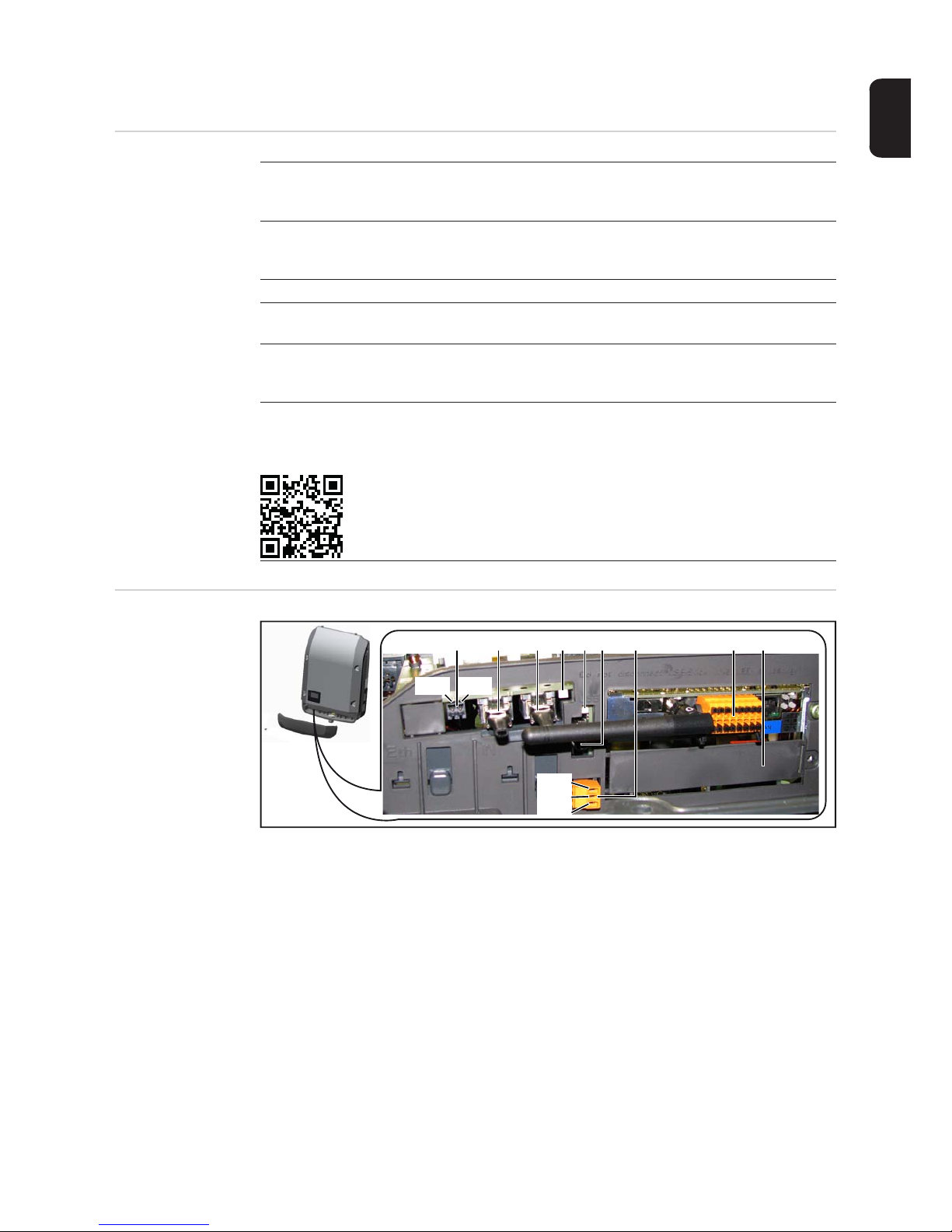
(1) (2) (3) (4)
(5)
(6) (7) (8) (9)
IN
IN
OUT
OUT
PIN 2
PIN 1
PIN 1
PIN 2
PIN 3
Page 14

12
Explanation of
the multifunction
current interface
Various wiring variants can be connected to the multifunction current interface. However,
these cannot be operated simultaneously. For example, if an S0 meter is connected to the
multifunction current interface, it is not possible to connect a signal contact for overvoltage
protection (or vice versa).
Pin 1 = measurement input: max. 20 mA, 100 Ohm measurement resistor (load impedance)
Pin 2 = max. short circuit current 15 mA, max. open circuit voltage 16 V DC or GND
Item Designation
(1) Switchable multifunction current interface. For more details, refer to the section
below entitled "Explanation of the multifunction current interface"
Use the 2-pin mating connector supplied with the inverter to connect to the multifunction current interface.
(2)
(3)
Fronius Solar Net connection / interface protocol IN
Fronius Solar Net connection / interface protocol OUT
'Fronius Solar Net' / interface protocol input and output for connecting to other
DATCOM components (e.g. inverter, sensor box, etc.)
If several DATCOM components are linked together, a terminating plug must be
connected to every free IN or OUT connection on a DATCOM component.
For inverters with a Fronius Datamanager plug-in card, two terminating plugs are
supplied with the inverter.
(4) The 'Solar Net' LED
indicates whether the Fronius Solar Net power supply is available
(5) The 'Data transfer' LED
flashes while the USB flash drive is being accessed. The USB flash drive must
not be removed while recording is in progress.
(6) USB A socket
for connecting a USB flash drive with maximum dimensions of
65 x 30 mm (2.6 x 2.1 in.)
The USB flash drive can function as a datalogger for an inverter. The USB flash
drive is not included in the scope of supply of the inverter.
(7) Floating switch contact with mating connector
max. 250 V AC / 4 A AC
max. 30 V DC / 1 A DC
max. 1.5 mm² (AWG 16) cable cross-section
Pin 1 = NO contact (Normally Open)
Pin 2 = C (Common)
Pin 3 = NC contact (Normally Closed)
Use the mating connector supplied with the inverter to connect to the floating
switch contact.
(8) Fronius Datamanager with WLAN antenna
or
cover for option card compartment
(9) Cover for option card compartment
Page 15
13
EN
Wiring diagram variant 1: Signal contact for overvoltage protection
Depending on the setting in the Basic menu, the DC OVP Typ 2 option (overvoltage protection) either outputs a warning or an error on the display. Further information on the DC
OVP Typ 2 option can be found in the installation instructions.
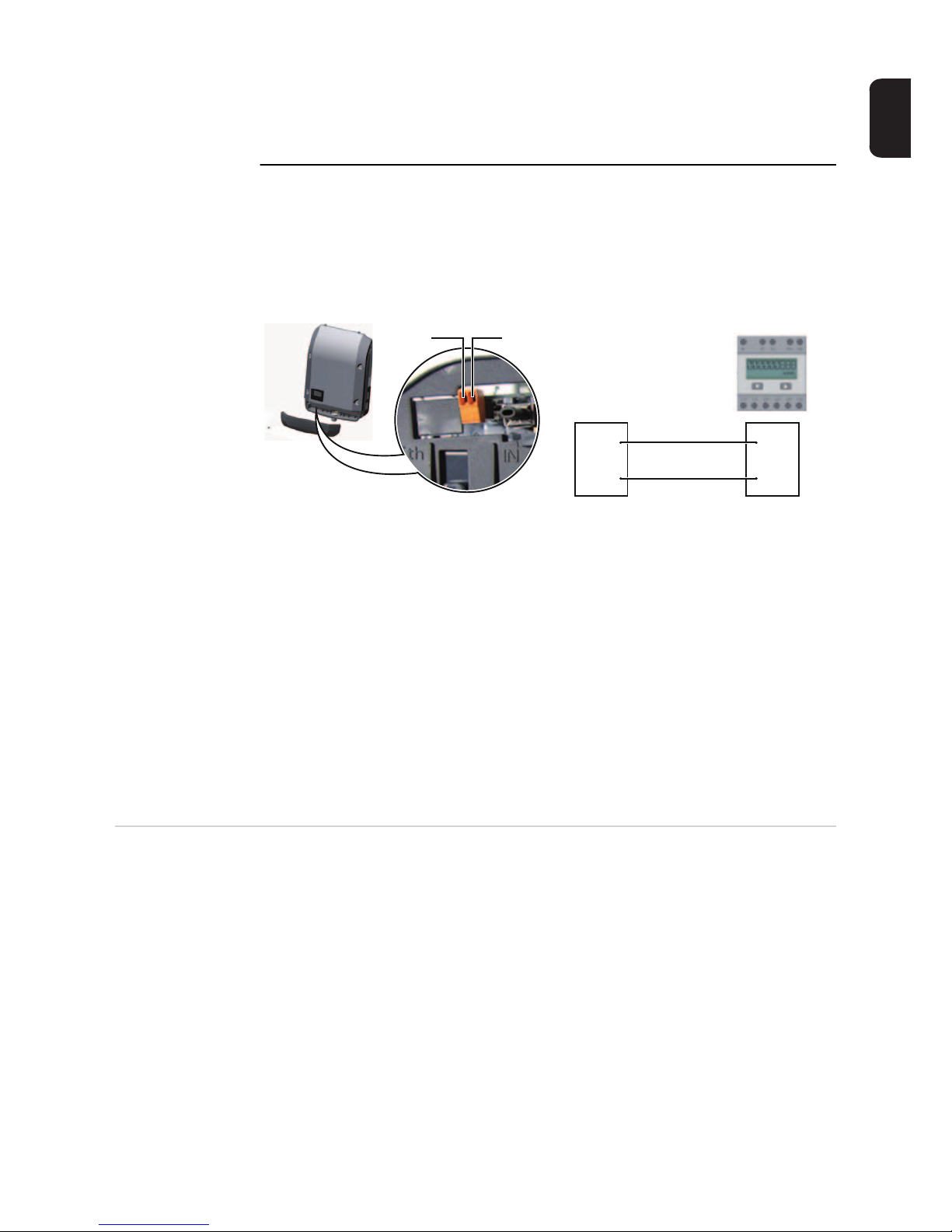
Wiring diagram variant 2: S0 meter
A meter for recording the self-consumption of each S0 can be connected directly to the inverter.
IMPORTANT! In order to connect an S0 meter to the inverter, it may be necessary to update the inverter firmware.
Requirements for the S0 meter:
- Must comply with the IEC62053-31 Class B standard
- Max. voltage 15 V DC
- Max. current when ON 15 mA
- Min. current when ON 2 mA
- Max. current when OFF 0.15 mA
Recommended max. pulse rate of the S0 meter:
Description of the
'Fronius Solar
Net' LED
The 'Solar Net' LED is on:
the power supply for data communication within the Fronius Solar Net / interface protocol
is OK
The 'Solar Net' LED flashes briefly every 5 seconds:
data communication error in the Fronius Solar Net
- Overcurrent (current flow > 3 A, e.g. resulting from a short circuit in the Fronius Solar
Net ring)
- Undervoltage (not a short circuit, voltage in Fronius Solar Net < 6.5 V, e.g. if there are
too many DATCOM components on the Fronius Solar Net and not enough electrical
power is available)
In this case, power for the DATCOM components must be supplied by connecting an
additional power supply to one of the DATCOM components.
To detect the presence of an undervoltage, check some of the other DATCOM components for faults as required.
PV output kWp [kW] Max. pulse rate per kWp
30 1000
30 2000
10 5000
≤ 5.5 10000
Pin 1Pin 2
Pin 1
Pin 2 S0 +
S0 -
Page 16

14
After cutting out because of overcurrent or undervoltage, the inverter attempts to restore
the power supply in the Fronius Solar Net every 5 seconds while the fault is still present.
Once the fault is rectified, power to the Fronius Solar Net will be restored within 5 seconds.
Example Recording and archiving data from the inverter and sensor using a Fronius Datamanager
and a Fronius Sensor Box:
Data network with 3 inverters and a Fronius Sensor Box:
- Inverter 1 with Fronius Datamanager
- Inverters 2 and 3 without Fronius Datamanager!
The external communication (Fronius Solar Net) takes place on the inverter via the data
communication area. The data communication area contains two RS 422 interfaces as inputs and outputs. RJ45 plug connectors are used to make the connection.
IMPORTANT! Since the Fronius Datamanager functions as a data logger, the Fronius Solar Net ring must not include any other data logger.
Only one Fronius Datamanager per Fronius Solar Net ring!
Any other Fronius Datamanagers must be removed and the unoccupied option card compartment sealed off using the blanking cover (42,0405,2020 - available from Fronius as an
optional extra); alternatively, use an inverter without Fronius Datamanager (light version).
Installing option
cards in the inverter
Information on installing option cards in the inverter and connecting the data communication cable can be found in the installation instructions.
= Terminating plug
12
3
IN
OUT
°C
W/m²
m/s
IN
OUT
IN
OUT
Sensor Box
WLAN
* Fronius Datamanager
*
IN OUT
Page 17
15
EN
System monitoring
General Where no special device model is present, the inverter is fitted with WLAN-compatible Fro-
nius Datamanager 2.0 system monitoring as standard.
Among other things, system monitoring includes the following functions:
- Own web page displaying current data and a wide range of different setting options
- Option of connecting directly to Fronius Solar.web
- Automatic sending of service messages by SMS or e-mail in the event of a fault
- Internet connection via WLAN or LAN
- Option of controlling the inverter by specifying power limit values, minimum or maximum running times or target running times
- Control of the inverter via Modbus (tcp / rtu)
- Assignment of control priorities
- Control of the inverter by means of connected meters (Fronius Smart Meter or S0 meter)
- Control of the inverter via a ripple control signal recipient (e.g. specification of reactive
power or effective power)
- Dynamic power reduction, taking self-consumption into account
Further information on Fronius Datamanager 2.0 can be found online in the Fronius Datamanager 2.0 operating instructions.
Fronius Datamanager during the
night or when the
available DC voltage is insufficient
The Night Mode parameter under "Display Settings" in the Setup menu is preset to OFF in
the factory.
For this reason the Fronius Datamanager cannot be accessed during the night or when the
available DC voltage is insufficient.
To nevertheless activate the Fronius Datamanager, switch the inverter off and on again at
the mains and press any key on the inverter display within 90 seconds.
See also the chapters on "The Setup menu items", "Display settings" (Night Mode).
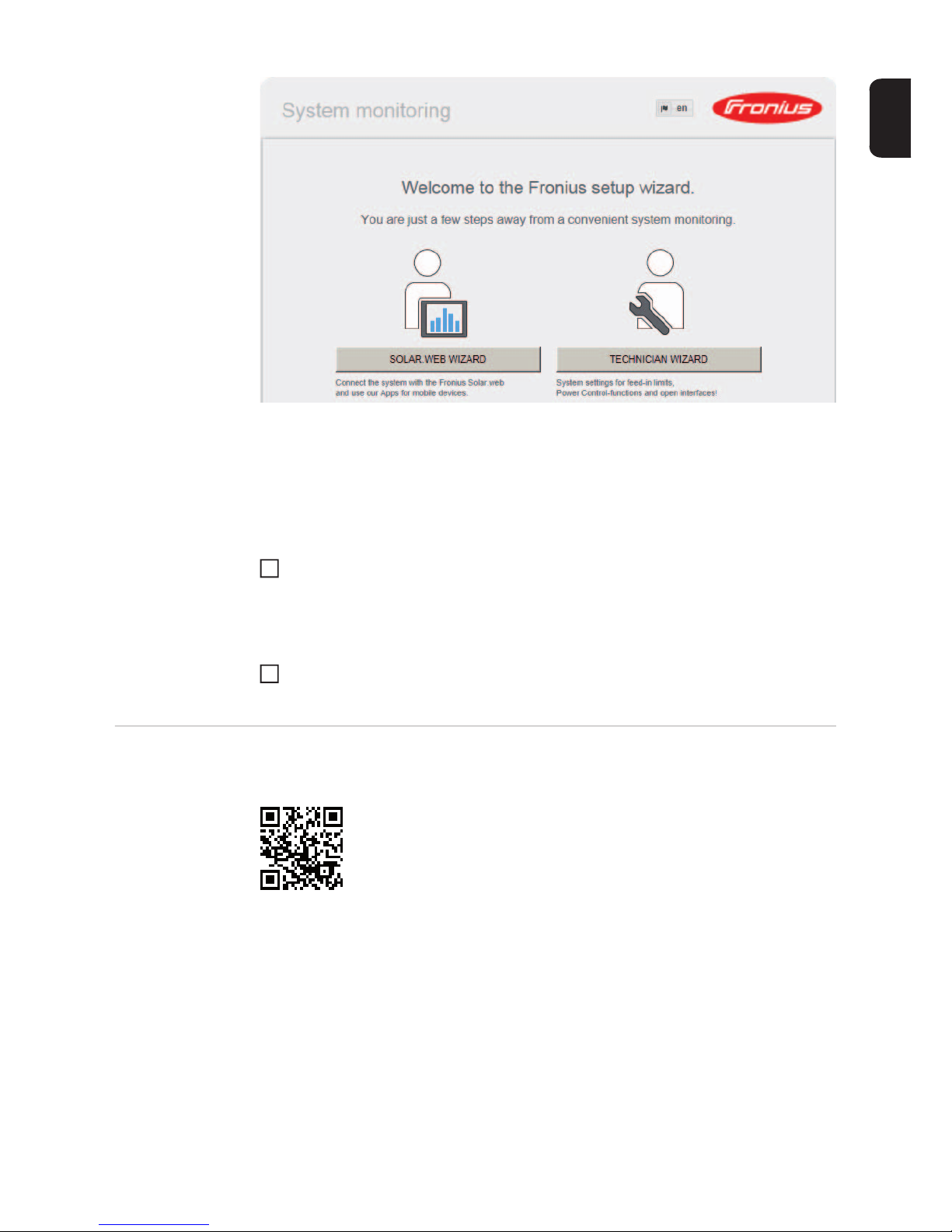
Starting for the
first time
When starting Fronius Datamanager 2.0 for the first time,
- the Fronius Datamanager 2.0 plug-in card must be installed in the inverter,
or
- there must be a Fronius Datamanager Box 2.0 in the Fronius Solar Net ring.
IMPORTANT! In order to establish a connection to Fronius Datamanager 2.0, the end device in question (e.g. laptop, tablet, etc.) must be set up as follows:
- "Obtain IP address automatically (DHCP)" must be activated
NOTE! Starting the Fronius Datamanager 2.0 for the first time can be made significantly easier with the aid of the Fronius Solar.web App.
The Fronius Solar.web App is available in the relevant App store.
NOTE! If the photovoltaic system has only one inverter, steps 1 and 2 below can
be skipped. In this case, starting for the first time will commence with step 3.
Page 18

16
Connect inverter with Fronius Datamanager 2.0 or Fronius Datamanager Box 2.0 to
the Fronius Solar Net
When networking several inverters together in Fronius Solar Net:
Set the Fronius Solar Net master / slave switch on the Fronius Datamanager 2.0 plugin card correctly
- One inverter with Fronius Datamanager 2.0 = master
- All other inverters with Fronius Datamanager 2.0 = slave (the LEDs on the Fronius
Datamanager 2.0 plug-in cards are not illuminated)
Switch the device into service mode
- Activate the WLAN access point via the Setup menu on the inverter
The inverter establishes the WLAN access point. The WLAN access point remains open
for 1 hour.
The Setup wizard start page is displayed.
Installation using the Solar.web App Installation using a web browser
Download the Fronius Solar.web App
Run the Fronius Solar.web App
Connect the end device to the WLAN
access point
SSID = Fronius_240.xxxxx (5-8 digits)
- Search for a network with the
name "Fronius_240.xxxxx"
- Establish a connection to this
network
- Enter password 12345678
(or connect the end device and inverter using an Ethernet cable)
Entry in browser:
http://datamanager
or
192.168.250.181 (IP address for
WLAN connection)
or
169.254.0.180 (IP address for LAN
connection)
1
2
3
Stand by
WiFi Access Point
DATCOM
USB
Clock
4
5
4
5
Page 19
17
EN
The technician wizard is intended for the installer and contains standard-specific settings.
Running the technician wizard is optional.
If the technician wizard is run, it is vital to note the service password that is issued. This
service password is necessary for setting the EVU Editor menu item.
If the technician wizard is not run, no specifications regarding power reduction are set.
Running the Solar Web wizard is mandatory.
Run the Solar Web wizard and follow the instructions
The Fronius Solar.web homepage is displayed,
or
the Fronius Datamanager 2.0 web page is displayed.
Where necessary, run the technician wizard and follow the instructions
Further information on Fronius
Datamanager 2.0
6
7
Further information on the Fronius Datamanager 2.0 and other start-up options can be
found at:
http://www.fronius.com/QR-link/4204260191EA
Page 20
18
Controls and indicators
Controls and indicators
Item Description
(1) Display
showing values, settings and menus
Monitoring and status LEDs
(2) General status LED (red)
on steady,
- if a status message is being displayed on the monitor
- if the process of feeding energy into the grid is interrupted
- while error handling (the inverter waits for an acknowledgement or for an
error to be rectified)
(3) Startup LED (orange)
on steady if
- the inverter is in its automatic startup or self-test phase (as soon after sunrise as the solar modules are delivering sufficient power)
- the inverter has been switched to standby mode in the setup menu (= feeding energy into the grid switched off manually)
- the inverter software is being updated
(4) Operating status LED (green)
on steady,
- if the PV system is working correctly after the inverter's automatic startup
phase
- all the time while energy is being fed into the grid
Function keys - allocated different functions depending on the selection:
(5) 'Left/up' key
for navigating to the left and up
(6) 'Down/right' key
for navigating down and to the right
(7) 'Menu/Esc' key
for switching to the menu level
for quitting the Setup menu
(8) 'Enter' key
for confirming a selection
(1)
(2)
(3)
(4)
(5) (6) (7) (8)
Page 21
19
EN
The keys are capacitive, and any exposure to water can impair their function. Wipe the
keys dry with a cloth if necessary to ensure optimum functionality.
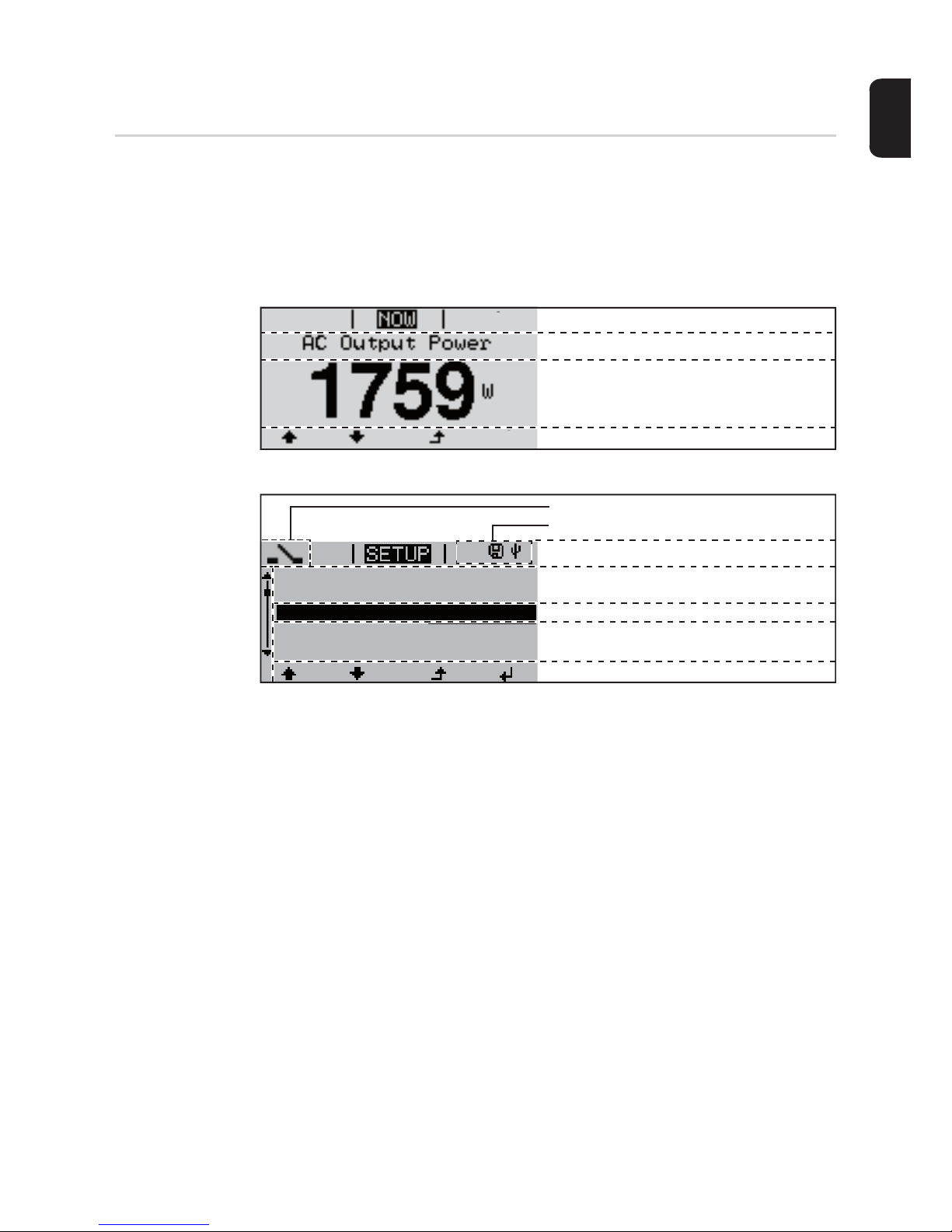
Display Power for the display comes from the mains voltage. Depending on the setting selected in
the Setup menu, the display can be kept on all day.
Display areas in display mode
Display areas in setup mode
(*) Scroll bar
(**) The Energy Manager symbol
is displayed when the Energy Manager function is activated
(***) Inv. no. = Inverter DATCOM number,
Save symbol - appears briefly while set values are being saved,
USB connection - appears if a USB flash drive has been connected
IMPORTANT! The display on the inverter is not a calibrated measuring device. A slight inaccuracy in comparison with the energy meter used by the energy supply company is intrinsic to the system. A calibrated meter will be needed to calculate the bills for the energy
supply company.
Function key functions
Menu item
Parameter declaration
Display of values, units and status codes
Function key functions
Next menu items
Currently selected menu item
Previous menu items
Menu item
Inv. no. | Save symbol | USB conn.(***)
(*)
1
Energy-Manager (**)
Standby
WiFi Access Point
DATCOM
USB
Relay
Page 22

20
The menu level
Activate display
backlighting
Press any key
The display backlighting is activated.
There is an option under 'Display Settings' in the SETUP menu to set the display backlighting so that it is on all the time or off all the time.
Automatic deactivation of display
backlighting /
choose 'NOW'
menu item
If no key is pressed for 2 minutes,
- the display backlighting switches off automatically and the inverter goes to the 'NOW'
menu item (assuming the display backlighting is set to automatic).
- The selection of the 'NOW' menu item can happen from any position on the menu level
with the exception of the item 'Standby' on the Setup menu.
- The amount of energy currently fed in is displayed.
Open menu level
1
Press the 'Menu' key
The display switches to the menu level
Use the 'Left' or 'Right' keys to select
the desired menu item
Press the 'Enter' key to select the desired menu item
1
2
3
Page 23
21
EN
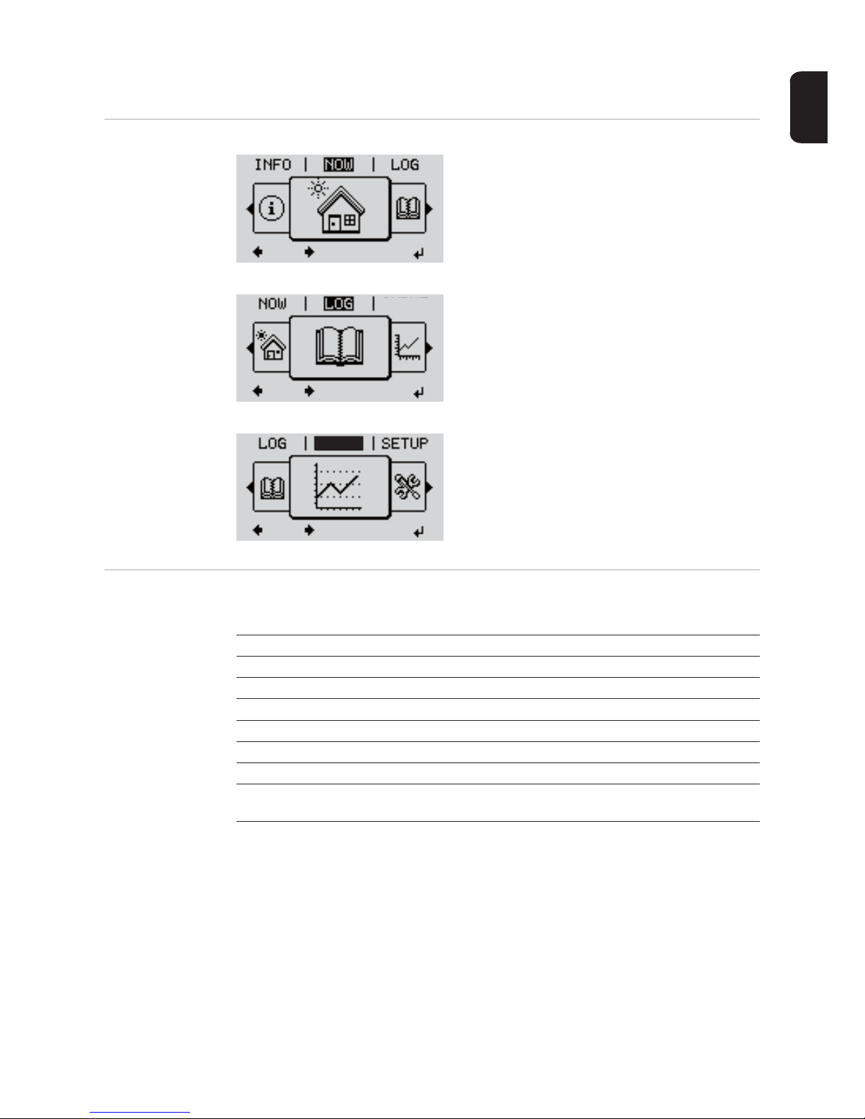
The NOW, LOG and GRAPH menu items
NOW
LOG
GRAPH
Values displayed
in the NOW and
LOG menu items
NOW
(Displays real-time values)
LOG
(Data recorded today, during the current
calendar year and since the inverter was
first commissioned)
GRAPH
Day characteristic
displays a plot showing the power output
during the day. The time axis is scaled automatically.
Press the 'Back' key to remove the display
GRAPH
GRAPH
Values displayed in the NOW menu item:
AC Output power (W)
AC Reactive power (V Ar)
AC Voltage (V)
AC Output current (A)
AC Frequency (Hz)
PV Array Voltage (V)
PV Array Current (A)
Time / date
Time and date on the inverter or in the Fronius Solar Net ring
Page 24

22
Values displayed in the LOG menu item:
(for today, during the current calendar year and since the inverter was started for the first
time)
AC Energy Yield (kWh / MWh)
Energy fed into the grid during the period in question
There may be discrepancies with values displayed on other measuring instruments because of differences in measuring methods. As far as the billing of the energy fed in is
concerned, the only binding display values are those produced by the calibrated measuring device provided by the electricity supply company.
AC Max. Output Power (W)
Largest amount of power fed into the grid during the period in question
Earnings
Amount of money earned during the period in question (currency can be selected in the
Setup menu)
Like the energy supplied figure, the yield figure may also exhibit discrepancies with other
measured values.
The 'Setup Menu' section explains how to select a currency and charge rate.
The factory setting depends on the respective country setup.
CO2 savings (g / kg)
CO2 emissions saved during the period in question
The value for CO2 savings depends on the power station facilities and corresponds to the
CO2 emissions that would be released when generating the same amount of energy. The
factory setting is 0.53 kg / kWh (source: DGS – Deutsche Gesellschaft für Sonnenenergie
e.V. (German Society for Solar Energy).
AC Max. Voltage L-N (V)
Highest voltage measured between the conductor and neutral conductor during the period in question
PV Array Max. Voltage (V)
Highest solar module voltage measured during the period in question
Operating Hours
Length of time the inverter has been working (HH:MM).
IMPORTANT! A prerequisite for the correct display of day and year values is that the time
is set correctly.
Page 25
23
EN
SETUP menu item
Initial setting The inverter is pre-configured and ready to use. There is no need to enter any initial set-
tings before using it to feed energy into the grid, as this is a fully-automated process.
The SETUP menu item allows the initial settings of the inverter to be changed easily to
bring it in line, as closely as possible, with the preferences and requirements of the user.
SETUP
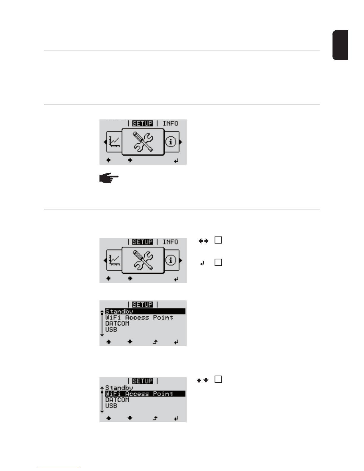
Navigating in the
SETUP menu item
Enter the SETUP menu item
Scrolling between the entries
Exiting an entry
SETUP
(Setup menu)
NOTE! As a result of software updates, you may find that your device has certain
functions that are not described in these operating instructions, or vice versa. Certain illustrations may also differ slightly from the actual controls on your device.
but these controls function in exactly the same way.
GRAPH
Menu level, 'SETUP' selected
In the menu level, use the 'Left' or
'Right' keys to select the 'SETUP'
menu item
Press the 'Enter' key
'Standby' entry
The first entry under the SETUP menu
item is displayed:
'Standby'
Example: 'WiFi Access Point' menu item
Use the 'Up' and 'Down' keys to move
between the available entries
GRAPH
1
2
Relay
Relay
3
Page 26
24
If no key is pressed for 2 minutes,
- The inverter switches from wherever it is on the menu level back to the 'NOW' display
mode (exception: 'Standby' Setup menu entry),
- the display backlighting goes out.
- The amount of energy currently being fed in is displayed.
Setting entries on
the Setup menu,
general
Enter the SETUP menu item
Use the 'Up' or 'Down' keys to select the desired menu item
Press 'Enter'
To exit a menu entry, press the 'Back'
key
The menu level appears
GRAPH
4
The first digit of a value to be set flashes:
The available settings are displayed:
Use the 'Up' or 'Down' keys to select
a value for the first digit
Press 'Enter'
The second digit of the value flashes.
Repeat steps 4 and 5 until ...
the whole value to be set flashes.
Press 'Enter'
Repeat steps 4 - 6 as required for
units or other values that are to be set
until the appropriate unit or the value
flashes.
Press the 'Enter' key to save and apply the changes.
To discard the changes, press the
'Esc' key.
Use the 'Up' or 'Down' keys to select
the desired setting
Press the 'Enter' key to save and apply the setting.
To discard the setting, press the 'Esc'
key.
The currently selected menu item is displayed.
The currently selected menu item is displayed.
1
2
3
4
5
6
7
8
9
4
5
Page 27
25
EN
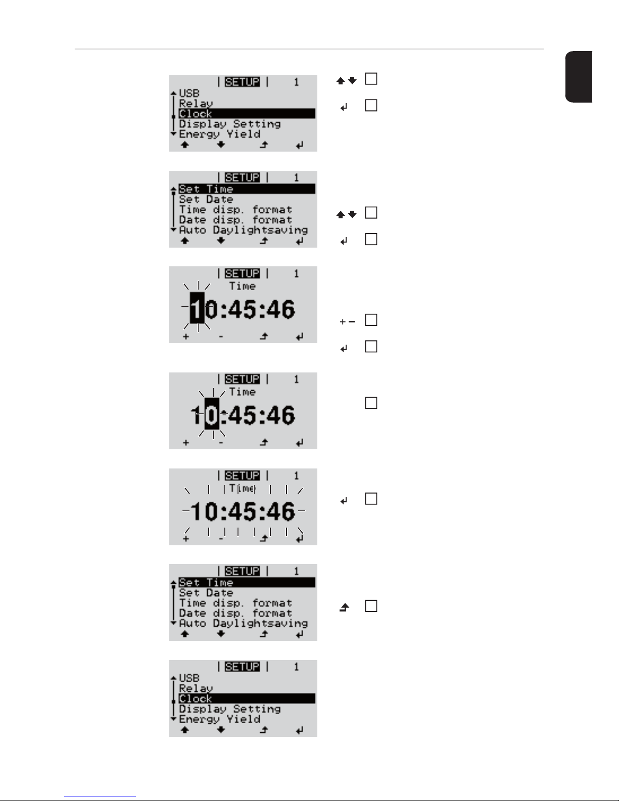
Application example: Setting
the time
Select 'Time / Date' from the Setup
menu
Press the 'Enter' key
An overview of the values that can be
changed is displayed.
Use the 'Up' or 'Down' keys to select
'Set time'
Press the 'Enter' key
The current time appears.
(HH:MM:SS, 24-hour clock),
the 'tens' digit for the hour will flash.
Use the 'Up' and 'Down' keys to select
a value for the 'tens' digit for the hour
Press the 'Enter' key
The 'units' digit for the hour will flash.
Repeat steps 5 and 6 for the 'units'
digit for the hour, for the minutes and
seconds until...
the set time starts flashing.
Press the 'Enter' key
The time is applied and the overview of
values that can be changed is displayed.
Press the 'Esc' key
The 'Time / Date' item on the Setup menu
appears.
1
2
3
4
5
6
7
8
4
Page 28
26
The Setup menu items
Standby Manual activation / deactivation of Standby mode
- No energy is fed into the grid.
- The Startup LED will show steady orange.
- In Standby mode, no other menu item at menu level can be accessed or adjusted.
- The automatic switchover into the 'NOW' display mode after 2 minutes of keyboard inactivity does not occur.
- Standby mode can only be terminated manually by pressing the 'Enter' key.
- Feeding energy into the grid can be resumed at any time (deactivate 'Standby').
Switching off Standby mode (manually switching off feeding energy into the grid):
Select the 'Standby' item
Press the 'Enter' key
'STANDBY' and 'ENTER' appear alternately on the display.
Standby mode is now active.
The Startup LED shows steady orange.
Resuming feeding energy into the grid:
'STANDBY' and 'ENTER' appear alternately on the display when in Standby mode.
Press the 'Enter' key to resume feeding energy into the grid
The 'Standby' menu item is displayed.
At the same time, the inverter enters the startup phase.
The operating state LED shows steady green when feeding energy into the grid has been
resumed.
WiFi Access
Point
For activating / deactivating the WLAN access point (e.g. to set up system monitoring)
1
2
1
Setting range WiFi Access Point
[stopped]
Activate WiFi AP?
To activate the WLAN access point Press the 'Enter' key
WiFi Access Point
[active]
The SS-ID (SS) and password (PW) are displayed.
Deactivate WiFi AP?
To deactivate the WLAN access point Press the 'Enter'
key
Page 29

27
EN
DATCOM Checking data communications, entering the inverter number, DATCOM night mode, pro-
tocol settings
Status
Indicates data communication is taking place via a Fronius Solar Net or that a data communications error has occurred
Inverter number
Sets the number (= address) of the inverter in a system with several solar inverters
Protocol type
Specifies the communications protocol to be used to transfer the data:
* The protocol type 'interface protocol' only functions when there is no Datamanager card
in the inverter. All Datamanager cards must be removed from the inverter.
USB Specification of values in conjunction with a USB stick
Safely remove hardware
To remove a USB stick from the USB A socket on the plug-in data communications card
without losing any data.
The USB stick can be removed:
- when the OK message appears
- when the 'Data transfer' LED stops flashing or comes on steady
Software Update
To update the inverter software via a USB stick.
Procedure:
Download the relevant update file 'froxxxxx.upd'
(e.g. from http://www.fronius.com; xxxxx stands for the version number)
***
WiFi Access Point
[not available]
Displayed if there is no system monitoring present on the inverter.
Setting range Status / inverter number / protocol type
Setting range 00 - 99 (00 = 100th inverter)
Factory setting 01
IMPORTANT! If a number of inverters are linked together in a data communications system, assign a unique address to each one.
Setting range Fronius Solar Net / interface protocol *
Factory setting Fronius Solar Net
Setting range Safely remove hardware / Software update / Logging interval
1
Page 30

28
Save the update file to the highest data level of the USB stick
Open the data communication area
Plug the USB stick containing the update file into the USB socket in the data commu-
nication area
Select 'USB' from the Setup menu, followed by 'Update software'
Press the 'Enter' key
Wait until the version currently installed on the inverter and the new software version
are displayed for comparison:
- 1st page: Recerbo software (LCD), key controller software (KEY), country setup
version (Set)
- 2nd page: Power stage set software
Press the 'Enter' key after each page
The inverter starts copying the data.
'UPDATE' and the progress of storing the individual tests expressed in % are displayed until all the data for all the electronic modules has been copied.
Once copying is complete, the inverter updates the electronic modules as required in sequence.
'UPDATE', the affected modules and the update progress in % are displayed.
The final step is for the inverter to update the display.
The display remains dark for approx. 1 minute while the monitoring and status LEDs flash.
Once the software update is complete, the inverter enters its startup phase before going
on to start feeding energy into the grid. The USB stick can be unplugged.
When the inverter software is updated, any custom settings that were configured in the
Setup menu are retained.
IMPORTANT! In order for the logging function to work correctly the time must be set correctly.
NOTE! To successfully update the inverter software, the USB stick provided for
the purpose must not have a hidden partition or any encryption (see chapter "Suitable USB sticks").
Logging interval
Activate / deactivate the logging function and specify a logging interval
Unit Minutes
Setting range 30 min. / 20 min./ 15 min./ 10 min./ 5 min./ No log
Factory setting 30 min.
30 min. The logging interval is 30 minutes; every 30 minutes new log-
ging data will be saved on the USB stick.
20 min.
15 min.
10 min.
5 min. The logging interval is 5 minutes; every 5 minutes new logging
data will be saved on the USB stick.
No log No data is saved
2
3
4
5
6
7
8
Page 31

29
EN
Relay Activate relay, relay settings, relay test
* these are only shown if the 'E-Manager' function has been activated under 'Relay mode'.
Relay mode
for selecting the different functions of the floating switch contact in the data communication
area:
- Alarm function
- Active output
- Energy-Manager
Relay test
Function test to determine whether the floating switch contact switches
Switch-on point (only if 'Energy-Manager' function is activated)
for setting the effective power limit beyond which the floating switch contact is switched on
Switch-off point (only if 'Energy-Manager' function is activated)
for setting the effective power limit beyond which the floating switch contact is switched off
Energy-Manager
(in Relay menu
item)
The 'Energy-Manager' function can be used to activate the floating switch contact in such
a way that it functions as an actuator.
Thus a consumer that is connected to the floating switch contact can be controlled by specifying a switch-on or switch-off point that depends on the feed-in power.
Setting range Relay mode / Relay test / Switch-on point* / Switch-off point*
Setting range ALL / Permanent / OFF / ON / E-Manager
Factory setting ALL
Alarm function:
Permanent /
ALL:
Switch the floating switch contact for permanent and temporary service codes (e.g. brief interruption to energy being fed into the grid, a
service code occurs a certain number of times a day - can be adjusted
in 'BASIC' menu)
Active output:
ON: The floating NO contact is on all the time the inverter is in operation
(as long as the display is not dark and is displaying something).
OFF: The floating NO contact is off.
Energy-Manager:
E-Manager: Further details on the 'Energy-Manager' function may be found in the
"Energy-Manager" section.
Factory setting 1000 W
Setting range Switch-off point - max. nominal output of inverter / W / kW
Factory setting 500
Setting range 0 - Switch-on point / W / kW
Page 32

30
The floating switch contact is automatically switched off,
- if the inverter is not feeding any power into the grid,
- if the inverter is manually switched into standby mode,
- if the effective power is < 10% of nominal output,
- in the event of insufficient insolation.
To deactivate the 'Energy-Manager' function, select a different function and press the 'Enter' key.
Notes on setting up the switch-on and switch-off points
If the difference between the switch-on and switch-off points is too small, or if there are fluctuations in effective power, the result may be multiple switching cycles.
To avoid switching on and off frequently, the difference between the switch-on and switchoff points should be at least 100 - 200 W.
When choosing the switch-off point the power consumption of the connected consumer
should be taken into account.
When choosing the switch-on point, the weather conditions and anticipated insolation
should also be taken into account.
Application example
Switch-on point = 2000 W, switch-off point = 1800 W
If the inverter is outputting 2000 W or above, then the floating switch contact on the inverter
is switched on.
If the inverter output falls to below 1800 W, the floating switch contact is switched off.
Possible applications:
operating a heat pump or an air-conditioning system using as much self-generated power
as possible
Time / date Set the time, date and automatic changeover between summer and winter time
Set time
Set the time (hh:mm:ss or hh:mm am/pm - depending on the setting in the time display format)
Set date
Set the date (dd.mm.yyyy or mm/dd/yyyy - depending on the setting in the date display format)
To activate the 'Energy-Manager' function, select 'E-Manager' and press the 'Enter' key.
When the 'Energy-Manager' function is running, the 'Energy-Manager' symbol will appear
in the top left corner of the display:
when the floating NO contact is off (open contact)
when the floating NO contact is on (closed contact)
Setting range Set time / set date / time display format / date display format /
summer/winter time
Time display format
for specifying the time display format
Page 33

31
EN
Summer/winter time
Activate / deactivate automatic changeover between summer and winter time
IMPORTANT! The correct time and date is a prerequisite for the correct display of day and
year values and the day characteristic.
Display settings
Language
Set language for display
Night mode
DATCOM night mode; controls the DATCOM and display operation during the night or
when the DC voltage is insufficient
Setting range 12hrs / 24hrs
Factory setting Depends on country setup
Date display format
for specifying the date display format
Setting range mm/dd/yyyy / dd.mm.yy
Factory setting Depends on country setup
NOTE! Only use the automatic summer/winter time changeover function if the
Fronius Solar Net ring does not include any LAN- or WLAN-compatible system
components (e.g. Fronius Datalogger Web, Fronius Datamanager or Fronius Hybridmanager).
If it does include such system components, then this function should be switched
on using the system component's web interface.
Setting range on / off
Factory setting on
Setting range Language / Night mode / Contrast / Lighting
Setting range German, English, French, Dutch, Italian, Spanish, Czech, Slo-
vak, etc.
Setting range AUTO / ON / OFF
Factory setting OFF
AUTO: DATCOM mode is always in effect as long as there is a Datalogger connect-
ed in an active and uninterrupted Fronius Solar Net.
The display remains dark during the night, but can be activated by pressing
any key.
Page 34

32
Contrast
Set the contrast on the display
Since the contrast is temperature-dependent, when the ambient conditions change it may
be necessary to adjust the 'Contrast' menu item.
Illumination
Initial setting for display illumination
The 'Illumination' menu item only relates to the display backlighting.
Energy yield Setting
- of an OFFSET value for the total energy display
- of a measuring offset factor for the day, year and total energy display
- of the currency
- of the feed-in tariff
ON: DATCOM mode is always in effect. The inverter supplies 12 V continuously
to power the Fronius Solar Net. The display is always active.
IMPORTANT! If DATCOM night mode is set to ON or AUTO when there are
Fronius Solar Net components connected, then the inverter's current consumption during the night will increase to around 7 W.
OFF: DATCOM will not run at night, the inverter will not need any AC current in
order to supply power to the Fronius Solar Net.
The display is switched off during the night and the Fronius Datamanager is
not available.
Setting range 0 - 10
Factory setting 5
Setting range AUTO / ON / OFF
Factory setting AUTO
AUTO: Display backlighting is activated by pressing any key. If no key is pressed for
2 minutes, the display backlighting will go off again.
ON: The display backlighting remains permanently on when the inverter is
switched on.
OFF: The display backlighting is permanently switched off.
Setting range Meter deviation / Meter calibration / Currency / Feed-in tariff
Meter deviation
Input of a value for the fed-in energy that will be added to the energy currently fed in (e.g.
carry-over value when replacing an inverter)
Unit Wh / kWh / MWh
Setting range Five digits
Factory setting 0
Page 35

33
EN
Fan To check that the fan is working correctly
- Use the 'Up' and 'Down' keys to select the desired fan
- Testing of the selected fan is initiated by clicking 'Enter'.
- The fan will continue to run until the operator exits the menu by pressing 'Esc'.
Meter calibration
Input of a correction value to ensure that the value shown on the inverter display corresponds with the calibrated display on the electricity meter
Unit %
Setting range -5.0 - +5.0
Factory setting 0
Currency
Set the currency
Setting range 3 characters, A-Z
Feed-in tariff
Set the remuneration rate for energy fed into the grid
Setting range 2 digits, 3 decimal places
Factory setting (depends on country setup)
Setting range Test fan #1 / Test fan #2 (depending on the device)
Page 36

34
The INFO menu item
INFO
Measured values
PSS status
Grid status
Device information
For displaying the settings that will be of relevance to an energy supply company. The values shown will depend on the country setup or the device-specific settings of the inverter.
INFO
(Information about the device and the software)
Measured values Display range: PV ins. / Ext. lim. / U PV1 / GVDPR / Fan
#1
PV Iso.
Insulation resistance of the PV system (with ungrounded solar modules and solar modules with negative pole grounding)
Ext. lim.
External power reduction in percent e.g. specified by grid operator
U PV1
Current DC voltage on the terminals, even if the inverter is not feeding
any power into the grid whatsoever (from the 1st MPP tracker)
GVDPR
Grid voltage-dependent power reduction
Fan #1
Percentage of target output for fan
PSS status The status of the most recent inverter fault can be displayed.
IMPORTANT! Due to the low level of insolation early in the morning
and in the evening, the status codes 306 (Power low) and 307 (DC
low) are displayed routinely at these times of day. These status codes
do not indicate any kind of fault.
- Press the 'Enter' key to see the status of the power stage set and
the most recent fault
- Use the 'Up' and 'Down' keys to scroll through the list
- Press the 'Back' key to close the status and fault list
Grid status The five most recent grid faults can be displayed:
- Press the 'Enter' key to see the five most recent grid faults
- Use the 'Up' and 'Down' keys to scroll through the list
- Press the 'Back' key to close the grid fault display
Page 37

35
EN
Display range General / Country-specific setting / MPP tracker / Grid monitor-
ing / Grid voltage limits / Grid frequency limits / Q-mode / AC
power limit / AC voltage derating / Fault Ride Through
General: Device type
Fam.
Country-specific setting:
Setup
Specified country setup
Version
Version of country setup
Group
Group for updating the inverter software
MPP Tracker: Tracker 1
Monitoring the grid: GMTi
Startup time of inverter in s
GMTr
Reconnection time in s following a grid fault
ULL
Mean grid voltage over 10 minutes in V.
LLTrip
Trip time for long-term voltage monitoring
Grid voltage limits: UILmax
Upper inner grid voltage in V
UILmin
Lower inner grid voltage in V
Grid frequency limits: FILmax
Upper inner grid frequency in Hz
FILmin
Lower inner grid frequency in Hz
Q-mode: current power factor setting cos phi
(e.g. Constant Cos(phi) / Constant Q / Q(U)-characteristic / etc.)
AC power limit: Max. P AC
manual power reduction
Page 38

36
Version Displays the version and serial numbers of the PC boards in the inverter (e.g. for service
purposes)
AC voltage derating: Status
ON / OFF voltage-dependent power reduction
GVDPRe
Threshold from which the voltage-dependent power reduction
begins
GVDPRv
Reduction gradient used to reduce the power, e.g.: 10% per volt
above the GVDPRe threshold.
Message
Activates the dispatch of an info message via Fronius Solar Net
Fault Ride Through: Status - default setting: OFF
If the function is activated, the inverter does not switch off im-
mediately in the event of a short-term AC voltage interruption
(outside of the limits specified by the grid supplier), but instead
continues to feed in power for a defined period.
DB min - default setting: 90%
"Dead Band Minimum" setting in percent
DB max - default setting: 120%
"Dead Band Maximum" setting in percent
k-Fac. - default setting: 0
Display area Display / Display Software / Integrity Checksum / Memory Card
/ Memory Card #1 / Power Stage / Power Stage Software / EMI
Filter / Power Stage #3 / Power Stage #4
Page 39

37
EN
Switching the key lock on and off
General The inverter has a key lock function.
When the key lock is active, the Setup menu is not accessible, i.e. the setup data cannot
be changed accidentally (or maliciously).
The code 12321 has to be entered in order to activate / deactivate the key lock.
Switching the key
lock on and off
Press the 'Menu' key
The menu level appears.
Press the unassigned 'Menu / Esc'
key
5 times
"Access Code" is displayed in the "CODE"
menu; the first digit starts flashing.
Enter the code 12321: use the 'Up'
and 'Down' keys to select a value for
the first digit of the code.
Press the 'Enter' key
The second digit starts flashing.
Repeat steps 3 and 4 for the second,
third, fourth and fifth digit of the access code until ...
the selected code starts flashing.
Press the 'Enter' key
'Key Lock' is displayed in the 'LOCK'
menu.
Use the 'Up' and 'Down' keys to turn
the key lock on or off:
ON = key lock is on (the Setup menu
is not accessible)
OFF = key lock is off (the Setup menu
is accessible)
Press the 'Enter' key
1
2
3
4
Acess Code
5
6
7
8
Page 40

38
USB Stick as a Data Logger and for Updating Inverter Software
USB stick as a datalogger
If a USB stick is connected to the USB A socket it can function as a datalogger for an inverter.
At any time, the logging data stored on the USB stick can be
- imported into the Fronius Solar.access software using the FLD file that was logged at
the same time,
- viewed directly in third-party programs (e.g. Microsoft® Excel) using the CSV file
logged at the same time.
Older versions (before Excel 2007) are limited to a maximum of 65,536 rows.
Suitable USB
flash drives
Due to the variety of USB flash drives available on the market, it cannot be guaranteed that
every USB flash drive will be detected by the inverter.
Fronius recommends that only certified USB flash drives suitable for building sites are used
(look out for the USB-IF logo).
The inverter supports USB flash drives with the following file systems:
- FAT12
- FAT16
- FAT32
Fronius recommends that the USB flash drives employed should only be used for recording logging data or updating the inverter software. The USB flash drives should not contain
any other data.
Further information on "Data on a USB stick", "Data volume and storage capacity" as well
as "Buffer memory" can be found at:
http://www.fronius.com/QR-link/4204260171EN
Page 41

39
EN
USB stick for updating the inverter software
With the help of the USB stick, end customers can also update the inverter software via the
USB item on the SETUP menu: the update file is first saved to the USB stick, from where
it is then transferred to the inverter. The update file must be saved in the root directory on
the USB stick.
Remove USB
stick
USB symbol on the inverter display, e.g. in display mode 'NOW':
If the inverter detects a USB flash drive,
the USB symbol will appear in the top right
corner of the display.
When inserting a USB flash drive, check
whether the USB symbol is displayed (it
may also flash).
NOTE! Please note for outdoor applications that conventional USB flash drives
are often only guaranteed to work within a restricted temperature range. For outdoor applications ensure that the USB flash drive also functions, for example, at
low temperatures.
AC Output Power
NOW
Security note concerning the removal of a USB stick:
IMPORTANT! To avoid any loss of data, a
USB stick may only be removed if the following conditions are met:
- only remove a USB stick via the
'Safely remove USB / HW' item on the
SETUP menu
- the 'Data transmission' LED has
stopped flashing or comes on steady.
Do not disconnect
USB-Stick
while LED is flashing!
X
Page 42

40
The Basic menu
General The Basic menu is used to set the following parameters, which are important for installing
and operating the inverter:
Access the Basic
menu
- DC operating mode
- Fixed voltage
- MPPT1 initial voltage
- USB logbook
- Insulation settings
- TOTAL reset
- Event counter
Press the 'Menu' key
The menu level appears.
Press the unassigned 'Menu / Esc'
key
5 times
"Access Code" is displayed in the "CODE"
menu; the first digit starts flashing.
Enter the code 22742: Use the 'Up'
and 'Down' keys to select a value for
the first digit of the code
Press the 'Enter' key
The second digit starts flashing.
Repeat steps 3 and 4 for the second,
third, fourth and fifth digit of the access code until ...
the selected code starts flashing.
Press the 'Enter' key
The Basic menu appears.
Use the 'Up' or 'Down' keys to select
the desired menu item
Press the 'Enter' key to open the desired menu item
Press the 'Esc' key to exit the Basic
menu
1
2
3
4
Access Code
5
6
MPP Tracker 1
USB Eventlog
Input signal
SMS / Relay
Grounding Settings
7
8
9
Page 43

41
EN
Items on the Basic menu
The Basic menu contains the following items:
MPP Tracker 1
- DC operating mode:
MPP AUTO
FIX
MPP USER
- Fixed voltage:
for inputting a fixed voltage, 120 - 440 V
- MPPT1 initial voltage:
for inputting the MPPT1 initial voltage, 120 - 440 V
USB log book
Activates or deactivates the function for saving all error messages to a USB flash drive
AUTO / OFF / ON
Input signal
- How it works:
Ext Sig. / S0 meter / OFF
- Triggering method (with "Ext. Sig." mode of operation):
Warning / Ext. Stop
- Connection type (with "Ext. Sig." mode of operation):
N/C / N/O
SMS / relay
- Event delay
for inputting the time delay after which an SMS is sent or the relay is to switch
900 - 86,400 seconds
- Event counter:
for entering the number of errors after which an SMS is sent or the relay is to switch:
10 - 255
Grounding setting
- Grounding mode:
Off / Positive / Negative
- Ground monitoring:
Off / Warn Err / Error / Warning
Insulation mode
- Insulation warning:
for activating and deactivating insulation monitoring, with display of a warning without
interruption of feed-in if there is an insulation fault
ON / OFF (depends on the country setup)
- Threshold warning:
for setting an insulation threshold at which the inverter produces a warning (without
interruption of feed-in)
0 - 1000 kOhm (depends on the country setup)
Page 44

42
- Insulation fault:
for activating and deactivating insulation monitoring, with error message and immediate shutdown of the inverter if there is an insulation fault
ON / OFF (depends on the country setup)
- Threshold error:
for setting an insulation threshold at which the inverter produces an error message
and interrupts the feeding of energy into the grid
0 - 1000 kOhm (depends on the country setup)
Temperature warning
for activating / deactivating the overtemperature warning for each event;
the overtemperature warning is sent and displayed on the monitor.
ON / OFF
TOTAL Reset
in the LOG menu item, resets the max. and min. voltage values and the max. power of
feeding in to zero.
Once values have been reset, this action cannot be undone.
To reset the values to zero, press the 'Enter' key.
"CONFIRM" is displayed.
Press 'Enter' again.
The values are reset and the menu is displayed
Page 45

43
EN
Status diagnostics and troubleshooting
Displaying status
codes
The inverter performs a system self diagnosis that automatically detects many faults that
may occur and shows them on the display. This means you are promptly made aware of
malfunctions in the inverter and the photovoltaic system, or of any installation or operating
faults.
If the system self diagnosis has detected a specific fault, the associated status code will be
shown on the display.
Total failure of the
display
If the display fails to come on some time after sunrise:
- Check the AC voltage ON the inverter connections:
the AC voltage must be 230 V (+ 10 % / - 5 %)*.
* The mains voltage tolerance depends on the country setup
Class 1 status
codes
Class 1 status codes generally only arise momentarily and are caused by the public grid.
The initial response of the inverter in this case is to disconnect itself from the grid. The grid
is subsequently checked for the stipulated monitoring period. If no further problem has
been detected by the end of this period, then the inverter will resume feeding energy into
the grid.
The GPIS SoftStart function is activated according to the country setup:
after cutting out due to an AC error, the output power of the inverter is continuously increased by 10% every minute in line with the VDE-AR-N 4105 guideline.
IMPORTANT! Status codes may sometimes appear briefly as a result of the inverter's control response. If the inverter then continues working with no sign of any problem, this
means that there was no fault.
Code Description Behaviour Remedy
102 AC voltage too high
Following careful testing and
when the grid conditions are
within the permissible range
again, the inverter will resume
feeding energy into the grid.
Check grid connections:
If this status code keeps recurring, contact your system engineer
103 AC voltage too low
105 AC frequency too high
106 AC frequency too low
107 AC grid outside the permissible
limits
108 Stand alone operation detect-
ed
Page 46

44
Class 3 status
codes
Class 3 includes status codes that may occur while feeding energy into the grid, but generally do not cause the process to be interrupted for any length of time.
The inverter disconnects automatically from the grid, the grid is then monitored as specified
and the inverter attempts to resume feeding energy into the grid.
Class 4 status
codes
Some of the class 4 status codes necessitate intervention by a Fronius-trained service engineer.
Code Description Behaviour Remedy
301 Overcurrent (AC)
Short-term interruption while
feeding energy into the grid
due to overcurrent in the inverter
The inverter resumes with its
startup routine.
Fault is rectified automatically;
if this status code is displayed
all the time: notify a Froniustrained service engineer.
302 Overcurrent (DC)
303
Power stage set overtemperature
Short-term interruption while
feeding energy into the grid
due to overtemperature
The inverter resumes with its
startup routine.
Purge openings for cooling air
and heat sink if necessary;
fault is rectified automatically;
if this status code keeps recurring, contact your system engineer
304 Internal temperature too high
306
LOW PV OUTPUT
Intermediate circuit voltage
too low for feeding energy into
the grid
Short-term interruption while
feeding energy into the grid
The inverter resumes with its
startup routine.
Fault is rectified automatically;
if this status code occurs when
there is sufficient insolation,
contact your system engineer
307
LOW PV VOLTAGE
DC input voltage too low for
feeding energy into the grid
IMPORTANT! Due to the low level of insolation early in the morning and in the evening, the status codes 306
(LOW PV OUTPUT) and 307 (LOW PV VOLTAGE) are displayed routinely at these times of day. These status
codes do not indicate any kind of fault.
308 Intermediate circuit overvolt-
age
Short-term interruption while
feeding energy into the grid
The inverter resumes with its
startup routine.
Fault is rectified automatically;
if this status code is displayed
all the time: notify a Froniustrained service engineer.
309 DC input voltage too high
Code Description Behaviour Remedy
401
No communication with power
stage set possible
The inverter will automatically
attempt to connect again and,
if possible, will resume feeding
energy into the grid
If the status code is displayed
all the time: notify a Froniustrained service engineer
406
Power stage set temperature
sensor faulty
407
Internal temperature sensor
faulty
408
DC feeding into the grid detected
Page 47

45
EN
Class 5 status
codes
Class 5 status codes do not generally prevent the feeding of energy into the grid, but can
restrict it. These status code are displayed until they are acknowledged by pressing a key
(the inverter, however, continues to operate normally in the background).
412
Fixed voltage mode has been
selected instead of MPP voltage mode and the fixed voltage has been set to too low or
too high a value.
-
If this status code keeps recurring, contact your system engineer
415
Safety cut-out via option card
or RECERBO has triggered
The inverter is not feeding any
energy into the grid.
If the status code is displayed
all the time: notify a Froniustrained service engineer
416
No communication possible
between power stage set and
control system.
The inverter will automatically
attempt to connect again and,
if possible, will resume feeding
energy into the grid
425
No communication possible
with the power stage set
445 Invalid limit value settings
The inverter is not feeding any
energy into the grid for safety
reasons.
Update the inverter firmware;
If the status code is displayed
all the time: notify a Froniustrained service engineer
452
Communication error between
the processors
The inverter will automatically
attempt to connect again and,
if possible, will resume feeding
energy into the grid
If the status code is displayed
all the time: notify a Froniustrained service engineer
453 Short-term grid voltage error
454 Short-term grid frequency error
457 Grid relay sticking
The inverter is not feeding any
energy into the grid.
notify a Fronius-trained service
engineer
459
Error when recording the
measuring signal for the insulation test
460
Reference voltage source for
the digital signal processor
(DSP) is working out of tolerance
472
Fuse for solar module ground
is faulty
The inverter is not feeding any
energy into the grid.
Replace fuse for solar module
ground;
if this status code keeps recurring, contact your system engineer
475
Solar module ground, insulation fault (connection between
solar module and ground)
The inverter is not feeding any
energy into the grid.
If this status code keeps recurring, contact your system engineer
482 Start-up incomplete
The inverter is not feeding any
energy into the grid.
Perform AC reset (turn automatic circuit breaker off and
on), complete start-up
Code Description Behaviour Remedy
Page 48

46
Class 6 status
codes
Some of the class 6 status codes necessitate intervention by a Fronius-trained service engineer.
Code Description Behaviour Remedy
502
Insulation error on the solar
modules
Warning message is shown on
the display
If this status code keeps recurring, contact your system engineer
509
No energy fed into the grid in
the past 24 hours
Warning message is shown on
the display
Acknowledge status code;
Check whether all the conditions for the problem-free feeding of energy into the grid have
been met (e.g. are the solar
modules covered with snow?)
If the status code is displayed
all the time: look out for further
status codes
517
Derating caused by too high a
temperature
When power derating occurs, a
warning message is shown on
the display
Purge cooling air openings and
heat sink if necessary;
fault is rectified automatically;
if this status code keeps recurring, contact your system engineer
551
Fuse for solar module ground
is faulty
Warning is shown on the display
Replace fuse for solar module
ground;
if this status code keeps recurring, contact your system engineer
558
Functional incompatibility (one
or more PC boards in the inverter are not compatible with
each other, e.g. after a PC
board has been replaced)
Possible error displays or malfunctions on the inverter
If this status code keeps recurring, contact your system engineer
560
Derating caused by overfrequency
This status code is displayed
when the grid frequency becomes excessively high.
The inverter will then reduce its
output.
The status indicator will continue to be displayed until the inverter has returned to normal
operation.
As soon as the grid frequency
is back within the permissible
range and the inverter has returned to normal operation, the
fault is rectified automatically.
If this status code keeps recurring, contact your system engineer.
568
Incorrect input signal on the
multifunction current interface
The status code is displayed in
the case of an incorrect input
signal on the multifunction current interface and with the following setting:
Basic menu / Input signal /
Mode of operation = Ext. Signal, triggering method = Warning
Acknowledge status code;
check the devices connected
to the multifunction current interface;
if this status code keeps recurring, contact your system engineer.
Page 49

47
EN
Class 7 status
codes
Class 7 status codes relate to the control system, the configuration and inverter data recording, and may directly or indirectly affect the process of feeding energy into the grid.
Code Description Behaviour Remedy
668
Incorrect input signal on the
multifunction current interface
The inverter is not feeding any
energy into the grid.
The status code is displayed in
the case of an incorrect input
signal at the multifunction current interface and with the following setting:
Basic menu / Input signal /
Mode of operation = Ext. Signal, triggering method = Ext.
Stop
Check the devices connected
to the multifunction current interface;
if this status code keeps recurring: notify a Fronius-trained
service engineer.
Code Description Behaviour Remedy
705
Conflict when setting the inverter number (e.g. number already assigned)
-
Correct the inverter number via
the Setup menu
721
EEPROM has been reinitialised or EEPROM is faulty
Warning message is shown on
the display
Acknowledge status code;
If the status code is displayed
all the time: notify a Froniustrained service engineer
731
Initialisation error - USB stick is
not supported
Warning message is shown on
the display
Check or replace USB stick
Check the file system on the
USB stick
If the status code is displayed
all the time: notify a Froniustrained service engineer
732 Overcurrent on USB stick
733 No USB stick connected
Warning message is shown on
the display.
Connect or check USB stick
If the status code is displayed
all the time: notify a Froniustrained service engineer
734
Update file not recognised or
not present
Warning message is shown on
the display
Check update file (e.g. for correct file name)
If the status code is displayed
all the time: notify a Froniustrained service engineer
735
Update file does not match the
device, update file too old
Warning message appears on
the display, update process is
interrupted
Check update file
and if necessary organise an
update file to match the device
(e.g. at http://
www.fronius.com)
If the status code is displayed
all the time: notify a Froniustrained service engineer
736 Write or read error occurred
Warning message is shown on
the display
Check USB stick and the data
contained on it or replace USB
stick
Never unplug a USB stick if the
'Data Transmission' LED is still
flashing or lit.
If the status code is displayed
all the time: notify a Froniustrained service engineer
Page 50

48
Customer service
Operation in
dusty environments
When operating the inverter in extremely dusty environments:
when necessary, clean the cooling elements and fan on the back of the inverter as well as
the air intakes at the wall bracket using clean compressed air.
738
Log file cannot be saved (e.g.
USB stick is write-protected or
full)
Warning message is shown on
the display
Create storage space, remove
write protection, check or replace USB stick if necessary
If the status code is displayed
all the time: notify a Froniustrained service engineer
743
Error occurred during update
process
Warning message is shown on
the display
Repeat the update process,
check USB stick
If the status code is displayed
all the time: notify a Froniustrained service engineer
745 Update file corrupt
Warning message appears on
the display, update process is
interrupted
Re-download update file
If the status code is displayed
all the time: notify a Froniustrained service engineer
751 Time lost
Warning message is shown on
the display
Reset the time and date on the
inverter
If the status code is displayed
all the time: notify a Froniustrained service engineer
752
Real Time Clock module communication error
757
Hardware error in the Real
Time Clock module
Error message is shown on the
display; the inverter is not feeding any energy into the grid
If the status code is displayed
all the time: notify a Froniustrained service engineer
758
Internal error: Real Time Clock
module is in emergency mode
Time may be inaccurate or lost
(feeding energy into the grid
normal)
766
Emergency power derating
has been activated (max. 750
W)
Error message is shown on the
display
Code Description Behaviour Remedy
IMPORTANT! Contact your Fronius dealer or a Fronius-trained service technician if
- an error appears frequently or all the time
- an error appears that is not listed in the tables
Page 51

49
EN
Technical data
Fronius Galvo
1.5-1
Input data
Output data
General data
Protection devices
MPP voltage range 120 - 335 V DC
Max. input voltage
(at 1000 W/m²/ -10 °C in an open circuit)
420 V DC
Max. input current 13.3 A
Max. short circuit current of the solar modules 20.0 A
Max. feedback current
4)
8.9 A
Nominal output power (P
nom
) 1500 W
Max. output power 1500 W
Nominal grid voltage 1 ~ NPE 230 V
Min. grid voltage 180 V
1)
Max. grid voltage 270 V
1)
Max. output current 7.2 A
Nominal frequency 50 - 60 Hz
1)
Total harmonic distortion < 4 %
Power factor cos phi 1
0.85 - 1 ind./cap.
2)
Max. permitted grid impedance Z
max
at PCC
3)
none
Power-up current pulse6) and duration 36.0 A / 9.4 ms
Max. output fault current per period 43.0 A / 1.24 ms
Maximum efficiency 95.9 %
Europ. efficiency 94.5 %
Overnight self-consumption 0.47 W
Cooling Controlled forced-air ventila-
tion
Degree of protection IP 65
Dimensions h x w x d 645 x 431 x 204 mm
Weight 16.35 kg
Permissible ambient temperature - 25 °C - +50 °C
Permitted humidity 0 - 100 %
EMC emission class B
Overvoltage category DC / AC 2 / 3
DC insulation measurement Warning/shutdown 7) at R
ISO
< 600 kOhm
Response to DC overload Operating point shift, power limitation
DC disconnector Integrated
Page 52

50
Fronius Galvo
2.0-1
Input data
Output data
General data
Protection devices
MPP voltage range 120 - 335 V DC
Max. input voltage
(at 1000 W/m²/ -10 °C in an open circuit)
420 V DC
Max. input current 17.8 A
Max. short circuit current of the solar modules 26.8 A
Max. feedback current
4)
11.9 A
Nominal output power (P
nom
) 2000 W
Max. output power 2000 W
Nominal grid voltage 1 ~ NPE 230 V
Min. grid voltage 180 V
1)
Max. grid voltage 270 V
1)
Max. output current 9.7 A
Nominal frequency 50 - 60 Hz
1)
Total harmonic distortion < 4 %
Power factor cos phi 1
0.85 - 1 ind./cap.
2)
Max. permitted grid impedance Z
max
at PCC
3)
none
Power-up current pulse6) and duration 36.0 A / 9.4 ms
Max. output fault current per period 43.0 A / 1.24 ms
Maximum efficiency 96.0 %
Europ. efficiency 94.9 %
Overnight self-consumption 0.47 W
Cooling Controlled forced-air ventila-
tion
Degree of protection IP 65
Dimensions h x w x d 645 x 431 x 204 mm
Weight 16.35 kg
Permissible ambient temperature - 25 °C - +50 °C
Permitted humidity 0 - 100 %
EMC emission class B
Overvoltage category DC / AC 2 / 3
DC insulation measurement Warning/shutdown 7) at R
ISO
< 600 kOhm
Response to DC overload Operating point shift
power limitation
DC disconnector Integrated
Page 53

51
EN
Fronius Galvo
2.5-1
Input data
Output data
General data
Protection devices
MPP voltage range 165 - 440 V DC
Max. input voltage
(at 1000 W/m²/ -10 °C in an open circuit)
550 V DC
Max. input current 16.6 A
Max. short circuit current of the solar modules 24.8 A
Max. feedback current
4)
11 A
Nominal output power (P
nom
) 2500 W
Max. output power 2500 W
Nominal grid voltage 1 ~ NPE 230 V
Min. grid voltage 180 V
1)
Max. grid voltage 270 V
1)
Max. output current 12.1 A
Nominal frequency 50 - 60 Hz
1)
Total harmonic distortion < 4 %
Power factor cos phi 1
0.85 - 1 ind./cap.
2)
Max. permitted grid impedance Z
max
at PCC
3)
none
Power-up current pulse6) and duration 36.0 A / 9.4 ms
Max. output fault current per period 43.0 A / 1.24 ms
Maximum efficiency 96.1 %
Europ. efficiency 95.2 %
Overnight self-consumption 0.47 W
Cooling Controlled forced-air ventila-
tion
Degree of protection IP 65
Dimensions h x w x d 645 x 431 x 204 mm
Weight 16.75 kg
Permissible ambient temperature - 25 °C - +50 °C
Permitted humidity 0 - 100 %
EMC emission class B
Overvoltage category DC / AC 2 / 3
DC insulation measurement Warning/shutdown 7) at R
ISO
< 600 kOhm
Response to DC overload Operating point shift
power limitation
DC disconnector Integrated
Page 54

52
Fronius Galvo
3.0-1
Input data
Output data
General data
Protection devices
MPP voltage range 165 - 440 V DC
Max. input voltage
(at 1000 W/m²/ -10 °C in an open circuit)
550 V DC
Max. input current 19.8 A
Max. short circuit current of the solar modules 29.6 A
Max. feedback current
4)
13.2 A
Nominal output power (P
nom
) 3000 W
Max. output power 3000 W
Nominal grid voltage 1 ~ NPE 230 V
Min. grid voltage 180 V
1)
Max. grid voltage 270 V
1)
Max. output current 14.5 A
Nominal frequency 50 - 60 Hz
1)
Total harmonic distortion < 4 %
Power factor cos phi 1
0.85 - 1 ind./cap.
2)
Max. permitted grid impedance Z
max
at PCC
3)
none
Power-up current pulse6) and duration 36.0 A / 9.4 ms
Max. output fault current per period 43.0 A / 1.24 ms
Maximum efficiency 96.1 %
Europ. efficiency 95.4 %
Overnight self-consumption 0.47 W
Cooling Controlled forced-air ventila-
tion
Degree of protection IP 65
Dimensions h x w x d 645 x 431 x 204 mm
Weight 16.75 kg
Permissible ambient temperature - 25 °C - +50 °C
Permitted humidity 0 - 100 %
EMC emission class B
Overvoltage category DC / AC 2 / 3
DC insulation measurement Warning/shutdown 7) at R
ISO
< 600 kOhm
Response to DC overload Operating point shift
power limitation
DC disconnector Integrated
Page 55

53
EN
Fronius Galvo
3.1-1
Input data
Output data
General data
Protection devices
MPP voltage range 165 - 440 V DC
Max. input voltage
(at 1000 W/m²/ -10 °C in an open circuit)
550 V DC
Max. input current 20.7 A
Max. short circuit current of the solar modules 31.0 A
Max. feedback current
4)
13.8 A
Nominal output power (P
nom
) 3100 W
Max. output power 3100 W
Nominal grid voltage 1 ~ NPE 230 V
Min. grid voltage 180 V
1)
Max. grid voltage 270 V
1)
Max. output current 15.0 A
Nominal frequency 50 - 60 Hz
1)
Total harmonic distortion < 4 %
Power factor cos phi 1
0.85 - 1 ind./cap.
2)
Max. permitted grid impedance Z
max
at PCC
3)
none
Power-up current pulse6) and duration 36.0 A / 9.4 ms
Max. output fault current per period 43.0 A / 1.24 ms
Maximum efficiency 96.1 %
Europ. efficiency 95.4 %
Overnight self-consumption 0.47 W
Cooling Controlled forced-air ventila-
tion
Degree of protection IP 65
Dimensions h x w x d 645 x 431 x 204 mm
Weight 16.75 kg
Permissible ambient temperature - 25 °C - +50 °C
Permitted humidity 0 - 100 %
EMC emission class B
Overvoltage category DC / AC 2 / 3
DC insulation measurement Warning/shutdown 7) at R
ISO
< 600 kOhm
Response to DC overload Operating point shift
power limitation
DC disconnector Integrated
Page 56

54
Fronius Galvo
Dummy
Explanation of
footnotes
1) The values quoted are default values; the inverter is configured specifically to meet
the needs of the country in question.
2) Depending on the country setup or device-specific settings
(ind. = inductive; cap. = capacitive)
3) PCC = interface to the public grid
4) Maximum current from the inverter to the solar module when an error occurs in the
inverter or when the insulation between the AC and DC side is defective
5) Guaranteed by the electrical configuration of the inverter
6) Current peak when switching on the inverter
7) Depending on the country setup
Applicable standards and guidelines
CE mark
The devices comply with all the requisite and relevant standards and guidelines that form
part of the relevant EU Directive, and are therefore permitted to display the CE mark.
Circuit to prevent stand-alone operation
The inverter has an approved circuit to prevent stand-alone operation.
Grid failure
The standard measurement and safety procedures integrated into the inverter ensure that
in the event of a grid failure, the feed-in of energy is immediately interrupted (e.g. switchoff by the energy supplier or damage to lines).
Nominal grid voltage 1 ~ NPE 230 V
Grid voltage tolerance +10 / -5 %
1)
Nominal frequency 50 - 60 Hz
1)
Degree of protection IP 65
Dimensions h x w x d 645 x 431 x 204 mm
Weight 16.75 kg
Page 57

55
EN
Warranty terms and conditions, and disposal
Fronius manufacturer's warranty
Detailed, country-specific warranty terms are available on the internet:
www.fronius.com/solar/warranty
To obtain the full warranty period for your newly installed Fronius inverter or storage system, please register at: www.solarweb.com.
Disposal If you decide in the future to replace your inverter, Fronius will take back the old device and
arrange for it to be recycled in an appropriate manner.
Page 58

56
Page 59

57
IT
Gentile Lettore,
Introduzione Grazie per la fiducia accordataci e per aver scelto questo prodotto Fronius di elevata qua-
lità tecnica. Le presenti istruzioni aiutano ad acquisire dimestichezza con esso. Un'attenta
lettura delle istruzioni consente di conoscere le svariate opzioni offerte dal prodotto Fronius. Solo in questo modo è possibile trarne il massimo.
Osservare le norme di sicurezza e mettere in sicurezza il luogo d'impiego del prodotto. Un
accurato trattamento del prodotto ne favorisce la qualità e l'affidabilità nel corso del tempo.
Questi sono i presupposti fondamentali per ottenere risultati eccellenti.
Spiegazione delle avvertenze per
la sicurezza
In presenza dei simboli illustrati nel capitolo "Norme di sicurezza", occorre prestare maggiore attenzione.
PERICOLO! Indica un pericolo diretto e imminente che, se non evitato, provoca
il decesso o lesioni gravissime.
AVVISO! Indica una situazione potenzialmente pericolosa che, se non evitata,
può provocare il decesso o lesioni gravissime.
PRUDENZA! Indica una situazione potenzialmente dannosa che, se non evitata,
può provocare lesioni lievi o di minore entità, nonché danni materiali.
AVVERTENZA! Indica il pericolo che i risultati del lavoro siano pregiudicati e di
possibili danni all'attrezzatura.
IMPORTANTE! Indica consigli di utilizzo e altre informazioni particolarmente utili. Questo
termine non segnala alcuna situazione dannosa né pericolosa.
Page 60

58
Page 61

59
IT
Indice
Norme di sicurezza .................................................................................................................................... 61
In generale............................................................................................................................................ 61
Condizioni ambientali............................................................................................................................ 61
Personale qualificato............................................................................................................................. 62
Dati sui valori di emissione acustica ..................................................................................................... 62
Misure relative alla compatibilità elettromagnetica ............................................................................... 62
Smaltimento.......................................................................................................................................... 62
Protezione dei dati ................................................................................................................................ 63
Diritti d'autore........................................................................................................................................ 63
In generale ................................................................................................................................................. 64
Concezione dell'apparecchio ................................................................................................................ 64
Uso prescritto........................................................................................................................................ 64
Avvertenze riportate sull'apparecchio ................................................................................................... 65
Avvertenze relative agli apparecchi Dummy......................................................................................... 65
Comunicazione dati e Solar Net ................................................................................................................ 67
Fronius Solar Net e connessione dati................................................................................................... 67
Scatola di comunicazione dati .............................................................................................................. 67
Descrizione dell'interfaccia di corrente multifunzione ........................................................................... 68
Spiegazione del LED "Fronius Solar Net"............................................................................................. 69
Esempio................................................................................................................................................ 70
Installazione delle schede opzionali nell'inverter .................................................................................. 70
Controllo degli impianti............................................................................................................................... 71
In generale............................................................................................................................................ 71
Fronius Datamanager durante la notte o in caso di tensione CC insufficiente ..................................... 71
Prima messa in funzione....................................................................................................................... 71
Ulteriori informazioni su Fronius Datamanager 2.0...............................................................................73
Elementi di comando e spie....................................................................................................................... 74
Elementi di comando e spie.................................................................................................................. 74
Display .................................................................................................................................................. 75
Livello di menu ........................................................................................................................................... 76
Attivazione dell'illuminazione del display .............................................................................................. 76
Disattivazione automatica dell'illuminazione del display / passaggio alla voce di menu "ATTUAL" ..... 76
Richiamo del livello di menu ................................................................................................................. 76
Voci di menu ATTUAL, LOG e GRAFIC .................................................................................................... 77
ATTUAL LOG GRAFIC......................................................................................................................... 77
Valori visualizzati nelle voci di menu ATTUAL e LOG .......................................................................... 77
Voce di menu SETUP ................................................................................................................................ 79
Preimpostazione ................................................................................................................................... 79
SETUP.................................................................................................................................................. 79
Navigazione nella voce di menu SETUP .............................................................................................. 79
Impostazione delle voci del menu di setup - In generale...................................................................... 80
Esempio di applicazione: impostazione dell'ora ................................................................................... 81
Voci del menu di setup............................................................................................................................... 83
Standby................................................................................................................................................. 83
Punto accesso WiFi .............................................................................................................................. 83
DATCOM .............................................................................................................................................. 84
USB....................................................................................................................................................... 84
Rele....................................................................................................................................................... 86
Gestione energetica(alla voce di menu "Rele") .................................................................................... 87
Ora / Data ............................................................................................................................................ 88
Impostaz. display .................................................................................................................................. 89
Produzione energia............................................................................................................................... 90
Ventola.................................................................................................................................................. 90
Voce di menu INFO ................................................................................................................................... 92
INFO ..................................................................................................................................................... 92
Valori misurati Stato fonte energia Stato della rete............................................................................... 92
Info apparecchio ................................................................................................................................... 93
Versione................................................................................................................................................ 94
Attivazione e disattivazione della funzione Key Lock................................................................................. 95
In generale............................................................................................................................................ 95
Page 62

60
Attivazione e disattivazione del blocco tastiera..................................................................................... 95
Utilizzo dello stick USB come Datalogger e per l'aggiornamento del software dell'inverter....................... 97
Utilizzo dello stick USB come Datalogger............................................................................................. 97
Chiavette USB adatte ........................................................................................................................... 97
Utilizzo dello stick USB per l'aggiornamento del software dell'inverter................................................. 98
Rimozione dello stick USB.................................................................................................................... 98
Menu BASE ............................................................................................................................................... 99
In generale............................................................................................................................................ 99
Accesso al menu BASE........................................................................................................................ 99
Voci del menu BASE............................................................................................................................. 100
Diagnosi e risoluzione degli errori.............................................................................................................. 102
Visualizzazione dei messaggi di stato .................................................................................................. 102
Guasto totale del display....................................................................................................................... 102
Messaggi di stato - Classe 1................................................................................................................. 102
Messaggi di stato - Classe 3................................................................................................................. 103
Messaggi di stato - Classe 4................................................................................................................. 103
Messaggi di stato - Classe 5................................................................................................................. 105
Messaggi di stato - Classe 6................................................................................................................. 106
Messaggi di stato - Classe 7................................................................................................................. 106
Servizio clienti....................................................................................................................................... 108
Funzionamento in ambienti in cui vi è una produzione massiccia di polveri......................................... 108
Dati tecnici ................................................................................................................................................. 109
Fronius Galvo 1.5-1 .............................................................................................................................. 109
Fronius Galvo 2.0-1 .............................................................................................................................. 111
Fronius Galvo 2.5-1 .............................................................................................................................. 112
Fronius Galvo 3.0-1 .............................................................................................................................. 113
Fronius Galvo 3.1-1 .............................................................................................................................. 114
Fronius Galvo Dummy .......................................................................................................................... 115
Spiegazione delle note a piè pagina..................................................................................................... 115
Norme e direttive considerate............................................................................................................... 115
Condizioni di garanzia e smaltimento ........................................................................................................ 116
Garanzia del costruttore Fronius........................................................................................................... 116
Smaltimento.......................................................................................................................................... 116
Page 63

61
IT
Norme di sicurezza
In generale
Condizioni ambientali
L'apparecchio è realizzato conformemente agli standard correnti e alle normative tecniche per la sicurezza riconosciute. Tuttavia, il cattivo uso dell'apparecchio può causare pericolo di
- lesioni personali o decesso dell'operatore o di terzi
- danni all'apparecchio e ad altri beni di proprietà del gestore
- lavoro inefficiente con l'apparecchio.
Tutte le persone coinvolte nella messa in funzione e manutenzione dell'appa-
recchio devono
- essere in possesso di apposita qualifica
- disporre delle competenze necessarie in materia di installazioni elettriche
e
- leggere integralmente e osservare scrupolosamente le presenti istruzioni
per l'uso.
Conservare sempre le istruzioni per l'uso sul luogo d'impiego dell'apparecchio. Oltre alle istruzioni per l'uso, attenersi alle norme generali e ai regolamenti locali vigenti in materia di prevenzione degli incidenti e tutela
dell'ambiente.
Per quanto concerne le avvertenze relative alla sicurezza e ai possibili pericoli
riportate sull'apparecchio
- mantenerle leggibili
- non danneggiarle
- non rimuoverle
- non coprirle, non incollarvi sopra alcunché, non sovrascriverle.
I morsetti possono raggiungere temperature elevate.
Utilizzare l'apparecchio solo se tutti i dispositivi di protezione risultano perfet-
tamente funzionanti. In caso contrario, sussiste il pericolo di
- lesioni personali o decesso dell'operatore o di terzi
- danni all'apparecchio e ad altri beni materiali del gestore
- lavoro inefficiente con l'apparecchio.
Prima di accendere l'apparecchio, fare riparare i dispositivi di sicurezza non
perfettamente funzionanti presso un centro specializzato autorizzato.
Mai disattivare o eludere i dispositivi di protezione.
Per conoscere l'esatta posizione delle avvertenze relative alla sicurezza e ai
possibili pericoli presenti sull'apparecchio, consultare il capitolo "In generale"
nelle istruzioni per l'uso dell'apparecchio stesso.
Prima di accendere l'apparecchio, eliminare tutti i problemi che potrebbero
pregiudicare la sicurezza.
È in gioco la vostra sicurezza!
Utilizzare o conservare l'apparecchio in aree diverse da quelle previste non è
una procedura conforme all'uso prescritto. Il produttore non si assume alcuna
responsabilità per i danni che potrebbero derivarne.
Per informazioni dettagliate sulle condizioni ambientali consentite, consultare
i dati tecnici nelle istruzioni per l'uso.
Page 64

62
Personale qualificato
Dati sui valori di
emissione acustica
Misure relative
alla compatibilità
elettromagnetica
Smaltimento
Le informazioni per la manutenzione contenute nelle presenti istruzioni per
l'uso si rivolgono esclusivamente a personale tecnico qualificato. Una scossa
elettrica può avere esiti mortali. Eseguire esclusivamente le operazioni riportate nella documentazione. Ciò vale anche per il personale qualificato.
Tutti i cavi e i conduttori devono essere ben fissati, integri, isolati e adeguatamente dimensionati. Far riparare immediatamente collegamenti allentati, cavi
e conduttori fusi, danneggiati o sottodimensionati da un centro specializzato
autorizzato.
Gli interventi di manutenzione e riparazione devono essere eseguiti solo presso un centro specializzato autorizzato.
Nella progettazione e nella produzione dei componenti non originali non è garantito il rispetto delle norme relative alle sollecitazioni e alla sicurezza. Utilizzare esclusivamente pezzi di ricambio originali (anche per i componenti
normalizzati).
Non modificare, aggiungere pezzi o adattare l'apparecchio senza l'autorizzazione del produttore.
Sostituire immediatamente i componenti le cui condizioni non risultino ottimali.
L'inverter produce un livello massimo di potenza sonora < 59 dB (A) (rif. 1 pW)
in condizioni di funzionamento a pieno carico conformemente alla norma IEC
62109-1:2010.
Il raffreddamento dell'apparecchio avviene mediante una regolazione elettronica della temperatura, il più silenziosamente possibile, e dipende dalla potenza convertita, dalla temperatura ambiente, dalle impurità presenti
nell'apparecchio, ecc.
Non è possibile indicare un valore di emissione riferito al luogo di lavoro, poiché il livello effettivo di potenza sonora dipende molto dalle condizioni di montaggio, dalla qualità della rete, dalle pareti circostanti e dalle caratteristiche
generali dei locali.
In casi particolari è possibile che, nonostante si rispettino i valori limite standardizzati per le emissioni, si verifichino comunque interferenze nell'ambiente
di impiego previsto (ad es., se nel luogo di installazione sono presenti apparecchi sensibili, oppure se il luogo di installazione si trova nelle vicinanze di
ricevitori radio o televisivi). In questo caso il gestore è tenuto ad adottare le
misure necessarie per l'eliminazione di tali interferenze.
Conformemente alla Direttiva Europea 2002/96/CE relativa ai rifiuti di apparecchiature elettriche ed elettroniche e alla rispettiva applicazione nell'ordinamento giuridico nazionale, gli apparecchi elettrici usati devono essere raccolti
separatamente e recuperati in modo compatibile con l'ambiente. Provvedere
alla restituzione dell'apparecchio usato presso il proprio rivenditore, oppure informarsi sull'eventuale presenza di un centro di raccolta e smaltimento autorizzato nella propria zona. La mancata osservanza di questa direttiva UE può
avere ripercussioni potenzialmente dannose sull'ambiente e sulla salute.
Page 65

63
IT
Protezione dei
dati
Diritti d'autore
L'utente è responsabile dell'esecuzione del backup dei dati relativi alle modifiche apportate alle impostazioni di fabbrica. Il produttore non si assume alcuna responsabilità in caso di perdita delle impostazioni personali.
I diritti d'autore delle presenti istruzioni per l'uso sono di proprietà del produttore.
Il testo e le illustrazioni corrispondono alla dotazione tecnica dell'apparecchio
al momento della stampa. Con riserva di modifiche. L'acquirente non può vantare alcun diritto sulla base del contenuto delle presenti istruzioni per l'uso. Saremo grati per la segnalazione di eventuali errori e suggerimenti per migliorare
le istruzioni per l'uso.
Page 66

64
In generale
Concezione
dell'apparecchio
Struttura dell'apparecchio:
(1) Copertura del corpo esterno
(2) Inverter
(3) Supporto da parete
(4) Scatola dei collegamenti, incl. inter-
ruttore CC principale
(5) Scatola di comunicazione dati
(6) Copertura della scatola di comuni-
cazione dati
L'inverter trasforma la corrente continua
generata dai moduli solari in corrente alternata, che viene alimentata in sincrono con
la tensione di rete nella rete elettrica pubblica.
L'inverter è stato concepito esclusivamente per essere utilizzato in impianti fotovoltaici collegati alla rete; la produzione di corrente indipendente dalla rete pubblica non è possibile.
La struttura e il funzionamento dell'inverter ne assicurano la massima sicurezza in fase di
montaggio e di esercizio.
L'inverter monitora automaticamente la rete elettrica pubblica. In caso di comportamenti di
rete anomali, l'inverter cessa immediatamente di funzionare e interrompe l'alimentazione
della rete elettrica (ad es. in presenza di interruzioni di rete, ecc.).
La rete viene monitorata mediante il monitoraggio della tensione, della frequenza e dei
comportamenti a isola.
Il funzionamento dell'inverter è completamente automatico. L'inverter inizia a monitorare
la rete non appena, dopo il sorgere del sole, è disponibile energia sufficiente prodotta dai
moduli solari. In presenza di irraggiamento solare sufficiente, l'inverter procede all'alimentazione di rete.
Inoltre, funziona in modo tale da trarre la massima potenza possibile dai moduli solari.
Non appena l'energia offerta per l'alimentazione della rete diventa insufficiente, l'inverter
scollega completamente l'elettronica di potenza dalla rete e sospende il funzionamento.
Tutte le impostazioni e i dati salvati restano memorizzati.
Se l'apparecchio si surriscalda, interviene il sistema di autoprotezione dell'inverter che riduce automaticamente la potenza di uscita attuale.
Alla base del surriscaldamento dell'apparecchio possono esservi una temperatura ambiente elevata o un'asportazione di calore insufficiente (ad es. installazione all'interno di
quadri elettrici privi di un'adeguata asportazione di calore).
Uso prescritto L'inverter fotovoltaico è destinato esclusivamente alla trasformazione della corrente conti-
nua generata dai moduli solari in corrente alternata da alimentare nella rete elettrica pubblica.
L'uso non prescritto comprende:
- qualunque altro tipo d'uso che esuli da quello prescritto
- adattamenti all'inverter non espressamente consigliati da Fronius
- aggiunte di componenti non espressamente consigliati o distribuiti da Fronius.
(1) (2) (3)
(4)(5)(6)
Page 67

65
IT
Il produttore non si assume alcuna responsabilità per gli eventuali danni che potrebbero
derivarne.
Decadono inoltre tutti i diritti di garanzia.
L'uso prescritto comprende anche
- la lettura integrale e l'osservanza scrupolosa di tutte le avvertenze, comprese quelle
relative alla sicurezza e ai possibili pericoli, contenute nelle istruzioni per l'uso
- l'esecuzione dei controlli e dei lavori di manutenzione
- l'esecuzione del montaggio conformemente alle istruzioni per l'uso.
Durante l'installazione dell'impianto fotovoltaico, assicurarsi che il funzionamento di tutti i
suoi componenti avvenga esclusivamente entro la gamma consentita.
Tenere in considerazione tutte le misure consigliate dal produttore dei moduli solari per
preservare le caratteristiche dei moduli.
Tenere in considerazione le disposizioni dell'azienda di erogazione dell'energia elettrica
relativamente all'alimentazione di rete.
Avvertenze riportate sull'apparecchio
Sopra e all'interno dell'inverter sono riportati avvertenze e simboli di sicurezza che non devono essere rimossi né sovrascritti. Le avvertenze e i simboli riportano avvertimenti sul cattivo uso dell'apparecchio, da cui potrebbero risultare gravi lesioni personali e danni
materiali.
Testo delle avvertenze:
AVVISO!
Una scossa elettrica può risultare mortale. Prima di aprire l'apparecchio accertarsi che il
lato ingresso e il lato uscita siano privi di tensione. Attendere il tempo di scaricamento dei
condensatori (3 minuti).
Avvertenze relative agli apparecchi Dummy
Gli apparecchi Dummy non sono adatti a essere collegati per il normale funzionamento agli
impianti fotovoltaici e devono essere messi in funzione esclusivamente a scopo dimostrativo.
Simboli di sicurezza:
Pericolo di gravi lesioni personali
e danni materiali dovuto al cattivo
uso dell'apparecchio.
Utilizzare le funzioni descritte solo
dopo aver letto integralmente e
compreso i seguenti documenti:
- le presenti istruzioni per l'uso
- tutte le istruzioni per l'uso dei
componenti del sistema
dell'impianto fotovoltaico, in
particolare le norme di sicurezza.
Tensione elettrica pericolosa.
Attendere il tempo di scaricamento dei condensatori!
Page 68

66
IMPORTANTE! Con gli apparecchi Dummy, mai collegare cavi CC conduttori di tensione
agli attacchi CC.
È consentito collegare cavi privi di tensione o segmenti di cavi a scopo dimostrativo.
Gli apparecchi Dummy sono riconoscibili dalla targhetta:
Targhetta di un apparecchio Dummy
Page 69

67
IT
Comunicazione dati e Solar Net
Fronius Solar Net
e connessione
dati
Scatola di comunicazione dati
A seconda della versione, l'inverter può essere dotato della scheda a innesto Fronius Datamanager.
Per consentire l'utilizzo personalizzato delle estensioni del sistema, Fronius ha sviluppato
Fronius Solar Net. Fronius Solar Net è una rete dati che consente la connessione di più
inverter con le estensioni del sistema.
Fronius Solar Net è un sistema bus con topologia ad anello. Per la comunicazione di uno
o più inverter connessi all'interno della Fronius Solar Net con un'estensione del sistema
è sufficiente un cavo adatto.
Fronius Solar Net riconosce automaticamente le diverse estensioni del sistema.
Per distinguere tra più estensioni del sistema identiche, assegnare a ognuna di esse un
codice personalizzato.
Per definire ogni inverter all'interno della Fronius Solar Net in modo univoco, assegnare
un codice personalizzato anche ai vari inverter.
Assegnare il codice personalizzato come descritto al paragrafo "Voce di menu SETUP".
Per maggiori informazioni sulle varie estensioni del sistema, consultare le rispettive istruzioni per l'uso o il sito Internet http://www.fronius.com.
Per ulteriori informazioni sul cablaggio dei componenti DATCOM, vedere:
http://www.fronius.com/QR-link/4204101938.
(1) (2) (3) (4)
(5)
(6) (7) (8) (9)
IN
IN
OUT
OUT
PIN 2
PIN 1
PIN 1
PIN 2
PIN 3
Page 70

68
Descrizione
dell'interfaccia di
corrente multifunzione
All'interfaccia di corrente multifunzione è possibile collegare diverse varianti di configurazione circuitale. Queste però non possono essere utilizzate contemporaneamente. Se, ad
esempio, all'interfaccia di corrente multifunzione è stato collegato un contatore S0, non è
possibile collegare alcun contatto di segnale per la protezione contro le sovratensioni (e
viceversa).
Pin 1 = ingresso di misurazione: max. 20 mA, resistore di precisione 100 Ohm (carico)
Pin 2 = corrente di corto circuito max. 15 mA, tensione di funzionamento a vuoto max. 16
V CC o GND
Num. Denominazione
(1) Interfaccia di corrente multifunzione commutabile Per una descrizione più detta-
gliata, vedere il successivo paragrafo "Descrizione dell'interfaccia di corrente
multifunzione".
Per il collegamento all'interfaccia di corrente multifunzione utilizzare la spina di
accoppiamento a 2 poli compresa nella fornitura dell'inverter.
(2)
(3)
Connettore Fronius Solar Net/Interface Protocol IN
Connettore Fronius Solar Net/Interface Protocol OUT
Ingresso e uscita Fronius Solar Net/Interface Protocol per la connessione con altri
componenti DATCOM (ad es. inverter, Fronius Sensor Box, ecc.).
In caso di collegamento in rete di più componenti DATCOM, a ogni connettore IN
o OUT libero di un componente DATCOM occorre collegare uno spinotto terminale.
Nella fornitura degli inverter dotati della scheda a innesto Fronius Datamanager
sono compresi 2 spinotti terminali.
(4) LED "Fronius Solar Net"
Indica se l'alimentazione elettrica della Fronius Solar Net è disponibile.
(5) LED "Trasmissione dei dati"
Lampeggia durante l'accesso alla chiavetta USB. La chiavetta USB deve restare
inserita per tutta la durata dell'operazione.
(6) Porta USB A
Per collegare una chiavetta USB di dimensioni massime
65 x 30 mm (2.6 x 2.1 in.).
La chiavetta USB può fungere da Datalogger per un inverter. La chiavetta USB
non è compresa nella fornitura dell'inverter.
(7) Contatto di commutazione a potenziale zero con spina di accoppiamento
Max. 250 V CA/4 A CA
Max. 30 V CC/1 A CC
Max. 1,5 mm² (AWG 16) di sezione del cavo
Pin 1 = contatto di chiusura (Normally Open)
Pin 2 = vertice (Common)
Pin 3 = contatto di chiusura (Normally Closed)
Per il collegamento al contatto di commutazione a potenziale zero utilizzare la
spina di accoppiamento compresa nella fornitura dell'inverter.
(8) Fronius Datamanager con antenna WLAN
o
copertura dello slot per schede opzionali
(9) Copertura dello slot per schede opzionali
Page 71

69
IT
Configurazione circuitale, variante 1: Contatto di segnale per la protezione contro le
sovratensioni
L'opzione DC OVP Typ 2 (protezione contro le sovratensioni) visualizza sul display, a seconda dell'impostazione nel menu BASE, un avviso o un errore. Per ulteriori informazioni
sull'opzione DC OVP Typ 2, consultare le istruzioni d'installazione.
Configurazione circuitale, variante 2: Contatore S0
È possibile collegare direttamente all'inverter un contatore per il rilevamento dell'autoconsumo per ogni S0.
IMPORTANTE! Il collegamento di un contatore S0 all'inverter può richiedere l'aggiornamento del firmware dell'inverter stesso.
Requisiti del contatore S0:
- conformità alla norma IEC62053-31 Classe B
- tensione max. 15 V CC
- corrente max. per "ON" 15 mA
- corrente min. per "ON" 2 mA
- corrente max. per "OFF" 0,15 mA.
Frequenza impulsi max. consigliata del contatore S0:
Spiegazione del
LED "Fronius Solar Net"
LED "Fronius Solar Net" acceso:
alimentazione elettrica per la comunicazione dati all'interno della Fronius Solar Net/Interface Protocol funzionante.
LED "Fronius Solar Net" lampeggiante brevemente ogni 5 secondi:
errore durante la comunicazione dati all'interno della Fronius Solar Net.
- Sovracorrente (flusso di corrente > 3 A, ad es. a causa di un corto circuito all'interno
dell'anello della Fronius Solar Net).
- Sottotensione (nessun corto circuito, tensione all'interno della Fronius Solar Net < 6,5
V, ad es. se all'interno della Fronius Solar Net è presente un numero eccessivo di
componenti DATCOM e l'alimentazione elettrica è insufficiente).
In questo caso occorre predisporre un'alimentazione elettrica aggiuntiva dei componenti DATCOM mediante alimentatore esterno su uno dei componenti DATCOM.
Potenza FV kWp [kW] Frequenza impulsi max. per ogni kWp
30 1000
30 2000
10 5000
≤ 5,5 10000
Pin 1Pin 2
Pin 1
Pin 2 S0 +
S0 -
Page 72

70
Per rilevare la presenza di sottotensione controllare, se necessario, la presenza di errori negli altri componenti DATCOM.
A seguito di uno spegnimento causato da sovracorrente o sottotensione, l'inverter tenta di
ripristinare l'alimentazione elettrica all'interno della Fronius Solar Net ogni 5 secondi, finché l'errore è presente.
Se l'errore viene eliminato, l'alimentazione di corrente della Fronius Solar Net viene ripristinata entro 5 secondi.
Esempio Registrazione e archiviazione dei dati dell'inverter e del sensore mediante Fronius Data-
manager e Fronius Sensor Box:
Rete dati con 3 inverter e una Fronius Sensor Box:
- Inverter 1 con Fronius Datamanager
- Inverter 2 e 3 senza Fronius Datamanager!
La comunicazione esterna (Fronius Solar Net) avviene nell'inverter attraverso la scatola di
comunicazione dati. La scatola di comunicazione dati comprende due interfacce RS 422
come ingresso e uscita. Il collegamento avviene per mezzo di spine RJ45.
IMPORTANTE! Dato che Fronius Datamanager funge da Datalogger, non devono essere
presenti altri Datalogger nell'anello della Fronius Solar Net.
Per ogni anello della Fronius Solar Net deve esservi un solo Fronius Datamanager!
Disinstallare tutti gli altri Fronius Datamanager e chiudere lo slot per schede opzionali libero con la copertura cieca (42,0405,2020) disponibile in opzione oppure utilizzare un inverter senza Fronius Datamanager (light version).
Installazione delle
schede opzionali
nell'inverter
Per informazioni sull'installazione delle schede opzionali nell'inverter e sul collegamento
del cavo di comunicazione dati, consultare le istruzioni d'installazione.
= Spinotto terminale
12
3
IN
OUT
°C
W/m²
m/s
IN
OUT
IN
OUT
Sensor Box
WLAN
* Fronius Datamanager
*
IN OUT
Page 73

71
IT
Controllo degli impianti
In generale Se non sono presenti versioni speciali di apparecchio, l'inverter è dotato di serie con il mo-
nitoraggio dell'impianto Fronius Datamanager 2.0 compatibile con WLAN.
Il monitoraggio comprende, tra le altre, le funzioni seguenti:
- sito Web proprio con indicazione dei dati correnti e svariate opzioni di impostazione
- possibilità di connettersi direttamente a Fronius Solar.web
- invio automatico di messaggi di servizio tramite SMS o e-mail in caso di errore
- connessione Internet tramite WLAN o LAN
- possibilità di comandare l'inverter preimpostando valori limite di potenza, tempi di esecuzione minimi o massimi oppure tempi di esecuzione nominali
- comando dell'inverter tramite Modbus (tcp/rtu)
- assegnazione di priorità dei comandi
- comando dell'inverter tramite i contatori collegati (Fronius Smart Meter o contatore
S0)
- comando dell'inverter tramite un ricevitore di segnali di comando centralizzati (ad es.
preimpostazione della potenza reattiva o preimpostazione della potenza attiva)
- riduzione dinamica della potenza in considerazione dell'autoconsumo.
Per ulteriori informazioni su Fronius Datamanager 2.0, consultare online le istruzioni per
l'uso Fronius Datamanager 2.0.
Fronius Datamanager durante la
notte o in caso di
tensione CC insufficiente
Il parametro Modalità notturna nella voce del menu di setup Impostazioni del display è
preimpostato di fabbrica su OFF.
Per questa ragione Fronius Datamanager non è raggiungibile durante la notte o in caso di
tensione CC insufficiente.
Per attivare comunque Fronius Datamanager, disattivare e riattivare il lato CA dell'inverter
e premere un tasto qualsiasi sul display dell'inverter entro 90 secondi.
Vedere anche capitolo "Le voci del menu di setup". "Impostazioni del display" (Modalità
notturna).
Prima messa in
funzione
Per la prima messa in funzione di Fronius Datamanager 2.0
- la scheda a innesto Fronius Datamanager 2.0 deve essere installata nell'inverter
oppure
- all'interno dell'anello della Fronius Solar Net deve esservi una Fronius Datamanager
Box 2.0.
IMPORTANTE! Per stabilire la connessione a Fronius Datamanager 2.0 occorre configurare il relativo apparecchio terminale (ad es. computer portatile, tablet, ecc.) come segue:
- Occorre selezionare "Ottieni automaticamente un indirizzo IP (DHCP)".
AVVERTENZA! Fronius Solar.web App consente di semplificare notevolmente la
prima messa in funzione di Fronius Datamanager 2.0.
Fronius Solar.web App è disponibile nel relativo App Store.
Page 74

72
Cablare l'inverter dotato di Fronius Datamanager 2.0 o Fronius Datamanager Box 2.0
all'interno della Fronius Solar Net.
Se si collegano in rete più inverter all'interno della Fronius Solar Net:
Posizionare correttamente l'interruttore master/slave Fronius Solar Net sulla scheda
a innesto Fronius Datamanager 2.0
- un inverter dotato di Fronius Datamanager 2.0 = master
- tutti gli altri inverter dotati di Fronius Datamanager 2.0 = slave (i LED sulle schede
a innesto Fronius Datamanager 2.0 sono spenti).
Commutare l'apparecchio in modalità di servizio.
- Attivare il punto di accesso WiFi dal menu di setup dell'inverter.
L'inverter crea il punto di accesso WLAN. Il punto di accesso WLAN resta aperto per 1 ora.
Viene visualizzata la pagina iniziale di "Messa in funzione guidata".
AVVERTENZA! Se all'interno di un impianto fotovoltaico è presente un solo inverter, è possibile saltare le operazioni 1 e 2 seguenti. In questo caso la prima
messa in funzione inizia con l'operazione 3.
Installazione mediante Fronius Solar.web App
Installazione mediante browser Web
Scaricare Fronius Solar.web App.
Eseguire Fronius Solar.web App.
Connettere l'apparecchio terminale
con il punto d'accesso WLAN
SSID = FRONIUS_240.xxxxx (5-8 cifre)
- cercare una rete con il nome
"FRONIUS_240.xxxxx"
- stabilire la connessione a questa
rete
- digitare la password "12345678".
(Oppure connettere apparecchio terminale e inverter mediante il cavo
Ethernet.)
Nel browser, digitare:
"http://datamanager"
oppure
"192.168.250.181" (indirizzo IP per la
connessione WLAN)
oppure
"169.254.0.180" (indirizzo IP per la
connessione LAN).
1
2
3
Stand by
WiFi Access Point
DATCOM
USB
Clock
4
5
4
5
Page 75

73
IT
"Configurazione tecnica guidata" è prevista per gli installatori e contiene impostazioni specifiche relative alle norme. L'esecuzione di "Configurazione tecnica guidata" è opzionale.
Se si esegue "Configurazione tecnica guidata", prendere assolutamente nota della password di servizio assegnata. Questa password di servizio è necessaria per impostare la
voce di menu "Editor EVU".
Se non si esegue "Configurazione tecnica guidata", non è configurata alcuna impostazione
predefinita per la riduzione della potenza.
È obbligatorio eseguire "Configurazione guidata Fronius Solar.web"!
Eseguire "Configurazione guidata Fronius Solar.web" e seguire le istruzioni.
Viene visualizzata la pagina iniziale di Fronius Solar.web
oppure
il sito Web di Fronius Datamanager 2.0.
All'occorrenza, eseguire "Configurazione tecnica guidata" e seguire le istruzioni.
Ulteriori informazioni su Fronius
Datamanager 2.0
6
7
Per ulteriori informazioni su Fronius Datamanager 2.0 e sulle altre opzioni per la messa
in funzione, consultare:
http://www.fronius.com/QR-link/4204260191IT.
Page 76

74
Elementi di comando e spie
Elementi di comando e spie
Num. Descrizione
(1) Display
Per visualizzare valori, impostazioni e menu.
LED di controllo e di stato
(2) LED di stato generico (rosso)
Si accende
- quando sul display viene visualizzato un messaggio di stato
- in caso di interruzione del funzionamento con alimentazione di rete
- durante la gestione degli errori (l'inverter attende l'annullamento o la risoluzione di un errore verificatosi).
(3) LED Avvio (arancione)
Si accende quando
- l'inverter si trova nella fase di avvio automatico o di autotest (non appena i
moduli solari, dopo il sorgere del sole, iniziano a erogare potenza sufficiente)
- l'inverter è stato azionato dal menu di setup nella modalità standby (= spegnimento manuale del funzionamento con alimentazione di rete)
- il software dell'inverter viene aggiornato.
(4) LED Stato di funzionamento (verde)
Si accende
- se l'impianto fotovoltaico, dopo la fase di avvio automatico dell'inverter,
funziona senza problemi
- fintanto che ha luogo il funzionamento con alimentazione di rete.
Tasti funzione, occupati da varie funzioni a seconda della selezione:
(5) Tasto "Sinistra/su"
Per navigare verso sinistra e verso l'alto.
(6) Tasto "Giù/destra"
Per navigare verso il basso e verso destra.
(1)
(2)
(3)
(4)
(5) (6) (7) (8)
Page 77

75
IT
I tasti sono capacitivi, per cui l'umettazione con acqua può pregiudicarne il funzionamento.
Per mantenere il funzionamento ottimale dei tasti, se necessario, asciugarli con un panno.
Display Il display è alimentato dalla tensione di rete CA. A seconda dell'impostazione configurata
nel menu di setup, è possibile rendere il display disponibile tutto il giorno.
Campi visualizzati sul display, modalità di visualizzazione
Campi visualizzati sul display, modalità Setup
(*) Barra di scorrimento
(**) Icona "Gestione energetica"
Quando la funzione è attivata, viene visualizzata la rispettiva icona.
(***) "Cod. inv." = codice DATCOM dell'inverter,
"Icona Dischetto" - viene visualizzata brevemente durante il salvataggio dei valori
impostati,
"Coll. USB" - compare se è stato collegata una chiavetta USB.
(7) Tasto "Menu/Esc"
Per passare a un altro livello di menu.
Per uscire dal menu di setup.
(8) Tasto "Enter"
Per confermare una selezione.
Num. Descrizione
IMPORTANTE! Il display dell'inverter non è un apparecchio di misura tarato. Una piccola
variazione rispetto al contatore energetico dell'azienda di erogazione dell'energia elettrica
è sistematica. Il conteggio esatto dei dati con l'azienda di erogazione dell'energia elettrica
richiede quindi un contatore tarato.
Voce di menu
Descrizione parametro
Visualizzazione di valori, unità e codici di
stato
Configurazione dei tasti funzione
Standby
Punto accesso WiFi
DATCOM
USB
Rele
Configurazione dei tasti funzione
Voci di menu successive
Voce di menu correntemente selezionata
Voci di menu precedenti
Voce di menu
Icona Dischetto | Cod. inv. | Coll. USB.(***)
(*)
Gestione energetica (**)
Page 78

76
Livello di menu
Attivazione dell'illuminazione del
display
Premere un tasto qualsiasi.
L'illuminazione del display si attiva.
Nella voce di menu SETUP, in "Impostaz. display", è inoltre possibile impostare l'illuminazione del display costantemente accesa o costantemente spenta.
Disattivazione automatica dell'illuminazione del
display / passaggio alla voce di
menu "ATTUAL"
Se non si preme alcun tasto per 2 minuti:
- l'illuminazione del display si spegne automaticamente e l'inverter passa alla voce di
menu "ATTUAL" (se l'illuminazione del display è impostata sul funzionamento automatico).
- Il passaggio alla voce di menu "ATTUAL" avviene da qualsiasi posizione all'interno del
livello di menu, eccetto la voce del menu di setup "Standby".
- Viene visualizzata la potenza correntemente alimentata.
Richiamo del livello di menu
1
Premere il tasto "Menu".
Il display passa al livello di menu.
Selezionare la voce di menu desiderata premendo i tasti "Sinistra" o "Destra".
Richiamare la voce di menu desiderata premendo il tasto "Enter".
1
2
3
Page 79

77
IT
Voci di menu ATTUAL, LOG e GRAFIC
ATTUAL
LOG
GRAFIC
Valori visualizzati
nelle voci di menu
ATTUAL e LOG
ATTUAL
(Visualizzazione dei valori correnti.)
LOG
(Dati registrati del giorno corrente, dell'anno di calendario corrente e dalla prima
messa in funzione dell'inverter.)
GRAFIC
Curva caratteristica giornaliera
Rappresentazione grafica dell'andamento
della potenza di uscita durante la giornata.
L'asse del tempo si ridimensiona automaticamente.
Premere il tasto "Indietro" per chiudere la
schermata.
Valori visualizzati nella voce di menu ATTUAL:
Potenza di uscita (W)
Potenza reattiva CA (VAr)
Tensione di rete (V)
Corrente di uscita (A)
Frequenza di rete (Hz)
Tensione mod. solari (V)
Corrente mod. solari (A)
Ora / Data
Ora e data sull'inverter o nell'anello della Fronius Solar Net.
Page 80

78
Valori visualizzati nella voce di menu LOG:
(relativi al giorno corrente, all'anno di calendario corrente e dalla prima messa in funzione
dell'inverter.)
Energia alimentata (kWh/MWh)
Energia alimentata nella rete durante il periodo considerato.
Visti i diversi procedimenti di misurazione, possono risultare variazioni rispetto ai valori
visualizzati da altri apparecchi di misura. Per il calcolo dell'energia alimentata sono vincolanti soltanto i valori visualizzati dell'apparecchio di misura tarato fornito dall'azienda di
erogazione dell'energia elettrica.
Potenza di uscita max (W)
Potenza massima alimentata nella rete durante il periodo considerato.
Guadagno
Guadagno realizzato durante il periodo considerato (valuta impostabile nel menu di setup).
Come per l'energia alimentata, anche nel caso del guadagno possono risultare variazioni
rispetto ad altri valori misurati.
L'impostazione di valuta e tasso di calcolo è descritta al paragrafo "Menu di setup".
L'impostazione di fabbrica dipende dal setup specifico per il paese.
Risparmio di CO2 (g/kg)
Emissione di CO2 risparmiata durante il periodo considerato.
Il valore del risparmio di CO2 corrisponde all'emissione di CO2 rilasciata durante la produzione della stessa quantità di corrente in una centrale elettrica di energia calorifica.
L'impostazione di fabbrica è 0,53 kg/kWh (fonte: DGS - Deutsche Gesellschaft für Sonnenenergie).
Tensione max L-N (V)
Tensione massima misurata tra i conduttori e il conduttore neutro durante il periodo considerato.
Tens. moduli sol. max (V)
Tensione dei moduli solari massima misurata durante il periodo considerato.
Ore di funzionamento
Durata del funzionamento dell'inverter (HH:MM).
IMPORTANTE! Per la visualizzazione corretta dei valori giornalieri e annuali è necessario impostare correttamente l'ora.
Page 81

79
IT
Voce di menu SETUP
Preimpostazione L'inverter è preconfigurato e pronto per l'uso. Per il funzionamento completamente auto-
matico con alimentazione di rete non sono necessarie preimpostazioni.
La voce di menu SETUP consente di modificare facilmente le preimpostazioni dell'inverter
per soddisfare le richieste e le esigenze specifiche dell'utente.
SETUP
Navigazione nella voce di menu
SETUP
Accesso alla voce di menu SETUP
Scorrimento delle voci
SETUP
(Menu di setup.)
AVVERTENZA! Il software potrebbe essere stato aggiornato, pertanto nell'apparecchio in uso possono essere disponibili funzioni non descritte in queste istruzioni per l'uso o viceversa. Inoltre, le singole figure possono discostarsi leggermente
dagli elementi di comando presenti sull'apparecchio in uso. Il funzionamento è
tuttavia identico.
Livello di menu, "SETUP" selezionato
Selezionare la voce di menu "SETUP" nel livello di menu premendo i
tasti "Sinistra" o "Destra".
Premere il tasto "Enter".
Voce "Standby"
Viene visualizzata la prima voce della
voce di menu SETUP:
"Standby".
Esempio: Voce di menu "Punto accesso WiFi"
Scorrere le voci disponibili con i tasti
"Su" o "Giù".
1
2
Standby
Punto accesso WiFi
DATCOM
USB
Rele
Standby
Punto accesso WiFi
DATCOM
USB
Rele
3
Page 82

80
Uscita da una voce
Se non si preme alcun tasto per 2 minuti:
- L'inverter passa dalla posizione in cui si trova all'interno del livello di menu alla voce
di menu "ATTUAL" (eccezione: voce del menu di setup "Standby").
- L'illuminazione del display si spegne.
- Viene visualizzata la potenza correntemente alimentata.
Impostazione delle voci del menu
di setup - In generale
Accesso alla voce di menu SETUP
Selezionare la voce desiderata con i tasti "Su" o "Giù".
Premere il tasto "Enter".
Per uscire da una voce, premere il tasto "Indietro".
Viene visualizzato il livello di menu.
4
La prima posizione del valore da impostare lampeggia:
Vengono visualizzate le impostazioni
disponibili:
Selezionare un numero per la prima
posizione con i tasti "Su" o "Giù".
Premere il tasto "Enter".
La seconda posizione del valore lampeggia.
Ripetere le operazioni 4 e 5 fino a
che...
l'intero valore da impostare lampeggia.
Premere il tasto "Enter".
Ripetere eventualmente le operazioni
da 4 a 6 per impostare le unità o altri
valori fino a che l'unità o il valore da
impostare lampeggia.
Premere il tasto "Enter" per salvare e
applicare le modifiche.
Premere il tasto "Esc" se non si desidera salvare le modifiche.
Selezionare l'impostazione desiderata con i tasti "Su" o "Giù".
Premere il tasto "Enter" per salvare e
applicare la selezione.
Premere il tasto "Esc" se non si desidera salvare la selezione.
Viene visualizzata la voce correntemente
selezionata.
Viene visualizzata la voce correntemente
selezionata.
1
2
3
4
5
6
7
8
9
4
5
Page 83

81
IT
Esempio di applicazione: impostazione dell'ora
Selezionare la voce del menu di setup "Ora / Data".
Premere il tasto "Enter".
Viene visualizzata la panoramica dei valori impostabili.
Selezionare "Imposta ora" con i tasti
"Su" o "Giù".
Premere il tasto "Enter".
Viene visualizzata l'ora.
(HH:MM:SS, formato 24 ore.)
La posizione delle decine per l'ora lampeggia.
Selezionare un valore per le decine
dell'ora con i tasti "Su" o "Giù".
Premere il tasto "Enter".
La posizione delle unità per l'ora lampeggia.
Ripetere le operazioni 5 e 6 per le unità dell'ora, per i minuti e i secondi fino
a quando...
l'ora impostata lampeggia.
Premere il tasto "Enter".
L'ora viene applicata e viene visualizzata
la panoramica dei valori impostabili.
Premere il tasto "Esc".
1
2
3
4
5
6
7
8
4
Page 84

82
Viene visualizzata la voce del menu di setup "Ora / Data".
Page 85

83
IT
Voci del menu di setup
Standby Attivazione/disattivazione manuale del funzionamento in standby
- Non si ha alimentazione di rete.
- Il LED di avvio si accende con luce arancione.
- Nel funzionamento in standby non è possibile richiamare o impostare altre voci di
menu all'interno del livello di menu.
- Il passaggio automatico alla voce di menu "ATTUAL" se non si preme alcun tasto per
2 minuti è disattivato.
- Il funzionamento in standby può essere terminato solo manualmente, premendo il tasto "Enter".
- Il funzionamento con alimentazione di rete può riprendere in qualsiasi momento (disattivare "Standby").
Impostazione del funzionamento in standby (interruzione manuale del funzionamento con alimentazione di rete):
Selezionare la voce "Standby".
Premere il tasto "Enter".
Sul display vengono visualizzati alternativamente "STANDBY" e "ENTER".
La modalità Standby è ora attivata.
Il LED di avvio si accende con luce arancione.
Ripresa del funzionamento con alimentazione di rete:
Nel funzionamento in standby, sul display vengono visualizzati alternativamente "STANDBY" e "ENTER".
Premere il tasto "Enter" per riprendere il funzionamento con alimentazione di rete.
Viene visualizzata la voce "Standby".
Contemporaneamente l'inverter esegue la fase di avvio.
Una volta ripreso il funzionamento con alimentazione di rete, il LED dello stato di funzionamento si accende con luce verde.
Punto accesso
WiFi
Per attivare/disattivare il punto di accesso WLAN (ad es. per configurare un monitoraggio
dell'impianto).
1
2
1
Gamma di regolazione Punto accesso WiFi
[spento]
Attiva p.acc. WiFi
Per attivare il punto di accesso WLAN. Premere il tasto
"Enter".
Punto accesso WiFi
[attivo]
Vengono visualizzati il SSID (SS) e la password (PW).
Page 86

84
DATCOM Controllo di una comunicazione dati, immissione del codice inverter, modalità notturna DA-
TCOM, impostazioni protocollo.
Stato
Indica una comunicazione dati disponibile tramite Fronius Solar Net o un errore verificatosi
nella comunicazione dati.
Codice inverter
Impostazione del codice (= indirizzo) dell'inverter in un impianto con più inverter fotovoltaici.
Tipo di protocollo
Specifica il protocollo di comunicazione per la trasmissione dei dati.
* Il tipo di protocollo Interface Protocol funziona solo senza scheda Fronius Datamanager.
Occorre rimuovere le schede Fronius Datamanager presenti dall'inverter.
USB Preimpostazione dei valori in relazione a una chiavetta USB.
Rim.sicura hardware
Per scollegare una chiavetta USB dalla porta USB A dell'elemento da innesto per la comunicazione dati senza perdere i dati.
È possibile rimuovere la chiavetta USB:
- quando viene visualizzato il messaggio "OK"
- quando il LED "Trasmissione dei dati" non lampeggia più o è spento.
Spegni p.acc. WiFi
Per disattivare il punto di accesso WLAN. Premere il tasto "Enter".
***
Punto accesso WiFi
[non disponibile]
Viene visualizzato se sull'inverter non è presente alcun monitoraggio dell'impianto.
Gamma di regolazione Stato / Codice inverter / Tipo di protocollo
Gamma di regolazione 00 - 99 (00 = 100° inverter)
Impostazione di fabbri-ca01
IMPORTANTE! Nell'integrare più inverter in un sistema di comunicazione dati, assegnare
a ogni inverter un indirizzo univoco.
Gamma di regolazione Fronius Solar Net / Interface Protocol *
Impostazione di fabbri-caFronius Solar Net
Gamma di regolazione Rim.sicura hardware/Aggiornam. software/Intervallo registr.
Page 87

85
IT
Aggiornam. software
Per aggiornare il software dell'inverter utilizzando una chiavetta USB.
Procedura:
Scaricare il file di aggiornamento "froxxxxx.upd"
(ad es. dal sito http://www.fronius.com; xxxxx sta per il rispettivo numero di versione).
Salvare il file di aggiornamento sul livello dati esterno della chiavetta USB.
Aprire la scatola di comunicazione dati.
Collegare la chiavetta USB contenente il file di aggiornamento alla porta USB della
scatola di comunicazione dati.
Nel menu di setup, selezionare la voce "USB" e poi "Aggiornam. software".
Premere il tasto "Enter".
Attendere la visualizzazione sul display del confronto tra la versione correntemente
presente sull'inverter e quella nuova:
- 1ª pagina: software Recerbo (LCD), software controller tastiera (KEY), versione
setup specifico per il paese (Set).
- 2ª pagina: software fonte d'energia.
Premere il tasto "Enter" dopo ogni pagina.
L'inverter inizia a copiare i dati.
Vengono visualizzati "UPDATE" e lo stato di avanzamento della memorizzazione dei vari
test in percentuale, fino alla copia dei dati di tutti i gruppi di componenti elettronici.
Terminata la copia, l'inverter aggiorna uno dopo l'altro i gruppi di componenti elettronici necessari.
Vengono visualizzati la scritta "UPDATE", il gruppo di componenti interessato e lo stato di
avanzamento dell'aggiornamento in percentuale.
In ultimo, l'inverter aggiorna il display.
Il display resta spento per circa 1 minuto, i LED di controllo e di stato lampeggiano.
Completato l'aggiornamento software, l'inverter passa alla fase di avvio e successivamente al funzionamento con alimentazione di rete. È possibile scollegare la chiavetta USB.
Durante l'aggiornamento del software dell'inverter le varie impostazioni configurate nel
menu di setup restano memorizzate.
AVVERTENZA! Per aggiornare il software dell'inverter senza problemi, è necessario che l'apposita chiavetta USB non presenti partizioni nascoste né crittografie
(vedere capitolo "Chiavette USB adatte").
1
2
3
4
5
6
7
8
Page 88

86
IMPORTANTE! Per garantire l'esecuzione corretta della funzione di registrazione, occorre
impostare correttamente l'ora.
Rele Attivazione, impostazioni e test dei relè.
* Vengono visualizzati solo se la funzione "E-Manager" in "Modalita rele" è attivata.
Modalita rele
Per selezionare le varie funzioni del contatto di commutazione a potenziale zero della scatola di comunicazione dati:
- Funzione di allarme
- Uscita attiva
- Gestione energetica
Intervallo registr.
Per attivare/disattivare la funzione di registrazione e per preimpostare un intervallo di registrazione.
Unità Minuti
Gamma di regolazione 30 Min/20 Min/15 Min/10 Min/5 Min/No Log
Impostazione di fabbri-ca30 Min
30 Min L'intervallo di registrazione è di 30 minuti; i nuovi dati di registro
vengono salvati sulla chiavetta USB ogni 30 minuti.
20 Min
15 Min
10 Min
5 Min L'intervallo di registrazione è di 5 minuti; i nuovi dati di registro
vengono salvati sulla chiavetta USB ogni 5 minuti.
No Log I dati non vengono salvati.
Gamma di regolazione Modalita rele/Test rele/Punto inserzione*/Punto disinserzione*
Gamma di regolazione ALL/Permanent/OFF/ON/E-Manager
Impostazione di fabbri-caALL
Funzione di allarme:
Permanent/
ALL:
Attivazione del contatto di commutazione a potenziale zero in caso di
codici di servizio permanenti e temporanei (ad es. breve interruzione
del funzionamento con alimentazione di rete, un codice di servizio visualizzato un determinato numero di volte al giorno; impostabile nel
menu "BASE").
Uscita attiva:
ON: Il contatto di commutazione a potenziale zero NO è costantemente at-
tivo fino a quando l'inverter è in funzione (fino a quando il display è illuminato o consente di visualizzare indicazioni).
OFF: Il contatto di commutazione a potenziale zero NO è disattivato.
Page 89

87
IT
Test rele
Prova di funzionamento per verificare se il contatto di commutazione a potenziale zero si
attiva.
Punto inserzione (solo con la funzione "Gestione energetica" attiva)
Per impostare il limite della potenza attiva a partire dal quale il contatto di commutazione
a potenziale zero viene attivato.
Punto disinserzione (solo con la funzione "Gestione energetica" attiva)
Per impostare il limite della potenza attiva a partire dal quale il contatto di commutazione
a potenziale zero viene disattivato.
Gestione energetica
(alla voce di menu
"Rele")
Utilizzando questa funzione è possibile azionare il contatto di commutazione a potenziale
zero in modo che funga da attuatore.
Così facendo è possibile azionare un dispositivo di consumo collegato al contatto di commutazione a potenziale zero preimpostando un punto di inserzione o disinserzione in funzione della potenza alimentata.
Il contatto di commutazione a potenziale zero viene disattivato automaticamente
- quando l'inverter non alimenta corrente nella rete pubblica
- quando l'inverter viene messo manualmente in modalità di standby
- in presenza di un valore preimpostato della potenza attiva < 10% della potenza nominale
- in caso di irraggiamento solare insufficiente.
Per disattivare la funzione "Gestione energetica", selezionare un'altra funzione e premere
il tasto "Enter".
Avvertenze per l'elaborazione del punto di inserzione e disinserzione
Una differenza eccessivamente ridotta tra il punto di inserzione e quello di disinserzione,
nonché eventuali oscillazioni della potenza attiva, possono determinare molteplici cicli di
commutazione.
Onde evitare accensioni e spegnimenti frequenti, la differenza tra il punto di inserzione e
quello di disinserzione deve essere di almeno 100-200 W.
Gestione energetica:
E-Manager: Ulteriori informazioni sulla funzione "Gestione energetica" secondo il
paragrafo seguente "Gestione energetica".
Impostazione di fabbri-ca1000 W
Gamma di regolazione Punto disinserzione - potenza nominale max. dell'inverter/W/
kW.
Impostazione di fabbri-ca500
Gamma di regolazione 0 - Punto inserzione/W/kW
Per attivare la funzione "Gestione energetica", selezionare "E-Manager" e premere il tasto "Enter".
Con la funzione "Gestione energetica" attivata, in alto a sinistra sul display viene visualizzata l'icona "Gestione energetica":
con il contatto di commutazione a potenziale zero NO disattivato (contatto aperto)
con il contatto di commutazione a potenziale zero NO attivato (contatto chiuso).
Page 90

88
Quando si seleziona il punto di disinserzione, tenere conto dell'assorbimento di potenza
del dispositivo di consumo collegato.
Quando si seleziona il punto di inserzione, tenere conto anche delle condizioni meteo e
dell'irraggiamento solare previsto.
Esempio di applicazione
Punto di inserzione = 2000 W, punto di disinserzione = 1800 W
Se l'inverter eroga almeno 2000 W, il contatto di commutazione a potenziale zero viene
attivato.
Se la potenza dell'inverter scende al di sotto di 1800 W, il contatto di commutazione a potenziale zero viene disattivato.
Possibili applicazioni:
Azionamento di una pompa di calore o di un climatizzatore con il più elevato utilizzo di corrente propria possibile.
Ora / Data Impostazione dell'ora, della data e del passaggio automatico all'ora legale/solare.
Imposta ora
Impostazione dell'ora (hh:mm:ss o hh:mm am/pm - a seconda dell'impostazione in "Form.
vis. Ora").
Imposta data
Impostazione della data (gg/mm/aaaa o mm/gg/aaaa - a seconda dell'impostazione in
"Form. vis. Data").
Ora legale/solare
Per attivare/disattivare il passaggio automatico all'ora legale/solare.
Gamma di regolazione Imposta ora/Imposta data/Form. vis. Ora/Form. vis. Data/Ora
legale/solare
Form. vis. Ora
Per preimpostare il formato di visualizzazione dell'ora.
Gamma di regolazione 12hrs/24hrs
Impostazione di fabbri-caA seconda del setup specifico del paese.
Form. vis. Data
Per preimpostare il formato di visualizzazione della data.
Gamma di regolazione mm/gg/aaaa/gg.mm.aa
Impostazione di fabbri-caA seconda del setup specifico del paese.
AVVERTENZA! Utilizzare la funzione per il passaggio automatico all'ora legale/
solare solo se all'interno di un anello della Fronius Solar Net non si trovano altri
componenti del sistema compatibili con LAN o WLAN (ad es. Fronius Datalogger
Web, Fronius Datamanager o Fronius Hybridmanager).
In presenza di componenti del sistema compatibili con LAN o WLAN, impostare
questa funzione sull'interfaccia Web del componente del sistema.
Page 91

89
IT
IMPORTANTE! La corretta impostazione della data e dell'ora è indispensabile per una giu-
sta visualizzazione dei valori giornalieri e annuali e della curva caratteristica giornaliera.
Impostaz. display
Lingua
Impostazione della lingua del display.
Modalita notturna
Modalità notturna DATCOM; comanda il funzionamento di Fronius DATCOM e del display
durante la notte o in caso di tensione CC insufficiente.
Contrasto
Regolazione del contrasto sul display.
Dato che il contrasto dipende dalla temperatura, condizioni ambientali variabili possono richiedere l'impostazione della voce di menu "Contrasto".
Illuminazione
Preimpostazione dell'illuminazione del display.
La voce di menu "Illuminazione" riguarda solo la retroilluminazione del display.
Gamma di regolazione on/off
Impostazione di fabbri-caon
Gamma di regolazione Lingua/Modalita notturna/Contrasto/Illuminazione
Gamma di regolazione Deutsch, English, Francais, Nederland, Italiano, Espanol, Cesti-
na, Slovenc, ecc.
Gamma di regolazione AUTO/ON/OFF
Impostazione di fabbri-caOFF
AUTO: Il funzionamento DATCOM è attivo fin quando un Datalogger è collegato a
una Fronius Solar Net attiva e non interrotta.
Durante la notte il display è spento e può essere attivato premendo un tasto
qualsiasi.
ON: Il funzionamento DATCOM è sempre attivo. Il display mette ininterrottamen-
te a disposizione 12 V per alimentare la Fronius Solar Net. Il display è sempre attivo.
IMPORTANTE! Se si imposta la modalità notturna DATCOM su ON o su
AUTO con componenti della Fronius Solar Net collegati, il consumo energetico notturno dell'inverter aumenta a circa 7 W.
OFF: Funzionamento notturno DATCOM assente, l'inverter non necessita di cor-
rente CA per l'alimentazione della Fronius Solar Net.
Durante la notte il display è disattivato e Fronius Datamanager non è disponibile.
Gamma di regolazione 0-10
Impostazione di fabbri-ca5
Page 92

90
Produzione energia
Impostazione
- di un valore di OFFSET per la visualizzazione dell'energia totale
- di un fattore di compensazione della misura per la visualizzazione dell'energia giornaliera, annuale e totale
- della valuta
- della tariffa per l'energia alimentata.
Ventola Per verificare il funzionamento delle ventole.
Gamma di regolazione AUTO/ON/OFF
Impostazione di fabbri-caAUTO
AUTO: L'illuminazione del display viene attivata premendo un tasto qualsiasi. Se
per 2 minuti non si preme alcun tasto, l'illuminazione del display si spegne.
ON: L'illuminazione del display è sempre accesa se l'inverter è attivo.
OFF: L'illuminazione del display è sempre spenta.
Gamma di regolazione Variaz. contatore/Calibrat. contatore/Valuta/Tariffa ener. alim.
Variaz. contatore
Preimpostazione di un valore per l'energia alimentata che viene addizionato all'energia
correntemente alimentata (ad es. valore di riporto in caso di sostituzione dell'inverter).
Unità Wh/kWh/MWh
Gamma di regolazione 5 cifre
Impostazione di fabbri-ca0
Calibrat. contatore
Preimpostazione di un valore di correzione affinché l'indicazione sul display dell'inverter
corrisponda all'indicazione tarata del contatore elettrico.
Unità %
Gamma di regolazione Da -5,0 a +5,0
Impostazione di fabbri-ca0
Valuta
Impostazione della valuta.
Gamma di regolazione 3 caratteri, A-Z
Tariffa ener. alim.
Impostazione del tasso di calcolo per il pagamento dell'energia alimentata.
Gamma di regolazione 2 cifre, 3 cifre decimali
Impostazione di fabbri-ca(A seconda del setup specifico del paese.)
Page 93

91
IT
- Selezionare la ventola desiderata con i tasti "Su" o "Giù".
- Il test della ventola selezionata si avvia premendo il tasto "Enter".
- La ventola continua a girare finché si preme il tasto "Esc" per uscire dal menu.
Gamma di regolazione Test ventola n. 1/Test ventola n. 2 (a seconda dell'apparecchio)
Page 94

92
Voce di menu INFO
INFO
Valori misurati
Stato fonte energia
Stato della rete
INFO
(Informazioni relative all'apparecchio e al
software.)
Valori misurati Gamma visualizzata: PV Iso. (Iso. FV)/Ext. Lim. (Lim. est.) /U
PV1/GVDPR/Fan #1 (Ventola n. 1)
PV Iso. (Iso. FV)
Resistenza di isolamento dell'impianto fotovoltaico (per i moduli solari
non collegati a terra e per i moduli solari con messa a terra sul polo
negativo).
Ext. Lim. (Lim. est.)
Riduzione esterna della potenza in percentuale, ad es. predefinita dal
gestore della rete.
U PV1
Tensione CC correntemente presente sui morsetti, anche quando l'inverter non alimenta energia (del 1° inseguitore MPP).
GVDPR
Riduzione della potenza in funzione della tensione di rete.
Fan #1 (Ventola n. 1)
Valore percentuale della potenza nominale della ventola.
Stato fonte energia
Indicazione di stato dell'ultimo errore verificatosi nell'inverter.
IMPORTANTE! A causa del debole irraggiamento solare ogni mattina
e ogni sera è naturale che vengano visualizzati i messaggi di stato
306 (Power low - potenza bassa) e 307 (DC low - CC bassa). Alla
base di detti messaggi di stato non vi è alcun errore.
- Premendo il tasto "Enter" vengono visualizzati lo stato della fonte
d'energia e gli ultimi errori verificatisi.
- Scorrere l'elenco con i tasti "Su" o "Giù".
- Premere il tasto "Indietro" per uscire dall'elenco degli stati e degli
errori.
Stato della rete Visualizzazione degli ultimi 5 errori di rete verificatisi:
- Premendo il tasto "Enter" vengono visualizzati gli ultimi 5 errori di
rete.
- Scorrere l'elenco con i tasti "Su" o "Giù".
- Premere il tasto "Indietro" per uscire dalla visualizzazione degli
errori di rete.
Page 95

93
IT
Info apparecchio Per visualizzare le impostazioni pertinenti all'azienda di erogazione dell'energia elettrica. I
valori visualizzati dipendono dal rispettivo setup specifico del paese o dalle impostazioni
specifiche dell'inverter.
Gamma visualizzata Generale/Impostaz. spec. paese/Inseguitore MPP/Monitorag-
gio rete/Limiti tens. di rete/Limiti freq. di rete/Mod. Q/Limite potenza CA/Derating tensione CA/Fault Ride Through
Generale: Modello apparecchio
Fam.
Impostaz. spec. paese: Setup
Il setup specifico del paese impostato.
Versione
Versione del setup specifico del paese.
Group (Gruppo)
Gruppo per l'aggiornamento del software dell'inverter.
Inseguitore MPP: Tracker 1 (Inseguitore 1)
Monitoraggio rete: GMTi
Tempo di avvio dell'inverter in s.
GMTr
Tempo di riattivazione in s dopo un errore di rete.
ULL
Valore medio della tensione di rete nell'arco di 10 minuti in V.
LLTrip
Tempo di intervento per il monitoraggio della tensione a lungo
termine.
Limiti tens. di rete: UILmax
Valore interno superiore della tensione di rete in V.
UILmin
Valore interno inferiore della tensione di rete in V.
Limiti freq. di rete: FILmax
Valore interno superiore della frequenza di rete in Hz.
FILmin
Valore interno inferiore della frequenza di rete in Hz.
Mod. Q: Il fattore di potenza cos phi correntemente impostato
(ad es. Cos(phi) costante/Q costante/Curva caratteristica Q(U)/
ecc.).
Limite potenza CA: Max. P AC
Riduzione manuale della potenza.
Page 96

94
Versione Visualizzazione del numero di versione e di serie dei print integrati nell'inverter (ad es. ai
fini della manutenzione).
Derating tensione CA: Status
ON/OFF Riduzione della potenza in funzione della tensione.
GVDPRe
Soglia a partire dalla quale inizia la riduzione della potenza in
funzione della tensione.
GVDPRv
Gradiente di riduzione con il quale viene ridotta la potenza, ad
es: 10% per ogni volt, che è superiore alla soglia GVDPRe.
Message (Messaggio)
Attiva l'invio di un messaggio informativo tramite la Fronius So-
lar Net.
Fault Ride Through Status (Stato) - Impostazione predefinita OFF
Se la funzione è attivata, in presenza di una breve caduta della
tensione CA (al di fuori dei limiti impostati dal gestore della rete)
l'inverter non si spegne subito, ma prosegue l'alimentazione per
un tempo specificato.
DB min - Impostazione predefinita: 90%
Impostazione della banda morta minima in percentuale.
DB max - Impostazione predefinita: 120%
Impostazione della banda morta massima in percentuale.
k-Fac. (Fatt. k) - Impostazione predefinita: 0
Gamma visualizzata Display/Software display/Checksum software/Memoria dati/
Memoria dati n. 1/Fonte di energia/Software fonte energ./Filtro
EMV/Power Stage #3/Power Stage #4
Page 97

95
IT
Attivazione e disattivazione della funzione Key Lock
In generale L'inverter è dotato della funzione Key Lock.
Se la funzione Key Lock è attivata non è possibile richiamare il menu di setup, ad es. per
evitare che l'impostazione dei dati di setup venga modificata inavvertitamente.
Per attivare/disattivare la funzione Key Lock è necessario immettere il codice 12321.
Attivazione e disattivazione del
blocco tastiera
Premere il tasto "Menu".
Viene visualizzato il livello di menu.
Premere il tasto libero "Menu/Esc"
per
5 volte.
Nel menu "CODICE" viene visualizzato
"Codice di accesso"; la prima posizione
lampeggia.
Immettere il codice 12321: Utilizzare i
tasti "Su" o "Giù" per selezionare il
valore da immettere nella prima posizione.
Premere il tasto "Enter".
La seconda posizione lampeggia.
Ripetere le operazioni 3 e 4 per la seconda, la terza, la quarta e la quinta
posizione del codice fino a quando...
il codice impostato lampeggia.
Premere il tasto "Enter".
1
2
3
4
5
6
Page 98

96
Nel menu "LOCK" viene visualizzato
"Blocco tasti".
Attivare o disattivare il blocco tastiera
con i tasti "Su" o "Giù".
ON = il blocco tastiera è attivato (non
è possibile richiamare la voce di
menu SETUP).
OFF = il blocco tastiera è disattivato
(è possibile richiamare la voce di
menu SETUP).
Premere il tasto "Enter".
7
8
Page 99

97
IT
Utilizzo dello stick USB come Datalogger e per l'aggiornamento del software dell'inverter
Utilizzo dello stick USB come Datalogger
Uno stick USB collegato alla presa USB A può anche fungere da Datalogger per un inverter.
I dati di registro salvati sullo stick USB possono, in qualsiasi momento,
- essere importati in Fronius Solar.access con l'utilizzo del file FLD memorizzato insieme ai dati
- essere visualizzati direttamente da programmi di terze parti (ad es. Microsoft® Excel)
con l'utilizzo del file CSV memorizzato insieme ai dati.
Le versioni meno recenti (fino a Excel 2007) hanno un limite di 65536 righe.
Chiavette USB
adatte
Data la moltitudine di stick USB disponibili sul mercato non è possibile garantire che vengano tutti riconosciuti dall'inverter.
Fronius consiglia l'utilizzo solo di stick USB certificati per uso industriale (prestare attenzione al logo USB-IF!).
L'inverter supporta stick USB dotati dei seguenti file system:
- FAT12
- FAT16
- FAT32.
Fronius consiglia di utilizzare le chiavette USB solo per la memorizzazione dei dati di registro o per l'aggiornamento del software dell'inverter. Le chiavette USB non devono contenere altri tipi di dati.
Per ulteriori informazioni su "Dati sullo stick USB", "Volume dati e capacità di memoria"
e "Memoria tampone", vedere:
http://www.fronius.com/QR-link/4204260171IT
Page 100

98
Utilizzo dello stick USB per l'aggiornamento del
software dell'inverter
Lo stick USB consente anche ai clienti finali di aggiornare il software dell'inverter tramite la
voce "USB" del menu "SETUP"; occorre prima salvare il file di aggiornamento sullo stick
USB e successivamente trasferirlo dallo stick all'inverter. Il file di aggiornamento deve trovarsi nella directory principale dello stick USB.
Rimozione dello
stick USB
Icona USB sul display dell'inverter, ad es. nella modalità di visualizzazione "ATTUAL":
Se l'inverter riconosce uno stick USB, in
alto a destra sul display viene visualizzata
l'icona USB.
Quando si inseriscono le chiavette USB,
verificare che l'icona USB venga visualizzata (anche lampeggiante).
AVVERTENZA! In caso di utilizzo all'aperto, tenere presente che il funzionamento delle chiavette USB tradizionali spesso è garantito solo entro una gamma di
temperatura limitata. Se si utilizza la chiavetta USB all'aperto, accertarsi che funzioni anche alle basse temperature.
Avvertenza per la sicurezza per la rimozione dello stick USB:
IMPORTANTE! Per evitare la perdita dei
dati, lo stick USB collegato deve essere rimosso solo:
- utilizzando la voce "USB / Rim.sicura
hardware" del menu "SETUP"
- quando il LED "Trasmissione dati" è
spento.
Do not disconnect
USB-Stick
while LED is flashing!
X
 Loading...