

Fronius Galvo 208-240 1.5-1, Galvo 208-240 3.1-1, Galvo 208-240 2.0-1, Galvo 208-240 2.5-1 Operating Instructions Manual
Page 1
/ Battery Charging Systems / Welding Technology / Solar Electronics
LEARN MORE WITH
OUR HOW-TO VIDEOS
www.youtube.com/FroniusSolar
Fronius Galvo 208-240
1.5-1 / 2.0-1
2.5-1 / 3.1-1
Operating Instructions
Inverter for grid-connected photo-
EN-USEN-US
voltaic systems
Instructions de service
Onduleur pour installations photo-
FR ES
voltaïques connectées au réseau
Manual de instrucciones
Inversores para instalaciones fotovoltaicas acopladas a la red
42,0410,1934 011-18062015
Page 2

0
Page 3

Dear reader,
Introduction Thank you for the trust you have placed in our company and congratulations on buying this
high-quality Fronius product. These instructions will help you familiarize yourself with the
product. Reading the instructions carefully will enable you to learn about the many different
features it has to offer. This will allow you to make full use of its advantages.
Please also note the safety rules to ensure greater safety when using the product. Careful
handling of the product will repay you with years of safe and reliable operation. These are
essential prerequisites for excellent results.
EN-US
Explanation of
Safety Instructions
DANGER! Indicates an immediate danger. Death or serious injury may result if
appropriate precautions are not taken.
WARNING! Indicates a possibly dangerous situation. Death or serious injury may
result if appropriate precautions are not taken.
CAUTION! Indicates a situation where damage or injury could occur. Minor injury
or damage to property may result if appropriate precautions are not taken.
NOTE! Indicates the possibility of flawed results and damage to the equipment.
IMPORTANT! Indicates tips for correct operation and other particularly useful information.
It does not indicate a potentially damaging or dangerous situation.
If you see any of the symbols depicted in the "Safety Rules," special care is required.
1
Page 4

2
Page 5

Contents
Safety rules ................................................................................................................................................ 5
General ................................................................................................................................................. 5
Environmental Conditions..................................................................................................................... 5
Qualified Service Engineers.................................................................................................................. 6
Data Regarding Noise Emission Values............................................................................................... 6
EMC Measures ..................................................................................................................................... 6
Safety symbols...................................................................................................................................... 6
Disposal ................................................................................................................................................ 6
Backup.................................................................................................................................................. 7
Copyright............................................................................................................................................... 7
General ...................................................................................................................................................... 8
Device concept ..................................................................................................................................... 8
Intended Use......................................................................................................................................... 8
Information on "Field Adjustable Trip Points" and "Advanced Grid Features" ..................................... 9
FCC / RSS Compliance ........................................................................................................................ 9
Ground Fault Detector / Interrupter, Insulation Monitoring.................................................................... 10
Arc Detector / Interrupter ...................................................................................................................... 10
Warning Notices Affixed to the Device.................................................................................................. 11
Data Communication and Solar Net .......................................................................................................... 12
Fronius Solar Net and Data Interface ................................................................................................... 12
Installing Option Cards in Inverters....................................................................................................... 12
System monitoring ..................................................................................................................................... 13
General ................................................................................................................................................. 13
Starting for the First Time via the Fronius Solar.web App .................................................................... 13
More Detailed Information on Fronius Datamanager 2.0...................................................................... 15
Keys and symbols...................................................................................................................................... 16
Keys and Symbols ................................................................................................................................ 16
Display .................................................................................................................................................. 17
Menu level.................................................................................................................................................. 18
Activating Display Illumination .............................................................................................................. 18
Automatic Deactivation of Display Illumination / Switching to the "NOW" Display Mode...................... 18
Accessing the Menu Level.................................................................................................................... 18
Menu items NOW, LOG, and GRAPH ....................................................................................................... 19
NOW LOG GRAPH............................................................................................................................... 19
Values Displayed in the Menu Items NOW and LOG ........................................................................... 19
The SETUP menu item .............................................................................................................................. 21
Presetting.............................................................................................................................................. 21
SETUP.................................................................................................................................................. 21
Navigation in the SETUP Menu Item .................................................................................................... 21
General Setup Menu Item Settings....................................................................................................... 22
Application Example: Setting the Feed-In Tariff.................................................................................... 23
The Setup menu item................................................................................................................................. 24
Standby................................................................................................................................................. 24
WiFi Access Point................................................................................................................................. 24
DATCOM .............................................................................................................................................. 25
USB....................................................................................................................................................... 25
Relay..................................................................................................................................................... 27
Time/Date ............................................................................................................................................ 28
Display Settings .................................................................................................................................... 28
Energy Yield.......................................................................................................................................... 30
Fan........................................................................................................................................................ 30
Arc Detection ........................................................................................................................................ 31
The INFO menu item ................................................................................................................................. 32
INFO ..................................................................................................................................................... 32
Measured values LT status Grid status ................................................................................................ 32
Device Information................................................................................................................................ 33
Version.................................................................................................................................................. 34
Switching the key lock on and off............................................................................................................... 35
General ................................................................................................................................................. 35
Switching the Key Lock On and Off ...................................................................................................... 35
EN-US
3
Page 6

USB Stick as a Data Logger and for Updating Inverter Software .............................................................. 36
USB Stick as a Data Logger ................................................................................................................. 36
Suitable USB Sticks.............................................................................................................................. 36
USB Stick for Updating Inverter Software............................................................................................. 37
Removing the USB Stick....................................................................................................................... 37
The Basic menu ......................................................................................................................................... 38
General ................................................................................................................................................. 38
Accessing the Basic menu.................................................................................................................... 38
Items in the Basic Menu........................................................................................................................ 39
Status Diagnosis and Troubleshooting ...................................................................................................... 41
Displaying Status Codes....................................................................................................................... 41
Total Failure of the Display ................................................................................................................... 41
Class 1 Status Codes ........................................................................................................................... 41
Class 2 Status Codes ........................................................................................................................... 41
Class 3 Status Codes ........................................................................................................................... 42
Class 4 Status Codes ........................................................................................................................... 43
Class 5 Status Codes ........................................................................................................................... 44
Class 7 Status Codes ........................................................................................................................... 45
Customer Service ................................................................................................................................. 46
Operation in dusty environments .......................................................................................................... 46
Technical Data ........................................................................................................................................... 47
Relevant standards and directives........................................................................................................ 50
Terms and conditions of warranty and disposal......................................................................................... 51
Fronius Manufacturer's Warranty.......................................................................................................... 51
Disclaimer ............................................................................................................................................. 51
Disposal ................................................................................................................................................ 51
CoC............................................................................................................................................................ 166
4
Page 7
Safety rules
EN-US
General
The device has been manufactured using state-of-the-art technology and according to recognized safety standards. If used incorrectly or misused, however, it can cause
- injury or death to the operator or a third party
- damage to the device and other material assets belonging to the operating company
- inefficient operation of the equipment
All persons involved in start-up operation, maintenance and servicing for the
device must
- be suitably qualified
- have knowledge of and experience in dealing with electrical installations
and
- have completely read and followed these operating instructions
The operating instructions must always be at hand wherever the device is being used. In addition to the operating instructions, all applicable local rules and
regulations regarding accident prevention and environmental protection must
also be followed.
All safety and danger notices on the device
- must be kept in a legible state
- must not be damaged/marked
- must not be removed
- must not be covered, pasted or painted over
The terminals can reach high temperatures.
Only operate the device when all protection devices are fully functional. If the
protection devices are not fully functional, there is a risk of
- injury or death to the operator or a third party
- damage to the device and other material assets belonging to the operating company
- inefficient operation of the device
Safety devices that are not fully functional must be repaired by an authorized
specialist before the device is turned on.
Never bypass or disable protection devices.
For the location of the safety and danger notices on the device, refer to the
section headed "General" in the operating instructions for the device.
Any equipment malfunctions which might impair safety must be remedied im-
mediately before the device is turned on.
Your personal safety is at stake!
Environmental
Conditions
Operation or storage of the device outside the stipulated area will be deemed
as "not in accordance with the intended purpose." The manufacturer is not responsible for any damages resulting from unintended use.
For exact information on permitted environmental conditions, please refer to
the "Technical data" in the operating instructions.
5
Page 8
Qualified Service
Engineers
The servicing information contained in these operating instructions is intended
only for the use of qualified service engineers. An electric shock can be fatal.
Do not perform any actions other than those described in the documentation.
This also applies to those who may be qualified.
All cables and leads must be secured, undamaged, insulated and adequately
dimensioned. Loose connections, scorched, damaged or inadequately dimensioned cables and leads must be immediately repaired by authorized personnel.
Maintenance and repair work must only be carried out by authorized personnel.
It is impossible to guarantee that externally procured parts are designed and
manufactured to meet the demands made on them, or that they satisfy safety
requirements. Use only original replacement parts (also applies to standard
parts).
Do not carry out any modifications, alterations, etc. without the manufacturer's
consent.
Components that are not in perfect condition must be changed immediately.
Data Regarding
Noise Emission
Values
EMC Measures
Safety symbols
The inverter generates a maximum sound power level of < 65 dB(A) (ref. 1
pW) when operating under full load in accordance with IEC 62109-1:2010.
The device is cooled as quietly as possible with the aid of an electronic temperature control system, and depends on the amount of converted power, the
ambient temperature, the level of soiling of the device, etc.
It is not possible to provide a workplace-related emission value for this device,
because the actual sound pressure level is heavily influenced by the installation situation, the power quality, the surrounding walls and the properties of
the room in general.
In certain cases, even though a device complies with the standard limit values
for emissions, it may affect the application area for which it was designed (e.g.,
when there is sensitive equipment at the same location, or if the site where the
device is installed is close to either radio or television receivers). If this is the
case, then the operator is obliged to take appropriate action to rectify the situation.
Devices marked with the CSA test mark satisfy the requirements of the relevant standards for Canada and the USA.
Disposal
6
Dispose of in accordance with the applicable national and local regulations.
Page 9

Backup
The user is responsible for backing up any changes made to the factory settings. The manufacturer accepts no liability for any deleted personal settings.
EN-US
Copyright
Copyright of these operating instructions remains with the manufacturer.
Text and illustrations are technically correct at the time of going to print. The
right to make modifications is reserved. The contents of the operating instructions shall not provide the basis for any claims whatsoever on the part of the
purchaser. If you have any suggestions for improvement, or can point out any
mistakes that you have found in the operating instructions, we will be most
grateful for your comments.
7
Page 10

General
Device concept
(1) (2) (3)
(4)(5)(6)
The inverter has been designed exclusively for use in grid-connected photovoltaic systems. It cannot generate electric power independently of the grid.
The design and function of the inverter provide a maximum level of safety during both installation and operation.
The inverter automatically monitors the public grid. Whenever conditions in the electric grid
are inconsistent with standard conditions (for example, grid switch-off, interruption), the inverter will immediately stop operating and interrupt the supply of power into the grid.
Grid monitoring is carried out using voltage monitoring, frequency monitoring and monitoring islanding conditions.
Device construction:
(1) Housing cover
(2) Inverter
(3) Wall bracket
(4) Connection area incl. DC main
switch
(5) Data communication area
(6) Data communication cover
The inverter transforms the direct current
generated by the solar modules into alternating AC current. This alternating current
is fed into your home system or into the public grid and synchronized with the voltage
that is used there.
The inverter is fully automatic. Starting at sunrise, as soon as the solar modules generate
enough energy, the inverter starts monitoring grid voltage and frequency. As soon as there
is a sufficient level of irradiance, the solar inverter starts feeding energy into the grid.
The inverter ensures that the maximum possible power output is drawn from the solar modules at all times.
As there is no longer sufficient energy available to feed power into the grid, the inverter
shuts down the grid connection completely and stops operating. All settings and recorded
data are saved.
If the inverter temperature exceeds a certain value, the inverter derates automatically the
actual output power for self protection.
The cause for a to high inverter temperature can be found in a high ambient temperature
or an inadequate heat transfer away (eg for installation in control cabinets without proper
heat dissipation).
Intended Use The solar inverter is designed exclusively to convert direct current from solar modules into
alternating current and feed this power into the public grid.
The following are deemed not to be in conformity with its intended purpose:
- utilization for any other purpose, or in any other manner
- alterations to the inverter that are not expressly recommended by Fronius
- installation of components that are not expressly recommended or sold by Fronius.
The manufacturer is not responsible for any damage resulting from improper use.
All warranty claims are considered void in such cases.
8
Page 11

Proper use also means
- carefully reading and obeying all the instructions and safety and danger notices in the
operating instructions
- carrying out all the specified inspection and servicing work
- installation as per operating instructions.
When configuring the photovoltaic system, make sure that all photovoltaic system components are operating completely within their permitted operating range.
All measures recommended by the solar module manufacturer for maintaining solar module properties must be followed.
Utility company regulations regarding grid power feed must be followed.
EN-US
Information on
"Field Adjustable
Trip Points" and
"Advanced Grid
Features"
FCC / RSS Compliance
The inverter is equipped with field adjustable trip points and advanced grid features. For
further information, please contact Fronius technical support at the following e-mail address: pv-us-support@fronius.com.
FCC
This device corresponds to the limit values for a digital device of class B in
accordance with Part 15 of the FCC regulations. The limit values should provide adequate protection against harmful interference in homes. This device
creates and uses high frequency energy and can interfere with radio communications when not used in accordance with the instructions. However,
there is no guarantee against interference occurring in a particular installation.
If this device interferes with radio or television reception when turning the device on and off, it is recommended that the user solve this with one or more
of the following measures:
- adjust or reposition the receiving antenna
- increase the distance between the device and the receiver
- connect the device to another circuit, which does not include the receiver
- for further support, please contact the retailer or an experienced radio/
TV technician.
Industry Canada RSS
The device corresponds to the license-free Industry Canada RSS standards. Operation is subject to the following conditions:
(1) The device may not cause harmful interference
(2) The device must accept any interference received, including interference that may cause undesired operation.
9
Page 12

Ground Fault Detector / Interrupter, Insulation
Monitoring
The inverter is fitted with the following safety functions as required by UL 1741 and the National Electrical Code:
Ground fault detector / interrupter (GFDI)
In photovoltaic systems with negatively grounded solar modules, the negative cable from
the solar module is connected to the grounding system in the inverter. If a ground fault occurs in the DC wiring, the inverter disconnects from the grid.
Insulation monitoring
In photovoltaic systems with ungrounded solar modules, the inverter checks the resistance between the photovoltaic system's positive or negative pole and the ground potential. In the case of a short circuit between the DC+ or DC- cable and the ground (e.g., due
to poorly insulated DC cables or faulty solar modules) the inverter disconnects from the
grid.
Arc Detector / Interrupter
The inverter has an integrated arc detector / interrupter, which detects and deletes serial
arcs.
A serial arc may occur after the following example errors or situations:
- poorly connected DC plug
- defective solar module connection sockets
- high resistance solder connections between the cells of a solar module
- incorrect cable connected to the input terminal of an inverter
- defective DC cables that allow a connection to the ground.
If an arc is detected, the power is shut down and the grid power feed operation is interrupted. A status code appears on the display.
The status code on the display must be reset manually before the grid power feed operation can be resumed.
The power shut down also deletes the serial arc.
NOTE! Power optimizers for solar modules or data transfer via DC cables (PLC
– Power Line Communication) in the PV system can compromise the correct
function of the arc detector / interrupter.
When using such components, it is the responsibility of the system installer to ensure that the arc detector / interrupter functions correctly. Contact Fronius Technical Support for further information.
10
Page 13
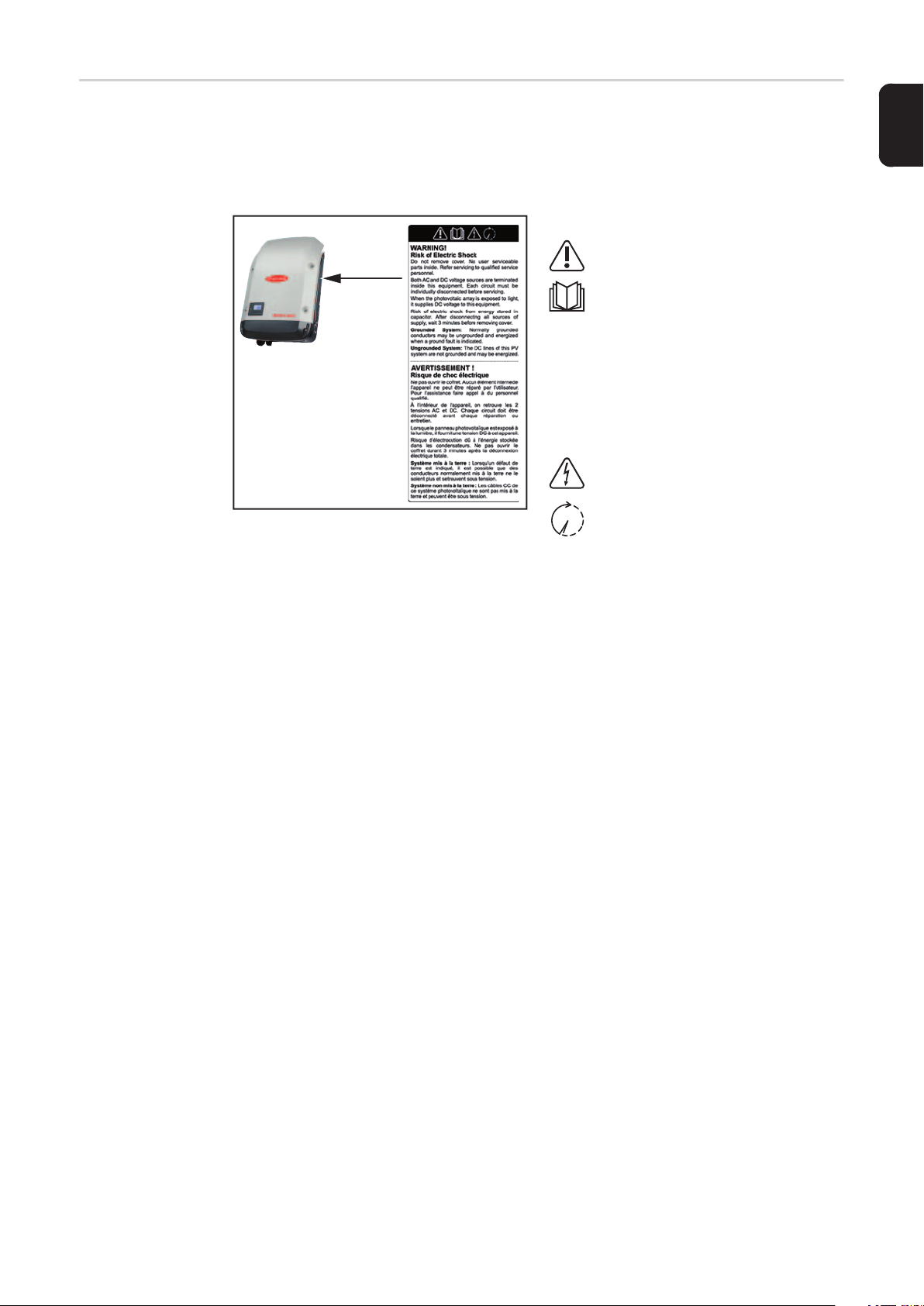
Warning Notices
Affixed to the Device
The inverter contains and displays warning notices and safety symbols. These warning notices and safety symbols must NOT be removed or painted over. The notices and symbols
warn against operating the equipment incorrectly, as this may result in serious injury and
damage.
Safety Symbols:
Danger of serious injury or damage due to incorrect operation
Do not use the functions described until you have thoroughly
read and understood the following
documents:
- these operating instructions
- all operating instructions for
system components of the
photovoltaic system, especially the safety rules
Dangerous electrical voltages
You must wait until the capacitors
have discharged
Text of Warning Notices:
EN-US
WARNING!
Danger of electric shock
Do not remove lid. No parts are to be serviced by the user. Servicing must be carried out
by trained service technicians.
Both AC and DC power sources terminate within the device. Every circuit must be switched
off individually before carrying out maintenance work.
If the solar module field light is exposed it supplies the device with DC voltage.
Danger of electric shock from energy stored in the capacitors. Do not remove the lid until
three minutes have passed since all supply sources were switched off.
Grounded system: Normally grounded cables can be ungrounded and live due to a
ground fault.
Ungrounded system: The DC cables in this photovoltaic system are not grounded and
may be live.
11
Page 14
Data Communication and Solar Net
Fronius Solar Net
and Data Interface
Fronius developed Solar Net to make these system add-ons flexible and capable of being
used in a wide variety of different applications. Fronius Solar Net is a data network that
enables several inverters to be linked to the system add-ons.
Fronius Solar Net is a bus system with ring topology. Just one suitable cable is enough
to provide communication between one or more inverter connected to Fronius Solar Net
and a system add-on.
Different system add-ons are automatically recognized by Fronius Solar Net.
In order to distinguish between several identical system add-ons, each one must be as-
signed a unique number.
In order to clearly define each inverter in Fronius Solar Net, each inverter must also be
assigned an individual number.
You can assign individual numbers as per the "SETUP Menu" section in this manual.
More detailed information on individual system upgrades can be found in the relevant operating instructions or on the internet at http://www.fronius.com
More detailed information on cabling DATCOM components can be found at
http://www.fronius.com/QR-link/4204101938
Installing Option
Cards in Inverters
Information on installing option cards in the inverters and for connecting data communication cables can be found in the installation instructions.
12
Page 15
System monitoring
General If no device special version is present, the inverter is equipped with Wi-Fi enabled system
monitoring Fronius Data Manager 2.0.
The monitoring system includes inter alia the following functions:
- own website with display of actual data and a wide variety of settings
- direct connection-possibility to Fronius Solar.web
- automatic sending of service messages via SMS or e-mail in case of errors
- Internet connection via WiFi or LAN
- Possibility to control the inverter by setting of power limits, minimum or maximum operational times or target operational times
- Controlling the inverter via Modbus (tcp / rtu)
- Allocation of control priorities
- Controlling the inverter by connected meters (Fronius Smart Meter or S0 meter)
- Controlling the inverter via a ripple control signal receiver (eg reactive power setting
or power setting)
- dynamic power reduction considering the own consumption
Further information about the Fronius Data Manager 2.0 can be found online in the Fronius
Data Manager 2.0 operating instructions.
EN-US
Starting for the
First Time via the
Fronius Solar.web App
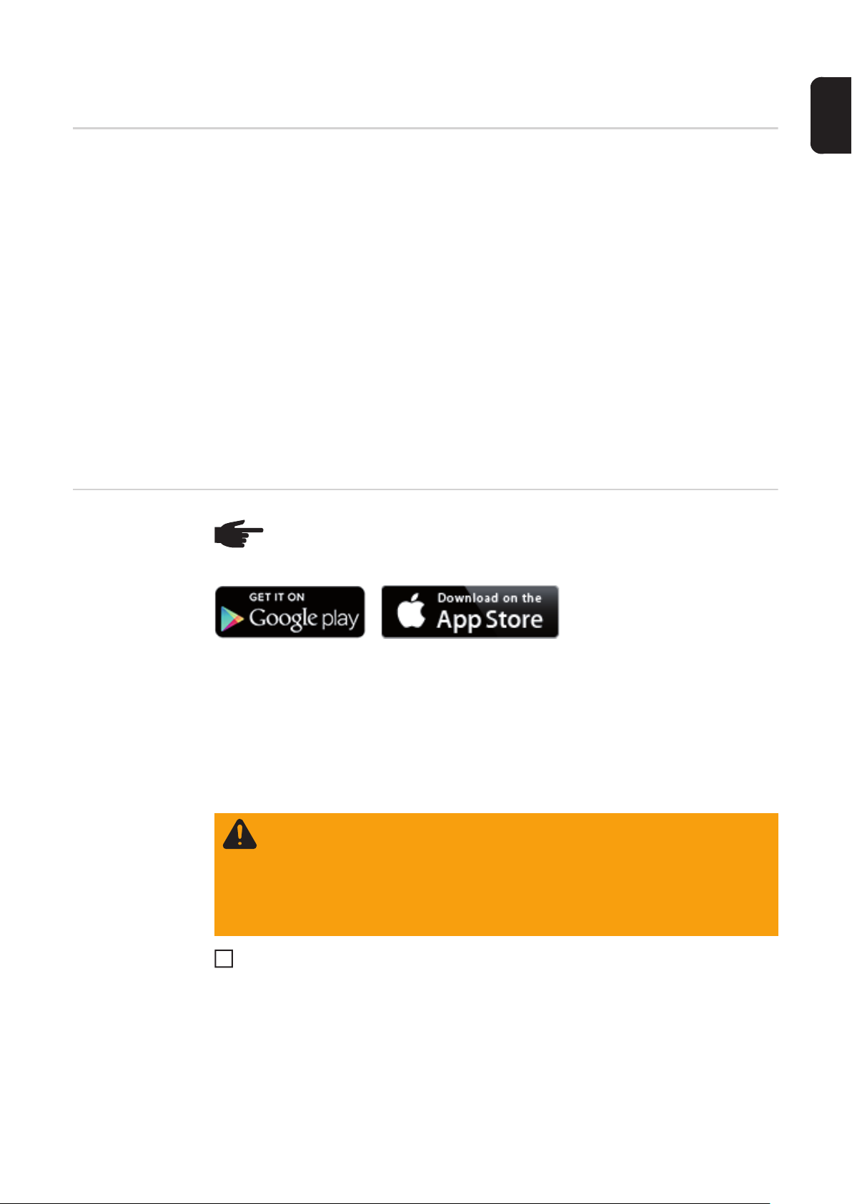
NOTE! The Fronius Solar.web App makes starting Fronius Datamanager 2.0 for
the first time significantly easier.
The Fronius Solar.web App is available in the relevant app store.
To start Fronius Datamanager 2.0 for the first time,
- the Fronius Datamanager 2.0 plug-in card must be installed in the inverter,
or
- there must be a Fronius Datamanager Box 2.0 in the Fronius Solar Net ring.
IMPORTANT! To establish a connection to Fronius Datamanager 2.0, the end device in
question (e.g., laptop, tablet) must be configured as follows:
- "Obtain an IP address automatically (DHCP)" must be activated
WARNING! An electric shock can be fatal. Danger from grid voltage and DC voltage from solar modules.
Before opening the inverter:
- You must wait until the capacitors have discharged.
- Follow the operating instructions when opening the inverter.
- Observe the safety rules and safety instructions contained in the inverter's
operating instructions.
Connect the inverters with Fronius Datamanager 2.0 or Fronius Datamanager Box 2.0
1
in Fronius Solar Net
IMPORTANT! Inverters Fronius IG, Fronius IG Plus, Fronius IG Plus V, Fronius IG
Plus A, Fronius CL, Fronius CL USA, and Fronius IG 300–500 must always be located
at the beginning or end of the Fronius Solar Net ring.
13
Page 16
For Fronius Galvo/Fronius Symo/Fronius Primo only and when linking multiple invert-
2
ers in Fronius Solar Net:
Set the Fronius Solar Net master/slave switch on the Fronius Datamanager 2.0 plugin card as required
- One inverter with Fronius Datamanager 2.0 = master
- All other inverters with Fronius Datamanager 2.0 = slave (the LEDs on the Fro-
nius Datamanager 2.0 plug-in cards are off)
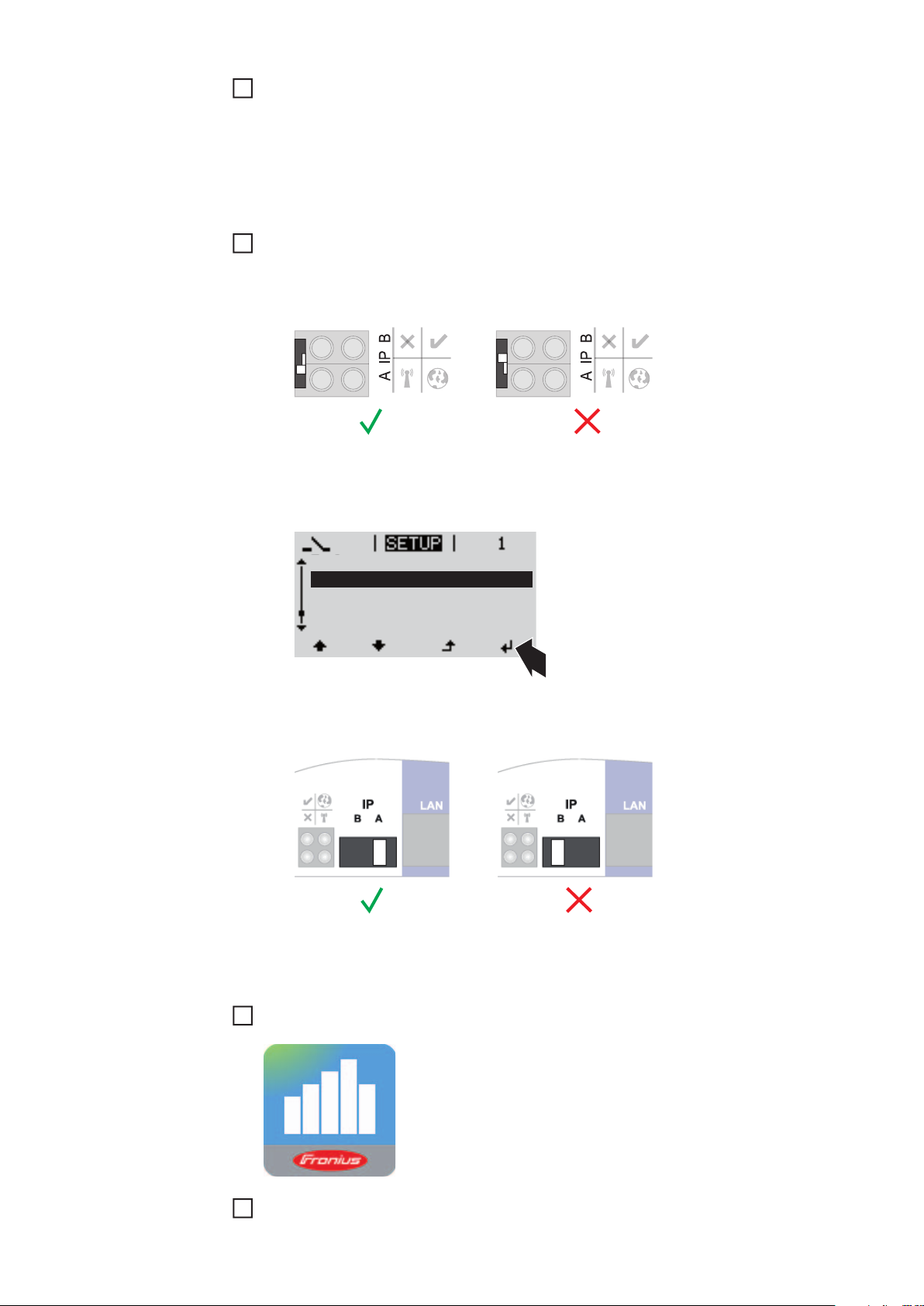
Switch the device to service mode
3
Inverter with Fronius Datamanager 2.0 plug-in card:
- Switch the IP switch on the Fronius Datamanager 2.0 plug-in card to position A
or
- Activate the WIFI Access Point via the Setup menu of the inverter
(the performance of this function depends on the inverter software)
Stand by
WiFi Access Point
DATCOM
USB
Clock
Fronius Datamanager Box 2.0:
- Switch the IP switch on the Fronius Datamanager Box 2.0 to position A
The inverter/Fronius Datamanager Box 2.0 establishes the WLAN Access Point. The
WLAN Access Point stays open for one hour.
Download Fronius Solar.web App
4
14
Run Fronius Solar.web App
5
Page 17
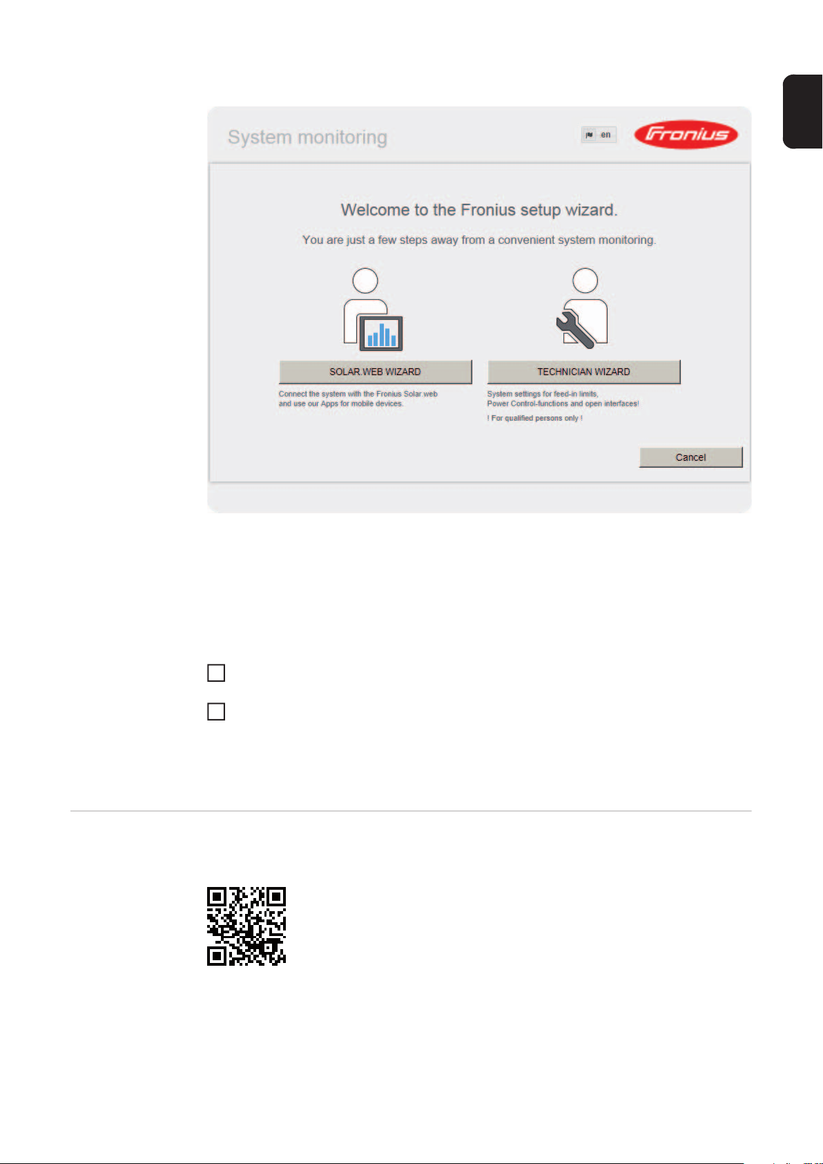
The start page of the Commissioning Wizard appears.
EN-US
More Detailed Information on Fronius
Datamanager 2.0
The Technician Wizard is designed for the installer and includes standard-specific settings.
Running the Technician Wizard is optional.
If the Technician Wizard is run, it is essential to note down the assigned service password.
This service password is required to configure the UC Editor and Counter menu items.
If the Technician Wizard is not run, no specifications for power reduction are set.
The Solar Web Wizard must be run.
If necessary, run the Technician Wizard and follow the instructions
6
Run the Solar Web Wizard and follow the instructions
7
The Fronius Solar.web start page appears.
or
The Fronius Datamanager 2.0 website opens.
More detailed information on Fronius Datamanager 2.0 and other start-up options can be
found at:
http://www.fronius.com/QR-link/4204260191EA
15
Page 18
Keys and symbols
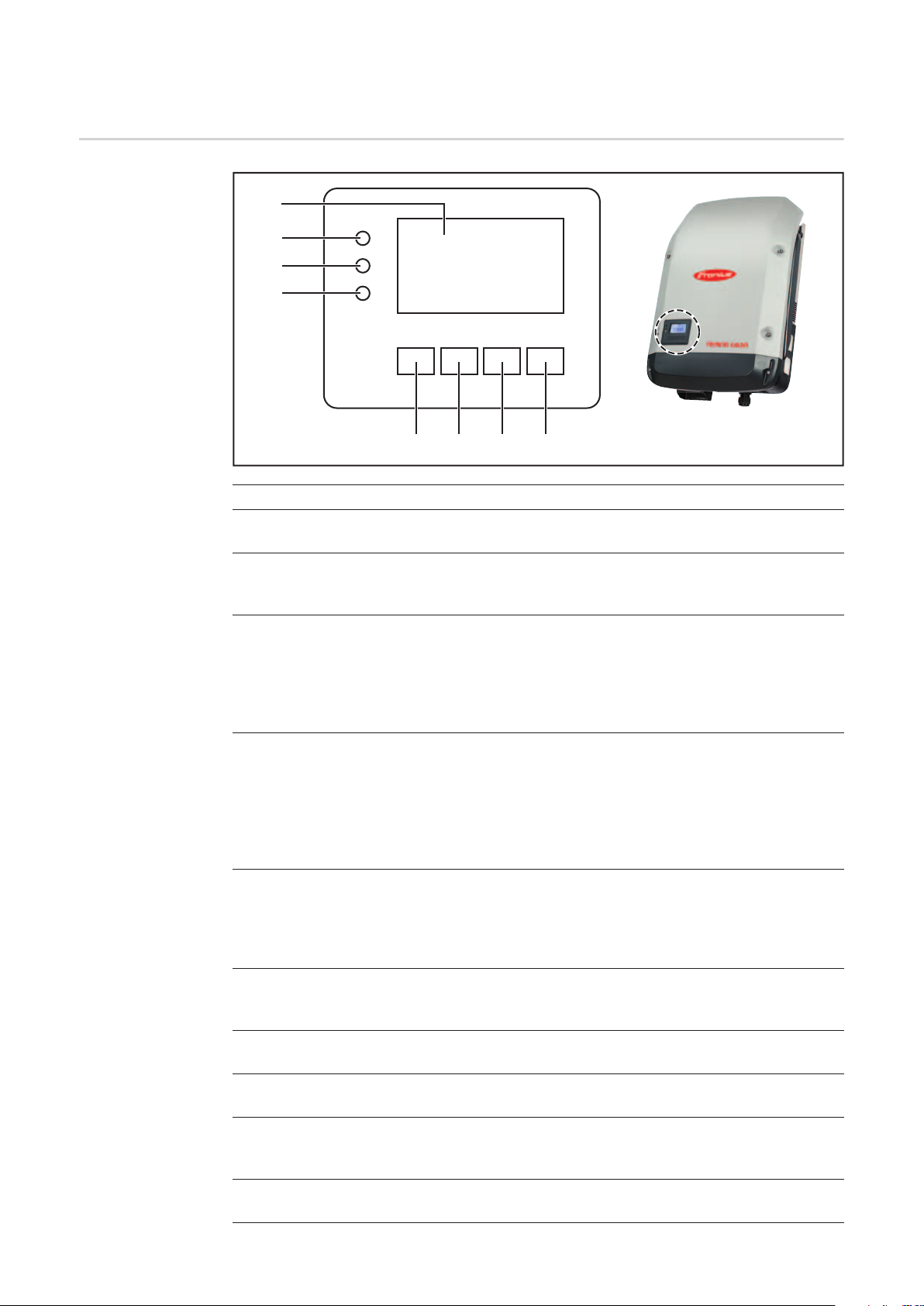
Keys and Symbols
(1)
(2)
(3)
(4)
Item Description
(1) Display
for displaying values, settings, and menus
(5) (6) (7) (8)
Control and Status LEDs
(2) General Status LED (red)
indicates
- when a status code is shown on the display
- interruption of grid power feed operation
- during troubleshooting (the inverter is waiting to be reset or for an error to
be corrected).
(3) Startup LED (orange)
indicates
- if the inverter will enter the automatic startup or self test phase (as soon as
the solar modules yield sufficient power output after sunrise)
- if the inverter has been set to standby operation in the Setup menu (= manual shutoff of operation)
- when the inverter software is being updated.
(4) Operating Status LED (green)
indicates
- if the photovoltaic system is working fault-free following the automatic startup phase of the inverter
- when the grid power feed operation is taking place.
Function keys – each has a different function depending on the selection:
16
(5) "Left/Up" key
for navigating left and up
(6) "Down/Right" key
for navigating down and right
(7) "Menu/Esc" key
for switching to the menu level
to exit the Setup menu
(8) "Enter" key
for confirming a selection
Page 19
The keys are capacitive keys; if they become wet their function may be compromised.
Wipe the keys dry with a cloth if necessary to ensure optimal function.
Display Power for the display comes from the AC grid voltage. The display can be available all day
long depending on the setting in the Setup menu.
IMPORTANT! The inverter display is not a calibrated measuring instrument. Slight deviation from the utility company meter is intrinsic to the system. A calibrated meter is required
to make calculations for the utility company.
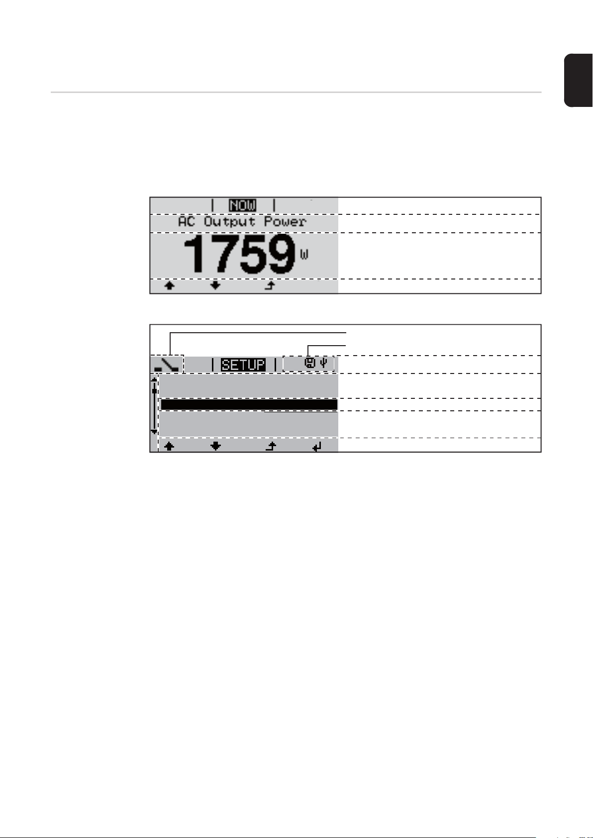
Menu item
Parameter declaration
Display of values, units and status codes
Function key functions
Display area, display mode
Energy-Manager (**)
Inv. no. | Save symbol | USB conn.(***)
EN-US
1
Standby
WiFi Access Point
DATCOM
USB
Relay
(*)
Display area, setup mode
(*) Scroll bars
(**) The Energy Manager symbol
is displayed if the Energy Manager function has been activated
(***) Inv. no. = Inverter DATCOM number,
Store icon – appears briefly when set values are stored,
USB connection – appears if a USB stick has been inserted
Menu item
Previous menu items
Currently selected menu item
Next menu items
Function key functions
17
Page 20
Menu level
Activating Display Illumination
Automatic Deactivation of Display
Illumination /
Switching to the
"NOW" Display
Mode
Accessing the
Menu Level
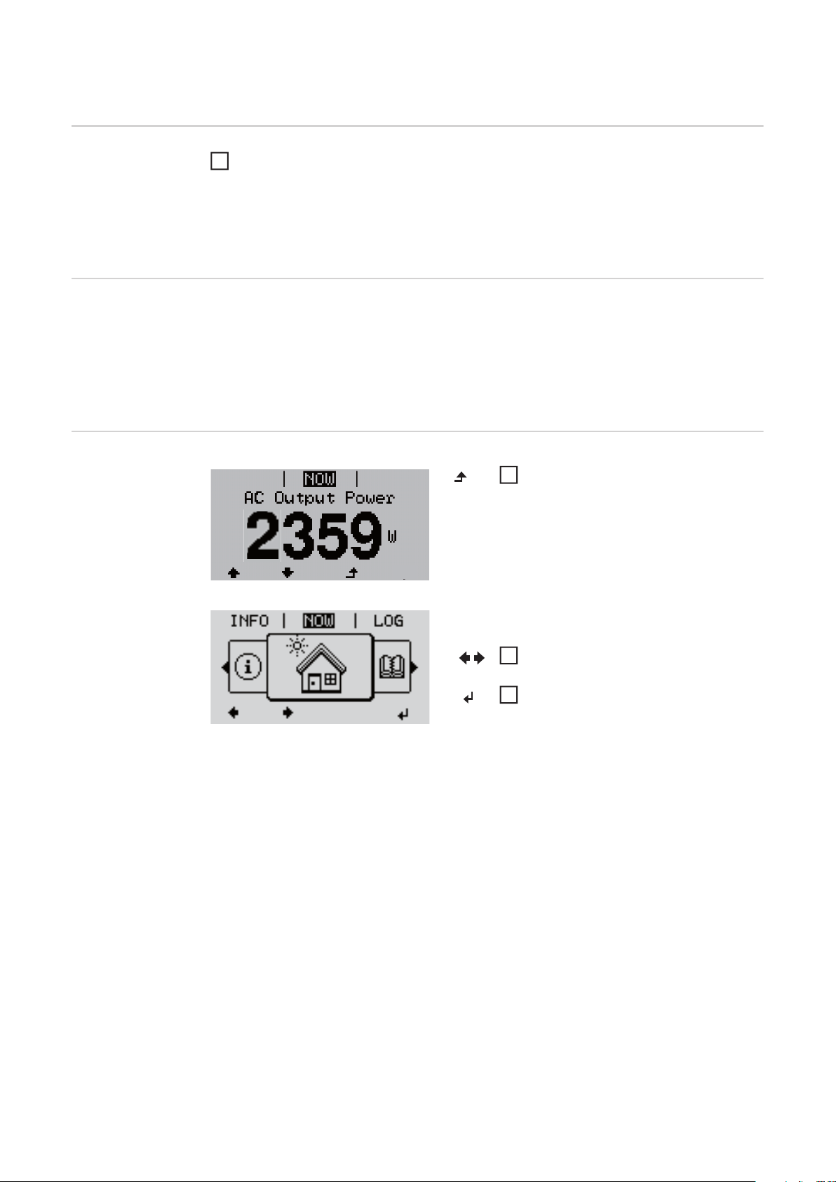
Press any key.
1
The display illumination is activated.
The SETUP menu item offers the choice between a permanently lit or permanently
dark display under "Display Settings."
If no key is pressed for 2 minutes:
- the display illumination turns off automatically and the inverter switches to the "NOW"
display mode (if the display illumination is set to automatic)
- the inverter can be switched to the "NOW" display mode from any menu level, except
for the "Standby" menu item
- the current output power is displayed.
Press the "Menu" key
1
The display switches to the menu level
Select the desired menu item using
2
the "Left" or "Right" key
Access the desired menu item by
3
pressing the "Enter" key
18
Page 21

Menu items NOW, LOG, and GRAPH
EN-US
NOW
LOG
GRAPH
GRAPH
GRAPH
NOW
(displays real-time values)
LOG
(data logged on the current day, from the
current calendar year, and since using the
inverter for the first time)
GRAPH
graphically represents the course of the
output power during the day. The time
axis is automatically scaled
Press the "Back" key to close the display
Values Displayed
in the Menu Items
NOW and LOG
Data displayed in menu item NOW:
AC Output Power (W)
AC Reactive Power (VAr)
AC Voltage (V)
AC Output Current (A)
AC Frequency (Hz)
PV Array Voltage (V)
PV Array Current (A)
Time / Date
Time and date on the inverter or Fronius Solar Net ring
19
Page 22

Data displayed in menu item LOG:
(for the current day, the current calendar year, and since using the inverter for the first
time)
AC Energy Yield (kWh / MWh)
energy fed into the grid during the monitored period
Due to the variety of different monitoring systems, there can be deviations between the
readings of other metering instruments and the readings from the inverter. For determining the energy supplied to the grid, only the readings of the calibrated meter supplied by
the electric utility company are relevant.
AC Maximum output power (W)
highest power feeding in during the monitored period
Earnings
amount of money earned during the monitored period (currency can be selected in the
Setup menu)
As was the case for the output energy, readings may differ from those of other instruments.
"The Setup Menu" section describes how to set the currency and rate for the energy supplied.
The factory setting depends on the respective country-specific setup.
CO2 savings (g / kg)
CO2 emissions saved during the period in question
The value for CO2 savings depends on the power station facilities and corresponds to the
CO2 emissions that would be released when generating the same amount of energy. The
factory setting is 0.53 kg / kWh (source: DGS – Deutsche Gesellschaft für Sonnenenergie
e.V. (German Society for Solar Energy).
AC Max. Voltage L-N (V)
highest reading of voltage between the conductor and neutral conductor during monitored
period
PV Array Max. Voltage (V)
highest reading of solar module voltage during monitored period
Operating Hours
indicates how long the inverter has been operating (HH:MM)
IMPORTANT! The time must be set correctly for day and year values to be displayed
properly.
20
Page 23

The SETUP menu item
Presetting Following commissioning, the inverter is preconfigured according to the country setup.
The SETUP menu item enables you to easily customize the inverter’s preset parameters
to your needs.
EN-US
SETUP
Navigation in the
SETUP Menu Item
GRAPH
NOTE! Because of software updates, certain functions may be available for your
device but not described in these operating instructions or vice versa. In addition,
individual figures may also differ slightly from the operating elements of your device. However, the function of these operating elements is identical.
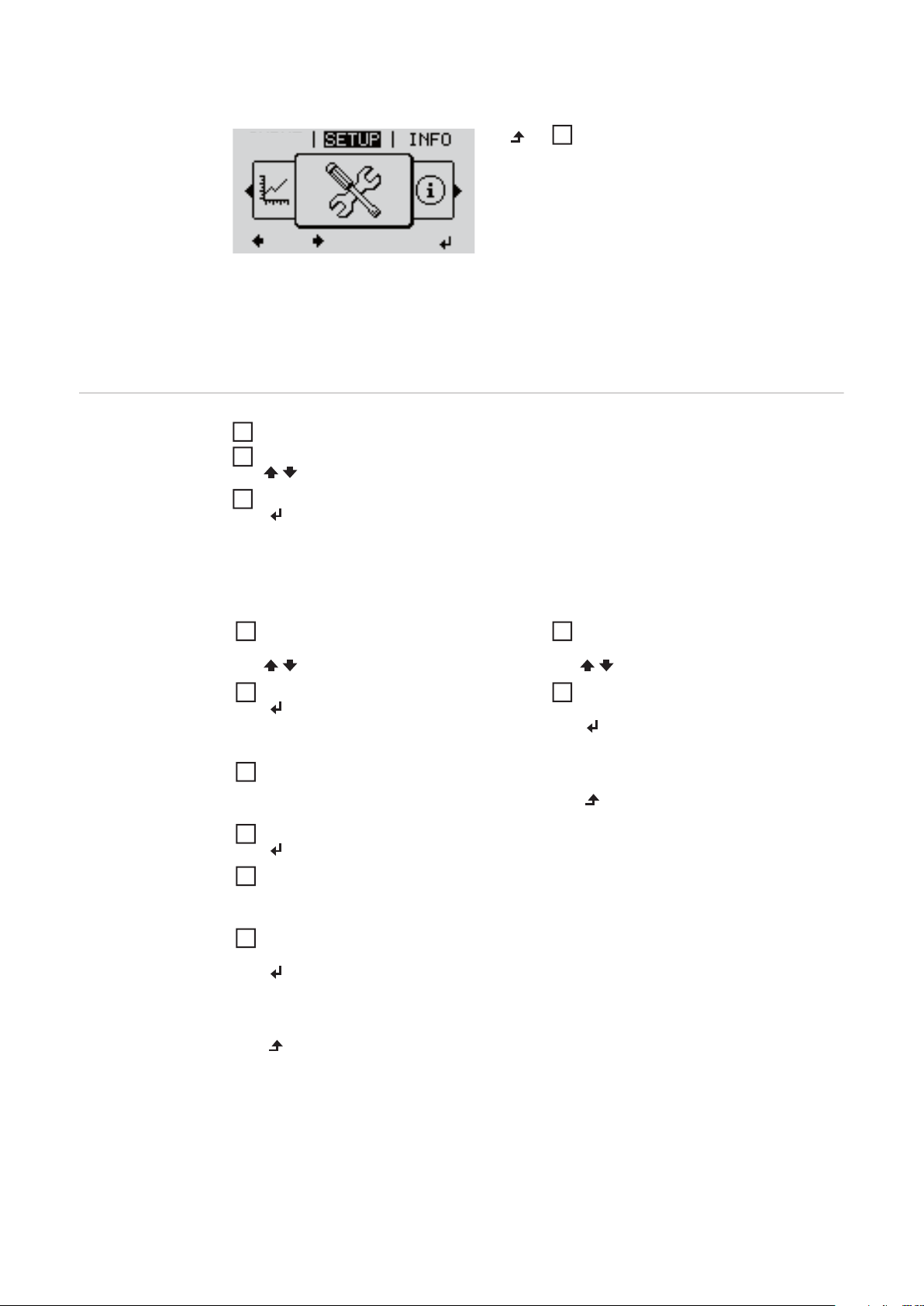
Accessing the SETUP menu item
GRAPH
SETUP
(Setup menu)
Select the "Setup" menu item at
1
menu level using the "Left" or "Right"
key
Press the "Enter" key
2
"SETUP" menu level selected
Standby
WiFi Access Point
DATCOM
USB
Relay
"Standby" item
Scrolling through the items
Example: "WiFi Access Point" menu item
The first SETUP menu item is displayed:
"Standby"
Scroll through the available menu
3
items using the "Up" and "Down" keys
21
Page 24
Exiting a menu item
To exit a menu item, press the "Back"
GRAPH
4
key
The menu level is displayed
If no key is pressed for 2 minutes
- the inverter switches to the "NOW" menu item from anywhere within the menu level
(exception: Setup menu item "Standby")
- the display illumination turns off
- the current power of feeding in is displayed.
General Setup
Menu Item Settings
Accessing the SETUP menu item
1
Use the "Up" and "Down" keys to select the desired menu item
2
Press the "Enter" key
3
The first digit of a value to be set flash-
The available settings are displayed:
es:
Use the "Up" and "Down" keys to se-
4
lect a value for the first digit
Press the "Enter" key
5
Use the "Up" and "Down" keys to se-
4
lect the desired setting.
Press the "Enter" key to save and ap-
5
ply the selection.
The second digit of the value flashes.
Repeat steps 4 and 5 until...
6
Press the "Esc" key to discard the selection.
the entire value flashes.
Press the "Enter" key
7
Repeat steps 4–6 for units or other
8
values to be set until the unit or value
to be set flashes.
Press the "Enter" key to save and ap-
9
ply the changes.
22
Press the "Esc" key to discard the
changes.
The currently selected item is displayed. The currently selected item is displayed.
Page 25
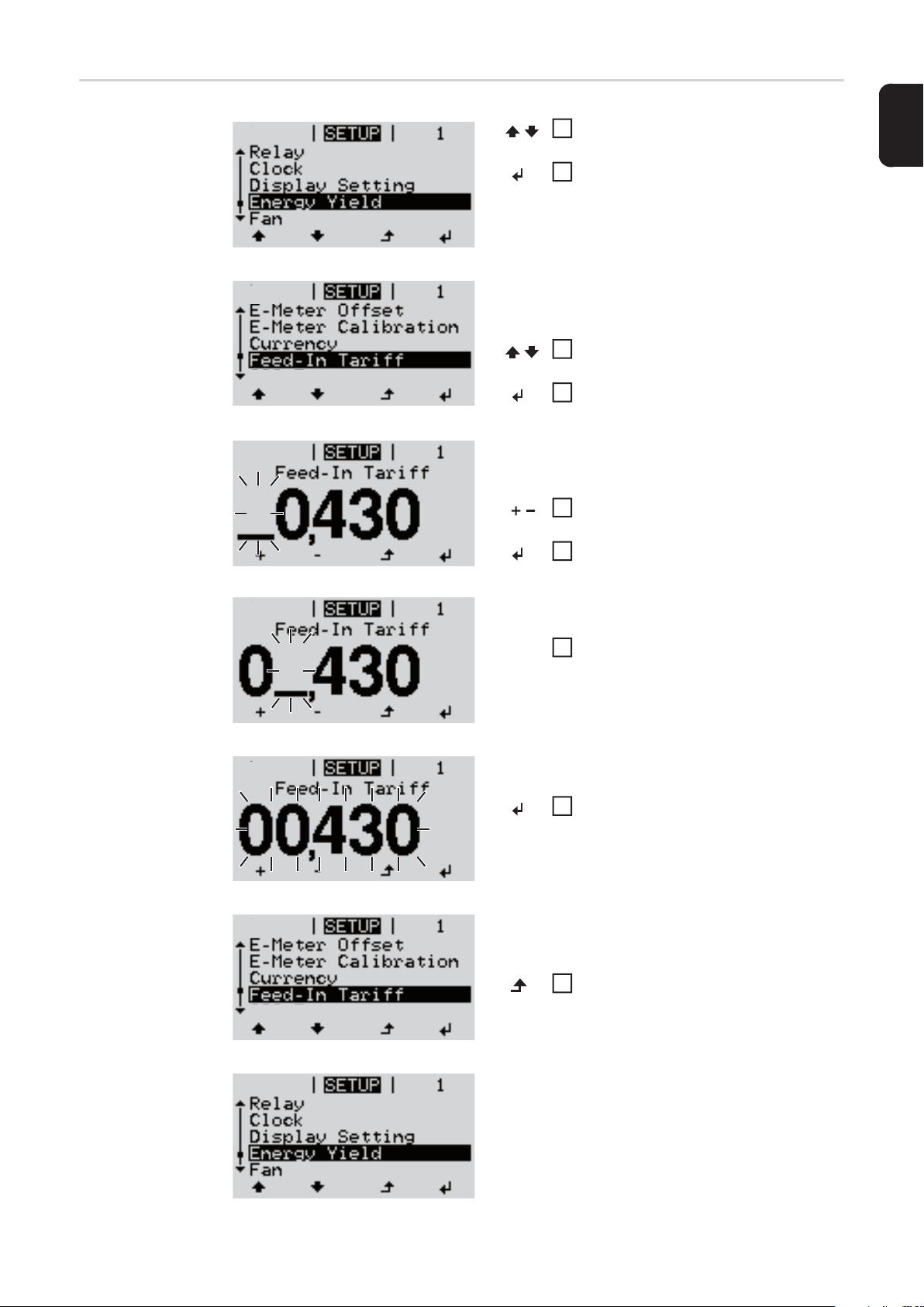
Application Example: Setting
the Feed-In Tariff
Select the Setup menu item "Energy
1
yield"
Press the "Enter" key
2
The overview of values that can be selected is displayed.
Use the "Up" or "Down" keys to select
3
"Energy yield"
Press the "Enter" key
4
The feed-in tariff is displayed.
The tens digit flashes.
Use the "Up" and "Down" keys to se-
5
lect a value for the tens digit.
Press the "Enter" key
6
EN-US
The units digit flashes.
Repeat steps 5 and 6 for the units dig-
7
it and for the three digits after the decimal point until ...
the set feed-in tariff flashes.
Press the "Enter" key
8
The feed-in tariff is applied; the overview
of the values that can be set is displayed.
Press the "Esc" key
9
The Setup menu item "Energy yield" is
shown.
23
Page 26

The Setup menu item
Standby Manual activation/deactivation of the standby mode
- No power is fed into the grid.
- The Startup LED lights up orange.
- In standby mode, no other menu item can be accessed or set in the menu level.
- The automatic switching to the "NOW" menu item after 2 minutes if no key is pressed
is not activated.
- The Standby mode can only be deactivated manually by pressing the "Enter" key.
- Grid supply operation can be resumed at any time (deactivate "Standby").
Setting standby mode (manual shutoff for feeding energy into the grid):
Select the "Standby" item
1
Press the "Enter" key
2
The display alternates between "STANDBY" and "ENTER."
The Standby mode is now activated.
The Startup LED lights up orange.
Restoring the grid feed:
WiFi Access
Point
In Standby mode, the display alternates between "STANDBY" and "ENTER."
Press "Enter" to restore the grid power feed operation
1
The "Standby" item is displayed.
The inverter also switches to the Startup phase.
After the grid power feed operation is restored, the Operation Status LED lights up green.
For activating / deactivating of the WiFi Access Point (e.g. to set a system monitoring)
Adjustment range WiFi Access Point
[stopped]
Activate WiFi ?
To activate the WiFi Access Point press the Enter key.
WiFi Access Point
[active]
24
The SS-ID (SS) and the password (PW) are displayed.
Deactivate WiFi AP ?
To deactivate the WiFi Access Point press the Enter
key.
Page 27

***
WiFi Access Point
[not available]
Is displayed, when no system monitoring is present at the inverter.
DATCOM Check of a data communication, entry of the inverter number, DATCOM night mode, pro-
tocol settings
Setting range Status / Inverter number / Protocol type
Status
Displays data communication available via Solar Net or an error that occurred in data communication
Inverter Number
Number setting (address) of the inverter in a setup where multiple solar inverters are linked
together
Setting range 00 – 99 (00 = 100 inverter)
Factory setting 01
EN-US
IMPORTANT! Each inverter must be assigned its own address when using multiple invert-
ers in a data communications system.
Protocol type
Defines the communication protocol used to transmit data:
Setting range Solar Net / Interface Protocol *
Factory setting Solar Net
* The protocol type Interface Protocol only works without the Datamanager card. Available
Datamanager cards must be removed from the inverter.
USB Value settings when using a USB stick
Setting range Safely remove hardware / software update / logging interval
Safely remove hardware
To remove a USB stick from the USB A socket on the data communication rack without
losing data.
The USB stick can be removed:
- when OK is displayed
- when the "Data Transfer" LED is no longer flashing or illuminated
Software update
For updating inverter software using a USB stick.
IMPORTANT! Firmware may only be updated by Fronius Service Technicians or Fronius
Service Partners.
25
Page 28

Procedure:
Download the "froxxxxx.upd" update file
1
(e.g., at http://www.fronius-usa.com; xxxxx stands for the respective version number)
NOTE! To ensure problem-free updates of inverter software, the USB stick
should have no hidden partitions and no encryption (see section "Suitable USB
Sticks).
Save the update file to the highest data level of the USB stick
2
Open the data communication area
3
Insert the USB stick with the update file into the USB socket in the data communication
4
area
In the Setup menu, select the menu item "USB" and then "Update Software"
5
Press the "Enter" key
6
Wait until a comparison of the current software version on the inverter and the new
7
software version is displayed:
- Page 1: Recerbo software (LCD), key controller software (KEY), country-setup
version (SET)
- Page 2: Power stage set software
Press the "Enter" key after every page
8
The inverter begins copying the data.
"UPDATE" and the saving progress of the individual tests is displayed in % until the data
for all electronic assemblies is copied.
After the copying is complete the inverter updates the required electronic assemblies one
after the other.
"UPDATE", the relevant assembly, and the update progress are displayed in %.
The inverter updates the display in the last step.
The display remains dark for approx. 1 minute, the control and status LEDs flash.
When the software update is complete, the inverter switches to the startup phase and then
to grid power feed operation. The USB stick can be removed.
Individual settings in the Setup menu are retained when the inverter software is updated.
Logging Interval
Activating / deactivating the logging function, as well as setting the logging interval
Unit Minutes
Setting range 30 Min. / 20 Min. / 15 Min. / 10 Min. / 5 Min. / No Log
Factory setting 30 Min.
30 Min. The logging interval is 30 minutes; new logging data are saved
to the USB stick every 30 minutes.
20 Min.
15 Min.
10 Min.
5 Min. The logging interval is 5 minutes; new logging data are saved to
the USB stick every 5 minutes.
26
No Log No data are saved
Page 29

IMPORTANT! The time must be set correctly in order for the logging function to work properly.
Relay Activate Relay, Relay Settings, Relay Test
Setting range Relay Mode / Relay Test / Switch on Point* / Switch off Point*
* only shown if the 'E-manager' function has been activated under "Relay Mode."
Relay Mode
For selection of the various functions of the potential-free switching contact in the data
communications area:
- Alarm function
- Active output
- Energy manager
Setting range ALL / Permanent / OFF / ON / E-manager
Factory setting ALL
Alarm function:
Permanent /
ALL:
Active output:
ON: The potential-free switching contact NO is switched on at all times
OFF: The potential-free switching contact NO is switched off
Energy manager:
E-manager: You can find additional information on the "Energy manager" function
Switches the potential-free switching contacts for continual and temporary service codes (e.g., brief interruption of grid power feed operation, a service code occurs a set number of times per day – can be set
in the "BASIC" menu)
while the inverter is operating (as long as the display lights up or appears)
in the "Energy Manager" section below
EN-US
Relay test
Functional test to check if the potential-free switching contact works
Switch on point (only if "Energy manager" function is activated )
for setting the effective power limit from which the potential-free switching contact will be
switched on
Factory setting 1000 W
Setting range Switch off point – max. power rating of the inverter / W / kW
Switch off point (only if the "Energy manager" function is activated)
for setting the effective power limit from which the potential-free switching contact will be
switched off
Factory setting 500
Setting range 0 – switch on point / W / kW
27
Page 30

Time/Date Setting the time, date and automatic adjustment for daylight saving time
Setting range Set time / Set date / Time display format / Date display format /
Daylight saving time
Set time
Setting the time (hh:mm:ss or hh:mm am/pm, depending on the setting under Time display
format)
Set date
Setting the date (dd.mm.yyyy or mm/dd/yyyy, depending on the setting under Date display
format)
Time display format
For specifying the format in which the time is displayed
Setting range 12 hrs / 24 hrs
Factory setting depends on the country setup
Date display format
For specifying the format in which the date is displayed
Setting range mm/dd/yyyy / dd.mm.yy
Factory setting depends on the country setup
Display Settings
Daylight saving time
Activating/deactivating the automatic adjustment for daylight saving time
NOTE! Only use the function for automatic daylight savings adjustment when
there are no LAN or WLAN-compatible system components in a Fronius Solar Net
Ring (e.g., Fronius Datalogger Web, Fronius Datamanager or Fronius Hybridmanager).
If there are LAN or WLAN-compatible system components, set this function on
the web interface for the system component.
Setting range on/off
Factory setting on
IMPORTANT! The time and date must be set correctly for day and year values to be displayed properly.
Setting range Language / Night mode / Contrast / Illumination
Language
Setting the display language
28
Setting range German, English, French, Dutch, Italian, Spanish, Czech, Slo-
vak, etc.
Page 31

Night Mode
DATCOM night mode; controls DATCOM and display operation at night or when there is
insufficient DC voltage available
Setting range AUTO / ON / OFF
Factory setting OFF
AUTO: DATCOM operation is constant as long as a Datalogger is connected to an
active, uninterrupted Solar Net.
The display is dark during the night and can be activated by pressing any
key.
ON: DATCOM operation is constant. The inverter provides 12 V constantly to
supply Solar Net with power. The display is always active.
IMPORTANT! The power consumption of the inverter is increased at night
to approximately 7 W when the DATCOM night mode is ON or on AUTO and
Solar Net components are connected.
OFF: No DATCOM operation at night, the inverter requires no AC power to supply
Solar Net.
The display is deactivated at night; the Fronius Datamanager is not available.
EN-US
Contrast
set contrast on the display
Setting range 0–10
Factory setting 5
Since contrast depends on temperature, it may be necessary to adjust the "Contrast" menu
item when environmental conditions change.
Illumination
Initial setting for display illumination
The "Illumination" menu item only applies to the display background illumination.
Setting range AUTO / ON / OFF
Factory setting AUTO
AUTO: The display illumination is activated by pressing any key. If no key is pressed
for 2 minutes, the display backlight goes out.
ON: The display illumination will be permanently on when the inverter is active.
OFF: The display illumination will be permanently off.
29
Page 32

Energy Yield Setting
- an OFFSET value for the Total energy display
- a measurement correction value for the day, year and total energy display
- the currency
- the feed-in tariff
Setting range E-meter offset/E-meter calibration/Currency/Feed-in tariff
E-meter offset
Specification of a value for the energy supplied that is added to the currently supplied energy (e.g., the transfer value when an inverter is replaced)
Unit Wh/kWh/MWh
Setting range 5-digit
Factory setting 0
E-meter calibration
Specification of a correction value so that the data shown on the inverter display correspond to the calibrated data shown on the electric meter
Unit %
Setting range -5.0 to +5.0
Factory setting 0
Currency
Currency setting
Setting range 3-digit, A-Z
Feed-in tariff
Charge rate setting for the energy fed into the grid
Setting range 2-digit, 3 decimal places
Factory setting (depends on the country setup)
Fan for checking the fan functionality
Setting range Test fan 1 / Test fan 2 (depends on device)
- Use the "Up" and "Down" keys to select the desired fan
- Press the "Enter" key to start testing the selected fan
- The fan runs until the menu is exited by pressing the "Esc" key
30
Page 33

Arc Detection for checking arc detection/interruption
Setting range ArcDetector Status/Start Self-test
Arc.det. Status
displays the current status of arc detection/interruption
Start Self-test
self-test to check whether the inverter interrupts grid power feed operation when an arc
is detected.
Test procedure:
Select "Arc Detection" in the Setup menu
1
Press the "Enter" key
2
Use the up and down keys to select "Start Self-test"
3
Press the "Enter" key
4
The self-test starts. The arc detection/interruption function simulates an arc and sends
the corresponding signal to the inverter.
If the test is successful, the inverter disconnects from the grid and stops grid power feed
operation.
EN-US
The message "Self-test completed and Start AFCI" is shown on the display.
Confirm the indication by pressing the "Enter" key
5
31
Page 34

The INFO menu item
INFO
Measured values
LT status
Grid status
INFO
(information on device and software)
Measured values Display range: PV Ins. / Fan #1 / U PV1
PV Ins.
Insulation resistance of the PV system
(for ungrounded solar modules and for solar modules grounded at the
negative pole)
Fan #1
Percentage value of the fan's target power
U PV1
Current DC voltage at the terminal, also if the inverter is not feeding
in at all (from the first MPP Tracker)
LT status The status display of the last error that occurred in the inverter can be
shown.
IMPORTANT! Status codes 306 (Power low) and 307 (DC low) appear naturally every morning and evening due to low solar irradiance.
These status codes are not the result of a fault.
- After pressing the "Enter" key, the power stage set status and the
last error that occurred are displayed
- Use the "Up" and "Down" keys to scroll through the list
- Press the "Back" key to exit the status and error list
Grid status The last 5 grid errors that occurred can be displayed:
- After pressing the "Enter" key, the last 5 grid errors that occurred
are displayed
- Use the "Up" and "Down" keys to scroll through the list
- Press the "Back" key to exit the grid error display
32
Page 35

Device Information
The device is used to display settings relevant to a power supply company. The displayed
values depend on the respective country setup or device-specific inverter settings.
Display range General / Country Setup / MPP Tracker / AC Monitoring / AC
Voltage Limits / AC Frequency limits / Q-Mode / AC Power Limits / AC Voltage Derating / Fault Ride Through
General: Device type
Fam.
Country Setup: Setup
Country setup
Version
Country setup version
Group
Inverter software update group
MPP Tracker: Tracker 1
AC Monitoring: GMTi
Startup time of the inverter in s
GMTr
Restart time in s after a grid error
EN-US
ULL
Grid voltage average value over 10 minutes in V
LLTrip
Detection time for long-term voltage monitoring
AC Voltage Limits: UILmax
Upper inner grid voltage value in V
UILmin
Lower inner grid voltage value in V
AC Frequency Limits: FILmaw
Upper inner grid frequency value in Hz
FILmin
Lower inner grid frequency value in Hz
Q-Mode: Current power factor cos phi
(e.g., constant cos(phi) / constant Q / Q(U) characteristic / etc.)
AC Power limits: Max. P AC
manual power reduction
33
Page 36

AC Voltage Derating: Status
ON / OFF voltage-dependent power reduction
GVDPRe
Threshold from which the voltage-dependent power reduction
begins
GVDPRv
Reduction gradient used to reduce the power, e.g.: 10% per volt
above the GVDPRe threshold.
Message
Activates the dispatch of an info message via Fronius Solar Net
Fault Ride Through: Status – default setting: OFF
If the function is activated, the inverter does not switch off im-
mediately when a short-term interruption to the AC voltage oc-
curs (outside of the limits set by the grid supplier); instead it
continues to supply power for a defined time.
DB min – default setting: 90%
"Dead Band Minimum" setting (%)
DB max – default setting: 120%
"Dead Band Maximum" setting (%)
k-Fac. default setting: 0
Version Display of version number and serial number of the PC boards installed in the inverter (e.g.,
for service purposes)
Display range Display/Display Software/Integrity Checksum/Memory Card/
Memory Card #1/Power Stage/Power Stage Software/EMI Fil-
ter/Power Stage #3/Power Stage #4
34
Page 37

Switching the key lock on and off
General The inverter comes equipped with a ‘Key lock’ function.
When the ‘Keylock’ function is active, the Setup menu cannot be accessed, e.g., to protect
against setup data being changed by accident.
You must enter code 12321 to activate / deactivate the ‘Key lock’ function.
EN-US
Switching the Key
Lock On and Off
Press the "Menu" key.
1
The menu level is displayed.
Press the unassigned "Menu / Esc"
2
key
5 x.
In the "CODE" menu, the "Access Code"
is displayed; the first digit flashes.
Enter code 12321: Use the "Up" and
3
"Down" keys to select a value for the
first digit of the code.
Press the "Enter" key.
4
The second digit flashes.
Repeat steps 3 and 4 for the second,
5
third, fourth and fifth digit in the code
until...
...the set code flashes.
Press the "Enter" key.
6
In the "LOCK" menu, the "Key lock" function is displayed.
Use the "Up" and "Down" keys to
7
switch the key lock on or off:
ON = the key lock function is activated (the SETUP menu item cannot be
accessed)
OFF = the key lock function is deactivated (the SETUP menu item can be
accessed).
Press the "Enter" key.
8
35
Page 38

USB Stick as a Data Logger and for Updating Inverter Software
USB Stick as a
Data Logger
Suitable USB
Sticks
A USB stick connected to the USB A socket can act as a data logger for an inverter.
Logging data saved to the USB stick can at any time
- be imported into the Fronius Solar.access software via the included FLD file
- be viewed directly in third-party applications (e.g., Microsoft® Excel) via the included
CSV file.
Older versions (up to Excel 2007) have a row limit of 65536.
Further information on "Data on a USB stick", "Data volume and storage capacity" as well
as "Buffer memory" can be found at:
http://www.fronius.com/QR-link/4204260171EN
Due to the number of USB sticks on the market, we cannot guarantee that every USB stick
will be recognized by the inverter.
Fronius recommends using only certified, industrial USB sticks (look for the USB-IF logo).
The inverter supports USB sticks using the following file systems:
- FAT12
- FAT16
- FAT32
Fronius recommends that the USB stick only be used for recording logging data or for updating the inverter software. USB sticks should not contain any other data.
USB symbol on the inverter display, e.g., in the "NOW" display mode:
When the inverter recognizes a USB stick,
the USB symbol will appear at the top right
of the display.
When inserting the USB stick, make sure
that the USB symbol is displayed (it may
also be flashing).
NOW
AC Output Power
36
Page 39

NOTE! Please be aware that in outdoor applications the USB stick may only function in a limited temperature range. Make sure, for example, that the USB stick
will also function at low temperatures for outdoor applications.
EN-US
USB Stick for Updating Inverter
Software
Removing the
USB Stick
The USB stick can be used to help end customers update inverter software via the USB
menu item in the SETUP menu item: the update file is first saved on the USB stick and then
transferred to the inverter. The update file must be saved in the USB stick root directory.
Safety information for removing a USB stick
IMPORTANT! To prevent a loss of data,
X
Do not disconnect
USB-Stick
while LED is flashing!
the connected USB stick should only be
removed under the following conditions:
- via the SETUP and "Safely remove
USB / hardware" menu items
- when the "Data Transfer" LED is no
longer flashing or illuminated.
37
Page 40

The Basic menu
General The following important parameters are set in the Basic menu for the installation and op-
eration of the inverter:
Accessing the
Basic menu
- DC operating mode
- Fixed voltage
- MPPT1 initial voltage
- USB logbook
- Insulation settings
- TOTAL reset
- Event meter
Press the "Menu" key.
1
The menu level is displayed.
Press the unassigned "Menu / Esc"
2
key
5 x.
In the "CODE" menu, the "Access Code"
is displayed; the first digit flashes.
Enter code 22742: Use the "Up" and
3
"Down" keys to select a value for the
first digit of the code.
Press the "Enter" key.
4
Access Code
MPP Tracker 1
USB Eventlog
SMS / Relay
Grounding Settings
Insulation Settings
The second digit flashes.
Repeat steps 3 and 4 for the second,
5
third, fourth and fifth digit in the code
until...
...the set code flashes.
Press the "Enter" key.
6
The Basic menu is shown.
Use the "Up" and "Down" keys to se-
7
lect the desired item.
Edit the selected item by pressing the
8
"Enter" key.
Press "Esc" to exit the Basic menu.
9
38
Page 41

Items in the Basic
Menu
The Basic menu contains the following items:
EN-US
MPP Tracker 1
- DC operating mode:
MPP AUTO
FIX
MPP USER
- Fixed voltage:
For entering the fixed voltage, 120–440 V
- MPPT1 initial voltage:
For entering the MPPT1 initial voltage, 120–440 V
USB logbook
Activating or deactivating the function to save all error messages to a USB stick
AUTO / OFF / ON
SMS / Relay
- Event delay:
For entering the delay time from when an SMS is sent or from when the relay should
switch
900–86400 seconds
- Event meter:
For entering the number of errors following which an SMS is sent or the relay should
switch:
10–255
Ground Settings
- Ground mode:
Off / Positive / Negative
- Ground monitoring
(only displayed if the ground mode is set to Positive or Negative):
Warn Err / Error / Warning
Insulation settings
(only displayed if the ground mode is set to Negative or Off)
- Insulation warning:
to activate and deactivate the insulation monitoring with display of a warning without
interrupting feed-in in the event of an insulation error
ON / OFF (depends on the country setup)
- Threshold warning:
to set an insulation threshold below which the inverter displays a warning (without
interrupting feed-in)
0–1000 kOhm (depends on the country setup set)
- Threshold error:
to set an insulation threshold under which the inverter displays an error message
and interrupts feed-in
0–1000 kOhm (depends on the country setup)
39
Page 42

TOTAL Reset
resets the max. and min. voltage values and the max. power of feeding in in the LOG
menu item to zero.
Once you have reset the values, this cannot be undone.
To reset the values to zero, press the "Enter" key.
"CONFIRM" is displayed.
Press the "Enter" key again.
The values are reset and the menu is displayed.
40
Page 43

Status Diagnosis and Troubleshooting
EN-US
Displaying Status Codes
Total Failure of
the Display
Class 1 Status
Codes
Your inverter is equipped with a self diagnostic system that automatically identifies a large
number of possible operation issues by itself and displays them on the screen. This enables you to know immediately if there are any malfunctions in the inverter, the photovoltaic
system or any installation or operating errors.
Whenever the self diagnostic system has identified a particular issue, the respective status
code is shown on the screen.
IMPORTANT! Status codes may sometimes appear briefly as a result of the control response from the inverter. If it subsequently continues to operate normally, there has not
been a system error.
If the display remains dark for a long time after sunrise:
- check the AC voltage at the inverter's connections:
the AC voltage must be 208–240 V (+10% / -12%) according to the grid.
Status codes in class 1 are typically temporary. Their cause lies in the grid.
Your inverter's first reaction is to disconnect from the grid. Thereafter, the grid will be
checked for the duration of the observation period stipulated. If, after the end of this period,
no further defect is identified, your inverter resumes grid power feed operation.
Code Description Details Rectification
102 AC voltage too high
103 AC voltage too low
105 AC frequency too high
106 AC frequency too low
107 AC grid outside of tolerances
108 Stand alone operation detect-
ed
Class 2 Status
Codes
Code Description Details Rectification
212 Overvoltage at L1-N Grid conditions are being test213 Undervoltage at L1-N
222 Overvoltage at L2-N
223 Undervoltage at L2-N
240 Arc detected
Grid conditions are being tested and as soon as they are
back within the permissible
range, the inverter will resume
grid power feed operation.
ed and as soon as they are
back within the permissible
range, the inverter will resume
grid power feed operation.
The status code is displayed
for approx. 4 seconds.
Check grid connections.
If this status code keeps recurring, contact your system installer.
Check grid connections. If this
status code keeps recurring,
contact your system installer.
-
41
Page 44

Code Description Details Rectification
If an arc has been detected,
241 Arc detected
242 Arc detected
245 Arc detector self test failed
247
249 Arc detector defective
Arc detector current sensor defective
The status code 241 is displayed directly after 240; the
inverter disconnects from the
grid for safety reasons.
Status code 242 is displayed
after resetting status code 241.
The inverter disconnects from
the grid.
The inverter disconnects from
the grid.
check the entire affected PV
system for damage before resetting the inverter.
Reset status code by pressing
the "Enter" key.
Reset the status code by
pressing the "Enter" key.
The inverter resumes grid
power feed operation.
If the status code keeps recurring, contact your system installer.
Reset AC.
The test is repeated.
If the status code persists:
contact a Fronius-trained service technician.
If status code persists: contact
a Fronius-trained service technician.
Class 3 Status
Codes
Code Description Details Rectification
301 Over-current (AC)
302 Over-current (DC)
303
304 Interior temperature too high
Power stage set over temperature
Class 3 includes status codes that may appear during grid power feed operation and do
not cause permanent interruption of the grid power feed operation.
After automatic disconnection from the grid and waiting for its conditions to return to those
stipulated, your inverter will try to resume grid power feed operation.
Brief interruption of grid power
feed operation due to overcurrent in the inverter.
The inverter returns to the
startup phase.
Brief interruption of grid power
feed operation due to over
temperature.
The inverter returns to the
startup phase.
Error is automatically rectified;
if status code persists: contact
a Fronius-trained service technician.
If required, clean cool air vents
and cooling elements with
compressed air.
The fault is rectified automatically.
If this status code keeps recurring, contact your system installer.
42
Page 45

Code Description Details Rectification
LOW PV POWER
Intermediate circuit voltage
306
307
IMPORTANT! Status codes 306 (LOW PV POWER) and 307 (LOW PV VOLTAGE) appear naturally every
morning and evening due to low solar irradiance. These status codes are not the result of a fault.
has dropped below permissible
threshold value for grid power
feed operation.
LOW PV VOLTAGE
DC input voltage has dropped
below permissible threshold
value for grid power feed operation.
Brief interruption of grid power
feed operation.
The inverter returns to the
Startup phase.
The fault is rectified automatically.
If this status code keeps recurring with sufficient solar irradiance, contact your system
installer.
EN-US
308 Intermediate circuit overvolt-
age
309 DC input voltage too high
Class 4 Status
Codes
Code Description Details Rectification
401
406
407
408 DC feed-in detected
412
415
416
425
445
448
No internal communication
with power stage set.
Power stage set temperature
sensor defective
Internal temperature sensor
defective
The "fixed voltage" setting has
been selected instead of MPP
voltage operation and the voltage is set to a value that is too
low or too high.
Safety cut-out has been triggered by option card or RECERBO
No communication between
power stage set and control
unit
Communication with the power
stage set is not possible
Limit value setting not permitted
Neutral conductor not connected
Class 4 status codes may require the intervention of a trained Fronius service technician.
Brief interruption of grid power
feed operation.
The inverter returns to the
Startup phase.
The inverter will automatically
attempt to connect again and,
if possible, resume grid power
feed operation.
-
Inverter does not feed energy
into the grid.
The inverter will automatically
attempt to connect again and,
if possible, resume grid power
feed operation.
Inverter does not feed energy
into the grid for safety reasons.
Error is automatically rectified;
if status code persists: contact
a Fronius-trained service technician.
If status code persists: contact
a Fronius-trained service technician.
If this status code keeps recurring, contact your system installer.
If status code persists: contact
a Fronius-trained service technician.
Update the inverter firmware.
If status code persists: contact
a Fronius-trained service technician.
If this status code keeps recurring, contact your system installer.
43
Page 46

Code Description Details Rectification
452
453 Brief grid voltage error
454 Brief grid frequency error
457 Grid relay stuck
459
460
472
475
482
Communication problem between processors
Error receiving measuring signal for the insulation test
Reference power source for
the digital signal processor
(DSP) is operating outside of
tolerances
Fuse for solar module ground
is defective
Solar module ground, insulation error (connection between
solar module and ground)
Commissioning is not complete
The inverter will automatically
attempt to connect again and,
if possible, resume grid power
feed operation.
Inverter does not feed energy
into the grid.
Inverter does not feed energy
into the grid.
Inverter does not feed energy
into the grid.
Inverter does not feed energy
into the grid.
If status code persists: contact
a Fronius-trained service technician.
contact a Fronius-trained service technician.
Replace fuse for solar module
ground.
If this status code keeps recurring, contact your system installer.
If this status code keeps recurring, contact your system installer.
Reset AC (switch automatic
circuit breaker on and off), carry out full commissioning.
Class 5 Status
Codes
Code Description Details Rectification
502
509
517
551
Insulation error on the solar
modules
No feed-in within the last 24
hours
Power derating due to excessive temperature
Fuse for solar module ground
is defective
Class 5 status codes generally do not impair grid power feed operation, but can lead to limitations in grid power feed operation. They will be displayed until the status code is acknowledged by pressing a key (the inverter, however, continues working normally in the
background).
Warning message is shown on
the display.
Warning message is shown on
the display.
If a power derating occurs, a
warning message is shown on
the display.
Warning message is shown on
the display.
If this status code keeps recurring, contact your system installer.
Acknowledge status code;
check if all conditions for faultfree grid power feed operation
are fulfilled (e.g., if the solar
modules are covered with
snow).
If the status code persists: observe further status codes.
If required, clean cool air vents
and cooling elements with
compressed air.
The fault is rectified automatically.
If this status code keeps recurring, contact your system installer.
Replace fuse for solar module
ground.
If this status code keeps recurring, contact your system installer.
44
Page 47

Code Description Details Rectification
Function incompatibility (one
or more PC boards in the in-
558
560
566 Arc detector switched off
verter are not compatible with
each other, e.g., after PC
board replacement)
Power derating due to over-frequency
(e.g., with external arc monitoring)
Possible error displays or malfunctions in the inverter.
The status code is displayed
with excessive grid frequency.
The inverter reduces the power.
The status indicator is displayed until the inverter resumes normal operation.
The status code is displayed
every day until the arc detector
is activated again.
If this status code keeps recurring, contact your system installer.
As soon as the grid frequency
returns to the permissible
range and the inverter resumes normal operation, the
error is rectified automatically.
If the status code persists,
contact your system installer.
No error!
Confirm status code displayed
by pressing the "Enter" key.
EN-US
Class 7 Status
Codes
Code Description Details Rectification
Conflict between inverter num-
705
721
731
732 Overcurrent on the USB stick
733 No USB stick inserted
734
735
bers (e.g., number is assigned
twice)
EEPROM was reinitialized or
EEPROM is defective
Initialization error – USB stick
is not supported
Update file is not detected or is
not available
Update file does not correspond to the device, update file
is too old
Class 7 status codes concern the inverter control unit, configuration and data recording,
and can directly or indirectly affect grid feed operation.
-
Warning message is shown on
the display.
Warning message is shown on
the display.
Warning message is shown on
the display.
Warning message is shown on
the display.
Warning message is shown on
the display; update process is
canceled.
Correct inverter number in Setup menu
Acknowledge status code.
If status code persists: contact
a Fronius-trained service technician.
Check or replace the USB
stick.
Check the USB stick file system.
If status code persists: contact
a Fronius-trained service technician.
Insert or check the USB stick.
If status code persists: contact
a Fronius-trained service technician.
Check the update file (e.g., for
the proper file name).
If status code persists: contact
a Fronius-trained service technician.
Check the update file.
If necessary, download the
correct update file for the device (e.g., at http://www.fronius.com).
If status code persists: contact
a Fronius-trained service technician.
45
Page 48

Code Description Details Rectification
Check the USB stick and the
files on the USB stick or replace the USB stick.
Remove the USB stick only
when the "Data Transfer" LED
is no longer flashing or lit.
If status code persists: contact
a Fronius-trained service technician.
Free up memory. Remove
write-protection. If necessary,
check or replace the USB stick.
If status code persists: contact
a Fronius-trained service technician.
Repeat the update process.
Check the USB stick.
If status code persists: contact
a Fronius-trained service technician.
Download the update file
again.
If status code persists: contact
a Fronius-trained service technician.
Reset the time and date on the
inverter.
If status code persists: contact
a Fronius-trained service technician.
If status code persists: contact
a Fronius-trained service technician.
736 Write or read error occurred
Log file could not be saved
738
743
745 Update file is faulty
751 Incorrect time
752
757
758
766
(e.g., USB stick is write-protected or full)
Error occurred during the update
Communication error in the
Real Time Clock module
Hardware error in the Real
Time Clock module
Internal error: Real Time Clock
module is in emergency mode
Emergency power limiter has
been activated (max. 750 W)
Warning message is shown on
the display.
Warning message is shown on
the display.
Warning message is shown on
the display.
Warning message is shown on
the display; update process is
canceled.
Warning message is shown on
the display.
Error message is shown on the
display; the inverter does not
feed energy into the grid.
Incorrect timing; time may be
set incorrectly (normal grid
power feed operation).
Error message is shown on the
display
Customer Service
Operation in
dusty environments
46
IMPORTANT! Please contact your Fronius dealer or a Fronius-trained service technician if
- an error appears frequently or for a long period of time
- an error appears that is not listed in the tables
When operating the inverter in extremely dusty environments:
when necessary, clean the cooling elements and fan on the back of the inverter and the
supply air openings in the wall bracket using clean compressed air.
Page 49

Technical Data
Fronius Galvo 1.5-1 208-240 2.0-1 208-240
Input data
Recommended PV power 1.2 - 1.95 kWp 1.6 - 2.6 kWp
MPP voltage range 120 - 335 V DC
Initial voltage 140 V
Max. input voltage
420 V DC
1)
at 1000 W/m² / 57.2°F (14 °C) in an open circuit
Nominal input voltage 260 V
Nominal input current 6.2 A 8.3 A
Max. input current 13.4 A 17.9 A
Max. short circuit current of the solar modules 16.7 A 22.4 A
Max. Rückspeisestrom 8.9 A 11.9 A
Output data
Nominal output power (P
P
at +122°F (50°C) at 208 V
nom
) at 208 V
nom
at 220 V
at 240 V
at 220 V
at 240 V
1500 W
1500 W
1500 W
1500 W
1500 W
1500 W
1900 W
2000 W
2000 W
1900 W
2000 W
2000 W
Max. output power 1500 W 2000 W
Nominal mains voltage 208 V / 220 V / 240 V
Mains voltage tolerance -12 % / +10 %
Operating AC voltage range at 208 V
at 220 V
at 240 V
Grid voltage setting range at 208 V
at 220 V
at 240 V
183 - 229 V
194 - 242 V
211 - 264 V
104 - 288 V
104 - 288 V
104 - 288 V
Voltage limit accuracy 1% of nominal value
Voltage limit clearing times setting
range
Nominal output current at 208 V
at 220 V
at 240 V
0,016 - 21,0 s
7.2 A AC
6.8 A AC
6.3 A AC
2)
9.1 A AC
9.1 A AC
8.3 A AC
Number of phases 2
Maximum continuous utility backfeed
current
Synchronization in-rush current
3)
3)
Maximum output fault current / duration at 208 V
at 220 V
at 240 V
0 A
36.0 A / 9.4 ms
248 A / 1.2 ms
320 A / 1.1 ms
232 A / 3.6 ms
Nominal output frequency 60 Hz
Output frequency range 45.0 - 65.0 Hz
Setting range for grid frequency 45.0 - 65.0 Hz
Frequency limit accuracy 0.05 Hz
EN-US
47
Page 50

Fronius Galvo 1.5-1 208-240 2.0-1 208-240
Frequency clearing times setting range 0.016 - 600 s
2)
Total harmonic distortion < 4 %
Power factor (cos phi) 1
0,85 - 1 ind./cap.
4)
General data
Maximum efficiency 95.8 %
CEC efficiency at 208 V
at 220 V
at 240 V
Night self-consumption at 208 V
at 220 V
at 240 V
94.0 %
94.0 %
94.5 %
94.5 %
94.5 %
94.5 %
0.7 W
0.9 W
0.9 W
Self-consumption during operation 8.0 W
Cooling Forced-air ventilation
Degree of protection NEMA4X
Dimensions l x h x w 24.7 x 16.9 x 8.1 in.
628 x 428 x 205 mm
Weight 36.05 lbs.
16.35 kg
Shipping dimensions l x h x w 30.1 x 21.7 x 11.4 in.
770 x 550 x 290 mm
Shipping weight 43.10 lbs.
19.55 kg
Permissible ambient temperature
(at 95% rel. humidity)
Permissible storage temperature
(with 95% rel. humidity)
-40 °F - +122 °F
- 40 °C - +50 °C
-40 °F - +158 °F
- 40 °C - +70 °C
Protection devices
Ground fault monitoring Integrated GFDI
(Ground Fault Detector/Interrupter)
Stand alone operation protection Integrated
Reverse polarity protection Integrated
Arc Detector / Interrupter Integrated
Overtemperature Operating point offset /
active cooling
1) DC voltage reduction at altitudes > 6561 ft (2000 m)
2) Tolerance for set switch off time 4%
3) Assured by electrical design of the inverter
4) Ind. = inductive cap. = capacitive
48
Page 51

Fronius Galvo 2.5-1 208-240 3.1-1 208-240
Input data
Recommended PV power 2.0 – 3.25 kWp 2.5 - 4.0 kWp
MPP voltage range 165 – 440 V DC
Initial voltage 185 V
Max. input voltage
550 V DC
1)
at 1000 W/m² / 57.2°F (14 °C) in an open circuit
Nominal input voltage 330 V
Nominal input current 8.0 A 10.0 A
Max. input current 16.1 A 20.0 A
Max. short circuit current of the solar modules 20.1 A 25.0 A
Max. backfeed current 8.9 A 13.4 A
Output data
Nominal output power (P
P
at +122°F (50°C) at 208 V
nom
) at 208 V
nom
at 220 V
at 240 V
at 220 V
at 240 V
2500 W
2500 W
2500 W
2500 W
2500 W
2500 W
2930 W
3100 W
3100 W
2600 W
2650 W
2750 W
Max. output power 2500 W 3100 W
Nominal mains voltage 208 V / 220 V / 240 V
Mains voltage tolerance -12 % / +10 %
Operating AC voltage range at 208 V
at 220 V
at 240 V
Grid voltage setting range at 208 V
at 220 V
at 240 V
183 - 229 V
194 - 242 V
211 - 264 V
104 - 288 V
104 - 288 V
104 - 288 V
Voltage limit accuracy 1% of nominal value
Voltage limit clearing times setting
range
Nominal output current at 208 V
at 220 V
at 240 V
0,016 - 21,0 s
12.0 A AC
11.4 A AC
10.4 A AC
2)
14.1 A AC
14.1 A AC
12.9 A AC
Number of phases 2
Maximum continuous utility backfeed
current
Synchronization in-rush current
3)
3)
Maximum output fault current / duration at 208 V
at 220 V
at 240 V
0 A
36.0 A / 9.4 ms
456 A / 1.9 ms
440 A / 1.5 ms
488 A / 1.4 ms
Nominal output frequency 60 Hz
Output frequency range 45.0 - 65.0 Hz
Setting range for grid frequency 45.0 - 65.0 Hz
Frequency limit accuracy 0.05 Hz
Frequency clearing times setting range 0.016 - 600 s
2)
Total harmonic distortion < 4 %
EN-US
49
Page 52

Fronius Galvo 2.5-1 208-240 3.1-1 208-240
Power factor (cos phi) 1
0,85 - 1 ind./cap.
4)
General data
Maximum efficiency 96.0%
CEC efficiency at 208 V
at 220 V
at 240 V
Night self-consumption at 208 V
at 220 V
at 240 V
95.0%
95.0%
95.0%
95.0 %
95.0 %
95.5 %
0.7 W
0.9 W
0.9 W
Self-consumption during operation 8.0 W
Cooling Forced-air ventilation
Degree of protection NEMA4X
Dimensions l x h x w 24.7 x 16.9 x 8.1 in.
628 x 428 x 205 mm
Weight 36.05 lbs.
16.35 kg
Shipping dimensions l x h x w 30.1 x 21.7 x 11.4 in.
770 x 550 x 290 mm
Shipping weight 43.10 lbs.
19.55 kg
Permissible ambient temperature
(at 95% rel. humidity)
Permissible storage temperature
(with 95% rel. humidity)
-40 °F - +122 °F
- 40 °C - +50 °C
-40 °F - +158 °F
- 40 °C - +70 °C
Protection devices
Ground fault monitoring Integrated GFDI
(Ground Fault Detector/Interrupter)
Stand alone operation protection Integrated
Reverse polarity protection Integrated
Arc Detector / Interrupter Integrated
Overtemperature Operating point offset /
active cooling
1) DC voltage reduction at altitudes > 6561 ft (2000 m)
2) Tolerance for set switch off time 4%
3) Assured by electrical design of the inverter
4) Ind. = inductive cap. = capacitive
Relevant standards and directives
- UL 1741-2010
- IEEE 1547-2003
- IEEE 1547.1-2003
- UL 1998 *
- ANSI/IEEE C62.41
- UL 1699B
Issue 2-2013
- FCC Part 15 A & B
- NEC Article 690
- C22.2 no 107.1-01
(September 2001)
- CSA TIL M07
Issue 1-2013
50
* Only for AFCI and GFDI and insulation monitoring functions
Page 53

Terms and conditions of warranty and disposal
EN-US
Fronius Manufacturer's Warranty
Disclaimer Damages claims against Fronius are excluded unless they are based on gross negligence
Detailed warranty terms and conditions specific to your country can be found online:
www.fronius.com/solar/warranty
To take advantage of the full warranty duration for your newly installed Fronius inverter or
accumulator, register your product at: www.solarweb.com.
or willful intent on the part of Fronius.
The installer and the operator shall comply with the safety rules given by Fronius and regional applicable guidelines, standards, and regulations in connection with work on photovoltaic systems. The safety rules can be found in the operating instructions provided upon
delivery. The installer as well as the operator are fully liable for damages and costs which
arise due to noncompliance of this provision.
This Fronius product has an internal Arc Fault Circuit Interrupter (AFCI) Type 1. This component detects and separates serial arcs in your PV system, thus meeting the requirements of standard UL1699B Outline of Investigation for Photovoltaic (PV) DC Arc Fault
Circuit Protection (Issue Number 2, January 14, 2013). In addition, Fronius accepts no liability for damages that may result from the occurrence of arcs. Claims against Fronius due
to reduced yield or yield loss during the time the inverter is shut down by the AFCI are excluded. Costs that may arise due to inverter being shut down by the AFCI shall be borne
by the operator.
Disposal Should your inverter be replaced at some future date, Fronius will accept the obsolete
equipment back and provide for its proper recycling.
51
Page 54

52
Page 55

Cher lecteur
Introduction Nous vous remercions de la confiance que vous nous témoignez et nous vous félicitons
d'avoir acquis ce produit Fronius de haute qualité technique. Les présentes Instructions de
service doivent vous permettre de vous familiariser avec ce produit. Par une lecture attentive, vous apprendrez à connaître les diverses possibilités de votre produit Fronius. C'est
ainsi seulement que vous pourrez en exploiter au mieux tous les avantages.
Respectez les consignes de sécurité et veillez par ce biais à garantir davantage de sécurité sur le lieu d'utilisation du produit. Une manipulation appropriée de ce produit garantit
sa qualité et sa fiabilité à long terme. Ces deux critères sont des conditions essentielles
pour un résultat optimal.
FR
Explication des
consignes de sécurité
DANGER ! Signale un risque de danger immédiat. S'il n'est pas évité, il peut en-
traîner la mort ou des blessures graves.
AVERTISSEMENT ! Signale une situation potentiellement dangereuse. Si elle
n'est pas évitée, elle peut entraîner la mort ou des blessures graves.
ATTENTION ! Signale une situation susceptible de provoquer des dommages. Si
elle n'est pas évitée, elle peut entraîner des blessures légères ou minimes, ainsi
que des dommages matériels.
REMARQUE! Signale la possibilité de mauvais résultats de travail et de dommages sur l'équipement.
IMPORTANT! Signale des astuces d'utilisation et d'autres informations particulièrement
utiles. Cette mention ne signale pas une situation dangereuse ou susceptible de provoquer
des dommages.
Soyez extrêmement attentif lorsque vous voyez l'un des symboles illustrés dans le chapitre
« Consignes de sécurité ».
53
Page 56

54
Page 57

Sommaire
Consignes de sécurité ............................................................................................................................... 57
Généralités............................................................................................................................................ 57
Conditions ambiantes ........................................................................................................................... 57
Personnel qualifié ................................................................................................................................. 58
Données relatives aux valeurs des émissions sonores ........................................................................ 58
Mesures relatives à la CEM.................................................................................................................. 58
Marquage de sécurité ........................................................................................................................... 58
Élimination des déchets........................................................................................................................ 58
Sûreté des données.............................................................................................................................. 59
Droits d'auteur....................................................................................................................................... 59
Généralités................................................................................................................................................. 60
Concept d'appareil ................................................................................................................................ 60
Utilisation conforme à la destination ..................................................................................................... 61
Informations concernant les « Field adjustable trip points » et « Advanced Grid Features »............... 61
Conformité FCC / RSS.......................................................................................................................... 61
Détection / interruption de court-circuit à la terre, surveillance d'isolation ............................................ 62
Détection / interruption d'arc électrique ................................................................................................ 62
Avertissements sur l'appareil ................................................................................................................ 63
Communication de données et Solar Net .................................................................................................. 64
Fronius Solar Net et le transfert de données ........................................................................................ 64
Installation des cartes d'option dans l'onduleur .................................................................................... 64
Surveillance des installations..................................................................................................................... 65
Généralités............................................................................................................................................ 65
Première mise en service avec Fronius Solar.web App ....................................................................... 65
Informations complémentaires concernant le Fronius Datamanager 2.0 ............................................. 67
Éléments de commande et voyants........................................................................................................... 68
Éléments de commande et voyants...................................................................................................... 68
Écran..................................................................................................................................................... 69
Le niveau menu ......................................................................................................................................... 70
Activation de l'éclairage de l'écran........................................................................................................ 70
Désactivation automatique de l'éclairage de l'écran / Accès au point de menu « ACTUEL » .............. 70
Accès au niveau menu.......................................................................................................................... 70
Les points de menu ACTUEL, LOG et GRAPHE....................................................................................... 71
ACTUEL LOG GRAPHE....................................................................................................................... 71
Valeurs affichées dans les points de menu ACTUEL et LOG............................................................... 71
Le point de menu SETUP .......................................................................................................................... 73
Configuration......................................................................................................................................... 73
SETUP.................................................................................................................................................. 73
Navigation dans le point de menu SETUP............................................................................................ 73
Configuration des entrées de menu – généralités ................................................................................ 75
Exemple d'application : réglage du tarif d'injection ............................................................................... 75
Les entrées du menu Setup....................................................................................................................... 77
Veille ..................................................................................................................................................... 77
Point d'accès WiFi ................................................................................................................................ 77
DATCOM .............................................................................................................................................. 78
USB....................................................................................................................................................... 78
Relais.................................................................................................................................................... 80
Heure / Date ......................................................................................................................................... 81
Paramètres de l'écran........................................................................................................................... 82
Gain d'énergie....................................................................................................................................... 83
Ventilateur............................................................................................................................................. 83
Détection d'arc électrique ..................................................................................................................... 84
Le point de menu INFO.............................................................................................................................. 85
INFOS................................................................................................................................................... 85
Valeurs de mesure État EP État du réseau .......................................................................................... 85
Informations sur l'appareil..................................................................................................................... 86
Version.................................................................................................................................................. 87
Activer/désactiver le verrouillage des touches........................................................................................... 88
Généralités............................................................................................................................................ 88
Activer/désactiver le verrouillage des touches...................................................................................... 88
FR
55
Page 58

Clé USB en tant que Datalogger et pour actualiser le logiciel de l'onduleur.............................................. 90
Clé USB en tant que Datalogger........................................................................................................... 90
Clés USB adaptées............................................................................................................................... 90
Clé USB pour l'actualisation du logiciel de l'onduleur........................................................................... 91
Retrait de la clé USB............................................................................................................................. 91
Le menu Basic ........................................................................................................................................... 92
Généralités............................................................................................................................................ 92
Accéder au menu Basic........................................................................................................................ 92
Les entrées du menu Basic .................................................................................................................. 93
Diagnostic d'état et élimination des défauts............................................................................................... 95
Affichage de messages d'état............................................................................................................... 95
Panne générale de l'écran .................................................................................................................... 95
Messages d'état – classe 1................................................................................................................... 95
Messages d'état - classe 2 ................................................................................................................... 95
Messages d'état - classe 3 ................................................................................................................... 96
Messages d'état – classe 4................................................................................................................... 97
Messages d'état – classe 5................................................................................................................... 99
Messages d'état - classe 7 ................................................................................................................... 100
Service clientèle.................................................................................................................................... 101
Fonctionnement dans des environnements soumis à un fort dégagement de poussières................... 101
Caractéristiques techniques....................................................................................................................... 102
Normes et directives appliquées........................................................................................................... 105
Conditions de garantie et élimination......................................................................................................... 106
Garantie constructeur Fronius .............................................................................................................. 106
Clause de non-responsabilité ............................................................................................................... 106
Élimination des déchets........................................................................................................................ 106
CoC............................................................................................................................................................ 166
56
Page 59

Consignes de sécurité
Généralités
Cet appareil est fabriqué selon l'état actuel de la technique et conformément
aux règles techniques de sécurité en vigueur. Cependant, en cas d'erreur de
manipulation ou de mauvaise utilisation, il existe un risque
- de blessure et de mort pour l'utilisateur ou des tiers,
- de dommages pour l'appareil et les autres biens de l'exploitant,
- d'inefficacité du travail avec l'appareil.
Toutes les personnes concernées par la mise en service, la maintenance et la
remise en état de l'appareil doivent
- posséder les qualifications correspondantes,
- connaître le maniement des installations électriques et
- lire attentivement et suivre avec précision les prescriptions des présentes
Instructions de service.
Les Instructions de service doivent être conservées en permanence sur le lieu
d'utilisation de l'appareil. En complément des présentes Instructions de service, les règles générales et locales en vigueur concernant la prévention des
accidents et la protection de l'environnement doivent être respectées.
Concernant les avertissements de sécurité et de danger présents sur l'appareil
- veiller à leur lisibilité permanente,
- ne pas les détériorer,
- ne pas les retirer,
- ne pas les recouvrir, ni coller d'autres autocollants par-dessus, ni les
peindre.
Les bornes de raccordement peuvent atteindre des températures élevées.
Mettre l'appareil en service uniquement si tous les dispositifs de protection
sont entièrement opérationnels. Si les dispositifs de protection ne sont pas entièrement opérationnels, il existe un risque
- de blessure et de mort pour l'utilisateur ou des tiers,
- de dommages pour l'appareil et les autres biens de l'exploitant,
- d'inefficacité du travail avec l'appareil.
Les dispositifs de protection dont la fonctionnalité n'est pas totale doivent être
remis en état par une entreprise spécialisée agréée avant la mise en marche
de l'appareil.
Ne jamais mettre hors circuit ou hors service les dispositifs de protection.
Les emplacements des avertissements de sécurité et de danger présents sur
l'appareil se trouvent au chapitre « Généralités » des Instructions de service
de l'appareil.
Éliminer les pannes qui peuvent menacer la sécurité avant de mettre l'appareil
en marche.
Votre sécurité est en jeu !
FR
Conditions ambiantes
Tout fonctionnement ou stockage de l'appareil en dehors du domaine d'utilisation indiqué est considéré comme non conforme. Le fabricant ne saurait
être tenu pour responsable des dommages consécutifs.
Vous trouverez des informations plus précises concernant les conditions d'utilisation admises dans les caractéristiques techniques de vos instructions de
service.
57
Page 60

Personnel qualifié
Les informations de service contenues dans les présentes Instructions de service sont exclusivement destinées au personnel technique qualifié. Un choc
électrique peut être mortel. N'effectuez pas d'opérations autres que celles indiquées dans les Instructions de service. Ceci s'applique même si vous possédez les qualifications correspondantes.
Tous les câbles et les tuyaux doivent être solides, intacts, isolés et de capacité
suffisante. Faire réparer sans délai les connexions lâches, encrassées, endommagées ou les câbles sous-dimensionnés par une entreprise spécialisée
agréée.
Les travaux d'entretien et de maintenance ne doivent être réalisés que par une
entreprise spécialisée agréée.
Les pièces provenant d'autres fournisseurs n'offrent pas de garantie de
construction et de fabrication conformes aux exigences de qualité et de sécurité. Utiliser uniquement les pièces de rechange d'origine (valable également
pour les pièces standardisées).
Ne réaliser aucune modification, installation ou transformation sur l'appareil
sans autorisation du fabricant.
Remplacer immédiatement les éléments qui ne sont pas en parfait état.
Données relatives
aux valeurs des
émissions sonores
Mesures relatives à la CEM
Marquage de sécurité
L'étage maximal de puissance sonore de l'onduleur est < 65 dB (A) (réf. 1 pW)
en fonctionnement à pleine charge, conf. à la norme IEC 62109-1:2010.
Grâce à une régulation électronique de la température, le bruit du refroidissement de l'appareil est maintenu aussi faible que possible et dépend de la puissance transformée, de la température ambiante, du niveau de propreté de
l'appareil, etc.
Une valeur d'émission rapportée au poste de travail ne peut être indiquée pour
cet appareil, car le niveau de pression acoustique est fortement dépendant de
la situation de montage, de la qualité du réseau, des cloisons environnantes
et des caractéristiques générales du local.
Dans certains cas, des influences peuvent se manifester dans la zone d'application prévue malgré le respect des valeurs-limites d'émissions normalisées
(p. ex. en présence d'appareils sensibles sur le site d'installation ou lorsque
ce dernier est situé à proximité de récepteurs radio ou TV). L'exploitant est
alors tenu de prendre les mesures nécessaires pour éliminer les dysfonctionnements.
Les appareils portant la marque CSA répondent aux exigences des normes
applicables au Canada et aux États-Unis.
Élimination des
déchets
58
L'élimination doit être réalisée conformément aux prescriptions nationales et
régionales en vigueur.
Page 61

Sûreté des données
L'utilisateur est responsable de la sûreté des données liées à des modifications par rapport aux réglages d'usine. Le fabricant décline toute responsabilité en cas de perte de réglages personnels.
FR
Droits d'auteur
Les droits de reproduction des présentes Instructions de service sont réservés
au fabricant.
Les textes et les illustrations correspondent à l'état de la technique lors de l'impression. Sous réserve de modifications. Le contenu des Instructions de service ne peut justifier aucune réclamation de la part de l'acheteur. Nous vous
remercions de nous faire part de vos propositions d'amélioration et de nous
signaler les éventuelles erreurs contenues dans les Instructions de service.
59
Page 62

Généralités
Concept d'appareil
(1) (2) (3)
(4)(5)(6)
L'onduleur a été exclusivement conçu pour être utilisé avec des installations photovoltaïques couplées au réseau, une production de courant indépendante du réseau public
n'est donc pas possible.
De par sa construction et ses fonctionnalités, l'onduleur offre une sécurité maximale lors
du montage et de l'exploitation.
Structure de l'appareil :
(1) Couvercle du boîtier
(2) Onduleur
(3) Support mural
(4) Zone de raccordement avec inter-
rupteur principal DC
(5) Zone de communication de
données
(6) Capot de la zone de communicati-
on de données
L'onduleur transforme en courant alternatif
le courant continu généré par les modules
solaires. Ce courant alternatif, synchrone
avec la tension du secteur, est alors injecté
dans le réseau électrique public.
L'onduleur surveille automatiquement le réseau électrique public. En cas de conditions de
réseau anormales (par ex. coupure de courant, interruption, etc.), l'onduleur arrête immédiatement son fonctionnement et interrompt l'injection de courant dans le réseau électrique.
La surveillance du réseau inclut la surveillance de la tension, de la fréquence et des conditions en îlot.
L'onduleur fonctionne de manière totalement automatique. Après le lever du soleil, dès
que les modules solaires disposent de suffisamment d'énergie, l'onduleur commence à
surveiller le réseau. Lorsque le rayonnement solaire est suffisant, l'onduleur démarre le
mode d'injection dans le réseau.
L'onduleur fonctionne de sorte à prélever un maximum de puissance des modules solaires.
Dès que l'offre d'énergie n'est plus suffisante pour une injection dans le réseau, l'onduleur
coupe la connexion de l'électronique de puissance au réseau et interrompt le fonctionnement. Tous les réglages et toutes les données enregistrées sont mémorisés.
Lorsque la température de l'onduleur est trop élevée, celui-ci s'autoprotège en réduisant
automatiquement la puissance de sortie actuelle.
Une température d'onduleur trop importante peut être due à une température ambiante
élevée ou à une évacuation de l'air chaud insuffisante (par ex. en cas d'installation dans
une armoire de commande sans évacuation de l'air chaud adaptée).
60
Page 63

Utilisation
conforme à la
destination
L'onduleur solaire est exclusivement destiné à transformer le courant continu des modules
solaires en courant alternatif et à injecter ce dernier dans le réseau électrique public.
Est considérée comme non conforme :
- toute autre utilisation ou toute utilisation allant au-delà,
- toute transformation sur l'onduleur n'étant pas expressément recommandée par Fronius,
- l'installation de composants n'étant pas expressément recommandés ou distribués
par Fronius.
Le fabricant ne saurait être tenu responsable des dommages consécutifs.
Toute prétention à garantie devient caduque.
Font également partie de l'utilisation conforme
- la lecture attentive et le respect de toutes les indications et de tous les avertissements
de sécurité et de danger des Instructions de service,
- le respect des travaux d'inspection et de maintenance,
- le montage conforme aux Instructions de service.
Lors de la conception de l'installation photovoltaïque, veiller à ce que tous les composants
de l'installation soient exclusivement exploités dans leur domaine d'utilisation autorisé.
Tous les fabricants de modules solaires recommandent de respecter des mesures destinées au maintien durable des propriétés du module solaire.
Tenir compte des dispositions du distributeur d'électricité pour l'injection dans le réseau.
FR
Informations
concernant les
« Field adjustable trip points »
et « Advanced
Grid Features »
Conformité FCC /
RSS
L'onduleur est équipé de « Field adjustable trip points » (points de déclenchement réglables sur site) et de « Advanced Grid Features » (fonctions de réseau avancées). Pour
plus d'informations à ce sujet, veuillez contacter le support technique Fronius à l'adresse
e-mail : pv-us@fronius.com.
FCC
Cet appareil correspond aux valeurs limites imposées par la partie 15 des
dispositions FCC pour un appareil numérique de classe B. Ces valeurs limites ont pour but d'apporter une protection appropriée contre les perturbations nocives dans les locaux d'habitation. Cet appareil produit et utilise de
l'énergie à haute fréquence et peut engendrer des perturbations dans les
communications radio s'il n'est pas utilisé en conformité avec les instructions. Il est toutefois impossible de garantir l'absence totale de perturbations
dans une installation donnée.
Si, en désactivant puis en réactivant l'appareil, il est constaté que celui-ci
perturbe la réception des ondes radio ou TV, il est recommandé à l'utilisateur d'y remédier en appliquant une ou plusieurs des mesures suivantes :
- Réorienter l'antenne de réception ou la positionner autrement
- Augmenter la distance entre l'appareil et le récepteur
- Raccorder l'appareil à un autre circuit électrique, auquel le récepteur
n'est pas connecté
- Contacter le revendeur ou un technicien radio/TV spécialisé pour obtenir de l'aide
61
Page 64

Industrie Canada RSS
Cet appareil est conforme aux normes Industrie Canada RSS exemptes de
licence. Son utilisation est soumise aux conditions suivantes :
(1) L'appareil ne doit causer aucune perturbation nocive.
(2) L'appareil doit pouvoir surmonter toutes les influences parasites constatées, y compris les influences parasites susceptibles de perturber le fonctionnement.
Détection / interruption de courtcircuit à la terre,
surveillance
d'isolation
Détection /
interruption d'arc
électrique
L'onduleur est équipé des fonctions de sécurité suivantes, conformément à UL 1741 et au
National Electrical Code :
Détection / interruption de court-circuit à la terre (GFDI)
Dans les installations photovoltaïques avec modules solaires dont le pôle négatif est raccordé à la terre, le conducteur négatif relie les modules solaires au système de terre dans
l'onduleur. Si un court-circuit à la terre se produit dans les câbles DC, l'onduleur se déconnecte du réseau.
Surveillance d'isolation
Dans les installations photovoltaïques avec modules solaires non raccordés à la terre, l'onduleur contrôle la résistance entre le pôle positif ou négatif de l'installation photovoltaïque
et le potentiel de terre. En cas de court-circuit entre la ligne DC+ ou DC- et la terre (par ex.
en cas de lignes DC mal isolées ou de modules solaires défectueux), l'onduleur se déconnecte du réseau.
L'onduleur est équipé d'un système intégré de détection / interruption d'arc électrique capable d'identifier et de couper les arcs électriques série.
Un arc électrique série peut, par exemple, survenir suite à l'une des erreurs ou situations
suivantes :
- Fiche DC mal raccordée
- Connecteurs de modules solaires défectueux
- Connexion soudée à haute impédance entre les cellules d'un module solaire
- Câble raccordé de façon incorrecte sur les bornes d'entrée d'un onduleur
- Câbles DC de mise à la terre défectueux
62
Si un arc électrique est détecté, la puissance est coupée et le mode d'injection dans le réseau est interrompu. L'écran affiche un message d'état.
Ce message d'état à l'écran doit être réinitialisé manuellement avant de pouvoir reprendre
le mode d'injection dans le réseau.
La coupure de la puissance entraîne également la suppression de l'arc électrique série.
REMARQUE! Les dispositifs d'optimisation de puissance pour modules solaires
ou le transfert de données par câble DC (PLC - Power Line Communication) dans
l'installation photovoltaïque peuvent altérer le bon fonctionnement du système de
détection / interruption d'arc électrique.
Lorsque de tels composants sont utilisés, l'installateur est responsable du bon
fonctionnement du système de détection / interruption d'arc électrique. Contacter
le Support Technique Fronius pour plus d'informations.
Page 65

Avertissements
sur l'appareil
Des avertissements et symboles de sécurité figurent sur et dans l'onduleur. Ces avertissements et symboles de sécurité ne doivent être ni retirés, ni recouverts. Ils permettent de
prévenir les erreurs de manipulation pouvant être à l'origine de graves dommages corporels et matériels.
Texte des avertissements :
AVERTISSEMENT !
Risque de décharge électrique
Symboles de sécurité :
Risque de dommages corporels et
matériels graves lié à une erreur
de manipulation
Utiliser les fonctions décrites uniquement après avoir lu et compris
l'intégralité des documents
suivants :
- les présentes Instructions de
service
- toutes les Instructions de service des composants périphériques de l'installation
photovoltaïque, en particulier
les consignes de sécurité
Tension électrique dangereuse
Attendre l'expiration de la durée
de décharge des condensateurs !
FR
Ne pas retirer le couvercle. Aucune pièce nécessitant un entretien par l'utilisateur n'est présente à l'intérieur. Faire effectuer les travaux de maintenance par du personnel de service
formé.
Les sources de tension AC et DC se terminent à l'intérieur de cet appareil. Chaque circuit
électrique doit être désactivé séparément avant tout travail de maintenance.
Si le champ de modules solaires est exposé à la lumière, il fournit une tension continue à
l'appareil.
Risque de décharge électrique lié à l'énergie stockée dans les condensateurs. Ne pas retirer le couvercle avant d'avoir déconnecté toutes les sources d'alimentation et patienté
3 minutes.
Système mis à la terre : en cas de court-circuit à la terre, les conducteurs normalement
mis à la terre peuvent ne plus être raccordés à la terre et être sous tension.
Système non mis à la terre : les lignes DC de cette installation photovoltaïque ne sont
pas reliées à la terre et peuvent être sous tension.
63
Page 66

Communication de données et Solar Net
Fronius Solar Net
et le transfert de
données
Le Fronius Solar Net a été développé par Fronius pour une utilisation individuelle des
extensions de système. Le Fronius Solar Net est un réseau de données permettant de
relier plusieurs onduleurs aux extensions de système.
Le Fronius Solar Net est un système de bus à topologie en anneau. Pour que un ou plusieurs onduleurs reliés dans le Fronius Solar Net puissent communiquer avec une extension de système, un câble adapté suffit.
Diverses extensions de système sont automatiquement reconnues par Fronius Solar Net.
Pour différencier plusieurs extensions de système identiques, il est nécessaire de leur at-
tribuer un numéro individuel.
Pour définir chaque onduleur de manière univoque dans Solar Net, il faut également leur
affecter un numéro individuel.
Procéder à l'attribution des numéros individuels conformément aux prescriptions de la
section « Le point de menu SETUP ».
Des informations détaillées relatives à chacune des extensions de système figurent dans
les Instructions de service correspondantes ou sur le site Internet http://www.fronius.com
Des informations plus détaillées concernant le câblage des composants DATCOM se
trouvent à l'adresse suivante :
http://www.fronius.com/QR-link/4204101938
Installation des
cartes d'option
dans l'onduleur
Plus d'informations sur l'installation des cartes d'option dans l'onduleur et le raccordement
des câbles de communication de données dans les Instructions d'installation.
64
Page 67

Surveillance des installations
Généralités Si aucune version d'appareil spécifique n'est présente, l'onduleur est équipé par défaut de
la surveillance des installations compatible WiFi Fronius Datamanager 2.0.
La surveillance des installations inclut, entre autres, les fonctions suivantes :
- page Web dédiée avec affichage des données actuelles et des diverses possibilités
de réglage
- possibilité de connexion directe à Fronius Solar.web
- envoi automatique de messages de service par SMS ou e-mail en cas d'erreur
- connexion Internet via LAN ou WiFi
- commande possible de l'onduleur par l'indication de limites de puissance et de durées
de service minimales, maximales ou théoriques
- commande de l'onduleur via Modbus (tcp / rtu)
- définition de priorités de commande
- commande de l'onduleur via un compteur raccordé (Fronius Smart Meter ou compteur
S0)
- commande de l'onduleur via un récepteur de signal pour télécommande centralisée
(par ex. indication de puissance réactive ou de puissance effective)
- réduction dynamique de la puissance avec prise en compte de l'auto-consommation
Pour plus d'informations sur le Fronius Datamanager 2.0, consulter en ligne les Instructions de service correspondantes.
FR
Première mise en
service avec Fronius
Solar.web App
REMARQUE! Fronius Solar.web App simplifie considérablement la première
mise en service du Fronius Datamanager 2.0.
Cette application est disponible dans l'App Store.
Pour la première mise en service du Fronius Datamanager 2.0
- une carte enfichable Fronius Datamanager 2.0 doit être intégrée dans l'onduleur,
ou
- une Fronius Datamanager Box 2.0 doit se trouver dans le circuit Fronius Solar Net.
IMPORTANT ! Pour l'établissement de la connexion au Fronius Datamanager 2.0, le terminal correspondant (par ex. ordinateur portable, tablette, etc.) doit être configuré comme
suit :
- « Obtenir une adresse IP automatiquement (DHCP) » doit être activé
AVERTISSEMENT ! Une décharge électrique peut être mortelle. Danger dû à la
tension du secteur et à la tension DC des modules solaires.
Avant l'ouverture de l'onduleur :
- Attendre l'expiration de la durée de décharge des condensateurs.
- Ouvrir l'onduleur conformément aux Instructions de service uniquement.
- Respecter et suivre les consignes de sécurité contenues dans les Instructions de service de l'onduleur.
Câbler l'onduleur avec le Fronius Datamanager 2.0 ou la Fronius Datamanager Box
1
2.0 dans Fronius Solar Net
IMPORTANT ! Les onduleurs Fronius IG, Fronius IG Plus, Fronius IG Plus V, Fronius
IG Plus A, Fronius CL, Fronius CL USA et Fronius IG 300 - 500 doivent toujours se
trouver au début ou à la fin du circuit Fronius Solar Net.
65
Page 68

Uniquement pour le Fronius Galvo / Fronius Symo / Fronius Primo ou en cas de mise
2
en réseau de plusieurs onduleurs dans Fronius Solar Net :
Positionner correctement le commutateur Maître / Esclave Fronius Solar Net sur la
carte enfichable Fronius Datamanager 2.0
- un onduleur avec Fronius Datamanager 2.0 = Maître
- tous les autres onduleurs avec Fronius Datamanager 2.0 = Esclave (les DEL des
cartes enfichables Fronius Datamanager 2.0 sont éteintes)
Commuter l'appareil en mode de service
3
Onduleur avec carte enfichable Fronius Datamanager 2.0 :
- Basculer le commutateur IP de la carte enfichable Fronius Datamanager 2.0 sur
la position A
ou
- Activer le point d'accès WiFi via le menu Setup de l'onduleur
(l'exécution de cette fonction dépend du logiciel de l'onduleur)
Stand by
WiFi Access Point
DATCOM
USB
Clock
Fronius Datamanager Box 2.0 :
- Basculer le commutateur IP de la Fronius Datamanager Box 2.0 sur la position A
L'onduleur / la Fronius Datamanager Box 2.0 établit le point d'accès WiFi. Le point
d'accès WiFi reste ouvert pendant 1 heure.
Télécharger Fronius Solar.web App
4
66
Page 69

Exécuter Fronius Solar.web App
5
La page d'accueil de l'assistant de mise en service s'affiche.
FR
Informations
complémentaires
concernant le
Fronius Datamanager 2.0
L'assistant technique est destiné à l'installateur et contient des paramétrages normalisés.
L'exécution de l'assistant technique est facultative.
Si l'assistant technique est exécuté, le mot de passe de service doit être absolument noté.
Ce mot de passe de service est nécessaire pour la configuration du point de menu Éditeur
fournisseur et Compteur.
Si l'assistant technique n'est pas exécuté, aucune consigne n'est paramétrée pour la réduction de puissance.
L'exécution de l'assistant Solar Web est obligatoire !
En cas de besoin, exécuter l'assistant technique et suivre les instructions.
6
Exécuter l'assistant Solar Web et suivre les instructions.
7
La page d'accueil Fronius Solar.web s'affiche.
ou
La page Web du Fronius Datamanager 2.0 s'affiche.
Plus d'informations concernant le Fronius Datamanager 2.0 et d'autres options de mise
en service sous :
http://www.fronius.com/QR-link/4204260191FR
67
Page 70

Éléments de commande et voyants
Éléments de commande et voyants
(1)
(2)
(3)
(4)
(5) (6) (7) (8)
Pos. Description
(1) Écran
pour l'affichage des valeurs, paramètres et menus
DEL de contrôle et d'état
(2) DEL d'état général (rouge)
allumée,
- si un message d'état est affiché à l'écran
- en cas d'interruption du mode d'injection dans le réseau
- durant le traitement d'une erreur (l'onduleur attend une validation ou l'élimination d'une erreur intervenue)
(3) DEL de démarrage (orange)
allumée,
- si l'onduleur est en phase de démarrage ou d'autocontrôle automatique
(dès que les modules solaires délivrent une puissance suffisante après le
lever du soleil)
- si l'onduleur a été commuté en mode Veille dans le menu Setup (= déconnexion manuelle du mode d'injection dans le réseau)
- si le logiciel de l'onduleur est en cours de mise à jour
(4) DEL d'état de fonctionnement (verte)
allumée,
- si l'installation photovoltaïque fonctionne sans problème après la phase de
démarrage automatique de l'onduleur
- tant que le mode d'injection dans le réseau se déroule
Touches de fonction – différentes fonctions au choix :
68
(5) Touche « gauche/haut »
pour la navigation vers la gauche et vers le haut
(6) Touche « bas/droite »
pour la navigation vers le bas et vers la droite
Page 71

Pos. Description
(7) Touche « Menu/Echap »
pour passer au niveau menu
pour quitter le menu Setup
(8) Touche « Entrée »
pour confirmer une sélection
Les touches sont capacitives, le contact avec de l'eau peut altérer leur fonctionnement.
Pour un fonctionnement optimal des touches, les essuyer avec un tissu sec.
Écran L'alimentation de l'écran est assurée par la tension du secteur AC. Selon la configuration
dans le menu Setup, l'écran peut être disponible pendant toute la journée.
IMPORTANT! L'écran de l'onduleur n'est pas un instrument de mesure étalonné. Un faible
écart par rapport au compteur d'énergie du distributeur d'électricité est conditionné par le
système. Le décompte exact des données avec le distributeur d'électricité nécessite donc
un compteur étalonné.
Point de menu
Explication des paramètres
FR
Affichage des valeurs et unités ainsi que
des codes d'état
Affectation des touches de fonction
Zones d'affichage sur l'écran, mode d'affichage
Energy Manager (**)
Symbole d'enregistrement | N° onduleur | Conn. USB(***)
Point de menu
Reposo
WiFi Access Point
DATCOM
USB
Rele
(*)
Zones d'affichage sur l'écran, mode Setup
(*) Barre de défilement
(**) Le symbole Energie-Manager
s'affiche lorsque la fonction « Energie-Manager » est activée
(***) N° onduleur = numéro DATCOM de l'onduleur,
Symbole d'enregistrement – apparaît brièvement lors de l'enregistrement de valeurs paramétrées,
Connexion USB - apparaît lorsqu'une clé USB est branchée
Entrées de menu précédentes
Entrée de menu actuellement sélectionnée
Entrées de menu suivantes
Affectation des touches de fonction
69
Page 72

Le niveau menu
Activation de
l'éclairage de
l'écran
Désactivation automatique de
l'éclairage de
l'écran / Accès au
point de menu
« ACTUEL »
Accès au niveau
menu
Appuyer sur une touche quelconque
1
L'éclairage de l'écran est activé.
Le point de menu Setup permet de paramétrer un éclairage d'écran constamment allumé ou constamment éteint sous l'entrée « Paramètres écran ».
Si aucune touche n'est actionnée pendant 2 minutes,
- l'éclairage de l'écran s'éteint automatiquement et l'onduleur passe au point de menu
« ACTUEL » (si l'éclairage de l'écran est réglé en mode automatique).
- le passage au point de menu « ACTUEL » s'effectue depuis n'importe quelle position
du niveau menu, à l'exception de l'entrée de menu « Veille ».
- la puissance actuellement injectée s'affiche.
Appuyer sur la touche « Menu ».
1
L'écran passe au niveau menu.
Sélectionner le point de menu sou-
2
haité à l'aide des touches « gauche »
et « droite ».
Accéder au point de menu souhaité
3
en appuyant sur la touche « Entrée ».
70
Page 73

Les points de menu ACTUEL, LOG et GRAPHE
ACTUEL
LOG
GRAPHE
MAINTENANT
(Affichage des valeurs actuelles)
FR
LOG
(Données enregistrées pour la journée en
cours, l'année en cours et depuis la première mise en service de l'onduleur)
GRAPHE
Caractéristique journalière
Représente sous forme graphique l'évolution de la puissance de sortie au cours de
la journée. L'axe du temps se met automatiquement à l'échelle.
Valeurs affichées
dans les points
de menu ACTUEL
et LOG
Appuyer sur la touche « Retour » pour fermer l'affichage
Valeurs affichées dans le point de menu ACTUEL :
Puissance de sortie (W)
Puissance réactive AC (VAr)
Tension du secteur (V)
Courant de sortie (A)
Fréquence de réseau (Hz)
Tension solaire (V)
Courant solaire (A)
Heure / date
heure et date de l'onduleur ou du circuit Fronius Solar Net
71
Page 74

Valeurs affichées dans le point de menu LOG :
(pour la journée en cours, l'année en cours et depuis la première mise en service de l'onduleur)
Énergie injectée (kWh / MWh)
énergie injectée dans le réseau pendant la période considérée
En raison des différentes procédures de mesure, il peut exister des écarts entre les valeurs mesurées avec différents appareils. Pour le calcul de l'énergie injectée, seules les
valeurs d'affichage de l'appareil étalonné fourni par le distributeur d'électricité font foi.
Puissance de sortie maximale (W)
puissance maximale injectée dans le réseau durant la période considérée
Gain
somme d'argent économisée durant la période considérée (possibilité de configuration
de la devise dans le menu Setup)
Comme pour l'énergie injectée, certains écarts peuvent apparaître en comparaison avec
d'autres valeurs mesurées.
La configuration de la devise et du taux de facturation est décrite à la section « Le menu
Setup ».
La configuration d'usine dépend du Setup Pays.
Économies de CO2 (g / kg)
émissions de CO2non rejetées durant la période considérée
La valeur des économies de CO2 rejeté dans l'air correspond à l'émission de CO2produite par un parc de production pour une quantité de courant équivalente. La valeur de
la configuration d'usine est de 0,53 kg / kWh (Source : DGS – Société allemande pour
l'énergie solaire).
Tension L-N maximale (V)
tension maximale mesurée entre le conducteur et le conducteur neutre durant la période
considérée
Tension solaire maximale (V)
tension du module solaire maximale mesurée durant la période considérée
Heures de fonctionnement
durée de fonctionnement de l'onduleur (HH:MM).
IMPORTANT ! Pour un affichage exact des valeurs journalières et annuelles, l'heure doit
être correctement réglée.
72
Page 75

Le point de menu SETUP
Configuration L'onduleur est préconfiguré par défaut pour une utilisation immédiate. Aucune préconfigu-
ration n'est nécessaire pour le mode d'injection dans le réseau entièrement automatique.
Le point de menu SETUP permet de modifier très facilement la configuration initiale de
l'onduleur afin de l'adapter aux souhaits et exigences spécifiques de l'utilisateur.
FR
SETUP
Navigation dans
le point de menu
SETUP
REMARQUE! En raison des mises à jour de logiciel, il est possible que certaines
fonctions non décrites dans les présentes Instructions de service soient disponibles sur votre appareil ou inversement. En outre, certaines illustrations peuvent
différer légèrement des éléments de commande disponibles sur votre appareil.
Toutefois, le fonctionnement de ces éléments de commande reste identique.
Accéder au point de menu SETUP
SETUP
(menu Setup)
Dans le niveau de menu, sélectionner
1
le point de menu « SETUP » à l'aide
des touches « gauche » et « droite »
Appuyer sur la touche « Entrée »
2
Niveau de menu, « SETUP » sélectionné
Entrée « Veille »
La première entrée du point de menu SETUP s'affiche :
« Veille »
73
Page 76

Naviguer entre les entrées
Parcourir les entrées disponibles à
3
l'aide des touches « haut » et « bas »
Exemple : Point de menu « Point d'accès
WiFi »
Quitter une entrée
Pour sortir d'une entrée, appuyer sur
4
la touche « Retour »
Le niveau de menu s'affiche
Si aucune touche n'est activée pendant 2 minutes,
- l'onduleur passe au point de menu « ACTUEL » depuis n'importe quelle position du
niveau de menu (exception : l'entrée « Veille » du menu Setup),
- l'éclairage de l'écran s'éteint,
- la puissance actuellement injectée s'affiche.
74
Page 77

Configuration des
entrées de menu
– généralités
Accéder au point de menu SETUP
1
Sélectionner l'entrée souhaitée à l'aide des touches « haut » et « bas »
2
Appuyer sur la touche « Entrée »
3
FR
La première position de la valeur à
configurer clignote :
Sélectionner un chiffre pour la pre-
4
mière position à l'aide des touches
« haut » et « bas »
Appuyer sur la touche « Entrée »
5
La deuxième position de la valeur clignote.
Répéter les étapes 4 et 5 jusqu'à ce
6
que...
la valeur à configurer toute entière clignote.
Appuyer sur la touche « Entrée »
7
Le cas échéant, répéter les étapes 4
8
à 6 pour les unités ou les autres valeurs à configurer, jusqu'à ce que
l'unité ou la valeur clignote.
Pour enregistrer et appliquer les mo-
9
difications, appuyer sur la touche
« Entrée ».
Les paramètres disponibles
s'affichent :
Sélectionner le réglage souhaité à
4
l'aide des touches « haut » et
« bas ».
Pour enregistrer et appliquer la sélec-
5
tion, appuyer sur la touche
« Entrée ».
Pour ne pas enregistrer la sélection,
appuyer sur la touche « Echap ».
Exemple
d'application : réglage du tarif d'injection
Pour ne pas enregistrer les modifications, appuyer sur la touche
« Echap ».
L'entrée actuellement sélectionnée s'affiche.
L'entrée actuellement sélectionnée s'affiche.
Sélectionner l'entrée « Rendement
1
énergie » dans le menu Setup
Appuyer sur la touche « Entrée »
2
75
Page 78

La vue d'ensemble des valeurs configurables s'affiche.
Sélectionner « Tarif d'injection » à
3
l'aide des touches « haut » et « bas »
Appuyer sur la touche « Entrée »
4
Le tarif d'injection s'affiche
Le chiffre des dizaines clignote.
Sélectionner une valeur pour le
5
chiffre des dizaines à l'aide des
touches « haut » et « bas »
Appuyer sur la touche « Entrée »
6
Le chiffre des unités clignote.
Répéter les étapes 5 et 6 pour le
7
chiffre des unités et les 3 chiffres
après la virgule jusqu'à ce que...
le tarif d'injection paramétré clignote.
Appuyer sur la touche « Entrée »
8
Le tarif d'injection est appliqué, la vue
d'ensemble des valeurs configurables
s'affiche.
Appuyer sur la touche « Echap »
9
L'entrée « Rendement énergie » du menu
Setup s'affiche.
76
Page 79

Les entrées du menu Setup
Veille Activation / désactivation manuelle du mode Veille
- Il n'y a pas d'injection dans le réseau.
- La DEL de démarrage est allumée en orange.
- En mode de service Veille, aucun autre point de menu ne peut être affiché ou configuré au niveau menu.
- Le passage automatique au point de menu « ACTUEL » après 2 minutes sans actionnement de touche n'est pas activé.
- Le mode Veille ne peut être terminé manuellement qu'en appuyant sur la touche
« Entrée ».
- Le mode d'injection dans le réseau peut être repris à tout moment (désactiver
« Veille »).
Configurer le mode de service Veille (déconnexion manuelle du mode d'injection
dans le réseau) :
Sélectionner l'entrée « Veille »
1
Appuyer sur la touche « Entrée ».
2
L'écran affiche en alternance « VEILLE » et « ENTRÉE ».
Le mode « Veille » est désormais activé.
La DEL de démarrage est allumée en orange.
Reprise du mode d'injection dans le réseau :
En mode de service Veille, l'écran affiche en alternance « VEILLE » et « ENTRÉE ».
FR
Point d'accès
WiFi
Pour reprendre le mode d'injection dans le réseau, appuyer sur la touche « Entrée ».
1
L'entrée « Veille » s'affiche.
Parallèlement, l'onduleur parcourt la phase de démarrage.
Après la reprise du mode d'injection dans le réseau, la DEL d'état de fonctionnement est
allumée en vert.
Pour activer / désactiver le point d'accès WiFi (par ex. pour l'établissement d'une surveillance des installations)
Plage de réglage Point d'accès WiFi
[arrêté]
Activer PA WiFi ?
Pour activer le point d'accès WiFi Appuyer sur la touche
« Entrée »
Point d'accès WiFi
[actif]
L'ID (SS) et le mot de passe (Key) sont affichés.
77
Page 80

Arrêter PA WiFi ?
Pour désactiver le point d'accès WiFi Appuyer sur la
touche « Entrée »
***
Point d'accès WiFi
[non disponible]
S'affiche lorsqu'aucune surveillance des installations n'est disponible sur l'onduleur.
DATCOM Contrôle d'une communication de données, saisie du numéro d'onduleur, mode Nuit
DATCOM, configurations de protocole.
Plage de réglage État / Numéro d'onduleur / Type de protocole
État
Affiche une communication de données existante via Solar Net ou une erreur intervenue
dans la communication de données.
Numéro d'onduleur
Configuration du numéro (= adresse) de l'onduleur dans une installation comprenant plusieurs onduleurs solaires.
Plage de réglage 00 - 99 (00 = 100e onduleur)
Réglage usine 01
IMPORTANT! Pour intégrer plusieurs onduleurs dans un système de communication de
données, attribuer une adresse propre à chaque onduleur.
Type de protocole
Détermine quel protocole de communication transmet les données :
Plage de réglage Solar Net / Interface Protocol *
Réglage usine Solar Net
* Le type de protocole Interface Protocol fonctionne uniquement sans carte Datamanager.
Les cartes Datamanager présentes doivent être retirées de l'onduleur.
USB Programmation de valeurs en relation avec une clé USB
78
Plage de réglage Retrait sécurisé du matériel / Mise à jour de logiciel / Intervalle
d'enregistrement
Retrait sécurisé du matériel
Pour déconnecter une clé USB sans perte de données du connecteur USB A de la zone
de communication de données.
La clé USB peut être retirée :
- lorsque le message OK est affiché
- lorsque la DEL « Transfert de données » ne clignote plus ou est allumée
Page 81

Mise à jour de logiciel
Pour actualiser le logiciel de l'onduleur avec une clé USB.
IMPORTANT ! La mise à jour du micrologiciel doit être effectuée uniquement par un technicien de service Fronius ou un Fronius Service Partner.
Procédure :
Télécharger le fichier de mise à jour « froxxxxx.upd »
1
(par ex. sous http://www.fronius-usa.com ; xxxxx représente le numéro de version correspondant)
REMARQUE! Pour une actualisation sans problème du logiciel de l'onduleur, la
clé USB prévue à cet effet ne doit comporter ni partition cachée, ni cryptage (voir
chapitre « Clés USB adaptées »).
Enregistrer le fichier de mise à jour au dernier niveau de données de la clé USB
2
Ouvrir la zone de communication de données
3
Connecter la clé USB contenant le fichier de mise à jour sur le connecteur USB de la
4
zone de communication de données
Dans le menu Setup, sélectionner le point de menu « USB » puis « Mise à j. logiciel »
5
Appuyer sur la touche « Entrée »
6
Patienter jusqu'à ce que la comparaison entre la version actuellement existante sur
7
l'onduleur et la nouvelle version du logiciel s'affiche à l'écran :
- 1ère page : logiciel Recerbo (LCD), logiciel de contrôle des touches (KEY), ver-
sion setup pays (Set)
- 2ème page : étage de puissance logiciel
Appuyer sur « Entrée » après chaque page
8
FR
L'onduleur démarre la copie des données.
« MISE A JOUR » ainsi que l'avancement de chaque test en % de la copie s'affichent
jusqu'à ce que les données de tous les modules électroniques soient copiées.
Après la copie, l'onduleur actualise l'un après l'autre les modules électroniques requis.
« MISE A JOUR », le module concerné ainsi que l'avancement en % de l'actualisation s'affichent.
En dernier lieu, l'onduleur actualise l'écran.
L'écran reste sombre pendant env. 1 minute, les DEL d'état et de contrôle clignotent.
Une fois la mise à jour logicielle terminée, l'onduleur bascule en phase de démarrage puis
en mode d'injection dans le réseau. La clé USB peut être retirée.
Les paramètres individuels du menu Setup sont conservés lors de la mise à jour du logiciel
de l'onduleur.
79
Page 82

Intervalle d'enregistrement
Pour activer / désactiver la fonction Logging et programmer un intervalle d'enregistrement.
Unité Minutes
Plage de réglage 30 min / 20 min / 15 min / 10 min / 5 min / No Log
Réglage usine 30 min
30 min L'intervalle d'enregistrement est de 30 minutes ; toutes les
30 minutes, de nouvelles données de logging sont enregistrées
sur la clé USB.
20 min
15 min
10 min
5 min L'intervalle d'enregistrement est de 5 minutes ; toutes les
5 minutes, de nouvelles données de logging sont enregistrées
sur la clé USB.
No Log Pas d'enregistrement de données.
IMPORTANT ! Pour une fonction Logging sans erreur, l'heure doit être correctement configurée.
Relais Activer un relais, paramètres de relais, test de relais.
Plage de réglage Mode relais / Test relais / Pt de connexion* / Pt de déconnexion*
* affiché uniquement lorsque la fonction « E-Manager » est activée sous « Mode relais ».
Mode relais
Pour la sélection des différentes fonctions du contact sans potentiel de la zone de communication de données :
- Fonction Alarme
- Sortie active
- Energie-Manager
Plage de réglage TOUT / Permanent / OFF / ON / E-Manager
Réglage usine ALL
Fonction Alarme :
Permanent /
TOUT :
Sortie active :
ON : Le contact sans potentiel NO est constamment connecté tant que l'on-
OFF : Le contact sans potentiel NO est déconnecté.
Energie-Manager :
E-Manager : Pour plus d'informations sur la fonction « Energie-Manager », voir la
Commutation du contact sans potentiel pour des codes de service durables et temporaires (par ex. brève interruption du mode d'injection
dans le réseau, un code de service apparaît un certain nombre de fois
par jour – configurable dans le menu « BASIC »).
duleur est en fonctionnement (tant que l'écran est allumé ou affiche
une information).
section suivante.
80
Page 83

Test relais
Essai de fonctionnement pour savoir si le contact sans potentiel commute.
Pt de connexion (uniquement lorsque la fonction « Energie-Manager » est activée)
Pour le réglage de la limite de puissance effective à partir de laquelle le contact sans potentiel est connecté.
Réglage usine 1 000 W
Plage de réglage Point de déconnexion – puissance nominale max. de l'onduleur
/ W / kW
Pt de déconnexion (uniquement lorsque la fonction « Energie-Manager » est activée)
Pour le réglage de la limite de puissance effective à partir de laquelle le contact sans potentiel est déconnecté.
Réglage usine 500
Plage de réglage 0 - point de connexion / W / kW
Heure / Date Réglage de la date, de l'heure et du changement d'heure été/hiver automatique
Plage de réglage Régler l'heure / Régler la date / Format d'affichage de l'heure /
Format d'affichage de la date / Heure d'été/hiver
Régler l'heure
Pour régler l'heure (hh:mm:ss ou hh:mm am/pm - selon le format d'affichage de l'heure)
Régler la date
Pour régler la date (jj.mm.aaaa ou mm/jj/aaaa - selon le format d'affichage de la date)
FR
Format d'affichage de l'heure
Pour régler le format d'affichage de l'heure
Plage de réglage 12hrs / 24hrs
Réglage usine en fonction du Setup pays
Format d'affichage de la date
Pour régler le format d'affichage de la date
Plage de réglage mm/jj/aaaa / jj.mm.aa
Réglage usine en fonction du Setup pays
Heure d'été/hiver
Pour activer / désactiver le changement d'heure été/hiver automatique
REMARQUE! Utiliser la fonction de changement d'heure été/hiver automatique
uniquement lorsqu'aucun composant périphérique compatible LAN ou WiFi ne se
trouve dans un circuit Fronius Solar Net (par ex. Fronius Datalogger Web, Fronius
Datamanager ou Fronius Hybridmanager).
Si des composants périphériques compatibles LAN ou WiFi sont présents, configurer cette fonction sur l'interface Web des composants périphériques.
Plage de réglage on / off
Réglage usine on
81
Page 84

IMPORTANT ! La configuration correcte de l'heure et de la date est une condition indispensable au bon affichage des valeurs journalières et annuelles et de la caractéristique
journalière.
Paramètres de
l'écran
Plage de réglage Langue / Mode Nuit / Contraste / Éclairage
Langue
Configuration de la langue d'affichage.
Plage de réglage allemand, anglais, français, néerlandais, italien, espagnol,
tchèque, slovaque, etc.
Mode Nuit
Mode Nuit DATCOM ; commande le mode DATCOM et le mode d'affichage durant la nuit
ou lorsque la tension DC existante n'est pas suffisante.
Plage de réglage AUTO / ON / OFF
Réglage usine OFF
AUTO : Le mode DATCOM est maintenu tant qu'un datalogger est connecté dans
un circuit Solar Net actif, non interrompu.
Durant la nuit, l'écran est sombre et peut être activé en appuyant sur une
touche quelconque.
ON : Le mode DATCOM est maintenu en permanence. L'onduleur délivre en
continu les 12 V pour l'alimentation de Solar Net. L'écran reste en permanence actif.
IMPORTANT ! Si le mode Nuit DATCOM est sur ON ou sur AUTO avec les
composants Solar Net connectés, la consommation de courant de l'onduleur
pendant la nuit augmente à près de 7 W.
OFF : Aucun mode DATCOM pendant la nuit, l'onduleur n'a besoin d'aucun cou-
rant AC pour alimenter Solar Net.
L'écran est désactivé durant la nuit, le Fronius Datamanager n'est pas disponible.
Contraste
Configuration du contraste de l'écran.
Plage de réglage 0 - 10
Réglage usine 5
Comme le contraste est dépendant de la température, la configuration du point du menu
« Contraste » peut s'avérer nécessaire lorsque les conditions environnementales sont
changeantes.
Éclairage
Configuration de l'éclairage de l'écran.
Le point de menu « Éclairage » concerne uniquement l'éclairage d'arrière-plan de l'écran.
82
Plage de réglage AUTO / ON / OFF
Réglage usine AUTO
Page 85

AUTO : L'éclairage de l'écran est activé en appuyant sur une touche quelconque. Si
ON : Lorsque l'onduleur est actif, l'éclairage de l'écran est activé en permanence.
OFF : L'éclairage de l'écran est désactivé en permanence.
Gain d'énergie Configuration
- d'une valeur OFFSET pour l'affichage énergétique total
- d'un facteur de compensation de mesure pour l'affichage énergétique quotidien, annuel et total
- de la devise
- du tarif d'achat
Plage de réglage Écart compteur / calibrage compteur / devise / tarif d'injection
Écart compteur
Programmation d'une valeur pour l'énergie injectée, qui va s'additionner à l'énergie actuellement injectée (par ex. valeur de transfert lors du remplacement de l'onduleur)
Unité Wh / kWh / MWh
Plage de réglage 5 chiffres
Réglage usine 0
aucune touche n'est actionnée pendant 2 minutes, l'éclairage de l'écran
s'éteint.
FR
Calibrage compteur
Programmation d'une valeur de correction afin que l'affichage à l'écran de l'onduleur corresponde à l'affichage étalonné du compteur électrique
Unité %
Plage de réglage -5,0 - +5,0
Réglage usine 0
Devise
Configuration de la devise
Plage de réglage 3 lettres, A-Z
Tarif d'injection
Configuration du taux de facturation pour le paiement de l'énergie injectée
Plage de réglage 2 chiffres, 3 décimales
Réglage usine (en fonction du Setup pays)
Ventilateur Pour contrôler la fonctionnalité du ventilateur
Plage de réglage Test ventilateur #1 / Test ventilateur #2 (en fonction de l'appa-
reil)
- Sélectionner le ventilateur souhaité à l'aide des touches « haut » et « bas ».
- Démarrer le test du ventilateur sélectionné en appuyant sur la touche « Entrée ».
- Le ventilateur fonctionne jusqu'à ce que l'actionnement de la touche « Echap » entraîne la sortie du menu.
83
Page 86

Détection d'arc
électrique
Pour contrôler le fonctionnement du système de détection / interruption d'arc électrique
Plage de réglage ArcDetector Status / Start Selftest (Statut de la détection d'arc /
Démarrage de l'auto-test)
ArcDetector Status (Statut de la détection d'arc)
Indique le statut actuel de la détection / interruption d'arc électrique
Start Selftest (Démarrage de l'auto-test)
Auto-test pour contrôler si, en cas de détection d'arc électrique, l'onduleur interrompt le
mode d'injection dans le réseau
Déroulement du test :
Dans le menu Setup, sélectionner l'entrée « Arc Detection » (« Détection d'arc »).
1
Appuyer sur la touche « Entrée ».
2
Sélectionner l'option « Start Selftest » (« Démarrage de l'auto-test ») à l'aide des
3
touches « haut » et « bas ».
Appuyer sur la touche « Entrée ».
4
L'auto-test démarre. La détection / interruption d'arc électrique simule un arc électrique
et transmet le signal correspondant à l'onduleur.
Si le test est réussi, l'onduleur se déconnecte du réseau et interrompt le mode d'injection
dans le réseau.
L'écran affiche « Selftest completed, Start AFCI » (« Auto-test terminé,
démarrer AFCI »).
Confirmer l'indication en appuyant sur la touche « Entrée »
5
84
Page 87

Le point de menu INFO
INFOS
Valeurs de mesure
État EP
État du réseau
INFOS
(Informations concernant l'appareil et le
logiciel)
Valeurs de mesure
État EP Affichage du voyant d'état de la dernière erreur survenue dans l'on-
Plage d'affichage : PV Iso. / Ventilateur n°1 / U PV1
PV Iso.
Résistance d'isolement de l'installation photovoltaïque
(en cas de modules solaires non mis à la terre ou dont le pôle négatif
est raccordé à la terre)
Ventilateur n°1
Pourcentage de la puissance de consigne du ventilateur
U PV1
Tension DC instantanée aux bornes de raccordement, même lorsque
l'onduleur n'injecte pas du tout de courant (du 1er tracker MPP)
duleur.
FR
IMPORTANT ! En raison du faible rayonnement solaire, les mes-
sages d'état 306 (Puissance basse) et 307 (DC basse) s'affichent normalement chaque matin et chaque soir. Ces messages d'état ne sont
pas consécutifs à un dysfonctionnement.
- Appuyer sur la touche « Entrée » pour afficher l'état de l'étage de
puissance ainsi que la dernière erreur survenue
- Naviguer dans la liste à l'aide des touches « haut » et « bas »
- Appuyer sur la touche « Retour » pour sortir de la liste d'état et
d'erreurs
État du réseau Affichage des 5 dernières erreurs réseau survenues :
- Appuyer sur la touche « Entrée » pour afficher les 5 dernières erreurs réseau survenues
- Naviguer dans la liste à l'aide des touches « haut » et « bas »
- Appuyer sur la touche « Retour » pour sortir de l'affichage des erreurs réseau
85
Page 88

Informations sur
l'appareil
Pour l'affichage des paramètres importants pour un distributeur d'électricité. Les valeurs
affichées dépendent du Setup pays correspondant ou des réglages spécifiques à l'onduleur.
Plage d'affichage Généralités / Réglages pays / Tracker MPP / Surveillance
réseau / Limites tens. du secteur / Limites fréq. réseau / Mode
Q / Limite puissance AC / Derating tension AC / Fault Ride
Through
Généralités : Type d'appareil
Gamme
Réglages pays : Setup
Setup pays configuré
Version
Version du Setup pays
Groupe
Groupe pour l'actualisation du logiciel de l'onduleur
Tracker MPP : Tracker 1
Surveillance réseau : GMTi
Durée de démarrage de l'onduleur en s
GMTr
Durée de reconnexion en s après une erreur réseau
ULL
Valeur moyenne de tension du secteur sur 10 minutes en V
LLTrip
Temps de déclenchement pour la surveillance longue durée de
la tension
Limites tens. du
secteur :
Limites fréq. réseau : FILmax
Mode Q : Facteur de puissance cos phi actuellement configuré
Limite puissance AC : Puissance AC max.
UILmax
Valeur supérieure intérieure de tension du secteur en V
UILmin
Valeur inférieure intérieure de tension du secteur en V
Valeur supérieure intérieure de fréquence de réseau en Hz
FILmin
Valeur inférieure intérieure de fréquence de réseau en Hz
(par ex. constante Cos(phi) / constante Q / caractéristique
Q(U) / etc.)
Réduction de puissance manuelle
86
Page 89

Derating tension AC : État
ON / OFF réduction de puissance en fonction de la tension
GVDPRe
Seuil à partir duquel la réduction de puissance en fonction de la
tension débute
GVDPRv
Degré de réduction de la puissance, par ex. : 10 % par volt au-
delà du seuil GVDPRe
Message
Active l'envoi d'un message d'information via Fronius Solar Net
Fault Ride Through : État - Réglage standard : OFF
Si cette fonction est activée, l'onduleur ne se déconnecte pas
immédiatement en cas de chute de courte durée de la tension
AC (hors des limites configurées par le fournisseur d'électricité),
mais continue à injecter dans le réseau pendant une durée dé-
finie.
DB min - Réglage standard : 90 %
« Dead Band Minimum », réglage en pourcentage
DB max - Réglage standard : 120 %
« Dead Band Maximum », réglage en pourcentage
Fac. k - Réglage standard : 0
Version Affichage des numéros de version et de série des circuits imprimés installés dans l'ondu-
leur (par ex. à des fins de service)
FR
Plage d'affichage Affichage / Logiciel affichage / Somme de contrôle SW / Mé-
moire de données / Mémoire de données n°1 / Étage de puis-
sance / Étage de puissance SW / Filtre CEM / Étage de
puissance n°3 / Étage de puissance n°4
87
Page 90

Activer/désactiver le verrouillage des touches
Généralités L'onduleur est équipé de la fonction Verrouillage des touches (Setup Lock).
Lorsque la fonction « Setup Lock » est activée, il n'est pas possible d'afficher le menu Setup, p. ex. empêcher toute modification involontaire de données de setup.
Pour activer/désactiver la fonction « Setup Lock », il est nécessaire de saisir le code
12321.
Activer/désactiver le verrouillage
des touches
Appuyer sur la touche « Menu »
1
Le niveau menu s'affiche.
Appuyer 5 fois sur la touche
2
« Menu/Echap » non affectée
« Code d'accès » s'affiche dans le menu
« CODE », le premier chiffre clignote.
Saisir le code 12321 : sélectionner la
3
valeur du premier chiffre à l'aide des
touches « haut » et « bas »
Appuyer sur la touche « Entrée »
4
Le deuxième chiffre clignote.
Répéter les étapes 3 et 4 pour le deu-
5
xième, le troisième, le quatrième et le
cinquième chiffre du code, jusqu'à ce
que...
88
le code configuré clignote.
Appuyer sur la touche « Entrée »
6
Page 91

« Verrouillage touches » s'affiche dans le
menu « VERR. ».
Activer ou désactiver le verrouillage
7
des touches à l'aide des touches
« haut » et « bas » :
ON = la fonction de verrouillage des
touches est activée (il n'est pas possible d'accéder au point de menu Setup)
OFF = la fonction de verrouillage des
touches est désactivée (il est possible d'accéder au point de menu Setup)
Appuyer sur la touche « Entrée »
8
FR
89
Page 92

Clé USB en tant que Datalogger et pour actualiser le
logiciel de l'onduleur
Clé USB en tant
que Datalogger
Clés USB adaptées
Une clé USB raccordée à un connecteur USB A peut jouer le rôle de Datalogger pour un
onduleur.
Les données de logging enregistrées sur la clé USB peuvent à tout moment
- être importées dans le logiciel Fronius Solar.access via le fichier FLD loggé,
- être visualisées directement dans des programmes de fournisseurs tiers (par ex. Microsoft® Excel) via le fichier CSV loggé.
Sur les anciennes versions (jusqu'à Excel 2007) le nombre de lignes est limité à 65536.
Vous trouverez des informations complémentaires concernant les « données sur la clé
USB », « les quantités de données et la capacité de stockage », ainsi que la « mémoire
tampon » à l'adresse :
http://www.fronius.com/QR-link/4204260171FR
En raison du grand nombre de clés USB disponibles sur le marché, aucune garantie ne
peut être donnée quant à la reconnaissance de toutes les clés USB par l'onduleur.
Fronius recommande l'utilisation exclusive de clés USB certifiées, adaptées à l'utilisation
industrielle (respecter le logo USB-IF !).
L'onduleur prend en charge les clés USB avec les systèmes de fichiers suivants :
- FAT12
- FAT16
- FAT32
Fronius recommande d'utiliser les clés USB uniquement pour l'enregistrement de données
de logging ou pour l'actualisation du logiciel de l'onduleur. Les clés USB ne doivent pas
contenir d'autres données.
90
Page 93

Symbole USB sur l'écran de l'onduleur, par ex. en mode d'affichage « ACTUEL » :
Lorsque l'onduleur reconnaît une clé
USB, le symbole USB s'affiche en haut à
droite de l'écran.
Clé USB pour l'actualisation du logiciel de
l'onduleur
Lors de la connexion d'une clé USB, vérifier que le symbole USB est bien affiché (il
peut éventuellement clignoter).
REMARQUE! Pour les applications en extérieur, ne pas oublier que le bon fonctionnement des clés USB usuelles n'est souvent garanti que dans une plage de
température limitée. Pour les applications en extérieur, s'assurer que la clé USB
fonctionne également à basses températures par exemple.
Une clé USB permet également au client final de procéder à la mise à jour du logiciel de
l'onduleur via l'entrée USB du point de menu SETUP : le fichier de mise à jour doit être au
préalable enregistré sur la clé USB avant d'être transféré sur l'onduleur. Le fichier de mise
à jour doit se trouver dans le répertoire racine de la clé USB.
FR
Retrait de la clé
USB
Consigne de sécurité pour le retrait d'une clé USB :
IMPORTANT ! Pour éviter toute perte de
X
Do not disconnect
USB-Stick
while LED is flashing!
données, une clé USB connectée ne peut
être retirée que dans les conditions
suivantes :
- via le point de menu SETUP, entrée
- lorsque la DEL « Transfert de
« Oter USB / HW sans risque » uniquement,
données » ne clignote plus ou est allumée.
91
Page 94

Le menu Basic
Généralités Le menu Basic permet de configurer les paramètres suivants, essentiels pour l'installation
et le fonctionnement de l'onduleur :
Accéder au menu
Basic
- Mode service DC
- Tension fixe
- Tension start MPPT1
- Journal USB
- Parametres isolat.
- Reset TOTAL
- Compteur evenements
Appuyer sur la touche « Menu ».
1
Le niveau menu s'affiche.
Appuyer 5 fois sur la touche
2
« Menu / Echap » non affectée
« Code d'accès » s'affiche dans le menu
« CODE », le premier chiffre clignote.
Saisir le code 22742 : sélectionner la
3
valeur du premier chiffre à l'aide des
touches « haut » et « bas ».
Appuyer sur la touche « Entrée ».
4
Entree signal
SMS / Relais
Parametres isolat.
Le deuxième chiffre clignote.
Répéter les étapes 3 et 4 pour le deu-
5
xième, le troisième, le quatrième et le
cinquième chiffre du code, jusqu'à ce
que...
le code configuré clignote.
Appuyer sur la touche « Entrée ».
6
Le menu Basic s'affiche.
Sélectionner l'entrée souhaitée à
7
l'aide des touches « haut » et
« bas ».
Éditer l'entrée sélectionnée et ap-
8
puyer sur la touche « Entrée ».
Pour quitter le menu Basic, appuyer
9
sur la touche « Echap ».
92
Page 95

Les entrées du
menu Basic
Le menu Basic contient les entrées suivantes :
Tracker MPP 1
- Mode service DC :
MPP AUTO
FIXE
MPP UTILISATEUR
- Tension fixe :
Pour la saisie de la tension fixe, 120 - 440 V
- Tension start MPPT1 :
Pour la saisie de la tension de démarrage MPPT1, 120 - 440 V
Journal USB
Pour l'activation / la désactivation de la fonction permettant d'enregistrer tous les messages d'erreur sur clé USB
AUTO / OFF / ON
SMS / Relais
- Tempo événement :
Pour la saisie du temps de retard à partir duquel un SMS est envoyé ou le relais doit
commuter :
900 - 86 400 secondes
FR
- Compteur d'événements :
Pour la saisie du nombre d'erreurs à partir duquel un SMS est envoyé ou le relais
doit commuter :
10 - 255
Paramètres terre
- Mode terre :
Off / Positif / Négatif
- Surveillance terre
(uniquement affiché lorsque le mode terre est réglé sur Positif ou Négatif) :
Warn Err / Error / Warning (Err. avert. / Erreur / Avertissement)
Paramètres isolat.
(uniquement affiché lorsque le mode terre est réglé sur Négatif ou Off)
- Avert. isolation :
Pour l'activation / la désactivation de la surveillance d'isolation avec affichage d'un
avertissement sans interruption de l'injection en cas d'erreur d'isolation
ON / OFF (dépend du setup pays configuré)
- Avert. valeur seuil :
Pour la configuration d'une valeur seuil d'isolation en dessous de laquelle l'onduleur
émet un avertissement (sans interruption de l'injection)
0 - 1 000 kOhm (dépend du setup pays configuré)
- Erreur valeur seuil :
Pour la configuration d'une valeur seuil d'isolation en dessous de laquelle l'onduleur
émet un message d'erreur et interrompt le mode d'injection dans le réseau
0 - 1 000 kOhm (dépend du setup pays configuré)
93
Page 96

Reset TOTAL
Pour la réinitialisation de la puissance injectée max. et des valeurs de tension min. et
max. sur zéro au point de menu LOG
La réinitialisation des valeurs est irréversible
Pour réinitialiser les valeurs sur zéro, appuyer sur la touche « Entrée »
« CONFIRMER » s'affiche
Appuyer à nouveau sur la touche « Entrée »
Les valeurs sont réinitialisées, le menu s'affiche
94
Page 97

Diagnostic d'état et élimination des défauts
Affichage de messages d'état
Panne générale
de l'écran
Messages d'état –
classe 1
L'onduleur possède un système d'autodiagnostic capable de reconnaître un grand nombre
de pannes possibles qu'il affiche à l'écran. Il est ainsi possible de trouver rapidement les
dysfonctionnements sur l'onduleur et l'installation photovoltaïque ainsi que les erreurs
d'installation ou de commande.
Si le système d'autodiagnostic a trouvé une panne concrète, le message d'état correspondant s'affiche à l'écran.
IMPORTANT! Des messages d'état apparaissant brièvement à l'écran peuvent provenir
du fonctionnement normal de l'onduleur. Si l'onduleur fonctionne ensuite correctement, il
n'y a pas de panne.
L'écran reste sombre pendant longtemps après le lever du soleil :
- Vérifier la tension AC aux raccords de l'onduleur :
la tension AC doit être comprise entre 208 et 240 V (+ 10 % / - 12 %), selon le réseau.
Les messages d'état de la classe 1 n'apparaissent généralement que momentanément et
sont provoqués par le réseau électrique public.
L'onduleur réagit tout d'abord en coupant la connexion au réseau. Il est ensuite procédé à
une vérification du réseau durant la période de surveillance prescrite. Si, à l'issue de cette
période, aucune erreur n'est constatée, l'onduleur reprend le mode d'injection dans le réseau.
FR
Code Description Comportement Solution
102 Tension AC trop élevée
103 Tension AC trop faible
105 Fréquence AC trop élevée
106 Fréquence AC trop faible
107 Réseau AC hors des limites
autorisées
108 Îlotage détecté
Messages d'état classe 2
Code Description Comportement Solution
212 Surtension sur L1-N Dès que les conditions de ré213 Sous-tension sur L1-N
222 Surtension sur L2-N
223 Sous-tension sur L2-N
240 Arc électrique détecté
Dès que les conditions de réseau, après complète vérification, atteignent la plage
autorisée, l'onduleur reprend le
mode d'injection dans le réseau.
seau, après complète vérification, atteignent la plage
autorisée, l'onduleur reprend le
mode d'injection dans le réseau.
Le message d'état s'affiche
pendant env. 4 secondes.
Vérifier les couplages au réseau.
Si ce message d'état s'affiche
constamment, prendre contact
avec le monteur de l'installation.
Vérifier les couplages au réseau. Si ce message d'état
s'affiche constamment,
prendre contact avec le monteur de l'installation.
-
95
Page 98

Code Description Comportement Solution
Avant de réinitialiser l'onduleur
suite à la détection d'un arc
électrique, contrôler l'ensemble de l'installation photovoltaïque concernée à la
recherche d'éventuels
dommages !
Réinitialiser le message d'état
en appuyant sur la touche Entrée.
Réinitialiser le message d'état
en appuyant sur la touche Entrée.
L'onduleur reprend le mode
d'injection dans le réseau.
Si ce message d'état s'affiche
constamment, prendre contact
avec le monteur de l'installation.
Réaliser une réinitialisation
AC.
Le test est répété.
Si ce message d'état s'affiche
durablement : contacter un
technicien de maintenance formé par Fronius.
Si ce message d'état s'affiche
durablement : contacter un
technicien de maintenance formé par Fronius.
241 Arc électrique détecté
242 Arc électrique détecté
245
247
249 La détection d'arc est défec-
L'auto-test de la détection d'arc
a échoué
Le capteur de courant de la détection d'arc est défectueux
tueuse
Le message d'état 241 s'affiche directement après le 240
et l'onduleur se déconnecte du
réseau pour des raisons de sécurité.
Le message d'état 242 s'affiche après la réinitialisation du
message d'état 241.
L'onduleur se déconnecte du
réseau.
L'onduleur se déconnecte du
réseau.
Messages d'état classe 3
Code Description Comportement Solution
301 Surintensité (AC)
302 Surintensité (DC)
303
304
Surcharge thermique de
l'étage de puissance
Température intérieure trop
élevée
La classe 3 concerne les messages d'état qui peuvent intervenir durant le mode d'injection
dans le réseau, mais qui ne conduisent pas à une interruption durable de ce mode.
Après la déconnexion automatique du réseau et la surveillance prescrite du réseau, l'onduleur tente de reprendre le mode d'injection dans le réseau.
Brève interruption du mode
d'injection dans le réseau en
raison d'une surintensité dans
l'onduleur.
L'onduleur recommence une
phase de démarrage.
Brève interruption du mode
d'injection dans le réseau en
raison d'une surcharge thermique.
L'onduleur recommence une
phase de démarrage.
L'erreur est automatiquement
éliminée ;
Si le message d'état s'affiche
en continu : contacter le technicien de maintenance formé
par Fronius.
Au besoin, souffler de l'air
comprimé dans les ouvertures
pour l'air de refroidissement et
sur le dissipateur thermique ;
L'erreur est automatiquement
éliminée ;
Si ce message d'état s'affiche
en continu, prendre contact
avec le monteur de l'installation
96
Page 99

Code Description Comportement Solution
PUISSANCE PV BASSE
306
307
IMPORTANT ! En raison du faible rayonnement solaire, les messages d'état 306 (Puissance PV basse) et 307
(Tension PV basse) s'affichent normalement chaque matin et chaque soir. Ces messages d'état ne sont pas
consécutifs à un dysfonctionnement.
Tension de circuit intermédiaire trop basse pour le mode
d'injection dans le réseau
TENSION PV BASSE
Tension d'entrée DC trop
basse pour le mode d'injection
dans le réseau
Brève interruption du mode
d'injection dans le réseau.
L'onduleur recommence une
phase de démarrage.
L'erreur est automatiquement
éliminée ;
Si ce message d'état s'affiche
alors que le rayonnement solaire est suffisant, prendre
contact avec le monteur de
l'installation
FR
308 Surtension du circuit intermé-
diaire Brève interruption du mode
d'injection dans le réseau.
309
Messages d'état –
classe 4
Code Description Comportement Solution
401
406
407
408
412
415
416
425
Tension d'entrée DC trop élevée
Les messages d'état de la classe 4 exigent, pour certains, l'intervention d'un technicien de
maintenance formé par Fronius.
Communication impossible
avec l'étage de puissance
Capteur de température de
l'étage de puissance défectueux
Capteur de température intérieure défectueux
Injection de courant continu
détectée
Le mode de tension fixe a été
sélectionné au lieu du mode de
tension MPP et la tension fixe
est réglée sur une valeur trop
faible ou trop élevée
Mise hors circuit de sécurité
exécutée via la carte d'option
ou via RECERBO
Communication impossible
entre l'étage de puissance et la
commande
Communication impossible
avec l'étage de puissance
L'onduleur recommence une
phase de démarrage.
Lorsque cela est possible, l'onduleur reprend le mode d'injection dans le réseau après la
tentative automatique de
connexion.
-
L'onduleur n'injecte aucun courant dans le réseau.
Lorsque cela est possible, l'onduleur reprend le mode d'injection dans le réseau après la
tentative automatique de
connexion.
L'erreur est automatiquement
éliminée ;
Si le message d'état s'affiche
en continu : contacter le technicien de maintenance formé
par Fronius.
Si ce message d'état s'affiche
durablement : contacter un
technicien de maintenance formé par Fronius.
Si ce message d'état s'affiche
constamment, prendre contact
avec le monteur de l'installation.
Si ce message d'état s'affiche
durablement : contacter un
technicien de maintenance formé par Fronius.
97
Page 100

Code Description Comportement Solution
Actualiser le micrologiciel de
l'onduleur.
445
448
452
453
454
457 Le relais de réseau reste collé
459
460
472
475
482 Mise en service incomplète
Paramètres de valeur limite
non autorisés
Le conducteur neutre n'est pas
connecté
Erreur de communication entre
les processeurs
Brève erreur de la tension du
secteur
Brève erreur de la fréquence
de réseau
Erreur lors de la saisie du signal de mesure pour le test
d'isolation
La source de tension de référence pour le processeur de signal numérique (DSP)
fonctionne en dehors des limites tolérées
Le fusible pour la mise à la
terre du module solaire est défectueux
Mise à la terre du module solaire, erreur d'isolation (liaison
entre module solaire et mise à
la terre)
L'onduleur n'injecte aucun courant dans le réseau pour des
raisons de sécurité.
Lorsque cela est possible, l'onduleur reprend le mode d'injection dans le réseau après la
tentative automatique de
connexion.
L'onduleur n'injecte aucun courant dans le réseau.
L'onduleur n'injecte aucun courant dans le réseau.
L'onduleur n'injecte aucun courant dans le réseau.
L'onduleur n'injecte aucun courant dans le réseau.
Si ce message d'état s'affiche
durablement : contacter un
technicien de maintenance formé par Fronius.
Si ce message d'état s'affiche
constamment, prendre contact
avec le monteur de l'installation.
Si ce message d'état s'affiche
durablement : contacter un
technicien de maintenance formé par Fronius.
Contacter un technicien de
maintenance formé par Fronius.
Remplacer le fusible pour la
mise à la terre du module solaire.
Si ce message d'état s'affiche
constamment, prendre contact
avec le monteur de l'installation.
Si ce message d'état s'affiche
constamment, prendre contact
avec le monteur de l'installation.
Procéder à une réinitialisation
côté AC (désactiver puis réactiver le disjoncteur), réaliser
une mise en service complète.
98
 Loading...