


/ Perfect Welding / Solar Energy / Perfect Charging
FWT 1500 x 750
Operating Instructions
EN
Welding table
42,0410,1726 V04 - 10102016


Dear reader,
Introduction
These operating instructions will help you familiarise yourself with the welding table. It is
in your interest to read these instructions carefully and to observe the
directions contained herein. This will prevent faults and incorrect operation or possible
damage to installed system components.
Please also obey the safety rules; doing so will ensure greater safety when using the
product. Careful handling of the entire system will repay you with years of safe and
reliable operation. These are essential prerequisites for excellent results.


Table of contents
General information 3
About this document ........................................................................................................................................ 5
Function of this document .......................................................................................................................... 5
Qualied technicians .................................................................................................................................. 5
Copyright .................................................................................................................................................... 5
Safety 7
Operational reliability and tips for the user ...................................................................................................... 9
Proper use .................................................................................................................................................. 9
Operating instructions ................................................................................................................................ 9
Duty to instruct ........................................................................................................................................... 9
Third-party and untrained personnel .......................................................................................................... 9
Additional safety measures ...................................................................................................................... 10
Description 11
Danger points ................................................................................................................................................ 13
Danger points ........................................................................................................................................... 13
Description of the danger points .............................................................................................................. 13
Residual risk ............................................................................................................................................. 13
Transport and storage ...................................................................................................................................15
Handling and transporting items .............................................................................................................. 15
After delivery ............................................................................................................................................ 16
Temporary storage ...................................................................................................................................16
Transport and setup .................................................................................................................................16
Overview .................................................................................................................................................. 18
Machine data ........................................................................................................................................... 18
Description of controls and connections ........................................................................................................ 19
Safety ....................................................................................................................................................... 19
External controls and connections ........................................................................................................... 19
Maintenance unit ...................................................................................................................................... 19
Distributor ................................................................................................................................................. 20
Extractor ................................................................................................................................................... 20
Compressor .............................................................................................................................................. 20
Installation and start-up 21
Start-up .......................................................................................................................................................... 23
Properties of the installation site .............................................................................................................. 23
Space requirements ................................................................................................................................. 23
Troubleshooting and maintenance 25
Troubleshooting ............................................................................................................................................. 27
General.....................................................................................................................................................27
Safety ....................................................................................................................................................... 27
Basic requirements for the system to work .............................................................................................. 27
Maintenance, service .................................................................................................................................... 28
Safety ....................................................................................................................................................... 28
Maintenance engineers ............................................................................................................................ 28
Maintenance operations and intervals ..................................................................................................... 28
Recommended lubricants ........................................................................................................................ 29
1

Spare parts & accessories ............................................................................................................................ 30
Ordering
details ....................................................................................................................................................... 30
Spare parts ............................................................................................................................................... 30
Accessories .............................................................................................................................................. 31
Annex 33
Declaration of conformity ............................................................................................................................... 35
Pneumatic plan .............................................................................................................................................. 37
2

General information
3

4

About this document
Function of this
document
Qualied technicians
Copyright
These operating instructions tell you how to commission and operate the welding table
in conjunction with the installed system components. Look after the operating instructions
carefully; they must always be to hand at the location where the welding table is being
used. They can be used as a reference should any operational or functional problems
occur in the future.
Note: there are a large number of potential combinations of accessories, and for this rea-
son you may nd features described in these instructions that are not available on your
welding table.
These operating instructions are designed for trained technicians or persons with practi-
cal welding experience. Personnel must be trained through a veriable programme of
regular instruction.
Maintenance and repair of the welding table may also only be carried out by trained
technicians and in compliance with the specied maintenance activities and maintenance
intervals.
The manufacturer accepts no responsibility for damages caused by insucient knowledge of how to operate the system.
Copyright of these operating instructions remains with Fronius International GmbH. The
text and illustrations are all technically correct at the time of going to print. We reserve
the right to make changes. The contents of the operating instructions shall
not provide the basis for any claims whatsoever on the part of the purchaser.
5

6

Safety
7

8

Operational reliability and tips for the user
Proper use
Operating
instructions
The FWT 1500x750 welding table must only be used for welding demonstrations and training. Any other use shall be deemed improper and the manufacturer will assume no responsibility for any damages arising.
It can be used with the following welding processes:
- TIG process
- MIG/MAG process
Proper use also includes:
- following all the information in the operating instructions
- carrying out all maintenance work at the appropriate intervals
- using the spare parts stipulated by Fronius
- using this document in conjunction with the operating
instructions of the integrated system components (extractor, compressor, etc.)
The operating instructions help you to use the welding table safely and eciently, and
must therefore be to hand at all times.
- Keep the various sections of the operating instructions near the welding table at all
times.
- Clearly mark the place where the instructions are kept
- Ensure that all persons using the welding table know where the operating instructions are located.
- The operating instructions will only be able to help you if you can nd them when
there is a problem!
Important! The manufacturer shall not be liable for any damage arising from failure to
observe the operating instructions.
Duty to instruct Before personnel start working with the welding table, the plant operator is obliged to
instruct them about:
- the theoretical and practical aspects of using the welding table
- the relevant safety regulations.
Important! The duty to instruct applies in particular to those who only work occasionally
on the welding table (e.g. maintenance engineers, etc.)
Third-party and
untrained personnel
Do not allow third-party or untrained personnel unsupervised access to the welding table.
- Visitors or untrained personnel may only approach the welding table when accompanied by trained personnel
- Ensure that the welding table is never used unsupervised.
9

Operating
pneumatic
equipment
On welding accessories with integral pneumatic equipment, observe the following:
- The operating air pressure must not exceed 8 bar unless other operating pressure
values are specied in the operating instructions.
- Contaminated compressed air shortens the service life of pneumatic components.
A maintenance list for pneumatic components has therefore been included in the operating instructions.
- Keep the ambient air free from: dust, acids, corrosive gases or substances.
- Cylinders and other pneumatic components must only be dismantled by Froniustrained
service technicians.
- When commissioning, note that valves may have undened switching positions. This
may result in uncontrolled movements. Always remain at a safe distance!
- Before you start work on the pneumatic equipment, the compressed air should be
switched o, the system vented, and measures taken to prevent it being switched back
on.
Additional safety
measures
The plant operator bears sole responsibility for the work environment. The following
safety measures must be put in place and employed:
- Workplace must be enclosed
- Unless extraction and ltration equipment to reduce gas and vapour build-up is
integrated, it should be specied by a specialist company and implemented by the
customer.
- Eye protection must be worn when welding
- Workers must wear personal protective gear when welding
10

Description
11

12

Danger points
Danger points
(1)
(2)
(3)
Description of the
danger points
Residual risk
(1) Adjustable eye protector
Danger of an unexpected movement. Personnel standing nearby should be warned
before the eye protector is moved.
(2) Heat and hazardous fumes
Personal protective equipment is mandatory for welding demonstrations.
If there is no integrated fume extraction system (as illustrated above), then one
should be retro-tted by the plant operator.
(3) Adjustable eye protector poses risk of crushing
Moving parts of the eye protector must not be touched under any circumstances.
if the eye protector is extended (as shown in the picture above) when storing the welding
table for long periods, the eye protector will drop down due to the decrease in pressure
that occurs in the system.
13

14
Transport and storage
Handling and
transporting
items
CAUTION!
Danger of damage due to incorrect handling of the transport boxes.
If required the welding table will be delivered in a secure transport box. This
has various transport notices axed to it.
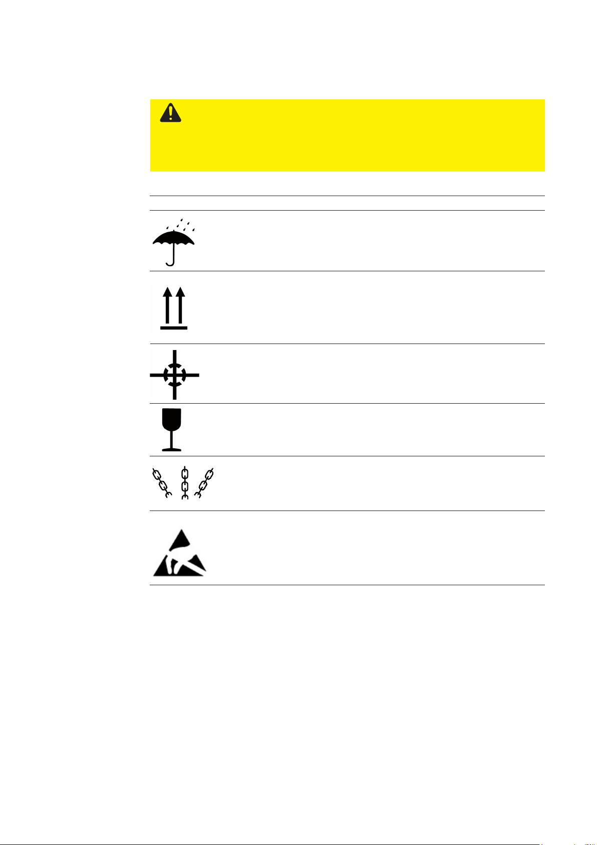
Observe the transport notices on the packaging or box.
Symbol Explanation
Protect from moisture! The shipping item must be kept dry.
Keep upright during transport. Always store and transport shipping items with the arrows pointing upwards. Shipping items must
not be laid on their side or upside-down. If these rules are not
observed, the shipping item may be damaged.
When lifting and transporting a shipping item, note its centre of
gravity. When lifting, always hold the item as close to this point as
possible. This will prevent it from tipping over unexpectedly.
Fragile! Shipping items must always be handled with care.
Attach here! The lifting tackle (lashing chain, hoisting belt) is to be
attached at the indicated points.
Avoid touching packages with this symbol when the relative
humidity is low, especially if wearing insulating footwear or the
oor is non-conductive. Low relative humidity is most common on
warm, dry summer days and very cold winter days.
15
After delivery
Inspect the transport packaging (container, box) for damage.
Important! Fronius International GmbH must be notied immediately of any
damage to the packaging. This will expedite the replacement of any damaged parts.
CAUTION!
Risk of damage to property due to the build-up of condensation.
If parts are not unpacked immediately after delivery, moisture can form on or
inside the parts (condensation). This can lead to serious damage as a result of
the corrosion of parts or to short circuits in electronic/electrical equipment.
Ensure that parts are at room temperature before commissioning. Do not attempt to accelerate this process by exposing the parts to a direct heat source.
If condensation occurs, the parts must not be used until they have dried out
completely (wait ve hours).
Temporary
storage
Transport and
setup
Store the parts in a sheltered place that is dry and free from dust.
Storage conditions:
- Never tip
- Avoid heavy impact
If storing for more than three months:
- Oil exposed parts monthly
- Protect parts from dust and moisture
The total weight of the welding table and system components can be found in the "Machine data" section. The load-carrying equipment used must be designed for this weight.
Check its maximum load before lifting the table.
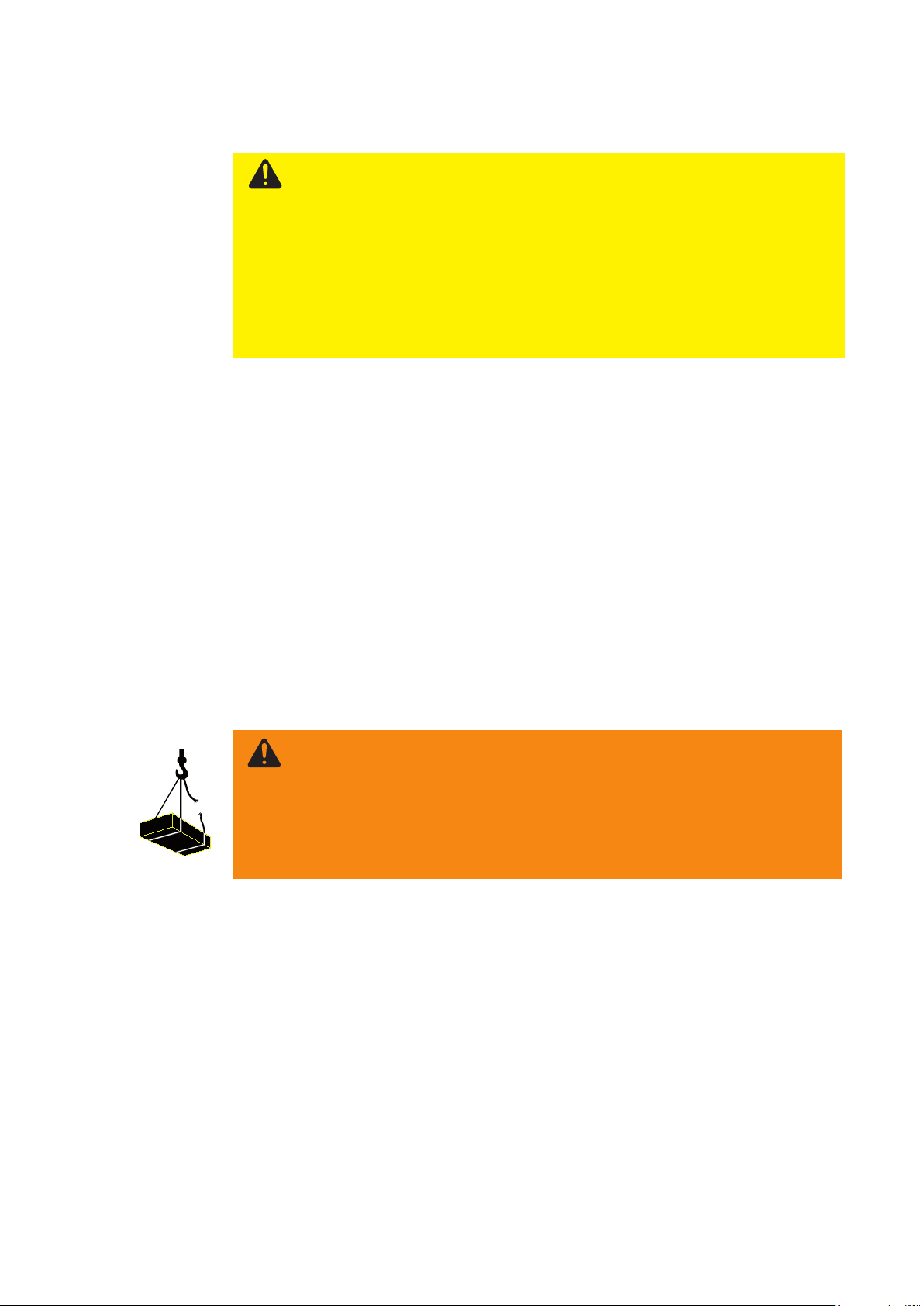
WARNING!
Danger of serious injury from standing under suspended loads
Hoisting, rigging and carrying equipment may be damaged. Falling loads can
cause death or serious injury. Body parts can be crushed, fractured or otherwise injured.
- Never stand under a freely suspended load.
- Make absolutely certain that all attachments are xed and secure before
moving the welding table.
- Only use lifting gear with sucient lifting capacity
- Never use damaged lifting gear
- Do not knot the carrying equipment or lay it over sharp edges
- Always use carrying equipment of the same length
- Move the welding table carefully, avoiding sudden movements
- Set the welding table down carefully
16
Transport and
setup
(continued)
WARNING!
Risk of serious injury and damage from
incorrect lifting and transportation procedures.
Incorrect procedures and unsuitable or incorrect devices can cause serious
injuries and/or damage.
- Observe national regulations when transporting; lifting equipment, ground
conveyors and load-carrying equipment must conform to specications.
- Use the correct load-carrying equipment for transport and assembly
- Only use the lifting lugs or lifting points specied by the manufacturer to
transport the welding table safely.
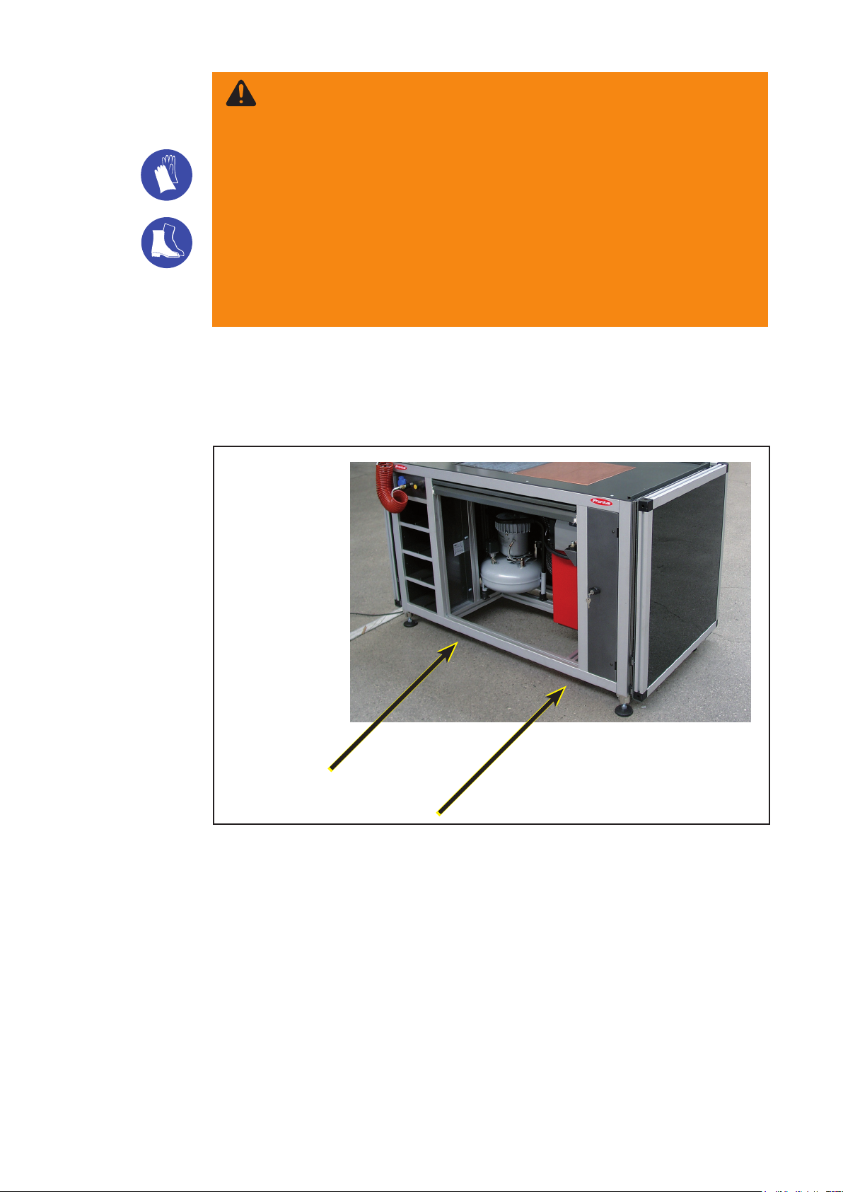
- Wear gloves and safety footwear when moving the welding table or system components
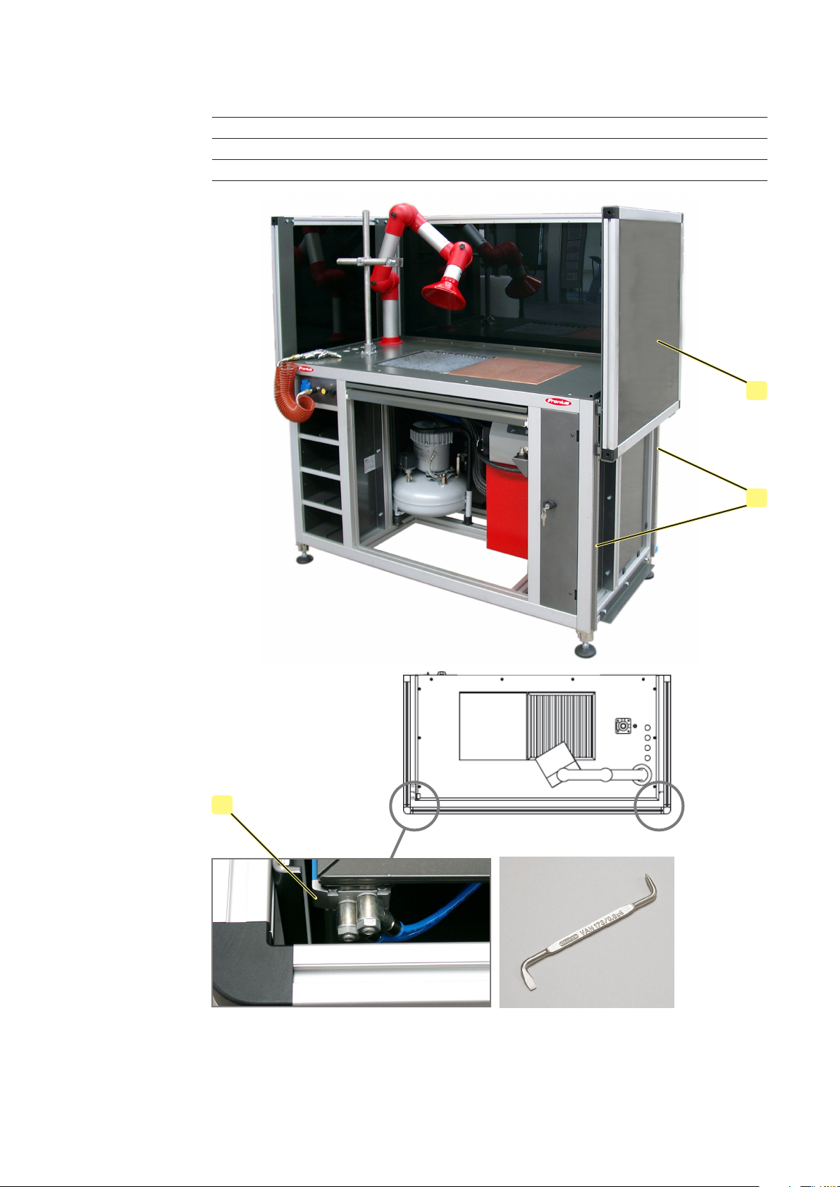
If the table needs to be moved, a forklift truck must be used to pick it up. Ensure that
all connecting leads have been removed. The welding table can also be moved using
(optional) wheels.
FWT 1500x750 welding table, transportation points
17
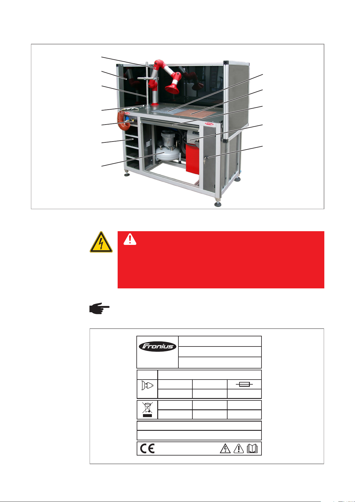
Overview
Overview of the most important functions and features:
Extractor arm
Overhead welding
Control panel
Compartments for
welding samples
Air compressor
Machine data
Welding lter
device
Wire holder
Welding grate
Copper plate
Slag drawer
Fume extractor
Storage area (lockable)
DANGER!
Risk of fatal injury from dangerous electrical voltage.
The areas bearing this symbol contain parts that are under dangerous electrical voltages. An electric shock can be fatal.
Work on the electrical system must only be carried out by qualied
electrical engineers.
NOTE! The rating plates may not be removed or modied without the consent
of Fronius International GmbH. Ensure that the rating plates remain legible.
A-4600 Wels
www.fronius.com
U
3~
50 Hz
FWT 1500x750 welding table, rating plate
400 V
weight
400 kg
Art.No.:
Art.No.:
Ser.No.:
EN 12100-1/-2
1
L x W x H
1600 x 830 x 1140 mm
I1
16 A
max
p
6 bar
FWT 1500
8,045,282
16 A
P1max
11 kVA
18
Description of controls and connections
Safety
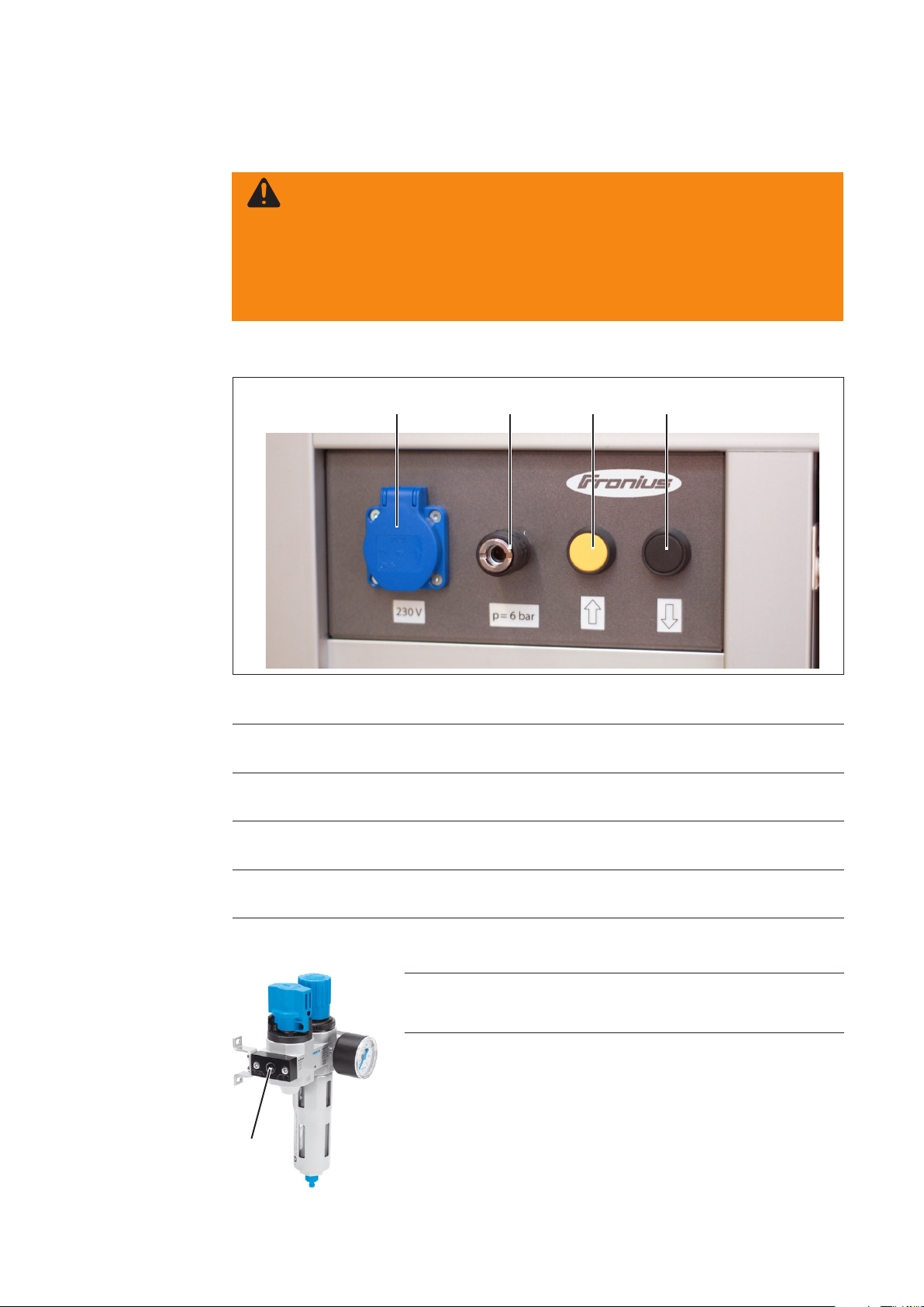
External controls
and connections
WARNING!
Operating the equipment incorrectly can cause serious injury and damage.
Do not use the functions described until you have thoroughly read and understood the following documents:
- these operating instructions
- all operating instructions for the system components
(1)
(2) (3) (4)
Maintenance unit
Control panel
(1) 230V socket
For operating additional tools, such as a portable grinder.
(2) Compressed air
Allows a compressed-air gun to be connected easily using a quick-release coupling.
(3) UP key
For raising the eye protector.
(4) DOWN key
For lowering the eye protector.
(1) Connection on both sides G1/4
Operating pressure 6 bar
(1)
19

Distributor
(1) (2)
(1) 380V socket
Main connection for the welding table
(2) 230V sockets
For operating installed equipment, such as an extractor or compressor
Extractor
Compressor
See extractor operating instructions
See compressor operating instructions
20

Installation and start-up
21

22

Start-up
Properties of the
installation site
Space requirements
Foundations:
- even and rm
Environment:
- not outdoors
- not in a hazardous area
- not in an area of increased electrical risk (including working in boilers, narrow spaces,
in restricted areas, between or on electrically conductive parts, in damp or hot rooms).
E
F
D
C
A
Dimensions
• A 1500 mm
• B 750 mm
• C 945 mm
• D 1780 mm upper position (eye protector)
• D 1140 mm lower position (eye protector)
• E 1600 mm
• F 830 mm
B
23

24

Troubleshooting and maintenance
25

26

Troubleshooting
General
Safety
Basic requirements for the
system to work
In the event of faults, note that the function of the entire system depends on many additional components that are also potential sources of problems.
NOTE! Faults may only be corrected by qualied technicians or by Fronius
service personnel.
WARNING!
An electric shock can be fatal.
Unplug device from the mains before opening it
- Connections established between separate system components
- System components are supplied with electricity and the mains voltage for each
component complies with the rating plate
- Pneumatic system is supplied with compressed air at the correct pressure (see rating
plate)
27

Maintenance, service
Safety
Maintenance
engineers
Maintenance
operations and
intervals
WARNING!
Risk of injury and damage during maintenance work.
Before commencing maintenance work:
- Unplug the welding table from the mains
- Switch o all system components and unplug them from the mains
- Ensure that all moving parts are stationary
WARNING!
Risk of injury and damage from incorrectly performed maintenance.
Maintenance work on the welding table must only be carried out by trained
specialist technicians. It is essential to adhere to the maintenance operations
and intervals. The manufacturer accepts no liability for any damage caused by
inadequate or poorly performed maintenance.
Item Part Action Interval
Linear guides Clean, check oil lm M
A
Threaded spindle Clean, regrease M
B
Rack and pinion Clean, regrease M
C
D
Toothed belt Pretension, check for tears M
Current collector Clean, apply conductive paste M
E
Earth cable Check connection M
F
Rollers and rails Clean, check position M
G
H
Maintenance units Check lter element and M
If dirty, change; check liquid level
Pneumatic/hydraulic systems Check interconnecting hosepacks and M
I
connections, Check guide rods for dirt and check
oil lm, check maintenance unit
J
Linear and Clean, function test M
rotating components
Safety measures: Function test D
K
(EMERGENCY STOP, limit switches,
safety strips)
L
Bearing units, bearing blocks Regrease M
M
Lubricating nipple Regrease M
N
Filter mats, ventilation slots Clean W
O
Safety glass Check for damage, replace if necessary M
D ..........Daily
W .........Weekly
M .........Monthly
½Y.......Twice per year
Y .........Annually
28
Recommended
lubricants
Important! Lubricants with solid lubricant additives (e.g. MoS2, graphite and PTFE) are
not suitable for guiding systems.
Lubricant DIN DIN number Remarks
Lubricating grease KP 2-K 51502 / 51825 Lithium soap-based grease
Lubricating oil CLP32-100 51517 Part 3 ISO VG 32-100
O
Safety glass speed can be
adjusted by repositioning
the exhaust air choke using
an angled screwdriver
I
A
Angled screwdriver
Important! The maintenance activities and maintenance intervals of the following system
components can be found in the relevant operating instructions:
- Compressor
- Fume extractor
29
Spare parts & accessories
Ordering
details
Spare parts
NOTE! Only trained technicians may change parts and may only do so after
consulting the installation and dismantling instructions supplied.
When ordering spare parts, please provide the following data:
- Exact designation of the spare part
- Associated item number as per spare parts list
- Model name of the device
- Serial number (shown on the rating plate)
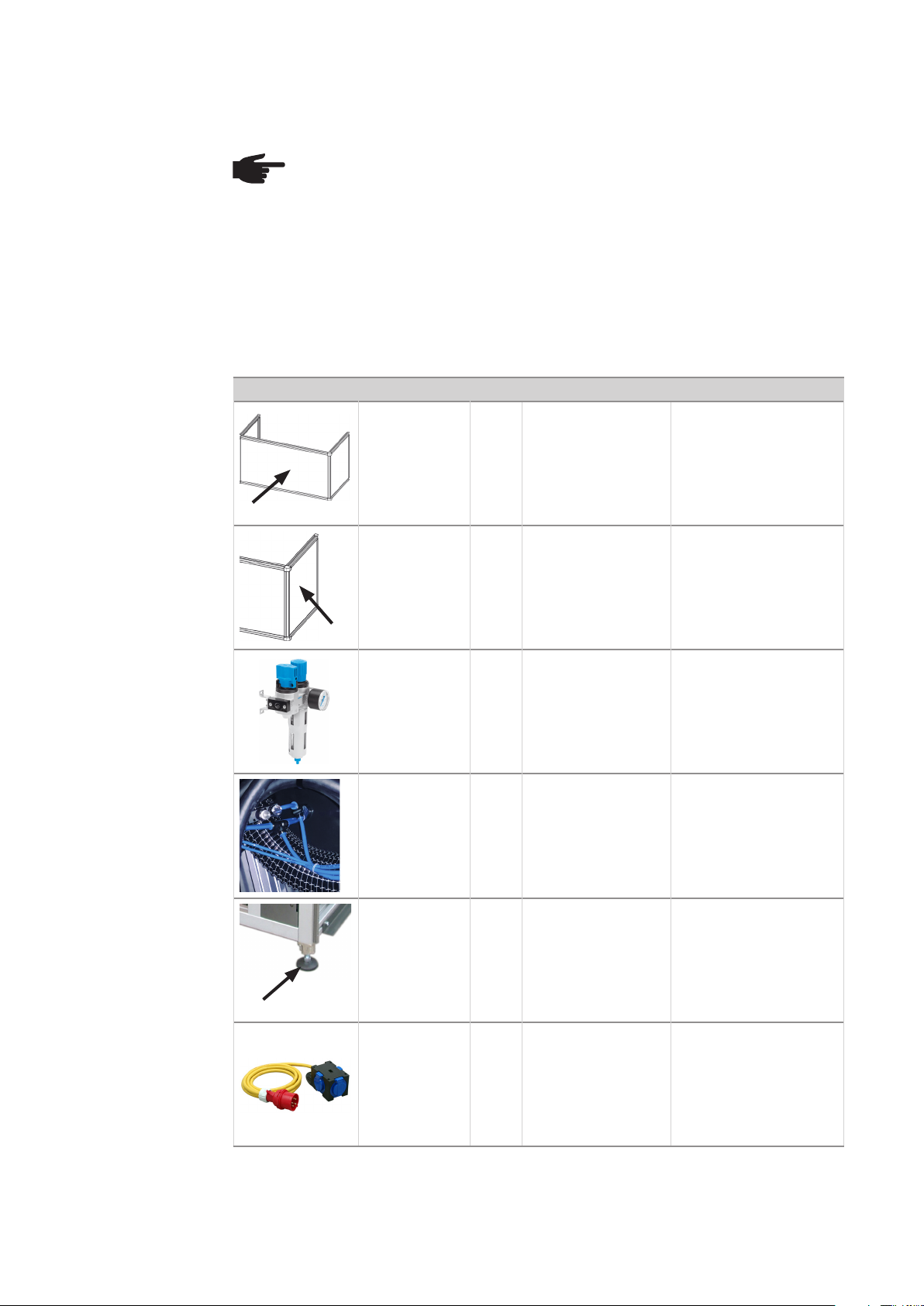
Photo Item no. No. Type Description
58,0223,2411 1 Safety glass, front
58,0223,2410 1 Safety glass, side
48,0001,0083 1 0.3-10 G1/4 Maintenance unit
38,0003,0266 1 0.3-10 G1/4
48,0007,0202 1 80 / M16x68 Machine foot
38,0008,0030 1 16A / 400V Current distribution box
Pressure regulating
valve
30
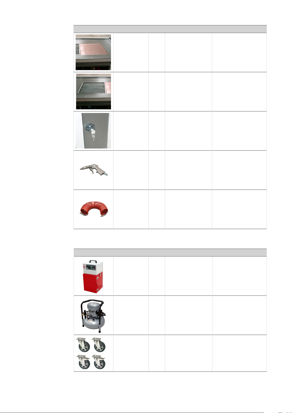
Spare parts
(continued)
Photo Item no. No. Type Description
48,0002,0198 1 Copper plate
58,0223,4000 1 Welding grate
Accessories
48,0007,0199 1
Lever cylinder lock
(incl. 2 keys)
48,0001,0114 1 Blow-through gun
48,0001,0113 1 DM6 7.5m
Spiral hose (pneumatic)
Photo Item no. No. Type Description
Fume extractor (incl.
8,100,119 1
extractor arm, extractor hood, automatic
start/stop)
8,100,120 1
8,100,0121 1
31
2x castors
2x castors with
locks
Air compressor (incl.
blow-through gun and
spiral hose)
Wheels incl. installation materials
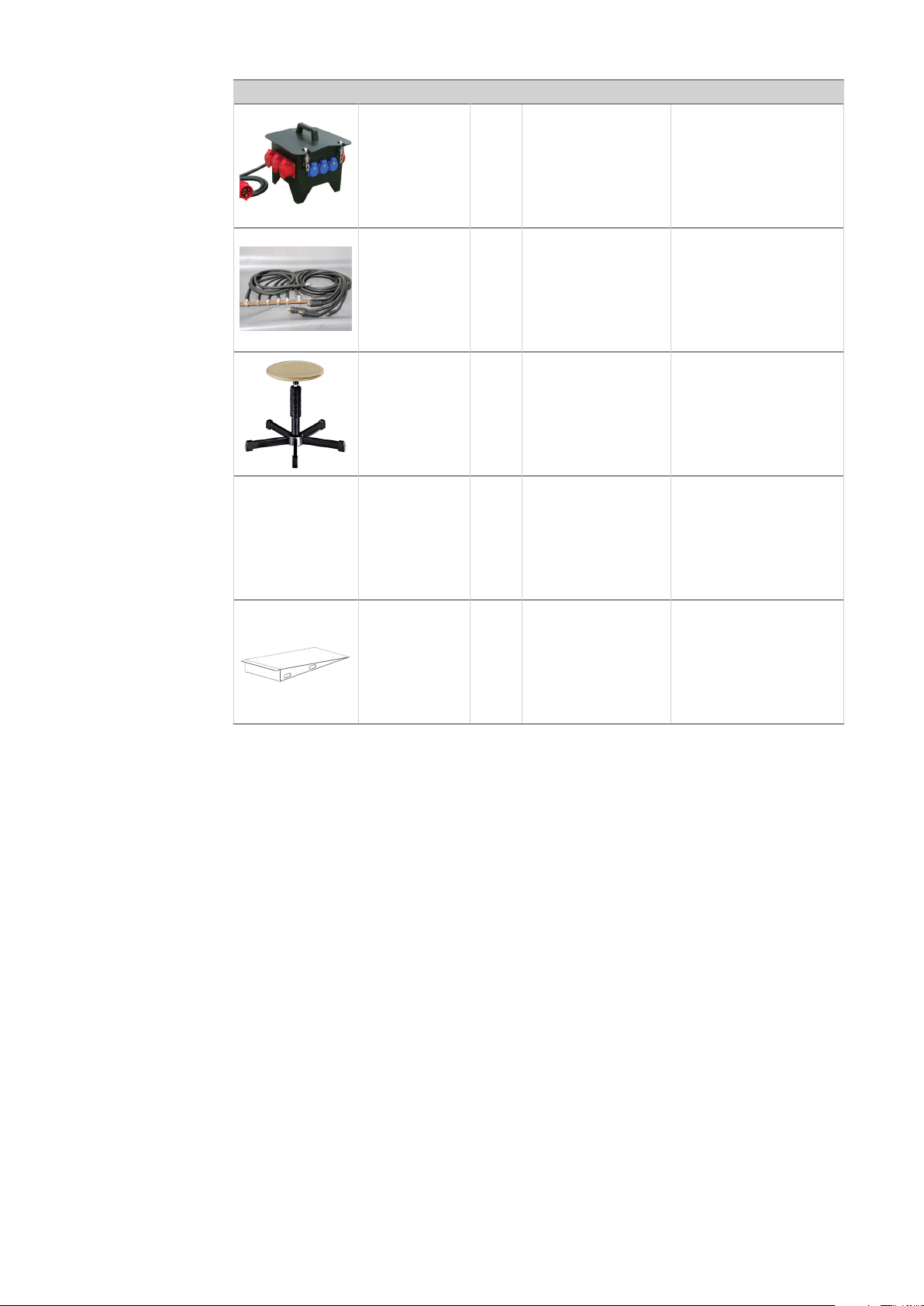
Accessories
(continued)
Photo Item no. No. Type Description
no image
38,0008,0027 1 32A / 400V
38,0100,0189 1
48,0009,0038 1
on request 1
country-specic
version
Current connection
distributor
Earth cable distributor
(x5)
Swivel stool (symbol
photo)
Transport box
58,0223,F000 1
Ramp (for transport
box)
32

Annex
33

34

Declaration of conformity
35

36

Pneumatic plan
37

38

'*&.339$*.
=.%
33/
*5/$46'
26%
/50$46
9/%
6926
7*(
696
76:
39

FRONIUS INTERNATIONAL GMBH
TechSupport Automation
www.fronius.com
www.fronius.com/addresses
40
 Loading...