


Operating
Instructions
Fronius Tauro 50-3
Fronius Tauro ECO 50-3
Fronius Tauro ECO 99-3
Fronius Tauro ECO 100-3
Operating Instructions
EN
42,0426,0307,EN 028-23022023


Contents
Safety rules 6
Explanation of safety notices 6
General 6
Environmental conditions 7
Qualified personnel 7
Safety measures at the installation location 7
Noise emission values 7
EMC measures 7
Data protection 8
Copyright 8
Protective earthing (PE) 8
Maintenance 8
General information 9
Description of the device 11
Description of the device 11
AC Daisy Chain 11
String fuses 11
Fronius Solar.web 12
Local communication 13
Protection of people and equipment 14
Safety 14
Warning notices and rating plate on the device 14
WSD (wired shutdown) 15
Central grid and system protection 15
RCMU 15
Surge protective device 16
Surge protective device (SPD) 16
AFCI – Arc Fault Circuit Interrupter (ArcGuard) 16
Safe state 17
Proper use 18
Intended use 18
Regulations governing the photovoltaic system 18
Functional principle 19
Functional principle 19
Cooling of the inverter through forced-air ventilation 19
Power derating 19
Control elements and connections 20
Controls and displays 20
PV connections - Tauro 50-3-D (direct) 20
PV connections - Tauro Eco 50-3-D (direct) 21
PV connections - Tauro 50-3-D (30A fuses) 21
PV connections - Tauro Eco 50-3-D (30A fuses) 21
PV connections - Tauro Eco 99-3-D / 100-3-D (direct, 20 A option) 22
PV connections - Tauro Eco 99-3-D / 100-3-D (direct, 30 A option) 22
PV connections - pre-combined 22
Optional DC disconnector lock 23
Mounting option for third-party components 23
Data communication area in the inverter 23
Data communication area 24
Internal schematic connection diagram of the IOs 25
Button functions and LED status indicator 26
EN
Installation and commissioning 29
General 31
System component compatibility 31
Installation location and position 32
Choosing the location of the inverter 32
3

Installation position 33
Transport 35
Crane transport 35
Transporting by counterbalanced lift truck or lift truck 35
Mounting the inverter 36
Selecting the fixing material 36
Mounting bracket dimensions 36
Mounting the inverter on the wall 36
Mounting the inverter on floor racks 38
Connecting the inverter to the public grid (AC side) 39
Monitoring the grid 39
AC connection area 39
Connecting aluminium cables 40
Permitted cables 40
Maximum alternating current fuse protection 41
Changing the clamping area for V-type terminal 42
Additional PE introduction for earthing 42
Safety 43
Opening the inverter 43
Switching off the AC disconnector option 44
Connecting the inverter to the public grid - Singlecore 44
Connecting the inverter to the public grid - Multicore 45
Connecting the inverter to the public grid - Daisy Chain 47
Connecting cables with a cable lug 48
Connecting the PV cable to the inverter 50
Safety 50
General comments regarding PV modules 51
Permitted cables 51
DC fuse protection - pre-combined 52
Example of Fronius Tauro Eco 50-3-P / 99-3-P / 100-3-P combiner box 53
Example Fronius Tauro 50-3-P combiner box 54
Distribution of the solar module strings for the direct version 54
Connecting PV cables - MC4 connector 55
MC4 connector cover 55
Connecting PV cables - Pre-combined 56
Connecting cables with a cable lug 57
Replacing the string fuses 58
Closing and switching on the inverter 60
Connecting the data communication cable 62
Modbus participants 62
Permitted cables for the data communication area 62
Multiple inverters in one network 63
Routing data communication cables 63
WSD (wired shutdown) 65
Using for the first time 67
Starting the inverter for the first time 67
Fronius system monitoring (Pilot) display 67
Installation with the app 67
Installation using the web browser 68
Switching off current supply and restarting the inverter 70
De-energising the inverter and switching it on again 70
Settings - user interface of the inverter 71
User settings 73
User login 73
Selecting the language 73
Device configuration 74
Components 74
Functions and IOs 74
"PSC editor - AUS - Demand Response Modes (DRM)" 75
Demand Response Modes (DRM) 75
4

Inverter 75
System 77
General 77
Update 77
Setup wizard 77
Restoring the factory settings 77
Event log 77
Information 77
Licence manager 78
Support 79
Communication 80
Network 80
Modbus 81
Remote control 82
Fronius Solar API 82
Safety and grid requirements 83
Country setup 83
Feed-in limitation 83
I/O power management 84
Connection diagram - 4 relay 85
I/O power management settings - 4 relays 86
Connection diagram - 3 relay 87
I/O power management settings - 3 relays 88
Connection diagram - 2 relay 89
I/O power management settings - 2 relays 90
Connection diagram - 1 relay 91
I/O power management settings - 1 relay 92
EN
Appendix 93
Status codes and remedy 95
Status Codes 95
Technical data 96
Tauro 50-3-D / 50-3-P 96
Tauro Eco 50-3-D / 50-3-P 98
Tauro Eco 99-3-D / 99-3-P 100
Tauro Eco 100-3-D / 100-3-P 102
WLAN 105
Explanation of footnotes 105
Integrated DC disconnector 105
Applicable standards and guidelines 107
CE mark 107
WLAN 107
Power failure 107
Service, warranty terms and conditions and disposal 108
Fronius SOS 108
Fronius manufacturer's warranty 108
Disposal 108
5

Safety rules
Explanation of
safety notices
Indicates a potentially hazardous situation.
▶
Indicates a situation where damage could occur.
▶
Indicates a risk of flawed results and possible damage to the equipment.
If you see any of the symbols depicted in the "Safety rules" chapter, special care
is required.
General The device has been manufactured in line with the state of the art and according
to recognised safety standards. In the event of incorrect operation or misuse,
there is a risk of:
-
-
WARNING!
If not avoided, death or serious injury may result.
CAUTION!
If not avoided, minor injury and/or damage to property may result.
NOTE!
Injury or death to the operator or a third party
Damage to the device and other material assets belonging to the operator
All personnel involved in commissioning and maintenance of the device must:
Be suitably qualified,
-
Have knowledge of and experience in dealing with electrical installations and
-
Read and follow these Operating Instructions carefully.
-
In addition to the Operating Instructions, all applicable local rules and regulations regarding accident prevention and environmental protection must also be
followed.
All safety and danger notices on the device:
Must be kept in a legible state
-
Must not be damaged
-
Must not be removed
-
Must not be covered, pasted or painted over
-
Only operate the device when all protection devices are fully functional. If the
protection devices are not fully functional, there is a risk of:
Injury or death to the operator or a third party
-
Damage to the device and other material assets belonging to the operator
-
Any safety devices that are not fully functional must be repaired by an authorized specialist before the device is switched on.
Never bypass or disable protection devices.
For the location of the safety and danger notices on the device, refer to the
chapter headed "Warning notices on the device" in the Operating Instructions for
your device.
6

Faults that could compromise safety must be remedied before switching on the
device.
EN
Environmental
conditions
Qualified personnel
Operation or storage of the device outside the stipulated area will be deemed as
not in accordance with the intended purpose. The manufacturer accepts no liability for any damage resulting from improper use.
The servicing information contained in these Operating Instructions is intended
only for the use of qualified service engineers. An electric shock can be fatal. Do
not carry out any actions other than those described in the documentation. This
also applies to qualified personnel.
All cables and leads must be secured, undamaged, insulated, and adequately dimensioned. Loose connections, scorched, damaged or inadequately dimensioned
cables and leads must be immediately repaired by authorised personnel.
Repair work must only be carried out by authorised personnel.
It is impossible to guarantee that bought-in parts are designed and manufactured to meet the demands made on them, or that they satisfy safety requirements. Use only original spare parts (also applies to standard parts).
Do not carry out any alterations, installations, or modifications to the device
without first obtaining the manufacturer's permission.
Components that are not in perfect condition must be changed immediately.
Safety measures
at the installation location
Noise emission
values
EMC measures In certain cases, even though a device complies with the standard limit values for
When installing devices with openings for cooling air, ensure that the cooling air
can enter and exit unhindered through the air ducts. Only operate the charger in
accordance with the degree of protection shown on the rating plate.
The sound power level of the inverter is specified in the Technical data.
The device is cooled as quietly as possible with the aid of an electronic temperature control system; this depends on the amount of converted power, the ambient
temperature, the level of soiling of the device, etc.
It is not possible to provide a workplace-related emission value for this device
because the actual sound pressure level is heavily influenced by the installation
situation, the grid quality, the surrounding walls and the properties of the room
in general.
emissions, it may affect the application area for which it was designed (e.g., when
there is equipment that is susceptible to interference at the same location, or if
the site where the device is installed is close to either radio or television receivers). If this is the case, then the operator is obliged to take appropriate action to
rectify the situation.
7

Data protection The user is responsible for the safekeeping of any changes made to the factory
settings. The manufacturer accepts no liability for any deleted personal settings.
Copyright Copyright of these operating instructions remains with the manufacturer.
The text and illustrations are all technically correct at the time of printing. We
reserve the right to make changes. The contents of the operating instructions
shall not provide the basis for any claims whatsoever on the part of the purchaser. If you have any suggestions for improvement, or can point out any mistakes that you have found in the instructions, we will be most grateful for your
comments.
Protective
earthing (PE)
Maintenance In principle, Tauro inverters are maintenance-free. If maintenance work is never-
Connection of a point in the device, system or installation to earth to protect
against electric shock in the event of a fault. When installing the Tauro inverter,
the PE connection is mandatory as it is a protection class 1 device. When connecting the PE conductor, ensure that it is secured against accidental disconnection. All points listed under "Connecting the inverter to the public grid (AC side)"
must be observed, including the use of washers, screw locks, and nuts with the
defined torque.
It must be ensured that when using the strain-relief devices, the ground conductor is the last to be disconnected in the event of a possible failure. When connecting the ground conductor, the minimum cross-section requirements specified by the respective national regulations must be observed. In addition, the
minimum cross-section of the PE conductor must be at least half of the phase
cross-sections according to the product standard IEC 62109-1, as a cross-section of at least 35 mm² (50 kW) or 70 mm² (99.99 / 100 kW) must be used for the
phases (L1 / L2 / L3).
theless carried out on the inverter, such as cleaning or replacing components,
this must be done in consultation with a Fronius-trained service technician. The
manufacturer accepts no liability for damage caused by improper use.
8

General information
9

10

Description of the device
EN
Description of
the device
AC Daisy Chain With the "AC Daisy Chain" inverter version, the AC lead can be fed directly from
The inverter transforms the direct current generated by the solar modules into
alternating current. This alternating current is fed into the public grid synchronously with the grid voltage.
The inverter has been developed exclusively for use in grid-connected photovoltaic systems; it is impossible to generate energy independently of the public grid.
Thanks to its design and the way it works, the inverter is extremely safe both to
install and to operate.
The inverter automatically monitors the public grid. In the event of abnormal grid
conditions, the inverter ceases operating immediately and stops feeding power
into the grid (e.g. if the grid is switched off, if there is an interruption, etc.).
The grid is monitored by monitoring the voltage, frequency and islanding conditions.
the inverter to another inverter. Several Tauro inverters, up to an output power of
max. 200 kW, can be thereby be quickly connected to one another.
The minimum cable cross-section is defined by the fuse at the mains connection
point. A larger cable cross-section can be selected at any time. The applicable
national standards must be taken into account and applied.
String fuses Only applies to device types Fronius Tauro 50-3-D / Eco 50-3-D / Eco 99-3-D /
Eco 100-3-D (direct):
String fuses are used in the Fronius Tauro to provide additional protection for the
solar modules.
The maximum short circuit current Isc, the maximum module return current IR or
the maximum string fuse rating specified in the module data sheet of the respective solar module is crucial in affording the solar modules the correct fuse
protection.
The national regulations regarding fuse protection must be observed. The electrical engineer carrying out the installation is responsible for the correct choice
of string fuses.
11

To replace the string fuses, see chapter Replacing the string fuses on page 58.
Eco 50-3-D
Eco 99-3-D / Eco 100-3-D Standard
F1.1 - F2.7
Eco 99-3-D / Eco 100-3-D
Standard
F3.1 - F3.8
50-3-D
F1.1 - F3.7
F3.1-
F3.1+
F3.2-
F3.2+
F3.3-
F3.3+
F3.4-
F3.4+
F3.5-
F3.5+
Eco 50-3-D
30A fuses F1.1 - F2.5
50-3-D / Eco 99-3-D / Eco 100-3-D
30A fuses F1.1 - F3.5
Fronius Solar.web
With Fronius Solar.web or Fronius Solar.web Premium, the PV system can be
easily monitored and analysed by the system owner and installer. If configured
accordingly, the inverter transmits data such as power, yields, load, and energy
balance to Fronius Solar.web. For more information see Solar.web - monitoring &
analysis.
Configuration is carried out via the setup wizard, see chapter Installation with
the app on page 67 or Installation using the web browser on page 68.
12

Prerequisites for configuration:
Internet connection (download: min. 512 kBit/s, upload: min. 256 kBit/s)*.
-
User account on solarweb.com.
-
Completed configuration via the setup wizard.
-
* The information given does not constitute an absolute guarantee of fault-
less function. High error rates in the transmission, reception fluctuations
or transmission drop-outs can have a negative effect on the data transfer.
Fronius recommends testing the Internet connection on site according to
the minimum requirements.
EN
Local communication
The inverter can be found via the Multicast DNS protocol (mDNS). It is recommended to search for the inverter by the assigned host name.
The following data can be retrieved via mDNS:
NominalPower
-
Systemname
-
DeviceSerialNumber
-
SoftwareBundleVersion
-
13

Protection of people and equipment
Safety
Warning notices
and rating plate
on the device
WARNING!
Danger due to incorrect operation and incorrectly performed work.
This can result in serious injury and damage to property.
All the work and functions described in this document must only be carried
▶
out by trained and qualified personnel.
Read and understand this document.
▶
Read and understand all the Operating Instructions for the system compon-
▶
ents, especially the safety rules.
WARNING!
Danger from electromagnetic fields. Electromagnetic fields are generated during operation.
Effects on the health of persons, e.g. those wearing a pacemaker can result.
Do not remain closer than 20 cm from the inverter for a prolonged period of
▶
time.
There are warning notices and safety symbols on and in the inverter. These warning notices and safety symbols must not be removed or painted over. They warn
against incorrect operation, as this may result in serious injury and damage.
Symbols on the rating plate:
CE mark – confirms compliance with applicable EU directives and
regulations.
UKCA mark – confirms compliance with applicable UK directives and
regulations.
A 4-digit number (coded production
date) is printed at the very bottom of
the rating plate, from which the production date can be calculated.
If you subtract the value 11 from the
first two digits, you get the production
year.
The last two digits represent the calendar week in which the device was produced.
Example: Value on rating plate = 3205
32 - 11 = 21 → Production year 2021
05 = Calendar week 05
14
WEEE mark – waste electrical and electronic equipment must be
collected separately and recycled in an environmentally sound manner
in accordance with the European Directive and national law.

RCM mark – tested in accordance with the requirements of Australia
and New Zealand.
ICASA mark – tested in accordance with the requirements of the
Independent Communications Authority of South Africa.
CMIM mark – tested in accordance with IMANOR requirements for
import regulations and compliance with Moroccan standards.
Safety symbols:
Risk of serious injury and property damage due to incorrect operation.
Do not use the functions described here until you have fully read and
understood the following documents:
These Operating Instructions.
-
All Operating Instructions for the system components of the
-
photovoltaic system, especially the safety rules.
Dangerous electrical voltage.
Before opening the machine, wait for the capacitors to discharge!
Text of the warning notices:
EN
WSD (wired
shutdown)
Central grid and
system protection
WARNING!
An electric shock can be fatal. Before opening the device, ensure that the input
and output sides are de-energised and insulated.
The wired shutdown (WSD) interrupts the inverter feeding energy into the grid if
the trigger device (switch, e.g. emergency stop or fire alarm switch) has been activated.
If an inverter (secondary device) fails, it is bypassed and the other inverters continue operating. If a second inverter (secondary device) or the inverter (primary
device) fails, the operation of the entire WSD chain is interrupted.
For installation, see WSD (wired shutdown) on page 65.
The inverter offers the option to use the integrated AC relays as coupling
switches in conjunction with a central grid and system protection unit (in accordance with VDE-AR-N 4105:2018:11 §6.4.1). For this purpose, the central trigger
device (switch) must be integrated into the WSD chain as described in the
chapter "WSD (Wired Shut Down)".
RCMU The inverter is equipped with a universal current-sensitive residual current monit-
oring unit (RCMU = Residual Current Monitoring Unit) in accordance with IEC
62109-2 and IEC63112.
This device monitors residual currents from the PV module to the AC output of
the inverter and disconnects the inverter from the grid in the event of unauthorised residual current.
15

Surge protective
device
The inverter is equipped with an integrated surge protective device on the DC
and AC side in accordance with IEC 62109-2. The surge protective device protects the system against damage in the event of a surge.
Surge protective
device (SPD)
AFCI – Arc Fault
Circuit Interrupter (ArcGuard)
The surge protective device (SPD) protects against temporary overvoltages and dissipates surge currents (e.g. lightning strike). Building on
an overall lightning protection concept, the SPD helps to protect your
PV system components.
If the surge protective device is triggered, the colour of the indicator
changes from green to red (mechanical display).
There is the option of a digital indication when an SPD has tripped. For
setting this function, see PDF "Temporary SPD Triggering" in the Service
& Support area at www.fronius.com
IMPORTANT!
After setting the function described above, the inverter will also respond if the 2pole signal cable of the surge protective device is interrupted or damaged.
Available ex works.
AFCI (Arc Fault Circuit Interrupter) protects against arcing faults and in the narrower sense is a protection device against contact faults. The AFCI evaluates any
faults that occur in the current and voltage curve with an electronic circuit and
switches off the circuit when a contact fault is detected. This prevents overheating on poor contacts and possible fires.
IMPORTANT!
Active solar module electronics can interfere with the function of the ArcGuard.
Fronius does not guarantee the correct functioning when using Fronius ArcGuard
in combination with active solar module electronics.
CAUTION!
Danger due to incorrect or unprofessional DC installation.
This can result in risk of damage and, in turn, risk of fire to the PV system due to
inadmissible thermal loads that arise with an arc.
Check that plug connections are in good condition.
▶
Repair incorrect insulation as appropriate.
▶
Complete connections as per the specifications.
▶
IMPORTANT!
Fronius will not accept any costs associated with production downtimes, installer
costs, etc., that may arise as the result of a detected arc and its consequences.
Fronius accepts no liability for damage that can occur despite the presence of
the integrated Arc Fault Circuit Interrupter/extinguishing system ( e.g. caused by
a parallel arc).
Automatic reconnection
To restart the AFCI, no manual procedure is required if a minimum interruption
time of 5 minutes is ensured before continuing operation.
When interrupting for the fifth time within a 24 h period, the AFCI is only allowed to be reset manually before the AFCI does reconnect. Afterwards, the
AFCI may return to automatic reconnection mode.
16

Safe state If one of the following safety devices trips, the inverter will change to a safe
state:
WSD
-
isolation measurement
-
RCMU and
-
AFCI
-
In the safe state, the inverter no longer feeds into the grid and is disconnected
from the grid by opening the AC relays.
EN
17

Proper use
Intended use The solar inverter is intended exclusively to convert direct current from solar
modules into alternating current and to feed this into the public grid.
Utilisation not in accordance with the intended purpose comprises:
Utilisation for any other purpose, or in any other manner
-
Making any modifications to the inverter that have not been expressly ap-
-
proved by Fronius
Installation of parts that are not distributed or expressly approved by Froni-
-
us
The manufacturer shall not be liable for any damage resulting from such use. All
warranty claims will be forfeited.
Intended use also includes complying with all the instructions in the Operating
Instructions.
Regulations governing the
photovoltaic system
The inverter is designed to be connected and used exclusively in conjunction with
solar modules.
Use of the inverter with other DC generators (e.g. wind generators) is not permitted.
When designing the photovoltaic system, ensure that all of its components are
operated within their permitted operating ranges at all times.
Observe all the measures recommended by the solar module manufacturer to
ensure that the solar module retains its properties in the long term.
18

Functional principle
EN
Functional principle
Cooling of the
inverter through
forced-air ventilation
The inverter operates fully automatically. As soon after sunrise as there is sufficient energy available from the solar modules, the inverter starts checking the
PV system (insulation measurement), and the grid (grid voltage and grid frequency). If all values are within the normative scope, automatic connection to the
grid and feeding of energy into the grid takes place.
The inverter works in a way that ensures the maximum power possible is obtained
from the solar modules. This is known as "Maximum Power Point Tracking"
(MPPT). In the event of shading of the solar modules, the function "Dynamic
Peak Manager" can be used to obtain the majority of the local maximum output
(LMPP) of the PV system.
After dusk, as soon as the power available has fallen below the level at which energy can be fed into the grid, the inverter disconnects the power electronics
completely from the grid and stops running. It retains all its settings and stored
data.
Cooling of the inverter is performed by a forced-air ventilation system via temperature-controlled fans. Air is sucked in from the front and fed, via a sealed
duct, through the AC and DC heat sink, before passing directly over the inductors and dissipating.
The sealed air duct prevents the electronics compartment from coming into contact with the ambient air. This approach largely prevents any contamination of
the electronics compartment.
The fan speed and temperature of the inverter are monitored.
The variable-speed, ball-bearing mounted fans in the inverter permit the following:
Optimum cooling of the inverter
-
Cooler components, therefore a longer service life
-
Lowest-possible energy consumption
-
High output power including in top temperature range of the inverter
-
Power derating If the inverter becomes too hot, it automatically reduces the current output
power in order to protect itself. Reasons for the inverter becoming too hot include too high an ambient temperature or inadequate heat dissipation (e.g. when
installed in containers without proper heat dissipation measures).
A power derating system restricts the output from the inverter in order to prevent the temperature from exceeding the permissible value.
If a maximum temperature is exceeded, the inverter switches off in a safe state
and does not resume feeding energy into the grid until the device has cooled
down.
19

Control elements and connections
Controls and displays
(1) DC disconnector
Disconnects the electrical connection from the solar modules
to the inverter. Depending on
the device type, 2 or 3 DC disconnectors are installed.
The DC disconnectors can be
secured against switching on
with a padlock.
(2) AC disconnector option
The optional AC disconnector
breaks the connection from the
inverter to the grid
(3) Button function
For further information about
the button function, see But-
ton functions and LED status
indicator
(4) LED status indicator
For further information about
the LED status indicator, see
Button functions and LED
status indicator
PV connections Tauro 50-3-D
(direct)
20

PV connections Tauro Eco 50-3D (direct)
PV connections Tauro 50-3-D
(30A fuses)
EN
PV connections Tauro Eco 50-3D (30A fuses)
21

PV connections Tauro Eco 99-3D / 100-3-D (direct, 20 A option)
PV connections Tauro Eco 99-3D / 100-3-D (direct, 30 A option)
PV connections pre-combined
22
Tauro Eco 50-3-P / 99-3-P / 100-3-P Tauro 50-3-P

Optional DC disconnector lock
With the optionally available DC disconnector lock, the inverter can be secured against unintentional switching
off.
EN
Mounting option
for third-party
components
Data communication area in the
inverter
Above the DC connection area there is
space for mounting third-party components. Components up to a maximum width of 14.5 cm (8 DU) can be
mounted on the DIN rail. The components must have a temperature resistance of ‑40 °C to +85 °C.
The data communication area (Pilot PC board) is located above the DC connections in the inverter.
23

Data communication area
Modbus terminal Push-in terminal for the installation of
Modbus 0, Modbus 1, 12 V and GND
(ground).
The data connection to the connected
components is established via the
Modbus terminal. The inputs M0 and
M1 can be selected for this purpose.
Max. 4 Modbus participants per input,
see chapter Modbus participants on
page 62.
WSD (wired shutdown) switch Defines the inverter as a WSD primary
device or WSD secondary device.
Position 1: WSD primary device
Position 0: WSD secondary device
Modbus 0 (MB0) switch Switches the terminating resistor for
Modbus 0 (MB0) on/off.
Position 1: Terminating resistor on
(factory setting)
Position 0: Terminating resistor off
Modbus 1 (MB1) switch Switches the terminating resistor for
Modbus 1 (MB1) on/off.
Position 1: Terminating resistor on
(factory setting)
Position 0: Terminating resistor off
Optical sensor
Communication LED
To operate the inverter. See chapter
Button functions and LED status indicator on page 26.
Indicates the inverter connection
status.
24
Operating status LED
Indicates the inverter operating
status.

LAN 1 Ethernet connection for data commu-
nication (e.g. WLAN router, home network or for commissioning with a
laptop see chapter Installation using
the web browser on page 68).
LAN 2 Reserved for future functions. Only
use LAN 1 to avoid malfunctions.
WSD terminal Push-in terminal for the WSD installa-
tion. See chapter "WSD (wired shut-
down)" on page 65.
IOs terminal Push-in terminal for digital inputs/
outputs. See chapter Permitted
cables for the data communication
area on page 62.
The designations (RG0, CL0, 1/5, 2/6,
3/7, 4/8) on the terminal refer to the
Demand Response Mode function, see
chapter "PSC editor - AUS - Demand
Response Modes (DRM)" on page 75.
EN
Internal schematic connection
diagram of the
IOs
On the V+/GND pin, it is possible to feed in a voltage of around 12.5–24 V (+ max.
20%) with an external power supply. The outputs IO 0–5 can then be operated
with the external voltage. A maximum of 1 A can be drawn per output, with a
maximum of 3 A allowed in total. The fuse protection must be located externally.
CAUTION!
Risk of polarity reversal at the terminals due to improper connection of external
power supplies.
This may result in severe damage to the inverter.
Check the polarity of the external power supply with a suitable measuring
▶
device before connecting it.
Connect the cables to the V+/GND outputs with the correct polarity.
▶
IMPORTANT!
If the total output (6 W) is exceeded, the inverter switches off the entire external
power supply.
25

12 V DC
500 mA
V+ V+
GND
IO0
IO1
IN8
IN9
IN10
IN11
IN6
IN7
IO4
IO5
IO2
IO3
GND
(1)
12 V
USB
TYP A
5 V
IO4
V+
V+
IO0
IO2
IN6
IN8
IN10IN11
IN9
IN7
IO5
IO3
IO1
GND
GND
M0-
M0+
M1-
M1+
SHIELD
SHIELD
V+ V+
GND GND
V+
V+
M0+
SHIELD
M1+
GND
M1-
SHIELD
M0-
GND
(1) Power limitation
Ok
Standby
Uncritical Error
(flashing)
Critical Error
Network Error
Connecting
(flashing)
Connected
1x WLAN access point
2x WPS
3-6 sec. Quit Service Message
Button functions
and LED status
indicator
Sensor functions
The status of the inverter is
shown via the operating status
LED. In the event of faults,
carry out the individual steps
in the Fronius Solar.web live
app.
The optical sensor is actuated
by touching with a finger.
The status of the connection is
shown via the communication
LED. To establish the connection, carry out the individual
steps in the Fronius Solar.web
live app.
1x = WLAN access point (AP) is opened.
Flashing blue
26
2x = WLAN Protected Setup (WPS) is activated.
Flashing green
3 seconds (max. 6 seconds) = the service notification is
terminated.
Lights up yellow

LED status indicator
The inverter is operating correctly.
Lights up green
The inverter starts.
Flashing green
The inverter is in standby, is not operational (e.g. no
feed-in at night) or is not configured.
Lights up yellow
The inverter indicates a non-critical status.
Flashing yellow
The inverter indicates a critical status and there is no
grid power feed process.
Lights up red
The network connection is being established via WPS.
2x = WPS search mode.
EN
Flashing green
The network connection is being established via
WLAN AP.
1x = WLAN AP search mode (active for 30 minutes).
Flashing blue
The network connection is not configured.
Lights up yellow
The inverter is operating correctly, a network fault is in-
dicated.
Lights up red
The inverter is performing an update.
/ Flashing blue
27

28

Installation and commissioning
29

30

General
EN
System component compatibility
All installed components in the photovoltaic system must be compatible and
have the necessary configuration options. The installed components must not restrict or negatively influence the functioning of the photovoltaic system.
CAUTION!
Risk due to components in the photovoltaic system that are not compatible
and/or have limited compatibility.
Incompatible components may limit and/or negatively affect the operation
and/or functioning of the photovoltaic system.
Only install components recommended by the manufacturer in the photovol-
▶
taic system.
Before installation, check the compatibility of components not expressly re-
▶
commended with the manufacturer.
31

Installation location and position
min.
50 cm
min. 50 cm
min.
50 cm
min.
50 cm
-30 °C - +65 °C - Option AC-Disconnect
0 - 100 %
-40 °C - +65 °C
Choosing the
location of the
inverter
Please note the following criteria when choosing a location for the inverter:
Only install on a solid, non-flammable surface
Max. ambient temperatures: -40 °C / +65 °C
* with built-in AC disconnector option: -30 °C / +65 °C
Relative humidity: 0 - 100%
When installing the inverter in a switch cabinet or similar closed environment, it
is necessary to make sure that the hot air that develops will be dissipated by
forced-air ventilation.
When installing the inverter on the outer walls of cattle sheds, it is important to
keep a minimum clearance of 2 m between all sides of the inverter and air vents
and building openings.
The following surfaces are permissible for installation:
Walls (corrugated metal walls [mounting rails], brick walls, concrete walls, or
-
other non-flammable surfaces sufficiently capable of bearing loads)
Poles (installed using mounting rails, behind the solar modules directly on
-
the PV mounting system)
Flat roofs (if this is for a film roof, make sure that the films comply with the
-
fire protection requirements and are not highly flammable. Observe the na-
tional regulations.)
Covered car park roofs (no overhead installation)
-
The DC disconnectors must always be freely accessible after installation of the
inverter.
The inverter is suitable for indoor installation.
32

flame-resistant
The inverter is suitable for outdoor installation.
Because of its IP 65 protection class, the inverter is resistant to
water jets from any direction and can also be used in damp environments.
The inverter is suitable for outdoor installation.
To keep the heating of the inverter as low as possible, it is better
not to expose the inverter to direct sunlight. Mount the inverter
in a protected location, for example below the solar modules or
under a roof overhang.
IMPORTANT! The inverter must not be installed or used at altitudes above 4000 m.
Do not install the inverter in:
Areas where it may be exposed to ammonia, corrosive gases,
-
acids or salts (e.g. fertiliser storage areas, vent openings for
livestock stables, chemical plants, tanneries, etc.)
Due to the noise generated by the inverter under certain operating conditions, it should not be installed close to living areas.
EN
Installation position
Do not install the inverter in:
Areas where there is an increased risk of accidents from
-
farm animals (horses, cattle, sheep, pigs, etc.)
Stables or adjoining areas
-
Storage areas for hay, straw, chaff, animal feed, fertilizers,
-
etc.
Storage or processing areas for fruit, vegetables or viticul-
-
ture products
Areas used in the preparation of grain, green fodder or an-
-
imal feeds
The inverter is designed to be dust-tight (IP 65). However, in
areas with high dust accumulation, the cooling surfaces may collect dust and this may impair the thermal performance. In such
cases, regular cleaning is required. Consequently, we do not recommend installation in places and environments with strong
dust formation.
The inverter is designed to be installed vertically on a vertical
wall. The optional floor racks must not be used for vertical
mounting.
33

The inverter should have a minimum inclination of 3° in a horizontal installation position so that water can run off. Mounting
of the optional floor racks is recommended. The floor racks may
only be used on an installation position of 0 - 45°.
The inverter is suitable for installation on a sloping surface.
Do not install the inverter on a sloping surface with its connection sockets at the top.
Do not install the inverter at an angle on a vertical wall or
column.
Do not install the inverter horizontally on a vertical wall or pillar.
Do not install the inverter on a vertical wall or pillar with its connection sockets facing upwards.
Do not install the inverter overhanging with the connection
sockets at the top.
Do not install the inverter overhanging with the connection
sockets at the bottom.
34
Do not install the inverter on the ceiling.

Transport
EN
Crane transport
Transporting by
counterbalanced
lift truck or lift
truck
WARNING!
Danger of serious injury and damage
from articles being dropped or falling
over.
When transporting by crane:
Hook chains and ropes onto the
▶
suspension points only
Always hook chains and ropes onto
▶
both suspension points
WARNING!
Equipment that falls or topples over can cause serious or even fatal injury.
Secure the inverter to prevent it from falling over when transporting on a
▶
counterbalanced lift truck or lift truck.
Avoid sudden changes in direction, braking or acceleration
▶
35

Mounting the inverter
Selecting the fixing material
Mounting bracket dimensions
Use the corresponding fixing materials depending on the subsurface and observe
the screw dimension recommendations for the mounting bracket.
The installer is responsible for selecting the correct type of fixing.
Dimensions of the mounting bracket - all dimensions in mm.
Mounting the inverter on the
wall
36

1 2
EN
3
5
4
Observe the local regulations for lifting heavy
loads or use a crane to lift the device (attach to
crane-hoisting lugs)
To attach the inverter to the mounting
bracket, use only the screws included
in the scope of delivery.
37

Mounting the inverter on floor
racks
1
The floor racks can be ordered as an
optional accessory.
Mounting the inverter on a horizontal
mounting surface is not mandatory,
but recommended.
Depending on the surface, different
wall plugs and screws are required for
floor mounting the floor racks. Wall
plugs and screws are therefore not included in the scope of supply of the inverter. The installer is responsible for
selecting the correct wall plugs and
screws.
Mount the inverter and floor racks
2
securely to a suitable surface using
the appropriate installation materials
Do not climb onto the device!
38
Connecting the inverter to the public grid (AC
side)
Monitoring the
grid
AC connection
area
IMPORTANT! To provide the best possible grid monitoring, the resistance in the
leads to the mains connections should be as low as possible.
IMPORTANT! Only the following cables may be connected to V-type terminals:
RE (solid round conductor)
-
RM (stranded round conductor)
-
SE (solid sector conductor)
-
SM (stranded sector conductor)
-
Fine-core cables only in conjunction with ferrules
-
Fine-core cables without ferrules may only be connected to the M10 threaded
bolts of the grid connections using a suitable M10 cable lug;
torque = 18 Nm
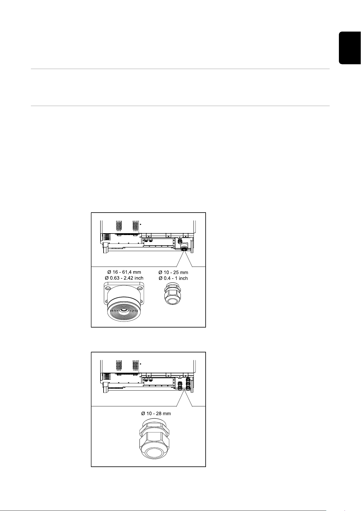
Cable gland "Multicore" version
The following cable outer diameters
are compatible with the larger bushing:
16 - 27.8 - 36.2 - 44.6 - 53 - 61.4 mm
EN
Cable gland "Singlecore" version
For the small bushing (M32 PG gland),
earth cables of 10 - 25 mm can be fed
through.
5 M40 bushings
39

Cable gland "AC Daisy Chain" version
10 M32 bushings
Connecting aluminium cables
Permitted cables For the pre-combined variant, the temperature resistance of the AC cables must
Aluminium cables can be connected to the mains connections.
NOTE!
When connecting aluminium cables:
Observe national and international guidelines regarding the connection of
▶
aluminium cables
To protect the aluminium strands from oxidation, grease them with a suitable
▶
grease.
Follow the instructions of the cable manufacturer
▶
be at least 90 C.
If cables are used that do not meet this temperature requirement, pass the protective hose (item number: 4,251,050) over the phases (L1 / L2 / L3) and neutral
conductor (N). The earthing PE does not have to be protected with a protective
hose.
With the AC Daisy Chain option, all phases and neutral conductors must be protected with the protective hose. Thus, two sets of protective hoses are required
for the AC Daisy Chain option.
40
Grid connections
Select sufficiently high cable cross sections depending on the power category
and connection option!
Power category Connection option Cable cross section
Tauro 50-3
Tauro Eco 50-3
Singlecore/Multicore
Optional AC disconnector
Daisy Chain (without AC discon-
nector)
35–240 mm2 *
35–240 mm2 *
35–240 mm2 *

Grid connections
Maximum alternating current
fuse protection
Select sufficiently high cable cross sections depending on the power category
and connection option!
Power category Connection option Cable cross section
Singlecore/Multicore
Tauro Eco 99-3
Tauro Eco 100-3
* The cable cross-section of the neutral conductor can be reduced to 25 mm² if
no local directives or standards require otherwise.
NOTE!
There is no general requirement to use a residual current device.
If a residual current device (RCD) is nevertheless used, a type B with a tripping
current of at least 1000 mA must be used.
NOTE!
Optional AC disconnector
Daisy Chain (without AC discon-
nector)
70–240 mm2 *
70–240 mm2 *
70–240 mm2 *
EN
The inverter can be used with an automatic circuit breaker of a maximum of
355 A.
Recommended output overcurrent protection [A]
for 50 kW output power
Recommended output overcurrent protection [A]
for 100 kW output power
(example: Daisy Chaining)
Recommended output overcurrent protection [A]
for 150 kW output power
(example: Daisy Chaining)
Tauro Eco 99-3-P
Tauro 50-3-D / 50-3-P
Tauro Eco 50-3-D / 50-3-P
80 80 - - - -
160 160 160 160 160 160
250 250 250 250 250 250
Tauro Eco 99-3-D
Tauro Eco 100-3-P
Tauro Eco 100-3-D
Recommended output overcurrent protection [A]
for 200 kW output power
(example: Daisy Chaining)
355 355 355 355 355 355
41

Changing the
clamping area
for V-type terminal
The clamping range of the V-type terminal is 35 - 150 mm² when delivered. The
clamping range can be changed to 185 - 240 mm² by a simple modification of the
V-type terminal.
Additional PE introduction for
earthing
An optional hole can be made on the right side of the housing at the bottom for
an additional PE introduction.
CAUTION!
Danger from faulty or incorrect holes.
This may lead to injuries to the eyes and hands as a result of flying debris and
sharp edges, as well as damage to the inverter.
When drilling, wear suitable protective goggles.
▶
Only use a step drill when drilling.
▶
Ensure that nothing is damaged inside the device (for example connection
▶
block).
Adapt the diameter of the hole to match the corresponding connection.
▶
Deburr the holes using a suitable tool.
▶
Remove the drilling residues from the inverter.
▶
1
42

2
Insert the screw connection in the hole
and secure to the torque specified by
the manufacturer.
The opening must be sealed in accordance with the protection class of the
inverter!
EN
Safety
WARNING!
Danger due to grid voltage and DC voltage from solar modules.
An electric shock can be fatal.
Ensure that both the AC side and the DC side of the inverter are de-ener-
▶
gised before carrying out any connection work.
Only an authorised electrical engineer is permitted to connect this equip-
▶
ment to the public grid.
CAUTION!
Risk of damage to the inverter as the result of incorrectly tightened cable connections.
Incorrectly tightened cable connections can cause heat damage to the inverter
that may result in a fire.
When connecting AC and DC cables, ensure that all the cables are tightened
▶
to the inverter terminals with the specified torque.
IMPORTANT! For PE connection, the requirements defined under "Safety rules"
for a safe connection of the PE conductor must also be observed.
Opening the inverter
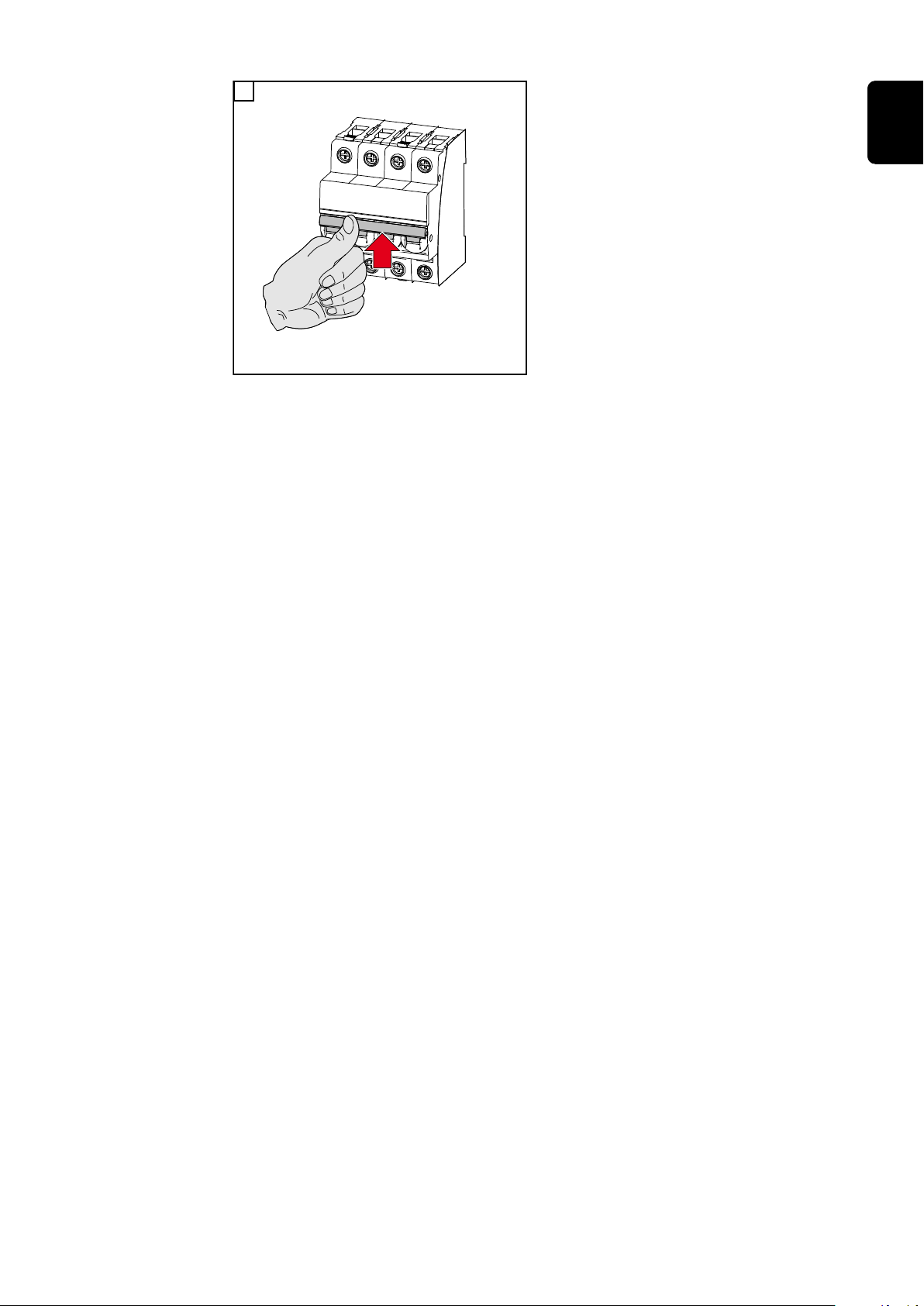
1 2
43

Switching off the
AC disconnector
option
1
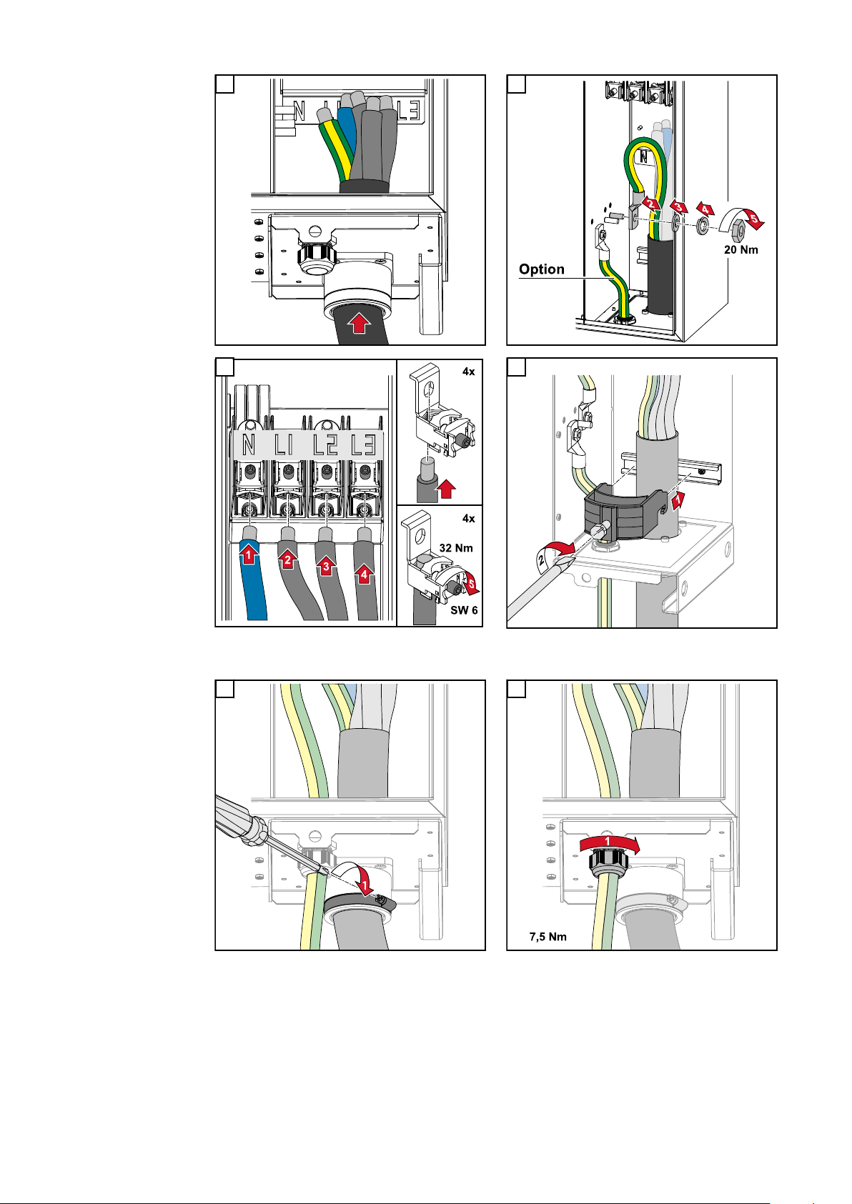
Connecting the
inverter to the
public grid Singlecore
Ensure that the phases are connected in the right order: PE, N, L1, L2 and L3.
1 2
3 4
44

5 6
7
EN
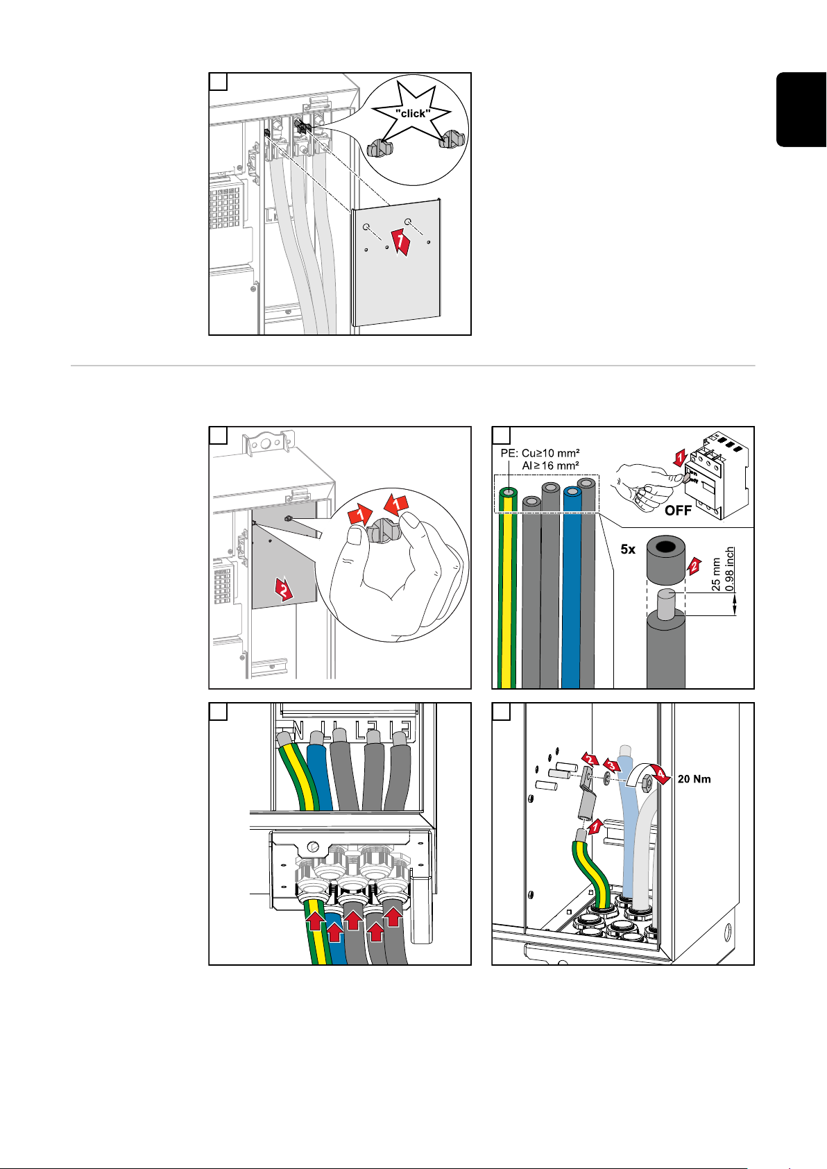
Connecting the
inverter to the
public grid - Multicore
When connecting, ensure that the phases are in the correct order: PE, N, L1, L2
and L3.
1 2
45
3 4
5
7 8
6
Secure to the torque specified by the manufacturer of the strain-relief device. The strain-relief
device is not part of the scope of supply.
46
Secure to the torque specified by the manufacturer
9
EN
Connecting the
inverter to the
public grid Daisy Chain
Ensure that the phases are connected in the right order: PE, N, L1, L2 and L3.
1 2
3 4
47

5 6
7 8
Connecting
cables with a
cable lug
9 10
Alternatively, a cable with a cable lug can be connected to the M12 threaded
bolts on the grid connections in order to connect the cables to the V-type terminals.
48

EN
49

Connecting the PV cable to the inverter
Safety
WARNING!
Danger due to grid voltage and DC voltage from solar modules that are exposed
to light.
An electric shock can be fatal.
Prior to any connection work, disconnect the inverter on the AC side and the
▶
DC side.
Only an authorised electrical technician is permitted to connect this equip-
▶
ment to the public grid.
WARNING!
Danger of electric shock due to incorrectly connected terminals / PV plug connectors.
An electric shock can be fatal.
When connecting version D ("direct string"), ensure that every pole of a
▶
string is fed across the same PV input, e.g.:
'+ pole string 1' at input PV 1.1+ and '- pole string 1' at input PV 1.1-
WARNING!
Danger from DC voltage. Even when the DC disconnectors are switched off, the
fuse boards (100-3-D / 99-3-D) / fuse board (50-3-D) and everything before the
DC disconnectors are live.
An electric shock can be fatal.
Prior to any connection work, disconnect the inverter on the AC side and the
▶
DC side.
CAUTION!
Risk of damage to the inverter as the result of incorrectly tightened terminals.
Incorrectly tightened terminals can cause heat damage to the inverter that may
result in a fire.
When connecting AC and DC cables, ensure that all the terminals are
▶
tightened to the specified torque.
CAUTION!
Risk of damage to the inverter as the result of incorrectly tightened terminals.
Incorrectly tightened terminals can cause heat damage to the inverter that may
result in a fire.
When connecting AC and DC cables, ensure that all the terminals are
▶
tightened to the specified torque.
50

CAUTION!
General comments regarding
PV modules
Risk of damage to the inverter due to PV modules that are not connected with
the correct polarity.
PV modules that are not connected with the correct polarity can cause thermal
damage to the inverter.
Measure the DC cables from the PV modules and connect them to the in-
▶
verter with the correct polarity.
CAUTION!
Risk of damage to the inverter by exceeding the maximum input current per
string.
Exceeding the maximum input current per string can cause damage to the inverter.
Observe the maximum input current per string for the inverter according to
▶
the technical data.
The maximum input current must not be exceeded even when using Y or T
▶
connectors.
To enable suitable PV modules to be chosen and to use the inverter as efficiently
as possible, it is important to bear the following points in mind:
If insolation is constant and the temperature is falling, the open-circuit
-
voltage of the PV modules will increase. The open-circuit voltage must not
exceed the maximum permissible system voltage. If the open-circuit voltage
exceeds the specified values, the inverter will be destroyed and all warranty
claims will be forfeited.
The temperature coefficients on the data sheet of the PV modules must be
-
observed.
Exact values for sizing the PV modules can be obtained using suitable calcu-
-
lation tools, such as the Fronius Solar.creator.
EN
IMPORTANT!
Before connecting up the PV modules, check that the voltage for the PV modules specified by the manufacturer corresponds to the actual measured voltage.
IMPORTANT!
The PV modules connected to the inverter must comply with the IEC
61730 Class A standard.
IMPORTANT!
Solar module strings must not be
earthed.
Permitted cables The temperature resistance of the DC cables must be at least 90 °C.
51

DC connections
Select sufficiently high cable cross sections depending on the device type!
Power category Device type Cable cross section
Tauro 50-3 / Eco 50-3 /
Eco 99-3 / Eco 100-3
pre-combined
direct
25 - 95 mm
2,5 - 10 mm² (see
data sheet for con-
nector)
2
DC fuse protection - pre-combined
CAUTION!
Risk of damage to the inverter as the result of incorrectly fused PV lines.
PV lines for the "pre-combined" model that are not fused can cause damage to
the inverter.
PV lines must be fused in a combiner box before the inverter ("pre-com-
▶
bined" version).
52

Example of
PV 1.1 PV 1.2 PV 1.n
* SPD
PV 1
breaker
* DC
PV 2.1 PV 2.2 PV 2.n
* SPD
PV 2
breaker
* DC
PV 1 PV 2
... ...
Combiner Box
GAK
-F1.1.1
-F1.1.2
-F1.2.1
-F1.2.2
-F1.n.1
-F1.n.2
-F2.1.1
-F2.1.2
-F2.2.1
-F2.2.2
-F2.n.1
-F2.n.2
* Fuses
* Fuses
Fronius Tauro
Eco 50-3-P /
99-3-P / 100-3-P
combiner box
EN
* DC fuse optional depending on national standard / DC breaker optional / DC SPD optional
53

Example Fronius
PV 1.1 PV 1.2 PV 1.n
* SPD
PV 1
breaker
* DC
PV 2.1 PV 2.2 PV 2.n
* SPD
PV 2
breaker
* DC
PV 3.1 PV 3.2 PV 3.n
* SPD
PV 3
breaker
* DC
PV 1 PV 2 PV 3
... ... ...
Combiner Box
GAK
-F1.1.1
-F1.1.2
-F1.2.1
-F1.2.2
-F1.n.1
-F1.n.2
-F2.1.1
-F2.1.2
-F2.2.1
-F2.2.2
-F2.n.1
-F2.n.2
-F3.1.1
-F3.1.2
-F3.2.1
-F3.2.2
-F3.n.1
-F3.n.2
* Fuses
* Fuses
* Fuses
Tauro 50-3-P
combiner box
Distribution of
the solar module
strings for the
direct version
* DC fuse optional depending on national standard / DC breaker optional / DC SPD optional
Divide the existing solar module strings evenly between the PV inputs (PV1 /
PV2 / PV3) of the inverter.
Start with the odd inputs first and only then fill up the even inputs to divide the
power as evenly as possible and extend the service life of the fuses, e.g.: (1.1, 2.1,
3.1, 1.3, 2.3...)
54

Connecting PV
cables - MC4
connector
1
Connect the PV cables from the solar
modules to the MC4 connectors as la-
EN
belled
Unused MC4 connectors on the inverter must be covered with the cover
plates supplied with the inverter.
MC4 connector
cover
To protect the MC4 connectors, a cover plate can be mounted on the inverter.
The cover plate can be ordered as an optional accessory together with the floor
racks.
55

Connecting PV
cables - Precombined
Solar module strings that are combined in a DC combiner box, must, according
to the applicable national regulations, be fused per string in the DC combiner
box!
Before working in the connection area of the inverter, the DC
voltage must be switched off. This can also be done in the DC
combiner box.
1 2
3 4
56

5 6
7 8
EN
Connecting
cables with a
cable lug
Alternatively, a cable with a cable lug can be connected to the M12 threaded
bolts on the grid connections in order to connect the cables to the V-type terminals.
57

Replacing the
string fuses
CAUTION!
Danger due to faulty fuses.
This can lead to fires.
Only replace faulty fuses with new ones of the same rating.
▶
Do not replace faulty fuses with bolts.
▶
CAUTION!
Danger due to incorrectly dimensioned string fuses
Incorrectly dimensioned string fuses can cause damage to the inverter for these
connected components.
The following string fuses should be used for the -D (direct) version of the Fronius Tauro:
Max. 10 A per string → use of 15 A gPV fuse 1000 V possible (Fronius item
▶
number: 41,0007,0230 - fuse 15 1000 F PV 15A)
Max. 14.5 A per string → use of 20 A gPV fuse 1000V required (Fronius item
▶
number: 41,0007,0233 - fuse-HL 20A 1KV fast)
Max. 22 A per string → use of 30 A gPV fuse 1000V required (Fronius item
▶
number: 41,0007,0241 - fuse-HL 30A 1KV fast)
Replacing fuses:
Fronius Tauro 50-3-D string 1.1 - 3.7 /
Fronius Tauro 50-3-D (30A fuses) string 1.1 - 3.5 /
Fronius Tauro Eco 50-3-D string 1.1 - 2.7 /
Tauro Eco 50-3-D (30A fuses) string 1.1 - 2.5 /
Fronius Tauro Eco 99 / 100-3-D string 1.1 - 2.7 /
Fronius Tauro Eco 99 / 100-3-D (30A fuses) string 1.1 - 3.5
Check values! Only replace faulty fuses with new ones of the same rating.
1
58

Replacing fuses:
Fronius Tauro Eco 99 / 100-3-D string 3.1 - 3.8
Check values! Only replace faulty fuses with new ones of the same rating.
1 2
3 4
EN
5
59
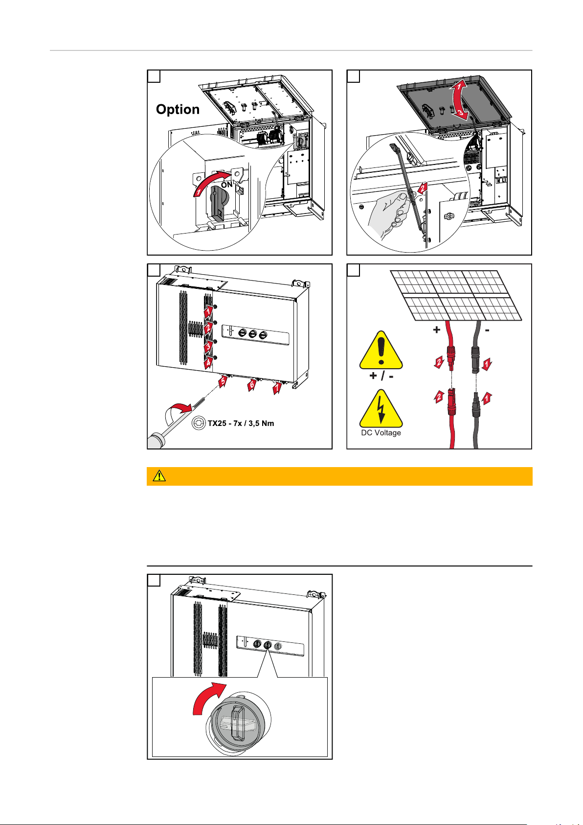
Closing and
OFF
ON
2
2-3x
switching on the
inverter
1 2
3 4
WARNING!
Danger due to DC disconnectors that are not switched on properly
This can result in serious injury and damage to property.
Turn all existing DC disconnectors to the ON position before turning on the
▶
AC connection.
The DC disconnectors may only ever be actuated simultaneously (one imme-
▶
diately after the other).
5
The WLAN access point can be opened
with the optical sensor, see chapter
Button functions and LED status indicator on page 26
60
AC~
ON
1
6
EN
61

Connecting the data communication cable
Modbus participants
The inputs M0 and M1 can be freely selected. A maximum of 4 Modbus participants can be connected to the Modbus terminal on inputs M0 and M1..
IMPORTANT!
If the function „Inverter control via Modbus“ is activated in the menu area
„Communication“ → „Modbus“, no Modbus participants are possible. It is not
possible to send and receive data at the same time.
Permitted cables
for the data
Cables with the following design can be connected to the terminals of the inverter:
communication
area
Copper: round, solid
-
Copper: round, fine-stranded
-
WSD connections with push-in terminal
Distance
max.
Stripping
length
Solid
Fine-stran-
ded
Fine-stran-
ded with fer-
rules with
collar
Fine-stran-
ded with fer-
rules
without col-
lar
Cable re-
commenda-
tion
100 m
10 mm
0.14 - 1.5
2
mm
Modbus connections with push-in terminal
Distance
max.
300 m
Stripping
length
10 mm
Solid
0.14 - 1.5
2
mm
Fine-stran-
IO connections with push-in terminal
Distance
max.
30 m
Stripping
length
10 mm
Solid
0.14 - 1.5
2
mm
Fine-stran-
0.14 - 1.5
2
mm
ded
0.14 - 1.5
2
mm
ded
0.14 - 1.5
2
mm
0.14 - 1 mm
Fine-stran-
ded with fer-
rules with
collar
0.14 - 1 mm
Fine-stran-
ded with fer-
rules with
collar
0.14 - 1 mm
0.14 - 1.5
2
mm
Fine-stran-
ded with fer-
rules
without col-
0.14 - 1.5
2
mm
Fine-stran-
ded with fer-
rules
without col-
0.14 - 1.5
2
mm
lar
lar
2
UTP
Cable re-
commenda-
tion
min. CAT 5
min. CAT 5
2
STP
Cable re-
commenda-
tion
Single con-
2
ductor pos-
sible
62

LAN connections
Fronius recommends at least CAT 5 STP (Shielded Twisted Pair) cables and a maximum distance of
100 m.
Multiple inverters in one net-
The network cabling of the inverters must be in a star arrangement. Observe the
maximum lengths and requirements for the cable!
work
EN
Routing data
communication
cables
To use the connection to Fronius Solar.web or Modbus TCP, each Tauro must be
connected directly to the network via LAN.
IMPORTANT! If data communication cables are wired into the inverter, observe
the following points:
Depending on the number and cross section of the wired data communica-
-
tion cables, remove the corresponding blanking plugs from the sealing insert
and insert the data communication cables.
Make sure that you insert the corresponding blanking plugs into any free
-
openings on the sealing insert.
Note! Should the blanking plugs be missing or improperly fitted, then protection
class IP65 cannot be guaranteed.
1
Undo the strain-relief device cap nut
and push out the sealing ring and the
blanking plug from the inside of the
device.
63
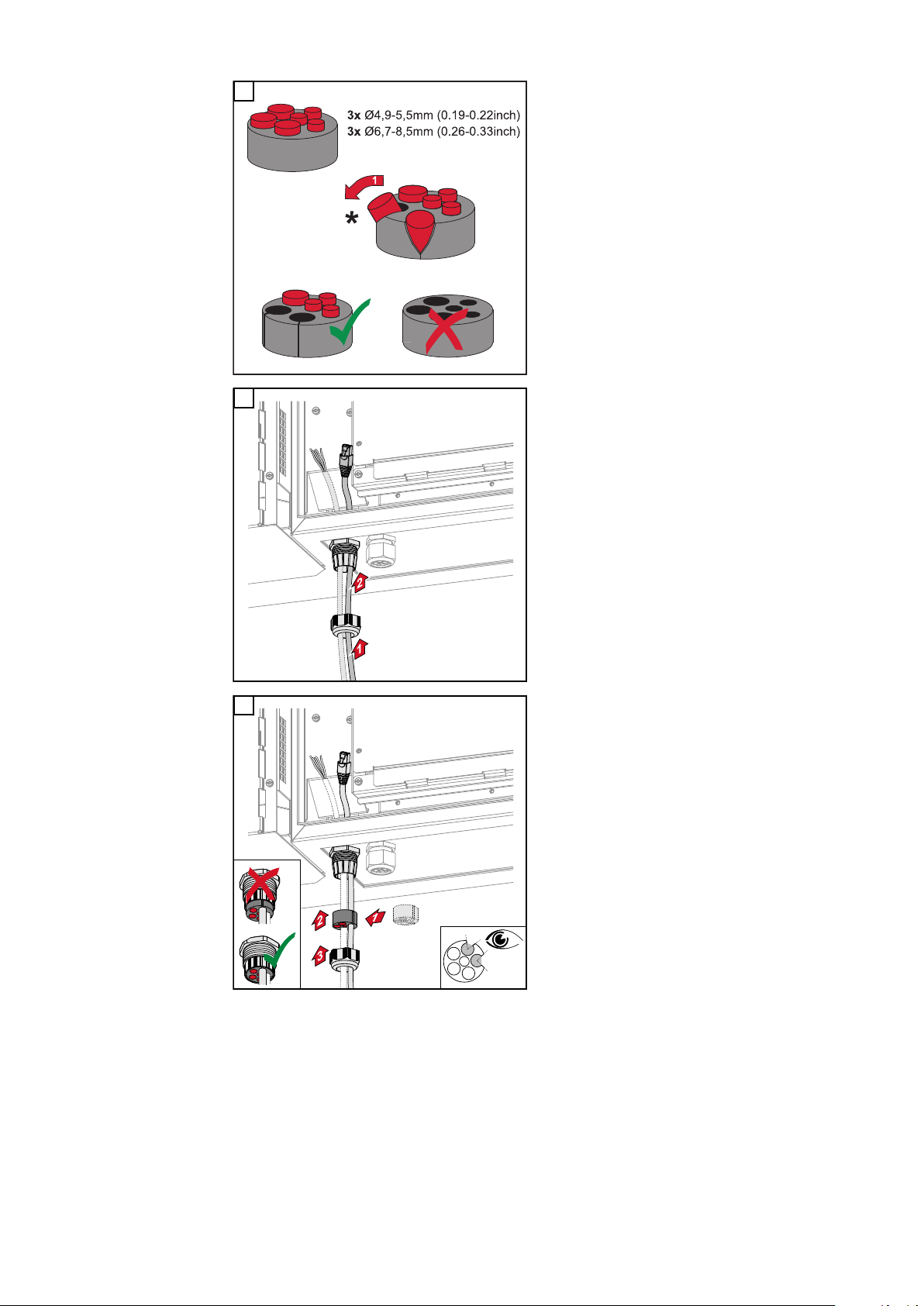
2
Open up the sealing ring at the location where the blanking plug is to be
removed.
* Liberate the blanking plug by moving
it sideways.
3
Guide the data cables first through the
strain-relief device cap nut and then
through the housing opening.
4
Insert the sealing ring between the cap
nut and the housing opening. Press the
data cables into the seal's cable guide.
Then press in the seal until it reaches
the underside of the strain-relief
device.
64
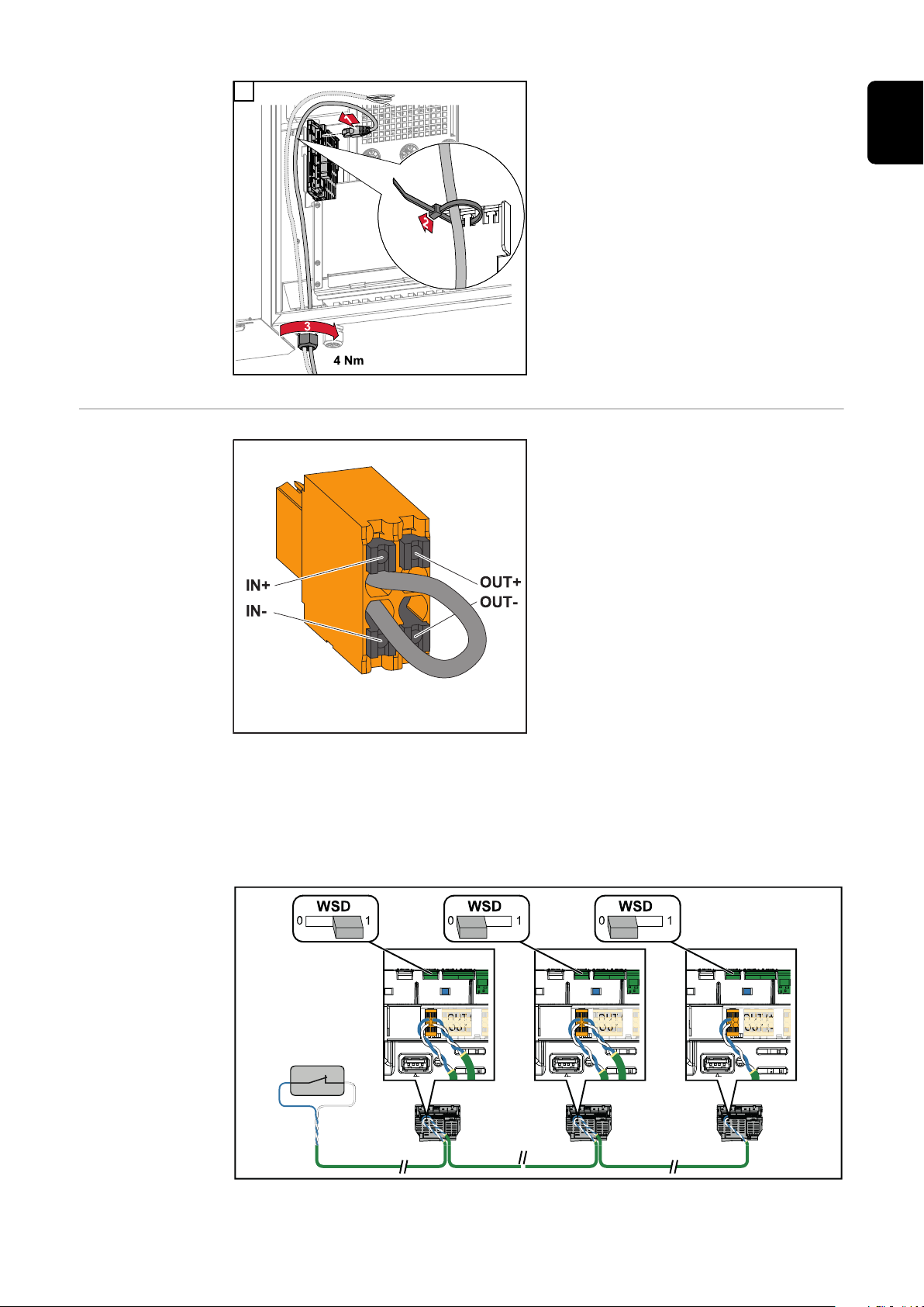
5
IN (+)
IN (-)
OUT (+)
OUT (-)
IN (+)
IN (-)
OUT (+)
OUT (-)
IN (+)
IN (-)
OUT (+)
OUT (-)
CAT 5/6/7
*
Connect the data cables to the data
communication area using a movement
loop, and fasten the cap nut with min.
EN
2.5 to max. 4 Nm.
WSD (wired
shutdown)
IMPORTANT!
The push-in WSD terminal in the inverter's connection area is delivered
with a bypass ex works as standard.
The bypass must be removed when installing a trigger device or a WSD
chain.
The WSD switch of the first inverter with connected trigger device in the WSD
chain must be in position 1 (primary device). The WSD switch of all other inverters should be in the 0 (secondary device) position.
Max. distance between two devices: 100 m
Max. number of devices: 28
65

* Floating contact of the trigger device (e.g. central grid and system protection).
If several floating contacts are used in a WSD chain, they must be connected in
series.
66

Using for the first time
1 2
open access point
Setup your PV system in a few minutes.
START INSTALLATION
LOGIN
Log in with your Fronius credentials (email adress
& password) in order to get the most out of the
PV System. Installing a new product does not
require a Login.
Imprint & Contact Terms & ConditionsData Privacy
Fronius Solar.start
EN
Starting the inverter for the
first time
Fronius system
monitoring (Pilot) display
When starting the inverter for the first time, various setup settings must be configured.
If the setup process is cancelled before the process is complete, any data that
has been input up to this point is lost and the start screen with the installation
wizard is shown again. If the process is interrupted, such as in the event of a
power outage, the data is saved. Commissioning may be continued from the point
at which the process was interrupted once the power supply has been restored. If
the setup was interrupted, the inverter feeds energy into the grid at maximum
500 W and the operating status LED flashes yellow.
The country setup can only be set when starting the inverter for the first time. If
the country setup needs to be changed at a later date, please contact your installer / Technical Support team.
To simplify the display, the vertical installation position of the Pilot pc board
(LED display) is shown horizontally below.
Installation with
the app
The "Fronius Solar.start" app is required for this installation method. Depending
on the end device with which the installation will be carried out, download the
app for the respective platform.
Start the installation in the app.
1
Select the product to which the connection should be established.
2
3
Open the access point by touching the sensor once → Communication LED:
flashes blue.
Follow and complete the installation wizard in the individual sections.
4
Add system components in Solar.web and start up the PV system.
5
67

The network wizard and the product setup can be carried out independently of
open access point
1
FRONIUS_PILOTxxx
Secured
Password:
12345678
2
192.168.250.181
169.254.0.180
21
open access point
each other. A network connection is required for the Solar.web installation wizard.
Installation using the web
browser
WLAN:
1
Open the access point by touching the sensor once → Communication LED:
flashes blue.
Establish the connection to the inverter in the network settings (the inverter
2
is displayed with the name "FRONIUS_PILOT" and the serial number of the
device).
Password: enter 12345678 and confirm.
3
IMPORTANT!
To enter the password on a Windows 10 operating system, the link "Connect
using a security key instead" must first be activated to establish a connection
with the password: 12345678.
In the browser address bar, enter and confirm the IP address
4
192.168.250.181. The installation wizard is opened.
Follow the installation wizard in the individual sections and complete the in-
5
stallation.
Add system components in Solar.web and start up the PV system.
6
The network wizard and the product setup can be carried out independently of
each other. A network connection is required for the Solar.web installation wizard.
Ethernet:
Establish a connection to the inverter (LAN1) with a network cable (CAT5
1
STP or higher).
2
Open the access point by touching the sensor once → Communication LED:
flashes blue.
In the browser address bar, enter and confirm IP address 169.254.0.180. The
3
installation wizard is opened.
Follow the installation wizard in the individual sections and complete the in-
4
stallation.
Add system components in Solar.web and start up the PV system.
5
68

The network wizard and the product setup can be carried out independently of
each other. A network connection is required for the Solar.web installation wizard.
EN
69

Switching off current supply and restarting the
inverter
De-energising
the inverter and
switching it on
again
Turn off the automatic circuit
1
1.
breaker.
Turn the DC disconnector to the
2.
"Off" switch position.
To start up the inverter again, follow
the steps listed above in reverse order.
70

Settings - user interface of the in-
verter
71

72

User settings
EN
User login
Selecting the
language
Open the user interface of the inverter in your browser.
1
In the "Login" menu, log in using your user name and password, or go to the
2
"User" menu and click on the "User login" button and then log in with your
user name and password.
IMPORTANT!
Depending on the user's authorization, settings can be executed in the individual
menus.
In the “User” menu, click on the “Language” button and select the desired
1
language.
73

Device configuration
Components Select "Add component+" to add all available components to the system.
PV generator
Activate the particular PV generator and enter the connected PV power in the
associated field.
Primary meter
To ensure smooth operation in conjunction with other energy producers, it is important to install the Fronius Smart Meter at the feed-in point. The inverter and
other producers must be connected to the public grid via the Fronius Smart
Meter.
This setting also affects how the inverter behaves overnight. If the function is deactivated, the inverter switches to standby mode as soon as there is no more PV
power available. The message "Power low" is displayed. The inverter starts again
as soon as sufficient PV power is available.
After connecting the meter, the position must be configured.
Several Fronius Smart Meters can be installed in the system. A different address
needs to be set for each Smart Meter.
The Watt value on the generator meter is the sum of all generator meters. The
Watt value on the consumption meter is the value of all consumption meters.
Functions and
IOs
Ohmpilot
All Ohmpilots available in the system are displayed. Select the desired Ohmpilot
and add it to the system via “Add”.
Load management
Up to four pins can be selected here for load management. Other load management settings are available in the Load Management menu item.
Default: Pin 1
OFF - Demand Response Mode (DRM)
The pins for control via DRM can be set here:
De-
fault
Mode Description Information
DRM0 Inverter disconnects itself
from the grid
REF GEN RG0
COM LOAD CL0
Open grid relay
pin
74
DRM0 occurs if there is an interruption or short circuit on
the REF GEN or COM LOAD
leads. Or if the combinations
DRM1 - DRM8 are invalid.

IMPORTANT!
If the Demand Response Mode (DRM) function is enabled and no DRM control is
connected, the inverter switches to Standby mode.
EN
"PSC editor AUS - Demand
Response Modes
(DRM)"
Demand Response Modes
(DRM)
Inverter "Enforce Standby"
A value for the apparent power consumption and apparent power output can be
entered here for the Australia country setup.
Here you can enter a value for the apparent power input and the apparent power
output for the Australia country setup.
When the function is activated, the feed-in mode of the inverter is interrupted.
This enables a powerless shutdown of the inverter and protects its components.
When the inverter is restarted, the standby function is automatically deactivated.
"PV 1" and "PV 2"
Parameter Value range Description
"Mode" Off The MPP tracker is deactivated.
Auto The inverter uses the voltage at which the
max. possible power of the MPP tracker is
possible.
Fix The MPP tracker uses the voltage defined
in the "UDC fix".
"UDC fix" 80 ‑ 530 V The inverter uses the fixed preset voltage
used at the MPP tracker.
"Dynamic Peak
Manager"
"Ripple Control"
Ripple control signals are signals sent out by the energy company to switch controllable loads on and off. Depending on the installation situation, ripple control
signals may be attenuated or amplified by the inverter. The settings below can be
used to counteract this if necessary.
Parameter Value range Description
"Reduction of
Influence"
"Frequency of
Ripple Control
Signal"
Off The function is deactivated.
On The entire solar module string is checked
for optimisation potential and determines
the best possible voltage for feed-in mode.
Off The function is deactivated.
On The function is activated.
100 ‑ 3000 Hz The frequency specified by the energy
company must be entered here.
"Grid Inductance"
0.00001 ‑ 0.00
5 H
The value measured at the feed-in point
must be entered here.
75

"Measures against RCD/RCMU false trips"
(when using a 30 mA residual current circuit breaker)
Parameter Value range Description
"Inverter shutdown before
30 mA RCD
trips"
"Iso Warning"
Parameter Value range Description
"Iso Warning" Off The isolation warning is deactivated.
"Iso Alternative
Mode"
"Isolation
Warning
Threshold"
0 No measures to prevent false tripping.
1 The inverter switches off at 15 mA before
the residual current circuit breaker trips.
On The isolation warning is activated.
A warning is issued in the event of an isolation fault.
Accurate Isolation monitoring is performed with the
highest accuracy and the measured insulation resistance is displayed on the user interface of the inverter.
Fast Isolation monitoring is performed with
lower accuracy, which shortens the duration of the isolation measurement, and the
isolation value is not displayed on the user
interface of the inverter.
10 ‑
10,000 kΩ
If this threshold is undershot, status code
1083 is displayed on the user interface of
the inverter.
76

System
General General settings
In the "System name" input field, enter the name of the system (max. 30
1
characters).
"Synchronize time automatically" enabled → select "Area time zone" and
2
"Location time zone". The date and time are applied from the time zone
entered.
"Synchronize time automatically" disabled → enter or select "Date", "Time",
2
"Area time zone" and "Location time zone".
Click on the "Save" button.
3
Update All available updates are made available on the product page and in the "Down-
load search" area under www.fronius.com .
Firmware update
Drag the firmware file into the "Drag&Drop file here" field or select it using
1
"Select file".
EN
The update will start.
Setup wizard The guided setup wizard can be accessed here.
Restoring the
factory settings
Event log Current events
All settings
All configuration data is reset with the exception of the country setup. Changes
to the country setup may only be carried out by authorized personnel.
All settings with no network
All configuration data is reset with the exception of the country setup and the
network settings. Changes to the country setup may only be carried out by authorized personnel.
All current events of the connected system components are shown here.
IMPORTANT!
Depending on the type of event, these must be confirmed via the "tick" button in
order to be processed further.
Archived
All events of the connected system components that no longer exist are shown
here.
Information This menu displays all system information and the current settings.
77

Save as PDF
Click on the "Save as PDF" button.
1
Individually select information with the "tick" next to the information or tick
2
to "Select all".
Enter the file name in the input field and click on the "Save" button.
3
The PDF is created and displayed.
Licence manager The licence file contains the performance data and the scope of functions of the
inverter. When replacing the inverter, power stage set or data communication
area, the licence file must also be replaced.
Licensing - online (recommended):
An Internet connection and completed configuration on Solar.web is required.
Complete the installation work (see chapter Using for the first time on page
1
67).
Connect to the user interface of the inverter.
2
Enter the serial number and verification code (VCode) of the defective and
3
replacement unit. The serial number and the VCode can be found on the rating plate of the inverter (see chapter Warning notices and rating plate on the
device on page 14).
Click on the "Start online licensing" button.
4
Skip the Terms of use and Network settings menu items by clicking on
5
"Next".
The licence activation starts.
Licensing - offline:
There must be no Internet connection for this. When licensing offline with an established internet connection, the licence file is automatically uploaded to the
inverter. Therefore, when uploading the licence file, the following error occurs:
"The licence has already been installed and the wizard can be closed".
Complete the installation work (see chapter Using for the first time on page
1
67).
Connect to the user interface of the inverter.
2
Enter the serial number and verification code (VCode) of the defective and
3
replacement unit. The serial number and the VCode can be found on the rating plate of the inverter (see chapter Warning notices and rating plate on the
device on page 14).
Click on the "Start offline licensing" button.
4
Download the service file onto the end device by clicking on the "Download
5
service file" button.
Open the website licensemanager.solarweb.com and log in with your user
6
name and password.
Drag or upload the service file into the "Drop service file here or click to up-
7
load” field.
Download the newly generated licence file onto the end device using the
8
"Download licence file" button.
Go to the user interface of the inverter and drag the licence file into the
9
"Drag&Drop licence file here" field, or select it via "Select licence file".
78
The licence activation starts.

Support Activate support user
Click the "Activate support user" button.
1
The support user is activated.
IMPORTANT!
The support user only allows Fronius Technical Support to implement settings on
the inverter via a secure connection. The button "End support user access" deactivates the access.
Create support info (for Fronius Support team)
Click on the "Create support info" button.
1
The sdp.cry file is downloaded automatically. To download manually, click on
2
the "Download Support-Info" button.
The sdp.cry file is saved in the downloads.
Enable remote maintenance
Click on the "Enable remote maintenance" button.
1
Remote maintenance access for the Fronius Support team is enabled.
IMPORTANT!
Remote maintenance access gives Fronius Technical Support exclusive access to
the inverter via a secure connection. Diagnostic data is transmitted here that can
be used for troubleshooting purposes. Only enable remote maintenance access
following a request from the Fronius Support team.
EN
79

Communication
Network Server addresses for data transfer
If a firewall is used for outgoing connections, the following protocols, server addresses and ports must be allowed for successful data transfer:
Tcp fronius-se-iot.azure-devices.net:8883
-
Tcp fronius-se-iot-telemetry.azure-devices.net:8883
-
Tcp fronius-se-iot-telemetry.azure-devices.net:443
-
Udp sera-gen24.fronius.com:1194 (213.33.117.120:1194)
-
Tcp froniusseiot.blob.core.windows.net:443
-
Tcp provisioning.solarweb.com:443
-
Tcp cure-se.fronius.com:443
-
When using FRITZ!Box products, the Internet access must be configured to be
unlimited and unrestricted.
LAN:
Enter host name.
1
Select connection type "automatic" or "static".
2
For connection type "static" - enter IP address, subnet mask, DNS and gate-
3
way.
Click on the "Connect" button.
4
The connection is established.
WLAN:
Establishing a connection via WPS:
Click the "Enable" button.
1
Activate WPS on the WLAN router (see documentation provided with the
2
WLAN router).
The connection is established automatically.
Select and connect WLAN network:
The networks found are shown in the list. Clicking on the refresh button will
carry out a second search of the available WLAN networks. The "Find network"
input field can be used to further restrict the selection list.
Select network from the list.
1
Select connection type "automatic" or "static".
2
For connection type "automatic" - enter WLAN password and host name.
3
For connection type "static" - enter IP address, subnet mask, DNS and gate-
4
way.
Click on the "Connect" button.
5
80

The connection is established.
Access point:
The inverter serves as an access point. A PC or smart device connects directly
with the inverter. It is not possible to connect to the internet. The "Network
name (SSID)" and "Network key (PSK)" can be assigned in this menu.
It is possible to operate a connection via WLAN and via access point simultaneously.
Modbus To use the Modbus TCP or the connection to Fronius Solar.web, each Tauro must
be connected directly to the network via LAN.
Modbus RTU interface 0 / 1
If one of the two Modbus RTU interfaces is set to Slave, the following input fields
are available:
“Baud rate”
The baud rate influences the transmission speed between the individual components connected in the system. When selecting the baud rate, ensure that it is the
same at both the sending and receiving end.
EN
“Parity”
The parity bit can be used to check the parity. It detects transmission errors. A
parity bit can safeguard a specific number of bits. The value (0 or 1) of the parity
bit must be calculated by the sender and is checked by the recipient using the
same calculation. The parity bit can be calculated for even and odd parity.
"SunSpec Model Type"
Depending on the SunSpec model, there are two different settings.
float: SunSpec Inverter Model 111, 112, 113 or 211, 212, 213.
int + SF: SunSpec Inverter Model 101, 102, 103 or 201, 202, 203.
"Meter address"
"Inverter address"
Slave as Modbus TCP
If the function "Slave as Modbus TCP" is activated, the following input fields are
available:
"Modbus port"
Number of the TCP port that is to be used for Modbus communication.
"SunSpec Model Type"
Depending on the SunSpec model, there are two different settings.
float: SunSpec Inverter Model 111, 112, 113 or 211, 212, 213.
int + SF: SunSpec Inverter Model 101, 102, 103 or 201, 202, 203.
"Meter address"
81

Inverter control via Modbus
If this option is activated, the inverter is controlled via Modbus.
Inverter control includes the following functions:
On/Off
-
Power reduction
-
Specification of a constant power factor (cos phi)
-
Specification of a constant reactive power value
-
Remote control
Remote control and profiles
The grid operator/energy supplier can influence the output power of the inverter
by means of remote control. The prerequisite for this is for the inverter to have
an active internet connection.
Parameter Value range Description
Remote control Off Remote control of the inverter is deactiv-
ated.
On Remote control of the inverter is activ-
ated.
Allow remote
control for regulatory purposes (technician)
Allow remote
control for virtual power
plants (customer)
Deactivated/
Activated
Deactivated/
Activated
The function Allow remote control for
regulatory purposes may be mandatory
for proper operation of the system. *)
If the Allow remote control for regulatory
purposes function is enabled (technician
access required), the Allow remote con-
trol for virtual power plants function is
automatically enabled and cannot be disabled. *)
Fronius Solar
API
*) Cloud Control
A virtual power plant is an interconnection of several power plant operators to
form a network. This network can be controlled via the cloud over the internet.
The inverter must have an active internet connection for this. System data is
transmitted.
The Fronius Solar API is an Ethernet-based, open JSON interface. When enabled, IOT devices on the local network can access inverter information without
authentication. For security reasons, the interface is deactivated at the factory
and should not be activated if it is not required for a third-party application (e.g.
EV charger, smart home solutions, etc.).
For monitoring, Fronius recommends using Fronius Solar.web instead, which
provides secure access to inverter status and production information.
When performing a firmware update to version 1.14.x, the setting of the Fronius
Solar API is adopted.
82

Safety and grid requirements
Country setup The "Country Setup" menu area is intended exclusively for installers/service
technicians from authorised specialist companies. The access code must be requested from the national/international Fronius point of contact using an application form.
CAUTION!
Risk due to unauthorised access.
Incorrectly set parameters can negatively influence the public grid and/or the inverter feeding energy into the grid, and lead to a loss of conformity with the
standard.
The parameters may only be adjusted by installers/service technicians from
▶
authorised specialist companies.
Do not give the access code to third parties and/or unauthorised persons.
▶
WARNING!
Danger due to unauthorised error analyses and repair work.
This can result in serious injury and damage to property.
Fault analyses and repair work on the photovoltaic system may only be car-
▶
ried out by installers/service technicians from authorized specialist companies in accordance with national standards and guidelines.
EN
Feed-in limitation
The selected country setup for the respective country contains preset parameters according to the nationally applicable standards and requirements. Depending on local grid conditions and the specifications of the energy provider, adjustments to the selected country setup may be necessary.
CAUTION!
Risk due to incorrectly set parameters.
Incorrectly set parameters can negatively influence the public grid and/or cause
faults and failures on the inverter, and lead to the loss of standard conformity.
The parameters may only be adjusted by installers/service technicians from
▶
authorised specialist companies.
The parameters may only be adjusted if the energy provider permits or re-
▶
quires this.
Only adjust the parameters taking into account the nationally applicable
▶
standards and/or directives and the specifications of the energy provider.
DNO or grid operators may stipulate feed-in limitations for an inverter (e.g. max.
70% of kWp or max. 5 kW).
The feed-in limitation takes account of self-consumption before the power of an
inverter is reduced:
There are two options for the feed-in limit:
Simple power reduction of an inverter using Fronius Smart Meter
a)
Power reduction by external plant controller
b)
The following formulas provide guidance as to which solution may apply:
P
... Inverter power n
WRn
83

0% P
+ 100% P
WR1
+ 100% P
WR2
... ≤ Feed-in limit → Solution a)
WR3
0% P
+ 100% P
WR1
+ 100% P
WR2
... > Feed-in limit → Solution b)
WR3
Solution a) - Power reduction of a single inverter
The specifications can be met if the prescribed feed-in limit is achieved by reducing the power of a single inverter to ≥ 0%.
Example:
there are 3 inverters in a system: 1x Fronius Tauro 100 kW, 2x Fronius Tauro 50
kW. The specified feed-in limit at the transfer point must not exceed 100 kW.
Solution:
the Fronius Tauro can be regulated to 0% output power to meet the feed-in limit.
The outputs of the other two inverters are not reduced and can feed in at any
time without restriction.
If the power reduction of an inverter to 0% is not sufficient, solution b) must be
applied.
Solution b) - Integration of a plant controller
This solution is used if the specifications of the grid operator cannot be met by
limiting a single inverter, or if permanent access (e.g.: remote shutdown) is required. In this case, the integration of a PLANT CONTROLLER is recommended.
A detailed technical overview of this solution can be found at www.fronius.com
under the keyword "feed-in management".
I/O power management
To benefit from the advantages of Fronius Solar.web, in addition to the monitoring function of the PLANT CONTROLLER SYSTEM a Fronius Smart Meter can
also be installed. The integration of a Fronius Smart Meter ensures that the load
and feed-in data of the PV system are visualised in Fronius Solar.web and are
available for analysis.
General
In this menu item, settings relevant for a distribution network operator (DNO) are
made. An effective power limitation in % and/or a power factor limitation can be
set.
IMPORTANT!
The service password must be entered in order to adjust settings in this menu
item. Settings in this menu area must only be made by trained and qualified personnel.
"Input pattern" (assignment of individual I/Os)
1 click = white (contact open)
2 clicks = blue (contact closed)
3 x clicks = grey (not used)
"Power factor (cos φ)"
"ind" = inductive
"cap" = capacitive
84
"DNO feedback"
When the rule is enabled, output DNO feedback (pin 1 recommended) must be
configured (e.g. for operating a signalling device).
For "Import" or "Export", the data format *.fpc is supported.

Control priorities
(2)
IO4
V+
V+
IO0
IO2
IN6
IN8
IN10IN11
IN9
IN7
IO5
IO3
IO1
GND
GND
100 %
60 %
30 %
0 %
(1)
V+
IN8
IN9
IN10
IN11
For setting the control priorities for the ripple control signal receiver, the feed-in
limitation and control via Modbus.
1 = highest priority, 3 = lowest priority
EN
Connection diagram - 4 relay
The ripple control signal receiver and the I/Os terminal of the inverter can be
connected to one another in accordance with the connection diagram.
If the distance between the inverter and the ripple control signal receiver exceeds 10 m, at least a CAT 5 cable is recommended and the shield must be connected at one end to the push-in terminal of the data communication area
(SHIELD).
(1) Ripple control signal receiver with 4 relays, for effective power limiting.
(2) I/Os of the data communication area.
Use the preconfigured file for 4-relay mode:
Download the file (.fpc) under 4-relay mode onto the end device.
1
Upload the file (.fpc) in the "I/O Power Management" menu using the "Im-
2
port" button.
Click on the "Save" button.
3
The settings for 4-relay mode are stored.
85

I/O power man-
DNO Rules
V+/GND IO I
not used
DNO Feedback
Rule 1
0 2 4 6 8 10
1 3 5 7 9 11
100
DNO Feedback
Active Power
1 cap
Power Factor (cos φ)
Rule 2
0 2 4 6 8 10
1 3 5 7 9 11
60
DNO Feedback
Active Power
1 cap
Power Factor (cos φ)
Rule 3
0 2 4 6 8 10
1 3 5 7 9 11
30
DNO Feedback
Active Power
1 cap
Power Factor (cos φ)
Rule 4
0 2 4 6 8 10
1 3 5 7 9 11
0
DNO Feedback
Active Power
1 cap
Power Factor (cos φ)
EXPORTIMPORT
0
0
2
3
4
5
6
7
8
9
10
11
1
2 4
1 3 5
6
9 117
108
v+ v+
GND GND
I/O Power Management
None
None
None
None
None
None
None
None
IO control
IO control
IO control
IO control
agement settings - 4 relays
86

Connection dia-
(2)
IO4
V+
V+
IO0
IO2
IN6
IN8
IN10IN11
IN9
IN7
IO5
IO3
IO1
GND
GND
60 %
30 %
0 %
(1)
V+
IN8
IN9
IN10
gram - 3 relay
The ripple control signal receiver and the I/Os terminal of the inverter can be
connected to one another in accordance with the connection diagram.
If the distance between the inverter and the ripple control signal receiver exceeds 10 m, at least a CAT 5 cable is recommended and the shield must be connected at one end to the push-in terminal of the data communication area
(SHIELD).
(1) Ripple control signal receiver with 3 relays, for effective power limiting.
(2) I/Os of the data communication area.
EN
Use the preconfigured file for 3-relay mode:
Download the file (.fpc) under 3-relay mode onto the end device.
1
Upload the file (.fpc) in the "I/O Power Management" menu using the "Im-
2
port" button.
Click on the "Save" button.
3
The settings for 3-relay mode are stored.
87

I/O power man-
DNO Rules
V+/GND IO I
not used
DNO Feedback
Rule 1
0 2 4 6 8 10
1 3 5 7 9 11
100
DNO Feedback
Active Power
1 cap
Power Factor (cos φ)
Rule 2
0 2 4 6 8 10
1 3 5 7 9 11
60
DNO Feedback
Active Power
1 cap
Power Factor (cos φ)
Rule 3
0 2 4 6 8 10
1 3 5 7 9 11
30
DNO Feedback
Active Power
1 cap
Power Factor (cos φ)
Rule 4
0 2 4 6 8 10
1 3 5 7 9 11
0
DNO Feedback
Active Power
1 cap
Power Factor (cos φ)
EXPORTIMPORT
0
0
2
3
4
5
6
7
8
9
10
11
1
2 4
1 3 5
6
9 117
108
v+ v+
GND GND
I/O Power Management
None
None
None
None
None
None
None
None
IO control
IO control
IO control
None
agement settings - 3 relays
88

Connection dia-
(2)
IO4
V+
V+
IO0
IO2
IN6
IN8
IN10IN11
IN9
IN7
IO5
IO3
IO1
GND
GND
Relais 1
Relais 2
(1)
V+
IN8
IN9
Active Power
100 %
60 %
30 %
0 %
Relais 1
0
1
0
1
Relais 2
0
0
1
1
gram - 2 relay
The ripple control signal receiver and the I/Os terminal of the inverter can be
connected to one another in accordance with the connection diagram.
If the distance between the inverter and the ripple control signal receiver exceeds 10 m, at least a CAT 5 cable is recommended and the shield must be connected at one end to the push-in terminal of the data communication area
(SHIELD).
(1) Ripple control signal receiver with 2 relays, for effective power limiting.
(2) I/Os of the data communication area.
EN
Use the preconfigured file for 2-relay mode:
Download the file (.fpc) under 2-relay mode onto the end device.
1
Upload the file (.fpc) in the "I/O Power Management" menu using the "Im-
2
port" button.
Click on the "Save" button.
3
The settings for 2-relay mode are stored.
89

I/O power man-
DNO Rules
V+/GND IO I
not used
DNO Feedback
Rule 1
0 2 4 6 8 10
1 3 5 7 9 11
100
DNO Feedback
Active Power
1 cap
Power Factor (cos φ)
Rule 2
0 2 4 6 8 10
1 3 5 7 9 11
60
DNO Feedback
Active Power
1 cap
Power Factor (cos φ)
Rule 3
0 2 4 6 8 10
1 3 5 7 9 11
30
DNO Feedback
Active Power
1 cap
Power Factor (cos φ)
Rule 4
0 2 4 6 8 10
1 3 5 7 9 11
0
DNO Feedback
Active Power
1 cap
Power Factor (cos φ)
EXPORTIMPORT
0
0
2
3
4
5
6
7
8
9
10
11
1
2 4
1 3 5
6
9 117
108
v+ v+
GND GND
I/O Power Management
None
None
None
None
None
None
None
None
IO control
IO control
None
None
agement settings - 2 relays
90

Connection dia-
(2)
IO4
V+
V+
IO0
IO2
IN6
IN8
IN10IN11
IN9
IN7
IO5
IO3
IO1
GND
GND
100 %
(1)
V+
IN8
gram - 1 relay
The ripple control signal receiver and the I/Os terminal of the inverter can be
connected to one another in accordance with the connection diagram.
If the distance between the inverter and the ripple control signal receiver exceeds 10 m, at least a CAT 5 cable is recommended and the shield must be connected at one end to the push-in terminal of the data communication area
(SHIELD).
(1) Ripple control signal receiver with 1 relay, for effective power limiting.
(2) I/Os of the data communication area.
EN
Use the preconfigured file for 1-relay mode:
Download the file (.fpc) under 1-relay mode onto the end device.
1
Upload the file (.fpc) in the "I/O Power Management" menu using the "Im-
2
port" button.
Click on the "Save" button.
3
The settings for 1-relay mode are stored.
91
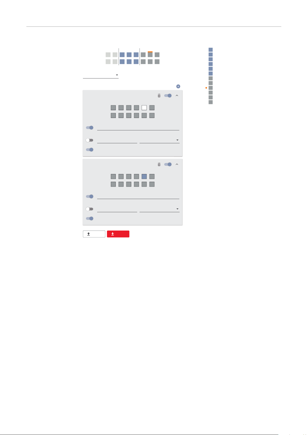
I/O power man-
DNO Rules
V+/GND IO I
not used
DNO Feedback
Rule 1
0 2 4 6 8 10
1 3 5 7 9 11
100
DNO Feedback
Active Power
1 cap
Power Factor (cos φ)
Rule 2
0 2 4 6 8 10
1 3 5 7 9 11
0
DNO Feedback
Active Power
1 cap
Power Factor (cos φ)
EXPORTIMPORT
0
0
2
3
4
5
6
7
8
9
10
11
1
2 4
1 3 5
6
9 117
108
v+ v+
GND GND
I/O Power Management
None
None
None
None
None
None
None
None
IO control
None
None
None
agement settings - 1 relay
92

Appendix
93

94

Status codes and remedy
EN
Status Codes
1006 – ArcDetected (operation LED: flashes yellow)
Cause:
Remedy:
1030 - WSD Open (operation LED: lights up red)
Cause:
Remedy:
OR:
OR:
Danger due to work that has been carried out incorrectly.
This can result in serious injury and damage to property.
Installing and connecting a surge protective device (SPD) must only be car-
▶
ried out by service personnel trained by Fronius and only within the scope of
the respective technical regulations.
Follow the safety rules.
▶
An arc was detected at a specific point on the PV system.
No action required. Feed-in mode is restarted again automatically
after 5 minutes.
A device connected in the WSD chain has interrupted the signal line
(e.g. a surge protective device) or the bypass ex works has been removed and no trigger device has been installed.
If the SPD surge protective device is triggered, the inverter must be
repaired by an authorised specialist.
Install the bypass ex works or a trigger device.
Set the WSD (wired shutdown) switch to position 1 (WSD primary
device).
WARNING!
1173 - ArcContinuousFault (operation LED: lights up red)
Cause:
Remedy:
OR:
OR:
Danger from damaged components of the photovoltaic system
This can result in severe personal injury/damage to property.
Before the status "1173 - ArcContinuousFault" is confirmed, the entire
▶
photovoltaic system in question must be checked for possible damage.
Have damaged components repaired by qualified personnel.
▶
An arc on the PV system was detected and the maximum number of
automatic switch-ons within 24 hours was reached.
Press and hold the sensor on the inverter for 3 seconds (max. 6
seconds).
Confirm the status "1173 - ArcContinuousFault" in the "System” →
"Event Log" menu area on the user interface of the inverter.
Confirm the status "1173 - ArcContinuousFault" in the "Notifica-
tions" user menu on the user interface of the inverter.
CAUTION!
95

Technical data
Tauro 50-3-D /
50-3-P
Input data
Maximum input voltage
1000 V
DC
(at 1000 W/m²/ -10 °C in an open circuit)
Start-up input voltage 200 V
MPP voltage range 400–870 V
DC
DC
Number MPP-controller 3
Maximum input current (I
DC max
PV1 / PV2 / PV3
per string (for D-version only)
Max. short circuit current 8) Total
PV1 / PV2 / PV3
per string (for D-version only)
Maximum PV field power (P
PV1 / PV2 / PV3
) Total
PV max
) Total
134 A
36 A / 36 A / 72 A
14.5 A / 22 A (30A fuses)
240 A
72 A / 72 A / 125 A
20 A / 30 A (30A fuses)
75 kWp
25 kWp / 25 kWp / 50
kWp
DC overvoltage category 2
Max. inverter backfeed current to the array
D-version PV1 / PV2 / PV3
P-version PV1 / PV2 / PV3
3)
72 / 72 / 125 A
0 / 0 / 0 A
4)
4)
Max. capacity of the PV generator against earth 10000 nF
Insulation resistance test limit value between PV
generator and earth (on delivery)
7)
Adjustable range of insulation resistance test
between PV generator and earth
6)
Limit value and tripping time of the sudden residual current monitoring (on delivery)
10–10000 kΩ
30 / 300 mA / ms
60 / 150 mA / ms
34 kΩ
90 / 40 mA / ms
Limit value and tripping time of the continuous re-
450 / 300 mA / ms
sidual current monitoring (on delivery)
Adjustable range of continuous residual current
monitoring
6)
Cyclic repetition of the insulation resistance test
30–1000 mA
24 h
(on delivery)
Adjustable range for the cyclic repetition of the
insulation resistance test
Output data
Grid voltage range 180–270 V
Rated grid voltage
220 VAC | 230 V
AC
AC
-
1)
96
Rated power 50 kW
Rated apparent power 50 kVA

Output data
Rated frequency
50 / 60 Hz
1)
Maximum output current / Phase 76 A
Initial short-circuit current / Phase IK“ 76 A
EN
Power factor (cos phi)
Grid connection 3~ NPE 380 / 220 V
3~ NPE 400 / 230 V
0–1 ind./cap.
AC
AC
Maximum output power 50 kW
Rated power 50 kW
Nominal output current / phase 75.8 A / 72.5 A
Total harmonic distortion < 3%
AC overvoltage category 3
Current (inrush)
5)
26.6 A rms over 3.2 ms
228 A peak /
4)
Max. output fault current per period 44.7 A / 16.24 ms
General data
Night-time power loss = standby consumption 15 W
European efficiency (400 / 600 / 800 / 870 VDC) 97.8 / 98.3 / 97.9 / 97.7%
Maximum efficiency 98.5%
Safety class 1
2)
EMC device class B
Pollution degree 3
Permitted ambient temperature
with built-in ‘AC disconnector’ option
- 40 °C – +65 °C
-30 °C – +65 °C
Permitted storage temperature - 40 °C – +70 °C
Relative humidity 0–100%
Sound pressure level (600 VDC) 68.4 dB(A) (ref. 20 µPa)
Protection class IP65
Dimensions (height x width x depth) 755 x 1109 x 346 mm
Weight 98 kg
Inverter topology Non-insulated trans-
formerless
Protection devices
DC disconnector Integrated
Cooling principle Controlled forced-air
ventilation
RCMU
9)
DC isolation measurement
9)
Integrated
Integrated
2)
Overload performance Operating point shift
power limitation
97

Protection devices
Active anti-islanding method Frequency conversion
method
Tauro Eco 50-3D / 50-3-P
Input data
Maximum input voltage
1000 V
DC
(at 1000 W/m²/ -10 °C in an open circuit)
Start-up input voltage 650 V
MPP voltage range 580–930 V
DC
DC
Number MPP-controller 1
Maximum input current (I
DC max
PV1 / PV2
per string (for D-version only)
Max. short circuit current 8) Total
PV1 / PV2
per string (for D-version only)
Maximum PV field power (P
PV1 / PV2
) Total
PV max
) Total
87.5 A
75 A / 75 A
14.5 A / 22 A (30A fuses)
178 A
125 A / 125 A
20 A / 30 A (30A fuses)
75 kWp
60 kWp / 60 kWp
DC overvoltage category 2
Max. inverter backfeed current to the array
3)
125 A
Max. capacity of the PV generator against earth 10000 nF
Insulation resistance test limit value between PV
generator and earth (on delivery)
7)
34 kΩ
4)
Adjustable range of insulation resistance test
between PV generator and earth
6)
Limit value and tripping time of the sudden residual current monitoring (on delivery)
10–10000 kΩ
30 / 300 mA / ms
60 / 150 mA / ms
90 / 40 mA / ms
Limit value and tripping time of the continuous re-
450 / 300 mA / ms
sidual current monitoring (on delivery)
Adjustable range of continuous residual current
monitoring
6)
Cyclic repetition of the insulation resistance test
30–1000 mA
24 h
(on delivery)
Adjustable range for the cyclic repetition of the
insulation resistance test
Output data
Grid voltage range 180–270 V
Rated grid voltage
220 VAC | 230 V
AC
AC
Rated power 50 kW
Rated apparent power 50 kVA
-
1)
98

Output data
Rated frequency
50 / 60 Hz
1)
Maximum output current / Phase 76 A
Initial short-circuit current / Phase IK“ 76 A
EN
Power factor (cos phi)
Grid connection 3~ NPE 380 / 220 V
3~ NPE 400 / 230 V
0–1 ind./cap.
AC
AC
Maximum output power 50 kW
Rated power 50 kW
Nominal output current / phase 75.8 A / 72.5 A
Total harmonic distortion < 3%
AC overvoltage category 3
Current (inrush)
5)
209 A peak /
30.5 A rms over 2.1 ms
Max. output fault current per period 37.2 A / 19.4 ms
General data
Night-time power loss = standby consumption 15 W
European efficiency (580 / 800 / 930 VDC) 98.2 / 97.7 / 97.3%
Maximum efficiency 98.5%
Safety class 1
2)
4)
EMC device class B
Pollution degree 3
Permitted ambient temperature
with built-in ‘AC disconnector’ option
- 40 °C – +65 °C
-30 °C – +65 °C
Permitted storage temperature - 40 °C – +70 °C
Relative humidity 0–100%
Sound pressure level (580 VDC) 68.5 dB(A) (ref. 20 µPa)
Protection class IP65
Dimensions (height x width x depth) 755 x 1109 x 346 mm
Weight 80 kg
Inverter topology Non-insulated trans-
formerless
Protection devices
DC disconnector Integrated
Cooling principle Controlled forced-air
ventilation
RCMU
9)
DC isolation measurement
9)
Integrated
Integrated
2)
Overload performance Operating point shift
power limitation
99

Protection devices
Active anti-islanding method Frequency conversion
method
AFCI (for D-version with 15/20 A fuses only) Optional
AFPE (AFCI) classification (acc. IEC63027)
(for D-version with 15/20 A fuses only)
9)
= F-I-AFPE-1-7/7-2
Full coverage
Integrated
AFPE
1 monitored string per in-
put port
7/7 input ports per chan-
nel (AFD1: 7, AFD2: 7)
2 monitored channels
Tauro Eco 99-3D / 99-3-P
Input data
Maximum input voltage
1000 V
DC
(at 1000 W/m²/ -10 °C in an open circuit)
Start-up input voltage 650 V
MPP voltage range 580–930 V
DC
DC
Number MPP-controller 1
Maximum input current (I
DC max
P-version PV1 / PV2
D-version PV1 / PV2 / PV3
per string (for D-version only)
) Total
175 A
100 A / 100 A
75 A / 75 A / 75 A
14.5 A / 22 A (30A fuses)
Max. short circuit current 8)
P-version total
D-version total
PV1 / PV2 / (PV3 for D-version only)
per string (for D-version only)
Maximum PV field power (P
PV max
) Total
P-version PV1 / PV2
D-version PV1 / PV2 / PV3
125 A / 125 A / 125 A
20 A / 30 A (30A fuses)
79 kWp / 79 kWp
57 kWp / 57 kWp / 57
250 A
355 A
150 kWp
kWp
DC overvoltage category 2
Max. inverter backfeed current to the array
P-version total
D-version total
3)
125 A
250 A
4)
4)
100
Max. capacity of the PV generator against earth 19998 nF
Insulation resistance test limit value between PV
generator and earth (on delivery)
7)
Adjustable range of insulation resistance test
between PV generator and earth
6)
Limit value and tripping time of the sudden residual current monitoring (on delivery)
10–10000 kΩ
30 / 300 mA / ms
60 / 150 mA / ms
34 kΩ
90 / 40 mA / ms
Limit value and tripping time of the continuous re-
900 / 300 mA / ms
sidual current monitoring (on delivery)
 Loading...