

Page 1

/ Perfect Charging / Perfect Welding / Solar Energy
FIND YOUR
FIND YOUR
OPERATING MANUALS
OPERATING MANUALS
www.fronius-usa.com/inverter-manuals
www.fronius.com/energy-package-manuals
Fronius Symo Hybrid
with external battery
Installations instructions
EN
System monitoring
42,0426,0303,EN 015-12082019
Page 2

2
Page 3

Contents
Connecting the external battery to the Fronius Symo Hybrid .................................................................... 5
Components.......................................................................................................................................... 5
Fronius Checkbox 500V........................................................................................................................ 5
External battery..................................................................................................................................... 5
Fronius Checkbox 500V technical data ................................................................................................ 6
Fronius Checkbox 500V status LED ..................................................................................................... 6
Installing the Fronius Symo Hybrid with the external battery ..................................................................... 7
Tips before commissioning ................................................................................................................... 7
Commissioning .................................................................................................................................... 7
Maximum clearances between the components .................................................................................. 7
Modbus cabling and terminating resistors ............................................................................................ 8
Data cables in the third-party battery .................................................................................................... 8
Installing the Fronius Checkbox................................................................................................................. 9
Safety.................................................................................................................................................... 9
Mounting and connecting up the Fronius Checkbox 500V ................................................................... 10
Installing the ferrite ring for the data line............................................................................................... 10
Installing and configuring Fronius system monitoring ................................................................................ 11
Safety.................................................................................................................................................... 11
Starting for the first time........................................................................................................................ 11
Information to help you work through the technician wizard ................................................................. 13
Software version of the Fronius system monitoring ..............................................................................14
Updating the firmware via the Web....................................................................................................... 15
Performing a third-party battery software update.................................................................................. 15
Fronius system monitoring settings ........................................................................................................... 17
Settings on the Fronius system monitoring website..............................................................................17
Creating IO mapping............................................................................................................................. 17
System monitoring settings................................................................................................................... 17
Troubleshooting ......................................................................................................................................... 18
Troubleshooting .................................................................................................................................... 18
EN
3
Page 4

4
Page 5

Connecting the external battery to the Fronius Symo
Hybrid
Components
Solar module
Generates direct current
Inverter – Fronius hybrid
Converts the direct current into alternating current and charges the battery.
Thanks to the built-in system monitoring function, the inverter can be integrated into a network using WLAN technology.
Fronius Checkbox 500V
Needed to establish a secure connection between the inverter and the battery.
CHECKBOX 500V
Third-party battery
Connected on the DC side to the Checkbox and the inverter and stores
electrical energy.
Photovoltaic system consumers
The consumers connected to the PV system (single or three-phase)
EN
Fronius Checkbox 500V
Meter – Fronius Smart Meter
For optimum energy management. You can have the meter installed in a
switch cabinet by your electrical installer.
Grid
The Fronius Checkbox 500V connects the Fronius Symo Hybrid to an external battery. The
inverter and battery must never be directly connected to each other, as an error could lead
to surges that place the system in an unsafe state.
There are separate Installation Instructions for the battery and the Fronius Symo Hybrid.
This document is concerned only with the specifics of establishing a connection to the Fronius Checkbox 500V. The remaining steps for installing the equipment can be found in the
respective Installation Instructions. All Fronius documents are available at the following address: www.fronius.com/energy-package-manuals
External battery Fronius points out that the external batteries are not Fronius products. Moreover, Fronius
is not the distributor of these batteries. Therefore, Fronius does not assume any liability or
guarantee for these batteries.
5
Page 6

Fronius Checkbox 500V technical data
Environmental conditions
Degree of protection IP65
Permissible ambient temperature -25 °C - +60 °C
Maximum altitude 2000 m
Permitted humidity 0 - 100% (non-condensing)
Electrical specifications
Maximum input voltage
Inverter side
Battery side
Maximum current Idc max in / max out 16 A
Self-consumption @ 450 V 1.9 W
Dimensions and weight
Dimensions h x w x d (without packaging) 26 x 19 x 7.5 cm
Weight (without packaging) 1.4 kg
Dimensions h x w x d (with packaging) 36 x 30 x 13 cm
Weight (with packaging) 1.9 kg
Standards and directives
Applicable standards and directives LVD (2014/53/EU), IEC 62109-1
Udc max in_INV
Udc max out_BAT
1000 V
500 V
Fronius Checkbox 500V status
LED
When the status LED lights up green, an electrical connection has been
established between the inverter and the battery.
6
Page 7

Installing the Fronius Symo Hybrid with the external
battery
Tips before commissioning
Commissioning
EN
It can take up to two hours to update the inverter. During this time the inverter must be connected to an AC power source. To save time during installation, work may still be carried
out in a non-live area of the system while the update is in progress.
More information on the update process can be found under "Software version of the
Fronius system monitoring" on page 14
IMPORTANT!
Failure to follow these steps in the correct order will not only invalidate the warranty,
but also risks a deep discharge of the battery.
IMPORTANT!
If the installation cannot be completed in one attempt, precautions must be taken to
prevent a deep discharge of the battery (see the battery Installation Instructions).
Maximum clearances between
the components
Observe the enclosed complete circuit diagram for the entire system during commissioning.
Set up the entire system in the following order:
1. Install the inverter (Fronius Hybrid series)
2. Install the Fronius Smart Meter
3. Install the Fronius Checkbox and external battery
(for more information on installing the Fronius Checkbox, see section Installing the
Fronius Checkbox on page 9)
4. Launch and complete the Setup wizard (wizard on the inverter)
5. Configure communication between the battery and the inverter
6. Carry out a function test
max. 1 m max. 9 m
7
Page 8
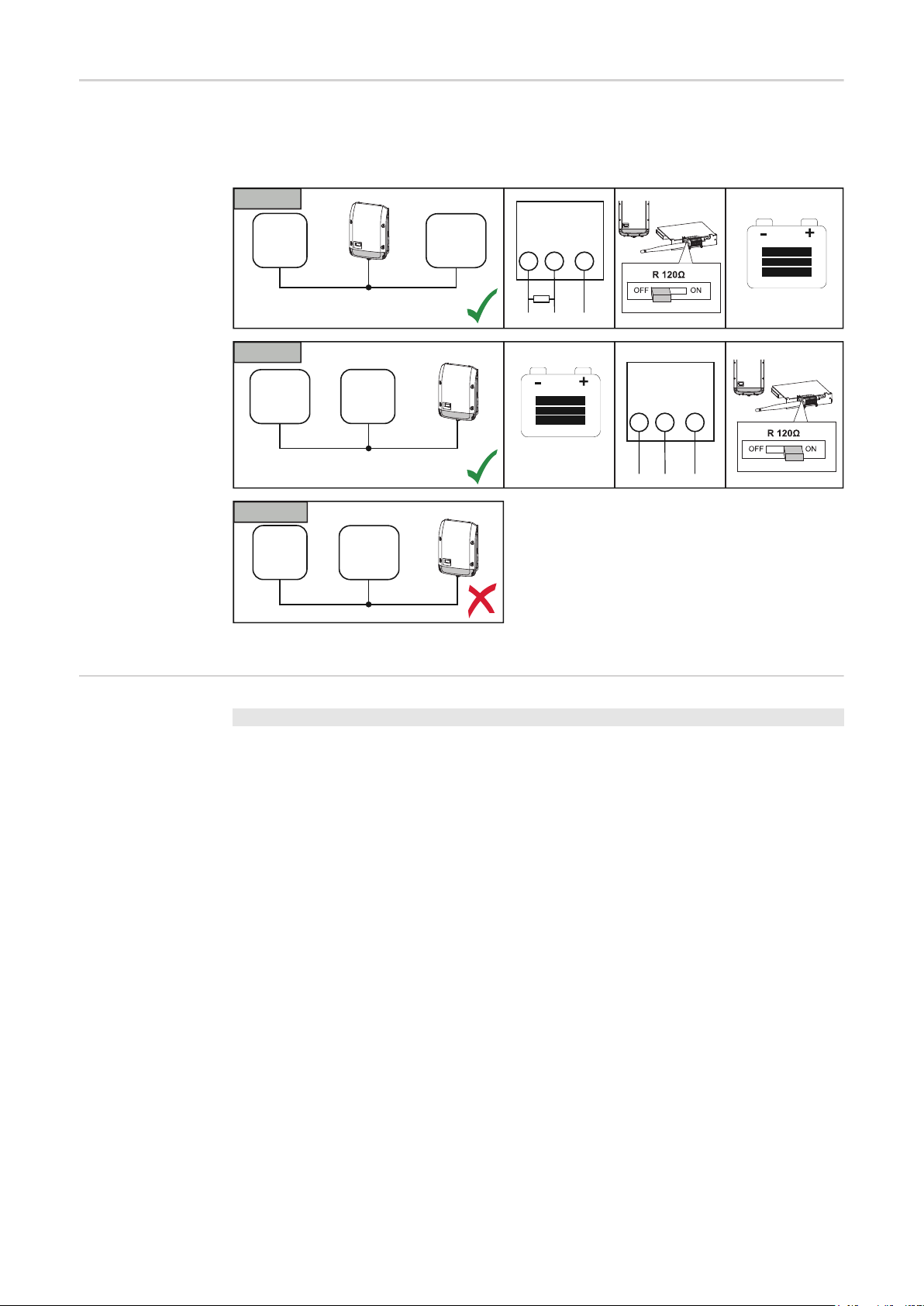
Modbus cabling
OPTION 1
NO OPTION
OPTION 2
and terminating
resistors
A terminating resistor must be used on the outer components of the Modbus cabling. The
location of the terminating resistor on the external battery is fixed, meaning that the battery
cannot be installed in the middle of the Modbus.
OPTION 1
Fronius
Smart
Meter
OPTION 2
Battery
Battery
Data (Recommended cable:
Li2YCY(TP) or CAT6a)
Fronius
Smart
Meter
OUTPUT
RS 485
D+ / D- -
33 34 35
120 Ω
*)
OUTPUT
RS 485
D+ / D- -
33 34 35
Data (Recommended cable:
Li2YCY(TP) or CAT6a)
NO OPTION
Fronius
Smart
Meter
*) The R 120 Ohm terminating resistor is supplied with the Fronius Smart Meter
Battery
Data cables in the
third-party battery
LG Chem ResuH Fronius Symo Hybrid Fronius Smart Meter
EN GND - (GND) C
ENABLE_H IO 1
RS485_L D- B
RS485_H D+ A
8
Page 9

Installing the Fronius Checkbox
EN
Safety
WARNING!
Operating the equipment incorrectly or poor workmanship can cause serious injury
or damage.
Commissioning of the hybrid system may only be carried out by trained personnel in accordance with the technical regulations. Read the Installation Instructions and the Operating Instructions of the Fronius Symo Hybrid and the battery before carrying out any
installation or commissioning work.
WARNING!
An electric shock can be fatal.
Danger due to DC voltage from the inverter and the battery.
► Always make sure the inverter is disconnected and de-energised before carrying out
any connection work.
► Check that the battery is de-energised. The battery should be de-energised when it is
delivered.
► Only an authorised electrical engineer is permitted to connect this equipment to the
public grid.
IP65
NH
3
Possible assembly positions when using outdoors:
> 2000 m
2000 m
0 m
9
Page 10

Mounting and
6 mm
connecting up the
Fronius Checkbox 500V
NOTE!
Risk of damage to the device.
Do not mix up the DC connections of the battery and the inverter.
Observe the enclosed complete circuit diagram when connecting up the Fronius checkbox.
Mount the supplied mounting bracket to the wall using suitable screws and wall plugs
1
Attach the Fronius Checkbox, push it down, and secure using the screw supplied
2
1 2
3
4
only original MC4
Installing the ferrite ring for the
data line
min 4 mm²
2
1
4
3
min 2,5 mm²
double insulated
-
1
1000 V
+
2
3
4
+
-
The data line between the inverter and the battery must be fitted with a ferrite ring as close
as possible to each of the two terminal connections in order to avoid electromagnetic interference.
One ferrite ring is supplied with the Fronius Symo Hybrid and one is supplied with the Fronius Checkbox (Würth ferrite ring - item number: 74271132S).
Fit a ferrite core to the data line ahead of the terminal connection in the inverter
1
Remove the insulation from the data line ahead of the battery terminal connection and
2
loop the line through the ferrite core twice
10
Page 11

Installing and configuring Fronius system monitoring
Safety
Starting for the
first time
EN
WARNING!
Danger from incorrect operation
This can result in severe personal injury and damage to property.
► Do not use the functions described here until you have fully read and understood the
Operating Instructions of every system component:
► Do not use the functions described here until you have read and understood all the
safety rules.
IMPORTANT! Knowledge of networking systems is required in order to install Fronius system monitoring.
IMPORTANT! Starting up the Fronius system monitoring function for the first time is made
considerably easier with the Fronius Solar.web app. The Fronius Solar.web app is available in the respective app stores.
Or visit
https://wizard.solarweb.com
IMPORTANT! In order to establish a connection to Fronius system monitoring, the end device in question (e.g. laptop, tablet, etc.) must be set up as follows:
- "Obtain IP address automatically (DHCP)" must be activated
Switch the device to Service mode
1
- Activate the WLAN Access Point via the Setup menu on the inverter
Standby
WiFi Access Point
Relay
Clock
Relay
Display Setting
The inverter establishes the WLAN access point. The WLAN access point remains open
for 1 hour.
11
Page 12

Installation using the Solar.web app Installation using a web browser
Download the Fronius Solar.web App
2
Run the Fronius Solar.web app
3
The Setup wizard start page is displayed.
Connect the end device to the WLAN
2
access point
SSID = FRONIUS_239.xxxxx (4-8
digits)
- Search for a network with the
name "FRONIUS_239.xxxxx"
- Establish a connection to this
network
- Enter the password 12345678
(Alternatively, connect the end device
and inverter using an Ethernet cable.)
Enter the following in the browser:
3
http://datamanager
or
192.168.250.181 (IP address for
WLAN connection)
or
169.254.0.180 (IP address for LAN
connection)
12
If you run the technician wizard, always remember to make a note of the assigned service
password. This service password is required to enter settings in the "System overview" and
"DNO Editor" menus as well as for advanced battery settings.
If the technician wizard is not run, no specifications regarding power reduction are set and
hybrid mode is not possible (charging and discharging of the battery)
Run the technician wizard and follow the instructions
4
Page 13

IMPORTANT!
Information to
help you work
through the technician wizard
Danger of deep discharge of an unactivated battery
This may result in permanent damage to the battery.
► The Solar Web wizard needs to be run in order to activate the battery and, if necessary,
the Smart Meter.
Run the solar web wizard and follow the instructions
5
The Fronius Solar.web homepage
or
the Fronius system monitoring web page is displayed.
The description below only applies to technician wizards for inverters with software version
1.9.x-x or higher. Thus, IO and battery mapping are not possible. Only once the software
has been updated (see "Updating the firmware via the Web" on page 15) can the settings be changed in the web interface under "IO mapping" (see "Creating IO mapping" on
page 17) and "System overview" (see "System monitoring settings" on page 17).
The technician wizard consists of 5 steps:
1. General
General system data (e.g. system name) is entered here
EN
2. Service password
Enter (and make a note of) the service password.
13
Page 14
3. IO mapping
Settings for the IO interface are entered (also see Creating IO mapping on page 17)
4. System overview
Settings for the entire PV system are entered (see also System monitoring settings on
page 17)
Software version
of the Fronius
system monitoring
5. Dynamic power
Enter the settings for the dynamic power reduction
Software version 1.9.x-x or higher is required to support third-party batteries. There must
be an internet connection for the duration of the update process. The current version of the
system monitoring software can be viewed by clicking on the info symbol:
14
Page 15

Regardless of the software version shown in the web interface, it may take several update
steps before the software is updated to the latest version. Both the inverter and the battery
can be updated at the same time.
EN
Updating the firmware via the Web
Performing a
third-party battery software update
Use your web browser to open the Fronius system monitoring web page.
1
Open “Firmware update” under “Services”.
2
Select 'Update via Web'
3
Click the 'Run update' button.
4
A confirmation prompt for the update is displayed.
Click the 'Yes' button
5
The update is performed and progress is indicated in the form of a bar and as a percentage.
If the connection to the server fails:
- Deactivate the firewall for the amount of time required to complete the update.
- Try again.
IMPORTANT! If a proxy server is being used to establish the Internet connection:
- You must activate the “Use proxy server for Web update” option.
- You must enter the data required.
CAUTION!
Risk of damage to the battery! If the battery software update process is interrupted,
this may result in damage to the battery.
In order to avoid this, during the update:
► Do not switch off the inverter
► Do not switch off the battery
► Maintain the recommended state of charge (SoC) of over 50% on the battery
► Ensure a steady mains supply
► Ensure and do not interrupt Modbus communication
CAUTION!
Risk of damage to the battery! If, despite safety precautions, the update process is
still interrupted, follow the steps for turning off the battery as outlined by the thirdparty battery manufacturer and in the correct order. Then immediately consult the
third-party battery manufacturer
to avoid long-term damage. A battery in standby mode can become permanently damaged
in just a few days due to self discharge.
As soon as the battery software needs to be updated, a message will appear on the system
monitoring website.
Click the message stating that the battery software needs to be updated
1
15
Page 16

A page containing a variety of setting options appears.
2
Under "Update", select "Local" and click on "Run update"
The update will start and run to completion. This can take up to an hour.
3
Wait until the end of the update.
A message will appear stating that the update was successful.
4
Confirm the message by clicking "OK".
16
Page 17

Fronius system monitoring settings
EN
Settings on the
Fronius system
monitoring website
Creating IO mapping
If the battery is installed at a later date or the inverter was only updated to software version
1.9.x-x after the system had already been commissioned, several settings will need to be
changed on the system monitoring website. In the "IO mapping" section, a pin must be selected under "Energy storage system". The battery must be selected in the "System overview" area.
Enable "Energy storage system" under Settings - IO mapping. The pin assignment
1
must match the cabling.
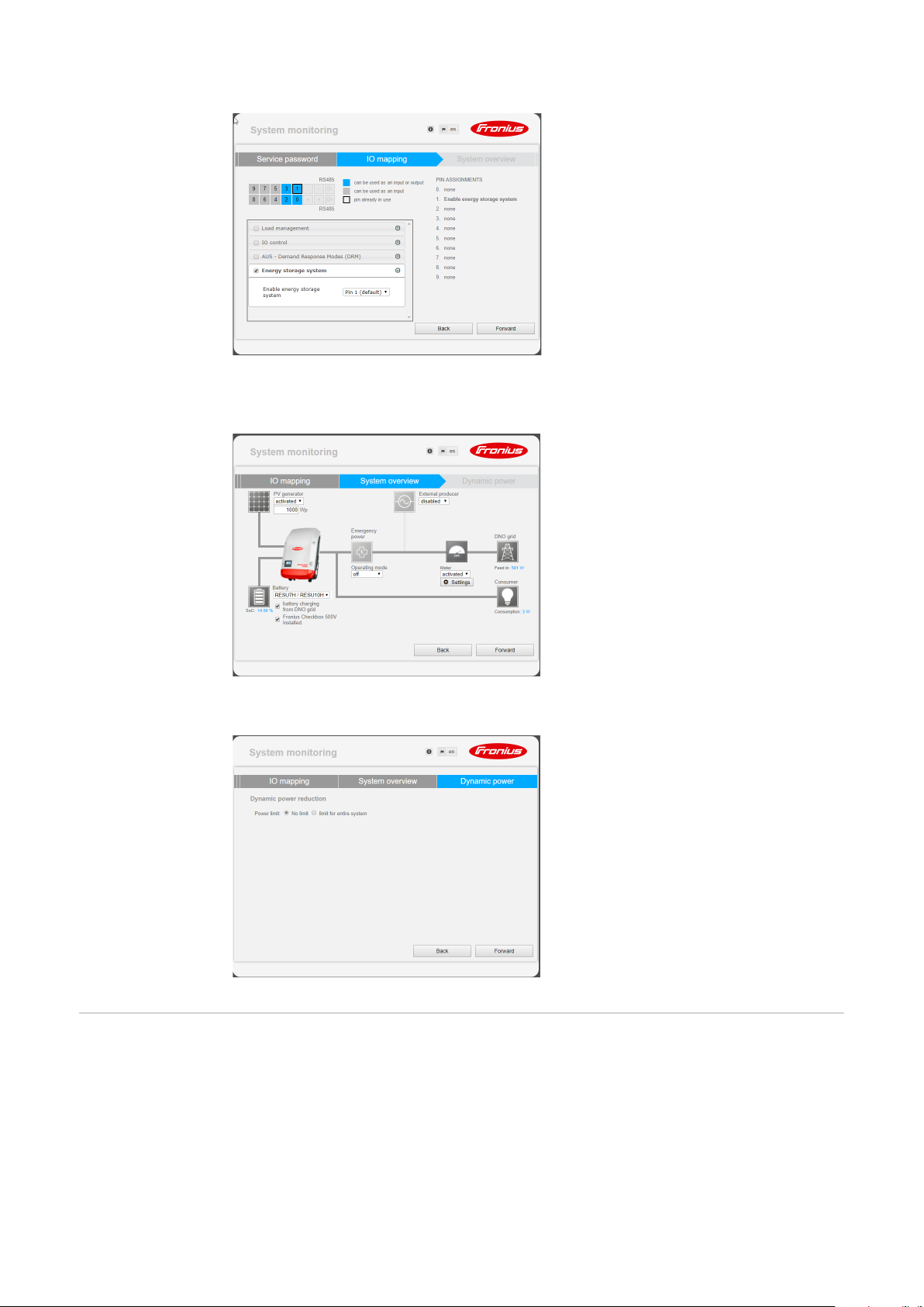
System monitoring settings
Select "RESU7H / RESU10H" in the Battery field under Settings - System overview
1
Select "activated" in the Meter field. The meter position must be selected under Set-
2
tings depending on the installation (consumption branch or feed-in point)
If the Checkbox has been installed correctly, check the box next to "Fronius Checkbox
3
500V installed"
17
Page 18

Troubleshooting
Troubleshooting Battery is permanently in energy saving mode (error message 65000)
Behaviour The battery goes into energy saving mode and can no longer be activated by
the inverter
Remedy Check if the DC main switch on the battery has been switched on
Remedy Check if the DC main switch on the inverter has been switched on
Remedy Check the cabling between the inverter, Checkbox and battery
Remedy Restart the Datalogger (click the "Datalogger restart" button on the system
monitoring website under "System information") - the ON LED on the battery
goes green. When switching on, check that the green LED on the Checkbox
also comes on.
Remedy Using the display, place the inverter in standby mode for ten seconds - the ON
LED on the battery will go green. When switching on, check that the green
LED on the Checkbox also comes on.
18
Page 19

EN
19
Page 20

Other Languages
Deutsch
Deutsch www.fronius.com/QR-link/4204260303DE
English www.fronius.com/QR-link/4204260303EN
Ceština www.fronius.com/QR-link/4204260303CS
Italiano www.fronius.com/QR-link/4204260303IT
Français www.fronius.com/QR-link/4204260303FR
Español www.fronius.com/QR-link/4204260303ES
Dansk
Dansk www.fronius.com/QR-link/4204260303DA
Svensk www.fronius.com/QR-link/4204260303SV
Polski www.fronius.com/QR-link/4204260303PL
Português www.fronius.com/QR-link/4204260303PB
Magyar www.fronius.com/QR-link/4204260303HU
Türk www.fronius.com/QR-link/4204260303TR
English
Svensk
Ceština
Polski
Italiano
Português
Français
Magyar
Español
Türk
Slovenský
Slovenský www.fronius.com/QR-link/4204260303SK
Nederlands www.fronius.com/QR-link/4204260303NL
İȜȜȘȞȚțȐ www.fronius.com/QR-link/4204260303EL
Român www.fronius.com/QR-link/4204260303RO
Nederlands
İȜȜȘȞȚțȐ
Român
Fronius Worldwide - www.fronius.com/addresses
Fronius International GmbH
4600 Wels, Froniusplatz 1, Austria
E-Mail: pv-sales@fronius.com
http://www.fronius.com
Fronius USA LLC Solar Electronics Division
6797 Fronius Drive, Portage, IN 46368
E-Mail: pv-us@fronius.com
http://www.fronius-usa.com
8QGHUKWWSZZZIURQLXVFRPDGGUHVVHV\RXZLOO¿QGDOODGGUHVVHVRIRXUVDOHVEUDQFKHVDQGSDUWQHU¿UPV
 Loading...