

Page 1

Operating
Instructions
Fronius Symo GEN24
6.0 / 6.0.Plus / 8.0 / 8.0 Plus
10.0 / 10.0 Plus
Operating Instructions
EN
42,0426,0315,EN 019-18042023
Page 2

Page 3

Contents
Safety rules 8
Explanation of safety notices 8
Safety 8
General 8
Environmental conditions 9
Qualified personnel 9
Noise emission values 9
EMC measures 10
Backup power 10
Data protection 11
Copyright 11
Protective earthing (PE) 11
General information 13
Fronius Symo GEN24 15
Device concept 15
Function overview 15
Fronius UP 16
Scope of supply 16
Intended use 16
Thermal concept 17
Fronius Solar.web 17
Local communication 18
The various operating modes 19
Operating modes – Explanation of symbols 19
Operating mode – Inverter with battery 20
Operating mode – Inverter with battery and several Smart Meters 20
Operating mode - inverter with battery, AC-coupled to another inverter 20
Operating mode – Inverter with battery and backup power function 21
Operating mode – Inverter with battery and Ohmpilot 21
Operating mode – Inverter with battery, Ohmpilot and backup power function 21
Operating mode – Inverter with battery and additional inverter 22
Operating mode – Inverter with battery, further inverter and backup power function 22
Energy flow direction of the inverter 23
Operating states (only for systems with a battery) 23
Energy saving mode 25
General 25
Switch-off conditions 25
Switch-on conditions 25
Special case 25
Indication of energy saving mode 26
Suitable batteries 27
General 27
BYD Battery-Box Premium 27
LG RESU FLEX 28
Manual system start 30
Requirements 30
Notification of system shutdown 30
Manual battery start after system shutdown 30
Starting backup power operation after a system shutdown 30
Protection of people and equipment 31
Central grid and system protection 31
WSD (wired shutdown) 31
RCMU 31
Safe state 31
Surge protective device 31
Control elements and connections 32
Connection area 32
EN
3
Page 4

Connection area divider 33
Ground electrode terminal 33
DC disconnector 34
Data communication area 34
Button functions and LED status indicator 36
Internal schematic connection diagram of the IOs 37
Backup power variant - PV Point (OP) 39
General 41
PV Point (OP) 41
Explanation - PV Point (OP) 41
Backup power variant - Full Backup 43
General 45
Prerequisites for backup power mode 45
Transitioning from feeding energy into the grid to backup power mode 45
Transitioning from backup power mode to feeding energy into the grid 45
Backup power and energy saving mode 46
Cabling variants including backup power circuits with 3-pin separation e.g. Austria or Australia
Functions 47
Transitioning from feeding energy into the grid to backup power mode 47
Transitioning from backup power mode to feeding energy into the grid 47
All-pin separation cabling variant e.g. Germany, France 48
Functions 48
Transitioning from feeding energy into the grid to backup power mode 48
Transitioning from backup power mode to feeding energy into the grid 49
All-pin separation cabling variant, Italy 50
Functions 50
Transitioning from feeding energy into the grid to backup power mode 50
Transitioning from backup power mode to feeding energy into the grid 51
47
Installation 53
General 55
Quick-lock system 55
Warning notices on the device 55
System component compatibility 56
Installation location and position 57
Choosing the location of the inverter 57
Choosing the location of third-party batteries 58
Installation position of inverter 58
Install the mounting bracket and hang up the inverter 60
Selecting the fixing material 60
Properties of the mounting bracket 60
Do not deform the mounting bracket 60
Fitting the mounting bracket to a wall 60
Installing the mounting bracket on a mast or beam 61
Attaching the mounting bracket to mounting rails 62
Attaching the inverter to the mounting bracket 62
Prerequisites for connecting the inverter 63
Permissible cables for the electrical connection 63
Permitted cables for the data communication connection 63
Cross section of the AC cable 64
Cross section of the DC cable 65
Maximum alternating current fuse protection 65
Connecting the inverter to the public grid (AC side) 66
Safety 66
Connecting the inverter to the public grid (AC side) 66
Connecting solar module strings to the inverter 69
General comments regarding PV modules 69
Safety 69
4
Page 5

Module array - general information 70
Module array configuration6 - 10 kW 70
Connecting the solar module strings to the inverter 71
Connecting the battery to the inverter 75
Safety 75
Connecting the battery on the DC side 75
Connecting the LG RESU FLEX ground conductor 79
Connecting backup power - PV Point (OP) 80
Safety 80
Installation 80
Connecting backup power - Full Backup 85
Safety 85
Cabling variants including backup power circuits with 3-pin separation e.g. Austria or Aus-
tralia
All-pin separation cabling variant e.g. Germany, France, Spain 86
All-pin separation cabling variant, e.g. Italy 87
Testing backup power mode 88
Connecting the data communication cable 89
Modbus participants 89
Routing data communication cables 90
Connecting the battery communication cable 92
Terminating resistors 92
Installing the WSD (wired shutdown) 94
Closing and commissioning the inverter 95
Closing the inverter's connection area/housing cover, and commissioning 95
Starting the inverter for the first time 95
Installation with the app 96
Installation using the web browser 96
Switching off current supply and restarting the inverter 98
De-energising the inverter and switching it on again 98
85
EN
Settings - user interface of the inverter 99
User settings 101
User login 101
Selecting the language 101
Device configuration 102
Components 102
Functions andI/Os 103
Demand Response Modes (DRM) 104
Inverter 104
Energy management 107
Energy management 107
Examples - Time-dependent battery control 108
Allowed battery control rules 110
PV power reduction 112
Load management 112
System 114
General 114
Update 114
Setup wizard 114
Restoring the factory settings 114
Event log 114
Information 114
Licence manager 115
Support 116
Communication 117
Network 117
Modbus 118
Remote control 119
Fronius Solar API 119
Safety and grid requirements 121
5
Page 6

Country setup 121
Feed-in limitation 121
Dynamic power regulation with several inverters 123
I/O power management 126
Connection diagram - 4 relay 127
I/O power management settings - 4 relays 128
Connection diagram - 3 relay 129
I/O power management settings - 3 relays 130
Connection diagram - 2 relay 131
I/O power management settings - 2 relays 132
Connection diagram - 1 relay 133
I/O power management settings - 1 relay 134
Autotest(CEI 0-21) 134
Options 137
Surge protective device (SPD) 139
General 139
Safety 139
Scope of supply 139
De-energising the inverter 140
Installation 141
Commissioning the inverter 146
DC Connector Kit GEN24 148
General 148
General comments regarding PV modules 148
Safety 148
Scope of supply 149
De-energising the inverter 149
Installation 150
Commissioning the inverter 154
Appendix 155
Care, maintenance and disposal 157
General 157
Maintenance 157
Cleaning 157
Safety 157
Operation in dusty environments 157
Disposal 158
Guarantee provisions 160
Fronius manufacturer's warranty 160
Components for automatic Full Backup backup power changeover 161
Components for automatic Full Backup backup power changeover 161
Status codes and remedy 163
Display 163
Status Codes 163
Technical data 164
Fronius Symo GEN24 6.0 / 6.0 Plus 164
Fronius Symo GEN24 8.0 / 8.0 Plus 167
Fronius Symo GEN24 10.0 / 10.0 Plus 171
WLAN 174
Technical data of surge protective device DC SPD type 1+2 GEN24 175
Explanation of footnotes 175
Integrated DC disconnector 176
Circuit diagrams 177
Circuit Diagram - PV Point (OP) 179
Circuit Diagram 179
Circuit Diagram - PV Point (OP) Australia 180
Circuit Diagram 180
Fronius Symo GEN24 and BYD Battery-Box Premium HV 181
6
Page 7

Circuit Diagram 181
Fronius Symo GEN24 with two BYD Battery-Box Premium HV connected in parallel 182
Circuit Diagram 182
Fronius Symo GEN24 with three BYD Battery-Box Premium HV connected in parallel 183
Circuit Diagram 183
Fronius Symo GEN24 and LG RESU FLEX 184
Circuit Diagram 184
Automatic switch to backup power 3-pin double FRT-capable separation - e.g. Austria 185
Circuit Diagram 185
Automatic switch to backup power 3-pin double separation - e.g. Austria 186
Circuit Diagram 186
Automatic switch to backup power 3-pin single separation- e.g. Australia 187
Circuit Diagram 187
Automatic switch to backup power 3-pin double separation with ext. Grid and system protection
Circuit Diagram 188
Automatic switch to backup power 4-pin double separation - e.g. Germany 189
Circuit Diagram 189
Automatic switch to backup power 4-pin single separation- e.g. France, Spain 190
Circuit Diagram 190
Automatic switch to backup power 4-pin double separation with ext. grid and system protection - e.g. Italy
Circuit Diagram 191
Wiring diagram - surge protective device SPD 192
Circuit Diagram 192
188
191
EN
Dimensions of the inverter 193
Fronius Symo GEN24 6 -10 kW 195
Fronius Symo GEN24 6 - 10 kW 195
7
Page 8

Safety rules
Explanation of
safety notices
Safety
WARNING!
Indicates a potentially hazardous situation.
Death or serious injury may result if appropriate precautions are not taken.
▶
CAUTION!
Indicates a situation where damage could occur.
If not avoided, minor injury and/or damage to property may result.
▶
NOTE!
Indicates a risk of flawed results and possible damage to the equipment.
If you see any of the symbols depicted in the "Safety rules" chapter, special care
is required.
CAUTION!
Danger from crushing due to the incorrect handling of attachments and connection parts.
Injuries to limbs may result.
When lifting up, putting down and attaching the inverter, use the integrated
▶
grips.
When fitting attachments, ensure that no limbs are located between the at-
▶
tachment and the inverter.
Do not hold onto the individual poles on the terminals when locking and un-
▶
locking.
General The device has been manufactured in line with the state of the art and according
to recognised safety standards. In the event of incorrect operation or misuse,
there is a risk of
Injury or death to the operator or a third party
-
Damage to the device and other material assets belonging to the operating
-
company
All personnel involved in commissioning, maintenance, and servicing of the
device must:
Be suitably qualified
-
Have knowledge of and experience in dealing with electrical installations
-
Have fully read and precisely followed these Operating Instructions
-
In addition to the Operating Instructions, all applicable local rules and regulations regarding accident prevention and environmental protection must also be
followed.
8
Page 9

All safety and danger notices on the device:
Must be kept in a legible state
-
Must not be damaged
-
Must not be removed
-
Must not be covered, pasted, or painted over
-
Only operate the device when all protection devices are fully functional. If the
protection devices are not fully functional, there is a danger of
Injury or death to the operator or a third party
-
Damage to the device and other material assets belonging to the operating
-
company
Any safety devices that are not fully functional must be repaired by an authorized specialist before the device is switched on.
Never bypass or disable protection devices.
For the location of the safety and danger notices on the device, refer to the
chapter headed "Warning notices on the device" in the Operating Instructions for
your device.
Faults that could compromise safety must be remedied before switching on the
device.
EN
Environmental
conditions
Qualified personnel
Operation or storage of the device outside the stipulated area will be deemed as
not in accordance with the intended purpose. The manufacturer accepts no liability for any damage resulting from improper use.
The servicing information contained in these operating instructions is intended
only for the use of qualified service engineers. An electric shock can be fatal. Do
not carry out any actions other than those described in the documentation. This
also applies to qualified personnel.
All cables and leads must be secured, undamaged, insulated and adequately dimensioned. Loose connections, scorched, damaged or inadequately dimensioned
cables and leads must be immediately repaired by authorised personnel.
Maintenance and repair work must only be carried out by an authorised specialist.
It is impossible to guarantee that bought-in parts are designed and manufactured to meet the demands made on them, or that they satisfy safety requirements. Use only original spare parts (also applies to standard parts).
Do not carry out any alterations, installations, or modifications to the device
without first obtaining the manufacturer's permission.
Components that are not in perfect condition must be changed immediately.
Noise emission
values
The sound power level of the inverter is specified in the Technical data.
The device is cooled as quietly as possible with the aid of an electronic temperature control system; this depends on the amount of converted power, the ambient
temperature, the level of soiling of the device, etc.
It is not possible to provide a workplace-related emission value for this device
because the actual sound pressure level is heavily influenced by the installation
9
Page 10

situation, the grid quality, the surrounding walls and the properties of the room
in general.
EMC measures In certain cases, even though a device complies with the standard limit values for
emissions, it may affect the application area for which it was designed (e.g., when
there is equipment that is susceptible to interference at the same location, or if
the site where the device is installed is close to either radio or television receivers). If this is the case, then the operator is obliged to take action to rectify the
situation.
Backup power This system has backup power functions. This enables a replacement power sup-
ply to be established in the event of a failure in the public grid.
Where an automatic backup power supply is installed, a backup power warning
notice (https://www.fronius.com/en/search-page, item number: 42,0409,0275)
must be fitted on the electrical distributor.
Maintenance and installation work in the home network requires both disconnection on the utility side and deactivation of the replacement power mode by opening the integrated DC disconnector on the inverter.
Depending on the insolation conditions and the battery state of charge, the
backup power supply is automatically deactivated and activated. This can cause
the backup power supply to unexpectedly return from standby mode. Therefore,
installation work can only be performed on the home network when the backup
power supply is deactivated.
Influencing factors on the total power in backup power mode:
Reactive power
Electrical loads with a power factor not equal to 1 also require reactive power in
addition to effective power. The reactive power also loads the inverter. Therefore,
to correctly calculate the actual total power, it is not the rated power of the load
that is relevant, but the current caused by effective and reactive power.
Devices with a high reactive power are mainly electric motors such as:
Water pumps
-
Circular saws
-
Blowers and fans
-
High starting current
Electrical loads that need to accelerate a large mass usually require a high starting current. This can be up to 10 times higher than the nominal current. The maximum current of the inverter is available for the starting current. Loads with too
high starting currents therefore cannot be started/operated, even though the
nominal power of the inverter suggests that they can. When dimensioning of the
backup power circuit, the connected load power and any starting current must
also be taken into account.
10
Devices with high starting currents are, for example:
Devices with electric motors (e.g. lifting platform, circular saws, planing
-
bench)
Devices with large transmission ratio and flywheel mass
-
Devices with compressors (e.g. compressed air compressors, air conditioning
-
systems)
IMPORTANT!
Very high starting currents can cause short-term distortion or a drop in output
Page 11

voltage. The simultaneous operation of electronic devices in the same backup
power supply system should be avoided.
Load unbalance
When dimensioning three-phase backup power networks, the total output power
and the power output per phase of the inverter must be taken into account.
IMPORTANT!
The inverter may only be operated within the limits of its technical capabilities.
Operation outside of its technical capabilities can cause the inverter to shut
down.
Data protection The user is responsible for the safekeeping of any changes made to the factory
settings. The manufacturer accepts no liability for any deleted personal settings.
Copyright Copyright of these operating instructions remains with the manufacturer.
The text and illustrations are all technically correct at the time of printing. We
reserve the right to make changes. The contents of the operating instructions
shall not provide the basis for any claims whatsoever on the part of the purchaser. If you have any suggestions for improvement, or can point out any mistakes that you have found in the instructions, we will be most grateful for your
comments.
EN
Protective
earthing (PE)
Connection of a point in the device, system or installation to earth to protect
against electric shock in the event of a fault. When installing a safety class 1 inverter (see Technical data), the ground conductor connection is required.
When connecting the ground conductor, ensure that it is secured against accidental disconnection. All the points listed in the chapter Connecting the invert-
er to the public grid (AC side) on page 66 must be observed. It must be ensured
that when using the strain relief devices, the ground conductor is the last to be
disconnected in the event of a possible failure. When connecting the ground conductor, the minimum cross-section requirements specified by the respective national standards and guidelines must be observed.
11
Page 12

12
Page 13

General information
13
Page 14

14
Page 15

Fronius Symo GEN24
Device concept The inverter transforms the direct current generated by the solar modules into
alternating current. This alternating current is fed into the public grid and synchronized with the grid voltage in use. Moreover, the solar energy can also be
stored in a connected battery for later use.
The inverter is intended for use in grid-connected photovoltaic systems. The inverter has backup power functions and switches to backup power mode if it has
been wired accordingly*.
The inverter automatically monitors the public grid. Whenever conditions in the
electric grid are inconsistent with standard conditions (for example, grid switchoff, interruption), the inverter will immediately stop producing power and interrupt the supply of power into the grid.
The grid is monitored by monitoring the voltage, frequency and islanding conditions.
After installation and commissioning, the inverter's operation is fully automatic;
the inverter draws the maximum possible power from the PV modules.
Depending on the operating point, this power is used in the home, stored in a battery* or fed into the grid.
EN
Function overview
As soon as the energy provided by the PV modules is no longer sufficient, the
power from the battery is fed into the home. Depending on the setting, power
may also be obtained from the public grid in order to charge the battery*.
When its temperature gets too high, the inverter automatically reduces the output or charging power, or switches off completely, in order to protect itself.
Reasons for the temperature being too high include a high ambient temperature
or insufficient heat dissipation (for example, inadequate heat dissipation when installed in switch cabinets).
* Depending on the device variant, suitable battery, appropriate wiring, set-
tings and local standards and guidelines.
Function Symo GEN24 Symo GEN24 Plus
Backup power variant - PV Point
(OP)
Battery connection*
Backup power variant - Full Backup
Available as an op-
tion**
Available as an op-
tion**
* For suitable batteries, see chapter Suitable batteries.
** The functions are optionally available via Fronius UP (see chapter Fronius
UP).
15
Page 16

Fronius UP With Fronius UP*, the inverter can be expanded by the authorised specialist to
include optionally available functions (see chapter Function overview).
* The availability of Fronius UP varies from country to country. For more in-
formation on Fronius UP and availability, see Installation guide: Fronius
GEN24 & GEN24 Plus.
Scope of supply
Intended use The inverter is designed to convert direct current from PV modules into alternat-
ing current and feed this power into the public grid. A backup power mode* is
possible provided that appropriate cabling has been installed.
The following are considered improper use:
Utilisation for any other purpose, or in any other manner
-
Alterations to the inverter are not permitted unless expressly recommended
-
by Fronius
Installation of components is not permitted unless expressly recommended
-
or sold by Fronius
(1) Housing cover
(2) Inverter
(3) Mounting bracket (illustration)
(4) Quick Start guide
(5) 2x ferrite ring with holder
16
The manufacturer is not responsible for any damage resulting from improper use.
All warranty claims are considered void in such cases.
Intended use also means:
Carefully reading and obeying all the instructions, as well as safety
-
and danger notices in the Operating Instructions
Installation in accordance with chapter "Installation" from page 53.
-
When designing the photovoltaic system, ensure that all components of the
photovoltaic system are operated exclusively within their permissible operating
range.
Take into account the grid operator's regulations for energy fed into the grid and
connection methods.
Page 17

The Fronius GEN24 inverter is a grid-connected inverter with a backup power
function – it is not a stand-alone inverter. The following restrictions must therefore be observed in backup power mode:
Backup power mode may be in operation for at max. 2000 hours
-
Backup power mode may be in operation for more than 2000 operating hours
-
if 20% of the duration of the inverter's grid power feed operation is not exceeded at the relevant time.
* Depending on the device variant, suitable battery, appropriate wiring, set-
tings, and local standards and guidelines.
Thermal concept Ambient air is drawn in by the fan on
the front side and blown out at the
device sides. The even heat dissipation
allows several inverters to be installed
next to each other.
EN
Fronius Solar.web
NOTE!
Risk due to insufficient cooling of the inverter.
This may result in a loss of power in the inverter.
Do not block the fan (for example, with objects that protrude through the
▶
touch guard).
Do not cover the ventilation slots, even partially.
▶
Make sure that the ambient air can always flow through the inverter's ventila-
▶
tion slots unimpeded.
With Fronius Solar.web or Fronius Solar.web Premium, the PV system can be
easily monitored and analysed by the system owner and installer. If configured
accordingly, the inverter transmits data such as power, yields, load, and energy
balance to Fronius Solar.web. For more information see Solar.web - monitoring &
analysis.
Configuration is carried out via the setup wizard, see chapter Installation with
the app on page 96 or Installation using the web browser on page 96.
Prerequisites for configuration:
Internet connection (download: min. 512 kBit/s, upload: min. 256 kBit/s)*.
-
User account on solarweb.com.
-
Completed configuration via the setup wizard.
-
* The information given does not constitute an absolute guarantee of fault-
less function. High error rates in the transmission, reception fluctuations
or transmission drop-outs can have a negative effect on the data transfer.
17
Page 18

Fronius recommends testing the Internet connection on site according to
the minimum requirements.
Local communication
The inverter can be found via the Multicast DNS protocol (mDNS). It is recommended to search for the inverter by the assigned host name.
The following data can be retrieved via mDNS:
NominalPower
-
Systemname
-
DeviceSerialNumber
-
SoftwareBundleVersion
-
18
Page 19

The various operating modes
EN
Operating modes
– Explanation of
symbols
PV module
generates direct current
Fronius GEN24 inverter
converts direct current into alternating current and charges the battery (battery charging is only possible with Fronius GEN24 Plus inverters). The integrated system monitoring enables the inverter to be integrated into a network by means of WLAN.
Additional inverter in the system
converts the direct current into alternating current. However, it cannot charge a battery, and is not available in backup power mode.
Battery
is coupled to the inverter on the direct current side, and stores electrical energy.
Fronius Ohmpilot
for using excess energy to heat water.
Primary meter
records the system's load curve and provides measurement data for
energy profiling in Fronius Solar.web. The primary meter also controls
the dynamic feed-in control.
Secondary meter
records the load curve of individual loads (e.g. washing machine,
lamps, TV, heat pump, etc.) in the consumption branch and provides
measurement data for energy profiling in Fronius Solar.web.
Loads in the PV system
are the loads connected in the system.
Additional loads and generators in the system
are connected to the system by means of a Smart Meter.
PV Point
is a non-uninterruptible 1‑phase backup power circuit which supplies
electrical devices with up to 3 kW if sufficient power is available from
the PV modules or the battery.
Full Backup
the inverter is prepared for backup power mode. The backup power
mode must be implemented in the switch cabinet by the electrician
performing the installation. The PV system operates in a stand-alone
manner in backup power mode.
Grid
supplies the loads in the system if insufficient power is being generated by the PV modules or supplied by the battery.
19
Page 20

Operating mode
00
1
6
1
00
1
6
1
00
1
6
2
+
-
00
1
6
1
– Inverter with
battery
Operating mode
– Inverter with
battery and several Smart
Meters
In order to be able to obtain the highest rate of self-consumption with your PV
system, a battery can be used to store excess energy. The battery is coupled to
the inverter on the direct current side. Multiple current conversion is therefore
not required, and the efficiency is increased.
Operating mode
- inverter with
battery, ACcoupled to another inverter
20
Page 21

Operating mode
+
-
00
1
6
1
+
-
00
1
6
1
– Inverter with
battery and
backup power
function
IMPORTANT!
In backup power mode, an increased nominal frequency is used in order to prevent undesired parallel operation with other power generators.
In the fully equipped hybrid PV system, the inverter can:
Supply loads in the house
-
Store excess energy in the battery and/or feed it into the grid
-
Supply connected loads in the event of a power failure
-
EN
Operating mode
– Inverter with
battery and
Ohmpilot
Operating mode
– Inverter with
battery, Ohmpilot and backup
power function
IMPORTANT!
In the fully equipped hybrid PV system with a Fronius Ohmpilot, the Ohmpilot
cannot be operated in the event of a power failure for regulatory reasons. It is
therefore sensible to install the Ohmpilot outside of the backup power branch.
21
Page 22

+
-
00
1
6
1
Operating mode
+
-
00
1
6
1
– Inverter with
battery and additional inverter
In the hybrid photovoltaic system, batteries must only be connected to one inverter with battery support. Batteries cannot be split between multiple inverters
with battery support. However, depending on the battery manufacturer, several
batteries can be combined on one inverter.
Operating mode
– Inverter with
battery, further
inverter and
backup power
function
22
In the hybrid photovoltaic system, batteries must only be connected to one inverter with battery support. Batteries cannot be split between multiple inverters
with battery support. However, depending on the battery manufacturer, several
batteries can be combined on one inverter.
Page 23

+
-
00
1
6
1
AC~DC=
DC=
(1)
(2)
(4)
(3)
+
-
EN
Energy flow direction of the inverter
In the case of hybrid inverters, there are four different energy flow directions:
(1) PV module – inverter – load/grid
Operating states
(only for systems
with a battery)
(2) PV module – inverter – battery*
(3) Battery – inverter – load/grid*
(4) Grid – inverter – battery*
* depending on the settings and local standards and regulations.
Battery systems distinguish different operating states. In this case, the relevant
current operating state is displayed on the user interface of the inverter or in
Solar.web.
Operating state Description
Normal operation Energy is stored or drawn, as required.
23
Page 24

Operating state Description
Min. state of charge (SOC)
achieved
Energy saving mode
(standby)
Start The storage system starts from energy saving
Forced re-charging The inverter re-charges the battery, in order to
Deactivated The battery is not active. It has either been deac-
Battery has reached the minimum SOC set or
specified by the manufacturer. The battery cannot
be discharged any further.
The system has been put into energy saving mode.
Energy saving mode is automatically ended as
soon as sufficient excess energy is available again.
mode (standby).
maintain the set minimum SOC (state of charge)
or the SOC specified by the manufacturer (protection against deep discharge).
tivated/switched off, or an error means that no
communication with the battery is possible.
24
Page 25

Energy saving mode
General Energy saving mode (standby mode) is used to reduce the self-consumption of
the system. Both the inverter and the battery automatically switch to energy saving mode under certain conditions.
The inverter switches to energy saving mode if the battery is flat and no PV
power is available. Only the inverter's communication with the Fronius Smart
Meter and Fronius Solar.web is maintained.
EN
Switch-off conditions
Switch-on conditions
If all the switch-off conditions are met, the battery switches into energy saving
mode within ten minutes. This time delay ensures that the inverter can at least be
restarted.
The battery state of charge is less than or equal to the input
minimum state of charge.
The current charging or discharging power of the battery is
less than 100 W.
Less than 50 W is available for charging the battery. The
power of feeding into the public grid is at least 50 W less than
the power currently required in the home network.
The inverter automatically switches into energy saving mode, following the battery.
If one of the following conditions is met for at least 30 seconds, energy saving
mode is ended:
Energy saving mode is no longer permissible owing to a changed setting on
-
the user interface of the inverter.
If dynamic power reduction of 0 is set, or if the system is operating in backup
-
power mode, the power of feeding into the public grid is always less than the
required power in the home network.
There is a separate condition for this case (dynamic power reduction < 300 W
or active backup power mode):
If the PV power is above a specified threshold, energy saving mode is
-
ended.
Battery charging from the public grid is requested via the user interface of
-
the inverter.
The battery is being recharged in order to restore the minimum state of
-
charge or perform calibration.
Special case If the inverter does not operate for 12 minutes (e.g. fault), or there is an interrup-
tion in the electrical connection between the inverter and the battery and there
is no backup power mode, the battery switches to energy-saving mode in any
case. This reduces self discharge of the battery.
25
Page 26

Indication of en-
5
%
Energy-saving mode
ergy saving
mode
During energy saving mode:
Operating LED for the inverter lights up orange (see Button functions and
-
LED status indicator on page 36).
The user interface of the inverter can be reached.
-
All the available data is saved and transmitted to Solar.web.
-
The real-time data can be seen on Solar.web.
-
Energy saving mode is shown on the
user interface of the inverter and in
Solar.web by an "i" beside the battery
symbol in the system overview.
26
Page 27

Suitable batteries
General Fronius explicitly points out that the third-party batteries are not Fronius
products. Fronius is not the manufacturer, distributor or retailer of these batteries. Fronius accepts no liability and offers no service or guarantees for these batteries.
Obsolete firmware/software states may lead to incompatibilities between the inverter and the battery. In this case, the following steps are to be performed:
Update battery software – see the battery documentation.
1
Update inverter firmware – see Update on page 114.
2
Read this document and the Installation Instructions before installing and commissioning the external battery. The documentation is either enclosed with the
external battery or can be obtained from the battery manufacturer or their service partners
All documents associated with the inverter can be found at the following address:
https://www.fronius.com/en/solar-energy/installers-partners/service-support/
tech-support
EN
BYD BatteryBox Premium
BYD Battery-Box Premium HVS 5.1 7.7 10.2 12.8
Fronius Symo GEN24 6.0 - 10.0*
Fronius Symo GEN24 6.0 - 10.0 Plus
Number of battery modules 2 3 4 5
Battery parallel operation**
BYD Battery-Box Premium HVM 8.3 11.0 13.8 16.6 19.3 22.1
Fronius Symo GEN24 6.0 - 10.0*
Fronius Symo GEN24 6.0 - 10.0 Plus
Number of battery modules 3 4 5 6 7 8
Battery parallel operation**
* Battery support optionally available.
** Max. 3 batteries with the same capacity can be combined. Max. 2 batteries
can be combined with BYD Battery-Box Premium HVM 22.1.
27
Page 28

IMPORTANT! To ensure reliable operation with a BYD Battery-Box Premium, the
following switch-on sequence for the system must always be observed.
1
Switch on the battery.
LG RESU FLEX
2
Set the DC disconnector to the "On"
switch position. Switch on the automatic circuit breaker.
LG RESU FLEX 8.6 12.9 17.2
Fronius Symo GEN24 3.0 - 10.0*
Fronius Symo GEN24 3.0 - 10.0 Plus
28
Number of battery modules 2 3 4
* Battery support optionally available.
Page 29

Switching on the battery
1
Pull off the cover to the right.
EN
2
Pull off the cover of the DC disconnector to the front. Set the DC disconnector to the "On" switch position.
To refit the battery, follow the steps listed above in reverse order.
29
Page 30

Manual system start
Requirements There is no energy available from the PV modules or from the public grid. If
backup power operation or battery operation are not possible (e.g. deep discharge protection of the battery), the inverter and battery switch off.
Notification of
system shutdown
Manual battery
start after system shutdown
Starting backup
power operation
after a system
shutdown
Status codes about the inactive state of the battery are displayed on the user interface of the inverter or sent via Solar.web by means of SMS or e-mail (only if
notification via Solar.web is configured accordingly).
As soon as energy is available again, the inverter starts operation automatically;
however the battery must be started manually. The switch-on sequence must be
observed for this, see chapter Suitable batteries on page 27.
The inverter requires energy from the battery to start backup power operation.
This is done manually on the battery; further information on the power supply for
restarting the inverter via the battery can be found in the battery manufacturer's
Operating Instructions.
30
Page 31

Protection of people and equipment
EN
Central grid and
system protection
WSD (wired
shutdown)
RCMU The inverter is equipped with a universal current-sensitive residual current monit-
The inverter offers the option to use the integrated AC relays as coupling
switches in conjunction with a central grid and system protection unit (in accordance with VDE-AR-N 4105:2018:11 §6.4.1). For this purpose, the central trigger
device (switch) must be integrated into the WSD chain as described in the
chapter "WSD (Wired Shut Down)".
The wired shutdown (WSD) interrupts the inverter feeding energy into the grid if
the trigger device (switch, e.g. emergency stop or fire alarm switch) has been activated.
If an inverter (secondary device) fails, it is bypassed and the other inverters continue operating. If a second inverter (secondary device) or the inverter (primary
device) fails, the operation of the entire WSD chain is interrupted.
For installation, see Installing the WSD (wired shutdown) on page 94.
oring unit (RCMU = Residual Current Monitoring Unit) in accordance with IEC
62109-2 and IEC63112.
This device monitors residual currents from the PV module to the AC output of
the inverter and disconnects the inverter from the grid in the event of unauthorised residual current.
Safe state If one of the following safety devices trips, the inverter will change to a safe
state:
WSD
-
insulation measurement and
-
RCMU
-
In the safe state, the inverter no longer feeds into the grid and is disconnected
from the grid by opening the AC relays.
Surge protective
device
The inverter is equipped with an integrated surge protective device on the DC
and AC side in accordance with IEC 62109-2. The surge protective device protects the system against damage in the event of a surge.
31
Page 32

Control elements and connections
Connection area
32
(1) 2 x 4-pin DC push-in terminal
(2) Push-in WSD (wired shutdown) terminal
(3) Push-in terminals in the data communication area (Modbus, digital inputs
and outputs)
(4) 3-pin push-in terminal for PV Point (OP)
(5) 5-pin AC push-in terminal
(6) Cable gland/strain-relief device AC
(7) 6-pin ground electrode terminal
(8) Cable gland/strain-relief device in the data communication area
Page 33

(9) Connection area divider
(10) 10 x DC cable glands
(11) Optional cable gland (M16)
(12) Optional cable gland (M16 - M20)
(13) Optional cable gland (M16 - M32)
(14) Optional cable gland (M16 - M25)
EN
Connection area
divider
Ground electrode terminal
The connection area divider separates the high-voltage conductors (DC and AC)
from the signal lines. To make it easier to reach the connection area, the divider
can be removed for the connection work, and must be re-inserted.
(1) Integrated cable duct
(2) Recesses for removing the con-
nection area divider
(3) Snap tabs for locking/unlocking
(4) Defined breaking point for the
Datcom connection
The integrated cable duct (1) allows for
the lines to be laid from one area of
the inverter to the other. As a result,
multiple inverters can be easily installed next to each other.
The ground electrode terminal allows additional components to be
earthed, such as:
AC cable
-
Module mounting system
-
Ground rod
-
33
Page 34

DC disconnector The DC disconnector has 3 switch set-
tings:
(1) Locked/off (turned to the left)
(2) Off
(3) On
IMPORTANT!
In switch settings (1) and (3), a conventional padlock can be used to secure
the inverter against being switched on/
off. The national guidelines must be
complied with in this respect.
Data communication area
Modbus terminal Push-in terminal for the installation of
Modbus 0, Modbus 1, 12 V and GND
(ground).
The data connection to the connected
components is established via the
Modbus terminal. The inputs M0 and
M1 can be selected for this purpose.
Max. 4 Modbus participants per input,
see chapter Modbus participants on
page 89.
WSD (wired shutdown) switch Defines the inverter as a WSD primary
device or WSD secondary device.
Position 1: WSD primary device
Position 0: WSD secondary device
34
Page 35

Modbus 0 (MB0) switch Switches the terminating resistor for
Modbus 0 (MB0) on/off.
Position 1: Terminating resistor on
(factory setting)
Position 0: Terminating resistor off
Modbus 1 (MB1) switch Switches the terminating resistor for
Modbus 1 (MB1) on/off.
Position 1: Terminating resistor on
(factory setting)
Position 0: Terminating resistor off
EN
Optical sensor
Communication LED
Operating status LED
LAN 1 Ethernet connection for data commu-
LAN 2 Reserved for future functions. Only
WSD terminal Push-in terminal for the WSD installa-
IOs terminal Push-in terminal for digital inputs/
To operate the inverter. See chapter
Button functions and LED status indicator on page 36.
Indicates the inverter connection
status.
Indicates the inverter operating
status.
nication (e.g. WLAN router, home network or for commissioning with a
laptop see chapter Installation using
the web browser on page 96).
use LAN 1 to avoid malfunctions.
tion. See chapter "WSD (wired shut-
down)" on page 31.
outputs. See chapter Permitted
cables for the data communication
connection on page 63.
The designations (RG0, CL0, 1/5, 2/6,
3/7, 4/8) on the terminal refer to the
Demand Response Mode function, see
chapter Functions andI/Os on page
103.
35
Page 36

Button functions
Ok
Standby
Uncritical Error
(flashing)
Critical Error
Network Error
Connecting
(flashing)
Connected
1x WLAN access point
2x WPS
3-6 sec. Quit Service Message
and LED status
indicator
The status of the inverter is
shown via the operating status
LED. In the event of faults,
carry out the individual steps
in the Fronius Solar.start app.
The optical sensor is actuated
by touching with a finger.
The status of the connection is
shown via the communication
LED. To establish the connec-
tion, carry out the individual
steps in the Fronius Solar.start
app.
Sensor functions
1x = WLAN Access Point (AP) is opened.
Flashing blue
LED status indicator
2x = WLAN Protected Setup (WPS) is activated.
Flashing green
3 seconds (max. 6 seconds) = the service message is
terminated.
Lights up yellow
The inverter is operating correctly.
Lights up green
The inverter starts.
Flashing green
The inverter is in standby, is not operational (e.g. no
feed-in at night) or is not configured.
Lights up yellow
36
The inverter indicates a non-critical status.
Flashing yellow
The inverter indicates a critical status and there is no
grid power feed process.
Lights up red
Page 37

LED status indicator
The inverter indicates a back-up power overload.
Flashing red
The network connection is being established via WPS.
2x = WPS search mode.
Flashing green
The network connection is being established via
WLAN AP.
1x = WLAN AP search mode (active for 30 minutes).
Flashing blue
The network connection is not configured.
Lights up yellow
The inverter is operating correctly, a network fault is indicated.
Lights up red
The inverter is performing an update.
EN
Internal schematic connection
diagram of the
IOs
/ Flashing blue
On the V+/GND pin, it is possible to feed in a voltage of around 12.5–24 V (+ max.
20%) with an external power supply. The outputs IO 0–5 can then be operated
with the external voltage. A maximum of 1 A can be drawn per output, with a
maximum of 3 A allowed in total. The fuse protection must be located externally.
CAUTION!
Risk of polarity reversal at the terminals due to improper connection of external
power supplies.
This may result in severe damage to the inverter.
Check the polarity of the external power supply with a suitable measuring
▶
device before connecting it.
Connect the cables to the V+/GND outputs with the correct polarity.
▶
IMPORTANT!
If the total output (6 W) is exceeded, the inverter switches off the entire external
power supply.
37
Page 38

12 V DC
500 mA
V+ V+
GND
IO0
IO1
IN8
IN9
IN10
IN11
IN6
IN7
IO4
IO5
IO2
IO3
GND
(1)
12 V
USB
TYP A
5 V
IO4
V+
V+
IO0
IO2
IN6
IN8
IN10IN11
IN9
IN7
IO5
IO3
IO1
GND
GND
M0-
M0+
M1-
M1+
SHIELD
SHIELD
V+ V+
GND GND
V+
V+
M0+
SHIELD
M1+
GND
M1-
SHIELD
M0-
GND
(1) Power limitation
38
Page 39

Backup power variant - PV Point
(OP)
39
Page 40

40
Page 41
General
PV Point (OP) IMPORTANT!
If several backup power variants are available, please note that only one backup
power variant may be installed and configured.
EN
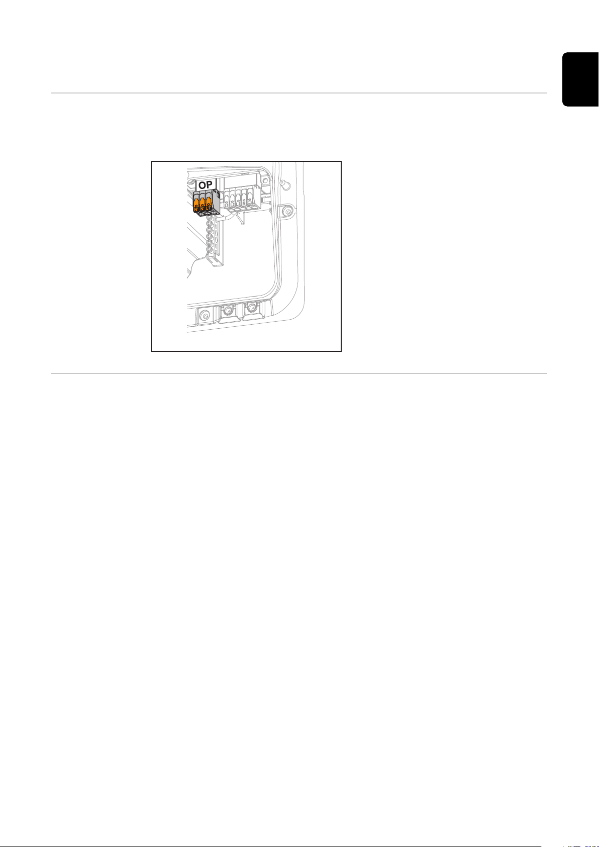
With the PV Point, in the event of a
failure of the public grid, 1‑phase electrical devices can be connected to the
Opportunity Power (OP) terminal and
supplied with a maximum power of
3 kW, if enough power is available from
the PV modules or an optional battery.
In grid-connected operation, the OP
terminal is not supplied with voltage,
therefore the connected loads will not
be supplied with power in this operating mode.
IMPORTANT!
A relay-based network switching setup
is not possible.
Explanation - PV
Point (OP)
The inverter can provide 220 ‑ 240 V at the PV Point. A corresponding configuration must be set up during commissioning.
At 220 ‑ 240 V output voltage, max. 13 A AC continuous current is available.
Example:
230 V *13 A = 2860 W
240 V *13 A = max. 3 kW
In backup power mode, some electrical appliances cannot function properly as
starting currents are too high (for example, fridges and freezers). It is recommended to switch off non-essential loads during backup power mode. Overload capacity of 35% is possible for a duration of 5 seconds, depending on the capacity of
the PV modules and/or the battery at that moment in time.
There is a brief interruption when switching from grid-connected mode to backup
power mode. For this reason, the backup power function cannot be used as an
uninterruptible power supply, for example for computers.
If no energy from the battery or the solar modules is available in backup power
mode, backup power mode ends automatically. If sufficient energy becomes
available from the solar modules once again, backup power mode starts again
automatically.
In the event of excessive consumption, backup power mode is stopped and the
"backup power overload" status code is displayed on the inverter's LED status indicator. The maximum power in backup power mode according to the technical
data must be observed.
41
Page 42

42
Page 43

Backup power variant - Full Backup
43
Page 44

44
Page 45

General
EN
Prerequisites for
backup power
mode
IMPORTANT!
If several backup power variants are available, please note that only one backup
power variant may be installed and configured.
In order to use the inverter's backup power function, the following prerequisites
must be fulfilled:
The inverter must support the backup power variant – Full Backup (see
-
chapter Function overview on page 15).
A battery suitable for backup power use must be installed and configured.
-
Correct cabling of the backup power system in the electrical installation or
-
usage of a switch box from Enwitec (see chapter Components for automatic
Full Backup backup power changeover on page 161 or Circuit diagrams on
page 177).
Mount and configure the Fronius Smart Meter at the feed-in point.
-
Attach a warning notice for the backup power supply (https://www.froni-
-
us.com/en/search-page, item number: 42,0409,0275) on the electrical distributor.
Apply the necessary settings in the "Devices and system components" →
-
"Functions and pins" → "Backup power" menu area and activate backup
power.
Follow the backup power checklist (https://www.fronius.com/en/search-
-
page, item number: 42,0426,0365) step by step and confirm.
Transitioning
from feeding energy into the grid
to backup power
mode
Transitioning
from backup
power mode to
feeding energy
into the grid
The public grid is monitored by the inverter's internal grid and system pro-
1.
tection unit and by the Fronius Smart Meter connected to it.
The public grid fails or specific grid parameters are dropped below or ex-
2.
ceeded.
The inverter carries out the measures necessary according to the country
3.
standard and then switches off.
The inverter starts backup power mode after a checking period.
4.
All loads in the household that are in the backup power circuit are supplied
5.
by the battery and the PV modules. The remaining loads are not supplied
with power and are safely isolated.
The inverter is operating in backup power mode.
1.
The public grid is functioning correctly again.
2.
The Fronius Smart Meter monitors the grid parameters on the public grid
3.
and passes this information to the inverter.
The stability of the returned public grid is determined by checking the meas-
4.
ured values of the Fronius Smart Meter.
The inverter ends backup power mode.
5.
All circuits are reconnected to the public grid and are supplied by the grid.
6.
The inverter can start feeding energy into the grid again after performing the
7.
grid checks required by the relevant standard.
45
Page 46

Backup power
and energy saving mode
Under the following conditions, the battery and the inverter are switched to energy saving mode after a waiting time of 8 - 12 minutes and backup power mode
is ended:
The battery is discharged to the minimum state of charge and no energy is
-
coming from the PV modules.
The inverter is set to energy saving mode (standby mode).
-
If the battery and inverter are in energy saving mode, the system is reactivated
by the following:
Enough energy is available from the PV modules.
-
The public grid is functioning again.
-
The battery is switched off and on.
-
46
Page 47

Cabling variants including backup power circuits
with 3-pin separation e.g. Austria or Australia
Functions
Transitioning
from feeding energy into the grid
to backup power
mode
Measuring and transferring the required parameters for energy management
-
and Solar.web by the Fronius Smart Meter.
Disconnecting from the public grid to enable operation in backup power
-
mode if the grid parameters are outside the country-specific standards.
Reconnecting to the public grid when the grid parameters are within the lim-
-
its specified by the country-specific standards.
Option of having a separate backup power circuit or several backup power
-
circuits that are supplied even during failure of the public grid. The total load
of the backup power circuits must not exceed the nominal output of the inverter. Furthermore, the performance of the connected battery must also be
considered.
The public grid is monitored by the inverter's internal grid and system pro-
1.
tection unit and by the Fronius Smart Meter connected to it.
Failure of the public grid.
2.
The inverter carries out the necessary measures according to the country
3.
standard and then switches off.
Contactors K1 and K2 drop out. This disconnects the backup power circuits
and the inverter from the rest of the home network and from the public grid,
as the main contacts of the contactors K1 and K2 3-pin open. The inverter
activates relay K3, which interrupts the supply to contactors K1 and K2. This
prevents unintentional activation of contactors K1 and K2 and thus a grid
connection when voltage is restored in the grid. The NC auxiliary contacts of
contactors K1 and K2 send feedback to the inverter that the contactors are
open (a condition for starting backup power mode).
The NO contact of relay K3 gives additional feedback to the inverter on
4.
whether the locking was successfully performed by relay K3.
The inverter decides based on the contactors' feedback as well as the meas-
5.
urements on the inverter terminals and the Smart Meter that backup power
mode can be started.
After all the required activation tests have been carried out, the inverter
6.
starts backup power mode.
All loads in the backup power circuits are supplied with power. The remaining
7.
loads are not supplied with power and are safely isolated.
EN
Transitioning
from backup
power mode to
feeding energy
into the grid
The inverter is operating in backup power mode. The contactors K1 and K2 to
1.
the public grid are open.
Public grid available again.
2.
The Fronius Smart Meter monitors the grid parameters on the public grid
3.
and passes this information to the inverter.
The stability of the returned public grid is determined by checking the meas-
4.
ured values of the Fronius Smart Meter.
The inverter ends backup power mode and disconnects the outputs.
5.
The inverter deactivates K3. The contactors K1 and K2 are reactivated.
6.
All circuits are reconnected to the public grid and are supplied by the grid.
7.
The inverter does not feed anything into the grid at this time.
The inverter can start feeding energy into the grid again after performing the
8.
grid checks required by the relevant standard.
47
Page 48

All-pin separation cabling variant e.g. Germany,
France
Functions
Transitioning
from feeding energy into the grid
to backup power
mode
Measuring and transferring the required parameters for energy management
-
and Solar.web by the Fronius Smart Meter.
Disconnecting from the public grid to enable operation in backup power
-
mode if the grid parameters are outside the country-specific standards.
Reconnecting to the public grid when the grid parameters are within the lim-
-
its specified by the country-specific standards.
Establishing a proper ground connection for backup power mode to ensure
-
the protection devices function correctly.
Option of having a separate backup power circuit or several backup power
-
circuits that are supplied even during failure of the public grid. The total load
of the backup power circuits must not exceed the nominal output of the inverter. Furthermore, the performance of the connected battery must also be
considered.
The public grid is monitored by the inverter's internal grid and system pro-
1.
tection unit and by the Fronius Smart Meter connected to it.
Failure of the public grid.
2.
The inverter carries out the necessary measures according to the country
3.
standard and then switches off.
Contactors K1, K2, K4 and K5 drop out. This disconnects the backup power
circuits and the inverter from the rest of the home network and from the
public grid, as the main contacts of the contactors K1 and K2 all-pin open.
The NC auxiliary contacts of contactors K1 and K2 send feedback to the inverter that the contactors are open (a condition for starting backup power
mode).
The NC main contacts of contactors K4 and K5 are closed, establishing a
4.
connection between the neutral conductor and the ground conductor. The
two other NC main contacts of contactors K4 and K5 give feedback to the
inverter that the ground connection has been established correctly (a condition for starting backup power mode).
The inverter activates relay K3, which interrupts the supply to contactors K1,
5.
K2, K4 and K5. This prevents unintentional activation of contactors K1, K2,
K4 and K5 and thus a grid connection when voltage is restored in the grid.
The NO contact of relay K3 gives additional feedback to the inverter on
6.
whether the locking was successfully performed by relay K3.
The inverter decides based on the contactors' feedback as well as the meas-
7.
urements on the inverter terminals and the Smart Meter that backup power
mode can be started.
After all the required activation tests have been carried out, the inverter
8.
starts backup power mode.
All loads in the backup power circuits are supplied with power. The remaining
9.
loads are not supplied with power and are safely isolated.
48
Page 49

Transitioning
from backup
power mode to
feeding energy
into the grid
The inverter is operating in backup power mode. The contactors K1 and K2 to
1.
the public grid are open.
Public grid available again.
2.
The Fronius Smart Meter monitors the grid parameters on the public grid
3.
and passes this information to the inverter.
The stability of the returned public grid is determined by checking the meas-
4.
ured values of the Fronius Smart Meter.
The inverter ends backup power mode and disconnects the outputs.
5.
The inverter deactivates K3. Power is restored to contactors K1, K2, K4 and
6.
K5.
All circuits are reconnected to the public grid and are supplied by the grid.
7.
The inverter does not feed anything into the grid at this time.
The inverter can start feeding energy into the grid again after performing the
8.
grid checks required by the relevant standard.
EN
49
Page 50

All-pin separation cabling variant, Italy
Functions
Transitioning
from feeding energy into the grid
to backup power
mode
Measuring and transferring the required parameters for energy management
-
and Solar.web by the Fronius Smart Meter.
Monitoring of the voltage and frequency grid parameters by the inverter.
-
Disconnecting from the public grid to enable operation in backup power
-
mode if the grid parameters are outside the country-specific standards.
Reconnecting to the public grid when the grid parameters are within the lim-
-
its specified by the country-specific standards.
Establishing a correct ground connection for backup power mode.
-
Option of having a separate backup power circuit or several backup power
-
circuits that are supplied even during failure of the public grid. The total load
of the backup power circuits must not exceed the nominal output of the inverter. Furthermore, the performance of the connected battery must also be
considered.
The public grid is monitored by the inverter's internal grid and system pro-
1.
tection unit and by an external grid and system protection unit.
Failure of the public grid
2.
The inverter carries out the measures necessary according to the country
3.
standard and then switches off.
The external grid and system protection unit opens contactors K1 and K2 for
4.
grid monitoring. This disconnects the backup power circuits and the inverter
from the rest of the home network and from the public grid, as the main contacts of the contactors K1 and K2 all-pin open. To ensure that the public grid
has definitely been disconnected, the NC auxiliary contacts of contactor K1
give feedback to the external grid and system protection unit.
The NC main contacts of contactors K4 and K5 are closed, establishing a
5.
connection between the neutral conductor and the ground conductor. The
two other NC main contacts of contactors K4 and K5 give feedback to the
inverter that the ground connection has been established correctly.
The inverter activates relay K3, which activates the remote input of the ex-
6.
ternal grid and system protection unit via an NC contact. This prevents a
connection to the public grid when voltage is restored in the grid.
The NO contact of relay K3 gives additional feedback to the inverter on
7.
whether the locking was successfully performed by relay K3.
The inverter decides based on the contactor's feedback as well as the meas-
8.
urement on the inverter terminals and the Smart Meter that the emergency
power mode can be activated.
The inverter starts backup power mode after a defined checking period.
9.
All loads in the backup power circuits are supplied with power. The remaining
10.
loads are not supplied with power and are safely isolated.
50
Page 51

Transitioning
from backup
power mode to
feeding energy
into the grid
The inverter is operating in backup power mode. The contactors K1 and K2 to
1.
the public grid are open.
Public grid available again.
2.
The Fronius Smart Meter monitors the grid parameters on the public grid
3.
and passes this information to the inverter.
The stability of the returned public grid is determined by checking the meas-
4.
ured values of the Fronius Smart Meter.
On the basis of adjustments that have been carried out, the inverter ends
5.
backup power mode and disconnects the outputs.
The inverter deactivates K3. Power is restored to contactors K1, K2, K4 and
6.
K5.
All circuits are reconnected to the public grid and are supplied by the grid.
7.
The inverter does not feed anything into the grid at this time.
The inverter can start feeding energy into the grid again after performing the
8.
grid checks required by the relevant standard.
EN
51
Page 52

52
Page 53

Installation
53
Page 54

54
Page 55

General
EN
Quick-lock system
A quick-lock system (3) is used to
mount the connection area cover and
front cover. The system is opened and
closed with a half-rotation (180°) of
the captive screw (1) into the quicklock spring (2).
The system is independent of torque.
NOTE!
Danger when using a drill driver.
This may result in the destruction of the quick-lock system due to overtorque.
Use a screwdriver (TX20).
▶
Do not turn the screws more than 180°.
▶
Warning notices
on the device
Technical data, warning notices and safety symbols are affixed to the inverter.
These warning notices and safety symbols must not be removed or painted over.
They warn against incorrect operation which can lead to serious injury and damage.
A 4-digit number (coded production date) is printed on the rating plate at the
very bottom, from which the production date can be calculated.
If you subtract the value 11 from the first two digits, you get the production year.
The last two digits stand for the calendar week in which the device was produced.
Example:
Value on rating plate = 3206
55
Page 56
32 - 11 = 21 → Production year 2021
06 = Calendar week 06
Symbols on the rating plate:
CE mark – confirms compliance with applicable EU directives and
regulations.
UKCA mark – confirms compliance with applicable UK directives and
regulations.
WEEE mark – waste electrical and electronic equipment must be
collected separately and recycled in an environmentally sound manner
in accordance with the European Directive and national law.
RCM mark – tested in accordance with the requirements of Australia
and New Zealand.
ICASA mark – tested in accordance with the requirements of the
Independent Communications Authority of South Africa.
CMIM mark – tested in accordance with IMANOR requirements for
import regulations and compliance with Moroccan standards.
Safety symbols:
Risk of serious injury and property damage due to incorrect operation.
System component compatibility
Do not use the functions described here until you have fully read and
understood the following documents:
These Operating Instructions.
-
All the Operating Instructions for the photovoltaic system compon-
-
ents, especially the safety rules.
Dangerous electrical voltage.
Allow the capacitors of the inverter to discharge (2 minutes).
Warning notice text:
WARNING!
An electric shock can be fatal. Before opening the device, it must be disconnected and de-energized at the input and output.
All installed components in the photovoltaic system must be compatible and
have the necessary configuration options. The installed components must not restrict or negatively influence the functioning of the photovoltaic system.
NOTE!
56
Risk due to components in the photovoltaic system that are not compatible
and/or have limited compatibility.
Incompatible components may limit and/or negatively affect the operation
and/or functioning of the photovoltaic system.
Only install components recommended by the manufacturer in the photovol-
▶
taic system.
Before installation, check the compatibility of components not expressly re-
▶
commended with the manufacturer.
Page 57

Installation location and position
≥ 200 mm
(≥ 7.87 inch)
≥ 200 mm
(≥ 7.87 inch)
≥ 445 mm
(≥ 17.52 inch)
≥ 250 mm
(≥ 9.84 inch)
≥ 225 mm
(≥ 8.86 inch)
≥ 275 mm
(≥ 10.83 inch)
≥ 150 mm
(≥ 5.91 inch)
≥ 100 mm
(≥ 3.94 inch)
-25°C - +60°C
0 - 100%
EN
Choosing the
location of the
inverter
Please note the following criteria when choosing a location for the inverter:
Only install on a solid, non-flam-
mable surface.
Max. ambient temperatures:
-25 °C – +60 °C
Relative humidity:
0-100%
If the inverter is installed in a switch
cabinet or similar enclosed space,
ensure sufficient heat dissipation
with forced-air ventilation.
For detailed information on the dimensions of the inverter, see chapter
Fronius Symo GEN24 6 - 10 kW on
page 195.
When installing the inverter on the outer walls of cattle sheds, it is important
to maintain a minimum clearance of 2 m between the inverter and the ventilation and building openings on all sides.
The following substrates are permissible for installation:
Walls (corrugated metal walls [mounting rails], brick walls, concrete walls,
-
or other non-flammable surfaces sufficiently capable of bearing loads)
Mast or support (installed using mounting rails, behind the PV modules
-
directly on the PV mounting system)
Flat roofs (if installing on a film roof, make sure that the films comply
-
with the fire protection requirements and are not highly flammable. En-
sure compliance with the national provisions.)
Covered car park roofs (no overhead installation)
-
The inverter is suitable for indoor installation.
The inverter is suitable for outdoor installation.
Due to its protection class IP 66, the inverter is insensitive to
water jets from all directions and can also be used in humid environments.
In order to minimise the heating up of the inverter, do not expose it to direct insolation.
The inverter should be installed in a protected location, for example, below the PV modules or under an overhanging roof.
57
Page 58

The inverter must not be installed or used at altitudes above
4000 m.
Do not install the inverter in:
Areas where it may be exposed to ammonia, corrosive
-
gases, acids or salts (e.g. fertiliser storage areas, vent openings for livestock stables, chemical plants, tanneries, etc.)
During certain operating phases the inverter may produce a
slight noise. For this reason it should not be installed in an occupied living area.
Do not install the inverter in:
Areas where there is an increased risk of accidents from
-
farm animals (horses, cattle, sheep, pigs, etc.)
Stables or adjoining areas
-
Storage areas for hay, straw, chaff, animal feed, fertilizers,
-
etc.
The inverter is designed to be dustproof (IP 66). In areas of high
dust accumulation, dust deposits may collect on the cooling
surfaces, and thus impair the thermal performance. Regular
cleaning is required in this case, see chapter Operation in dusty
environments on page 157. We therefore recommend not in-
stalling the device in areas and environments with high dust accumulation.
Choosing the
location of thirdparty batteries
Installation position of inverter
Do not install the inverter in:
Greenhouses
-
Storage or processing areas for fruit, vegetables or viticul-
-
ture products
Areas used in the preparation of grain, green fodder or an-
-
imal feeds
IMPORTANT!
Refer to the manufacturer's documents for the suitable location for third-party
batteries.
The inverter is suitable for vertical installation on a vertical wall
or column.
58
Page 59

The inverter is suitable for a horizontal installation position.
The inverter is suitable for installation on a sloping surface.
Do not install the inverter on a sloping surface with its connection sockets at the top.
Do not install the inverter at an angle on a vertical wall or
column.
Do not install the inverter horizontally on a vertical wall or pillar.
EN
Do not install the inverter on a vertical wall or pillar with its connection sockets facing upwards.
Do not install the inverter overhanging with the connection
sockets at the top.
Do not install the inverter overhanging with the connection
sockets at the bottom.
Do not install the inverter on the ceiling.
59
Page 60
Install the mounting bracket and hang up the inverter
Selecting the fixing material
Properties of the
mounting bracket
Use the corresponding fixing materials depending on the subsurface and observe
the screw dimension recommendations for the mounting bracket.
The installer is responsible for selecting the correct type of fixing.
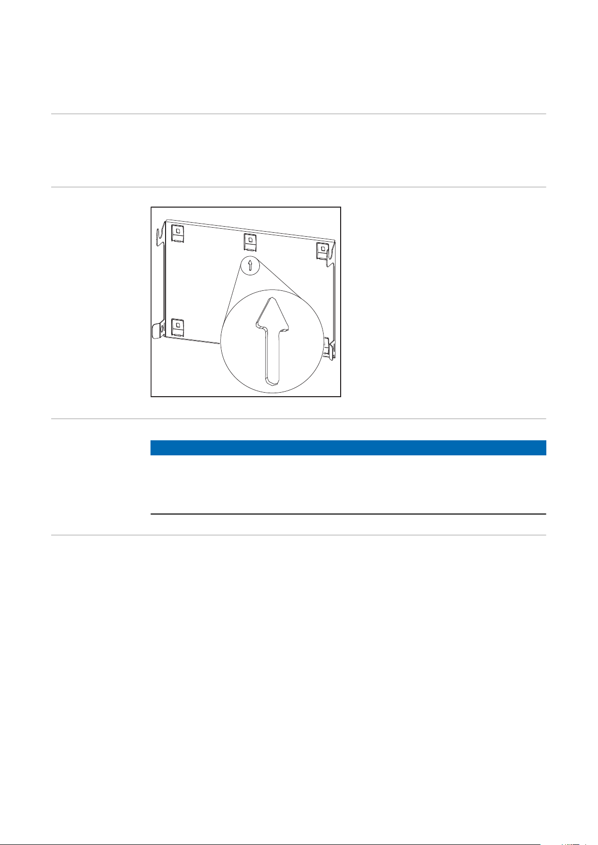
The mounting bracket (illustration) is
also used as the gauge.
The pre-drilled holes on the mounting
bracket are intended for screws with a
thread diameter of 6 - 8 mm (0.24 -
0.32 inches).
Unevenness on the installation surface
(for example, coarse-grained plaster) is
largely counterbalanced by the mounting bracket.
Do not deform
the mounting
bracket
Fitting the
mounting bracket to a wall
NOTE!
When fitting the mounting bracket to the wall or column, ensure that the
mounting bracket does not become deformed.
A deformed mounting bracket may make it difficult to clip/swivel the inverter into position.
IMPORTANT!
When installing the mounting bracket, make sure that it is installed with the arrow pointing upwards.
60
Page 61

1 2
3
EN
Installing the
mounting bracket on a mast or
beam
When installing the inverter on a mast
or beam, Fronius recommends using
the "Pole clamp" (order no. SZ
2584.000) mounting kit from Rittal
GmbH.
The "Pole clamp" kit covers the following dimensions:
Rectangular mast or beam with a
-
side length of 50-150 mm
(1.97-5.91 inches)
Round mast or beam with a dia-
-
meter of 40-190 mm
(1.57-7.48 inches)
61
Page 62

Attaching the
mounting bracket to mounting
rails
IMPORTANT!
The mounting bracket must be affixed
at a minimum of four points.
Attaching the inverter to the
mounting bracket
There are integrated grips on the side
of the inverter which facilitate lifting/
attaching.
1
Clip the inverter into the mounting
bracket from above. The connections
must point downwards.
Push the lower part of the inverter into
the snap-in tabs of the mounting
bracket until the inverter audibly clicks
into place on both sides.
62
Check that the inverter is correctly positioned on both sides.
Page 63

Prerequisites for connecting the inverter
EN
Permissible
cables for the
Cables with the following design can be connected to the terminals of the inverter:
electrical connection
Copper: round, solid
-
Copper: round, fine-stranded, up to conductor class 4
-
Grid connections with push-in terminal*
Select a sufficiently large cable cross section based on the actual device output.
Number of
pins
5
Solid Multi-stranded Fine-stranded
2.5 - 10 mm
2
2.5 - 10 mm
2
2.5 - 10 mm
Fine-stranded with ferrules‐
with/without collar
2
Grid connections backup power with push-in terminal*
Select a sufficiently large cable cross section based on the actual device output.
Number of
pins
3
Solid Multi-stranded Fine-stranded
1.5 - 10 mm
2
1.5 - 10 mm
2
1.5 - 10 mm
Fine-stranded with ferrules‐
with/without collar
2
2.5 - 6 mm
1.5 - 6 mm
2
2
PV/BAT connections with push-in terminal**
Select a sufficiently large cable cross section based on the actual device output.
Number of
pins
2 x 4
Solid Multi-stranded Fine-stranded
4 - 10 mm
2
4 - 10 mm
2
4 - 10 mm
Fine-stranded with ferrules‐
with/without collar
2
Ground electrode terminal
Select a sufficiently large cable cross section based on the actual device output.
Number of
pins
2
4
Solid Multi-stranded Fine-stranded
2.5 - 16 mm
2.5 - 10 mm
2
2
2.5 - 16 mm
2.5 - 10 mm
2
2
2.5 - 16 mm
2.5 - 10 mm
Fine-stranded with ferrules‐
with/without collar
2
2
2.5 - 16 mm
2.5 - 10 mm
* According to product standard IEC 62109, the ground conductor must
correspond to the phase cross-section for phase cross-sections ≤16 mm²;
for phase cross-sections >16 mm², it must correspond to at least 16 mm².
** The cable cross section must be dimensioned in accordance with the in-
stallation situation and the specifications of the battery manufacturer.
4 - 6 mm
2
2
2
Permitted cables
for the data
communication
connection
Cables with the following design can be connected to the terminals of the inverter:
63
Page 64

Copper: round, solid
-
Copper: round, fine-stranded
-
IMPORTANT!
Connect the individual conductors to an appropriate ferrule if several individual
conductors are connected to one input of the push-in terminals.
WSD connections with push-in terminal
Dis-
tance
max.
100 m
109 yd
Strip-
ping
length
10 mm
0.39 inch
Solid
0.14 -
1.5 mm
2
AWG 26 - 16
Fine-stran-
1.5 mm
AWG 26 - 16
Modbus connections with push-in terminal
Dis-
tance
max.
300 m
328 yd
Strip-
ping
length
10 mm
0.39 inch
Solid
0.14 -
1.5 mm
2
AWG 26 - 16
Fine-stran-
1.5 mm
AWG 26 - 16
IO connections with push-in terminal
Dis-
tance
max.
Strip-
ping
length
Solid
Fine-stran-
ded
0.14 -
ded
0.14 -
ded
Fine-stran-
ded with fer-
rules with
collar
2
0.14 - 1 mm
AWG 26 - 18
Fine-stran-
ded with fer-
rules with
collar
2
0.14 - 1 mm
AWG 26 - 18
Fine-stran-
ded with fer-
rules with
collar
Fine-stran-
ded with fer-
rules without
2
1.5 mm
AWG 26 - 16
Fine-stran-
ded with fer-
rules without
2
1.5 mm
AWG 26 - 16
Fine-stran-
ded with fer-
rules without
collar
0.14 -
collar
0.14 -
collar
2
2
Cable re-
commenda-
tion
min. CAT 5
UTP (un-
shielded
twisted pair)
Cable re-
commenda-
tion
min. CAT 5
STP (shiel-
ded twisted
pair)
Cable re-
commenda-
tion
30 m
32 yd
10 mm
0.39 inch
0.14 -
1.5 mm
2
AWG 26 - 16
0.14 -
1.5 mm
2
AWG 26 - 16
0.14 - 1 mm
AWG 26 - 18
2
1.5 mm
AWG 26 - 16
0.14 -
2
ductor pos-
sible
Single con-
LAN connections
Fronius recommends at least CAT 5 STP (Shielded Twisted Pair) cables and a maximum distance of
100 m (109 yd).
Cross section of
the AC cable
For a standard M32 metric screw joint with a reducer:
Cable diameter from 7 - 15 mm
When using an M32 metric screw joint (reducer removed):
cable diameter from 11-21 mm
(with a cable diameter of less than 11 mm, the strain-relief force is reduced from
100 N to a maximum of 80 N)
64
Page 65

With cable diameters greater than 21 mm, the M32 screw joint must be replaced
by an M32 screw joint with a larger clamping area – item number: 42,0407,0780
– strain-relief device M32 x 1.5 KB 18–25.
EN
Cross section of
the DC cable
Maximum alternating current
fuse protection
Cable diameter for the strain-relief device: max. 9 mm.
Cable diameter for the connection to the push-in terminal: max. 6 mm
IMPORTANT!
For double-insulated cables with a cable diameter over 6 mm, the external insulation layer must be removed to connect to the push-in terminal.
NOTE!
The national regulations of the grid
operator or other factors may require
a residual current circuit breaker in
the AC connection lead.
For this situation, a type A residual
current circuit breaker is generally adequate. Nevertheless, false alarms can
be triggered for the type A residualcurrent circuit breaker in individual
cases and depending on local conditions. For this reason, in accordance
with national legislation, Fronius recommends that a residual-current circuit breaker with a tripping current of
at least 100 mA suitable for frequency
converters be used.
IMPORTANT!
As a maximum, the inverter can be
used with an automatic circuit breaker
C 32 A.
Recom-
PhasesAC out-
Inverter
Fronius Symo GEN24 6 kW 3 6000 W C 32 A C 16 A
Fronius Symo GEN24 8 kW 3 8000 W C 32 A C 25 A
Fronius Symo GEN24 10 kW 3 10,000 W C 32 A C 32 A
put
Maximum
fuse rating
mended
fuse rating
65
Page 66

Connecting the inverter to the public grid (AC
side)
Safety
WARNING!
Danger due to incorrect operation and incorrectly performed work.
This can result in serious injury and damage to property.
Read the Installation and Operating Instructions before installing and com-
▶
missioning the equipment.
Only qualified personnel are authorised to commission your inverter and only
▶
within the scope of the respective technical regulations.
WARNING!
Danger due to grid voltage and DC voltage from solar modules that are exposed
to light.
An electric shock can be fatal.
Prior to any connection work, disconnect the inverter on the AC side and the
▶
DC side.
Only an authorised electrical engineer is permitted to connect this equip-
▶
ment to the public grid.
WARNING!
Danger due to damaged and/or contaminated terminals.
This can result in serious injury and damage to property.
Before making any connections, check the terminals for damage and con-
▶
tamination.
Remove contamination in the de-energized state.
▶
Have defective terminals repaired by an authorised specialist.
▶
Connecting the
inverter to the
public grid (AC
side)
66
NOTE!
The neutral conductor must be connected in order to operate the inverter.
It is not possible to operate the inverter in unearthed grids, such as IT grids (insulated grids without ground conductor).
Make sure that the grid's neutral conductor is grounded.
▶
IMPORTANT!
The ground conductor of the AC cable must be laid in such a way that it is the
last to be disconnected in the event that the strain-relief device should fail.
This can be ensured by making it somewhat longer and by laying it in a loop.
Page 67

1
Turn off the automatic circuit breaker.
EN
2
Make sure that the DC disconnector is
in the "Off" switch setting.
Loosen the five screws of the connection area cover by rotating them 180°
to the left using a screwdriver (TX20).
Remove the connection area cover
from the device.
3
Press the lock on the back of the terminal and remove the AC terminal.
Route the mains cable from below
through the strain-relief device located
on the right side and the ferrite core.
IMPORTANT!
The ground conductor must not be
routed through the ferrite core and
must be connected with a loop so that
if the strain-relief device fails, the
ground conductor is disconnected last.
For more information on the strain-relief device, see chapter Cross section
of the AC cable on page 64.
4
Strip the insulation of the single conductors by 12 mm.
The cable cross section must be selected in accordance with the instructions
in Permissible cables for the electric-
al connection from page 63.
Lift to open the terminal's operating
lever and insert the stripped single
conductor into the slot provided as far
as it will go. Then close the operating
lever until it engages.
IMPORTANT!
Only one conductor may be connected
to each pin. The AC cables can be connected to the AC terminal without ferrules.
67
Page 68

5
L1 Phase conductor
L2 Phase conductor
L3 Phase conductor
N Neutral conductor
PE Ground conductor
6
Insert the AC terminal into the AC slot
until it engages. Fasten the cap nut of
the strain-relief device with a torque of
6 ‑ 7 Nm.
68
Page 69

Connecting solar module strings to the inverter
EN
General comments regarding
PV modules
To enable suitable PV modules to be chosen and to use the inverter as efficiently
as possible, it is important to bear the following points in mind:
If insolation is constant and the temperature is falling, the open-circuit
-
voltage of the PV modules will increase. The open-circuit voltage must not
exceed the maximum permissible system voltage. If the open-circuit voltage
exceeds the specified values, the inverter will be destroyed and all warranty
claims will be forfeited.
The temperature coefficients on the data sheet of the PV modules must be
-
observed.
Exact values for sizing the PV modules can be obtained using suitable calcu-
-
lation tools, such as the Fronius Solar.creator.
IMPORTANT!
Before connecting up the PV modules, check that the voltage for the PV modules specified by the manufacturer corresponds to the actual measured voltage.
IMPORTANT!
The PV modules connected to the inverter must comply with the IEC
61730 Class A standard.
IMPORTANT!
Solar module strings must not be
earthed.
Safety
WARNING!
Danger due to incorrect operation and incorrectly performed work.
This can result in serious injury and damage to property.
Commissioning as well as maintenance and service work in the power module
▶
of the inverter must only be carried out by service personnel trained by
Fronius and only within the scope of the respective technical regulations.
Read the Installation and Operating Instructions before installing and com-
▶
missioning the equipment.
WARNING!
Danger due to grid voltage and DC voltage from solar modules that are exposed
to light.
This can result in serious injury and damage to property.
Ensure that the AC and DC side of the inverter are de-energised before car-
▶
rying out any connection, maintenance or service tasks.
Only an authorised electrical engineer is permitted to connect this equip-
▶
ment to the public grid.
69
Page 70

WARNING!
Danger due to damaged and/or contaminated terminals.
This can result in serious injury and damage to property.
Before making any connections, check the terminals for damage and con-
▶
tamination.
Remove contamination in the de-energized state.
▶
Have defective terminals repaired by an authorised specialist.
▶
Module array general information
Module array
configuration
6 - 10 kW
2 independent PV inputs (PV 1 and PV 2) are available. These can be connected
to a different number of modules.
When using for the first time, set up the module array according to the respective configuration (also possible later in the “System configuration” menu under
the “Components” menu item).
IMPORTANT!
The installation must be carried out in accordance with the nationally applicable
standards and directives. If the Arc Fault Circuit Interrupter integrated in the inverter is used for the requirement according to IEC 63027 for arc detection, the
solar module strings must not be combined in front of the inverter.
Module array settings:
PV 1: ON
PV 2: OFF
Current less than or equal to 25 A (I
Combined solar module strings with total current less than or equal to 25 A (I
dcmax
dcmax
).
).
Module array settings:
PV 1: ON
PV 2: OFF
70
Page 71

Combined solar module strings with total current greater than 25 A (I
dcmax
).
Module array settings:
PV 1: ON
PV 2: OFF
PV 1 + PV 2 (connected in parallel):
ON
IMPORTANT!
The maximum current load of a single
terminal is 25 A. PV‑connection strings
with a total current of more than 25 A
must be split between both PV inputs
upstream of the terminals (I
SC max
≤ 60 A). The plug connection for splitting the total current must be sufficiently dimensioned, suitable and correctly installed. Splitting the current
by bridging from PV 1 to PV 2 at the
terminal is not permitted.
Module array settings:
PV 1: ON
PV 2: ON
EN
Connecting the
solar module
strings to the inverter
PV 1 less than or equal to 40 A (I
PV 2 less than or equal to 20 A (I
1
SC PV1
SC PV2
)
)
71
Page 72

+ -
1
2
2
1
2
+ -
+ -
2
1
PUSH
2
Push the DC cables through the DC
bushings by hand.
IMPORTANT!
Before stripping the insulation, push
the cables through the DC bushings to
prevent individual wires being bent or
broken.
3
4
72
Page 73

5
+
-
PV1+PV1+PV2+BAT
+
PV2
-
BAT
-
PV1-PV1
-
Select the cable cross section in accordance with the instructions in Per-
missible cables for the electrical con-
EN
nection from page 63.
Strip the insulation of the single conductors by 12 mm. Lift to open the terminal's operating lever and insert the
stripped single conductor into the slot
provided, in each case as far as it will
go. Then close the operating lever until
it engages.
WARNING!
Danger due to individual conductors in
the terminal that are loose and/or improperly connected.
This can result in serious injury and
damage to property.
Only connect one single conductor
▶
in the slot provided for each terminal.
Check that the single conductor is
▶
held securely in the terminal.
Ensure that all of the single con-
▶
ductor is within the terminal and
that no individual wires are sticking
out of the terminal.
6
73
Page 74

7
1
+ / -
+
-
3
TX 20
1,3 - 1,5 Nm
+ -
1
2
"click"
8
9
Use a suitable measuring instrument
to check the voltage and polarity of
the DC cabling. Remove both DC terminals from the slots.
CAUTION!
Danger due to polarity reversal at the
terminals.
This may result in severe damage to
the inverter.
Use a suitable measuring instru-
▶
ment to check the polarity of the
DC cabling.
Use a suitable measuring instru-
▶
ment to check the voltage (max.
1000 VDC)
Insert the DC terminals into the respective slot until they engage. Fasten
the screws of the strain-relief device to
the housing using a screwdriver (TX20)
and a torque of 1.3-1.5 Nm.
74
NOTE!
Risk due to overtorque on the strainrelief device.
This may result in damage to the
strain-relief device.
Do not use a drill driver.
▶
Page 75

Connecting the battery to the inverter
EN
Safety
WARNING!
Danger due to incorrect operation and incorrectly performed work.
This can result in serious injury and damage to property.
Commissioning as well as maintenance and service work on the inverter and
▶
battery must only be carried out by service personnel trained by the respective inverter or battery manufacturer and only within the scope of the respective technical regulations.
Read the Installation and Operating Instructions provided by the respective
▶
manufacturer before installing and commissioning the equipment.
WARNING!
Danger due to grid voltage and DC voltage from solar modules that are exposed
to light and from batteries.
This can result in serious injury and damage to property.
Ensure that the AC and DC side of the inverter and the battery are de-ener-
▶
gised before carrying out any connection, maintenance or service tasks.
Only an authorised electrical engineer is permitted to connect this equip-
▶
ment to the public grid.
WARNING!
Connecting the
battery on the
DC side
Danger due to damaged and/or contaminated terminals.
This can result in serious injury and damage to property.
Before making any connections, check the terminals for damage and con-
▶
tamination.
Remove contamination in the de-energized state.
▶
Have defective terminals repaired by an authorised specialist.
▶
CAUTION!
Danger due to operation of the battery above the permissible altitude as specified by the manufacturer.
Operating the battery above the permissible altitude can result in restricted operation, failure of the operation, and unsafe states of the battery.
Adhere to the manufacturer's instructions regarding the permissible altitude.
▶
Operate the battery only at the altitude specified by the manufacturer.
▶
IMPORTANT!
Prior to installing a battery, ensure that the battery is switched off. The max. DC
cable length for the installation of external batteries must be taken into account
according to the manufacturer's specifications, see chapter Suitable batteries on
page 27.
75
Page 76

1
2
BAT PE
BAT+
BAT-
3*
1
1
2
BAT+
BAT-
Manually push the battery cables
through the DC bushings.
* The battery ground conductor must
be connected externally (e.g. switch
cabinet). When connecting an LG
RESU FLEX battery, the battery
ground conductor can be connected in
the inverter (see chapter Connecting
the LG RESU FLEX ground conductor
on page 79. Observe the minimum
cross section of the ground conductor
to the battery.
IMPORTANT!
Before stripping the insulation, push
the cables through the DC bushings to
prevent individual wires being bent or
broken.
2
76
Page 77

3
1
PUSH
2
BAT+
BAT-
2
Select the cable cross section in accordance with the instructions in Per-
missible cables for the electrical connection from page 63.
Strip the insulation of the single conductors by 12 mm. Lift to open the terminal's operating lever and insert the
stripped single conductor into the slot
provided, in each case as far as it will
go. Then close the operating lever until
it engages.
WARNING!
Danger due to individual conductors in
the terminal that are loose and/or improperly connected.
This can result in serious injury and
damage to property.
Only connect one single conductor
▶
in the slot provided for each terminal.
Check that the single conductor is
▶
held securely in the terminal.
Ensure that all of the single con-
▶
ductor is within the terminal and
that no individual wire strands are
sticking out of the terminal.
EN
4
77
Page 78

5
Risk due to overvoltage when using
other slots on the terminal.
This may result in damage to the battery and/or the PV modules due to discharge.
▶
CAUTION!
Only use the slots marked BAT for
battery connection.
6
Danger due to polarity reversal at the
terminals.
Serious substantive damage to the PV
system may result.
▶
▶
7
Insert the DC terminals into the respective slot until they engage.
CAUTION!
Use a suitable measuring instrument to check the polarity of the
DC cabling when the battery is
switched on.
The maximum voltage for the battery input must not be exceeded
(see Technical data on page 164).
78
Page 79

8
IMPORTANT!
Information for connection on the battery side can be found in the Installation
Instructions from the relevant manufacturer.
Fasten the screws of the cable guide to
the housing using a screwdriver (TX20)
and a torque of 1.3-1.5 Nm.
NOTE!
Risk due to overtorque on the strainrelief device.
This may result in damage to the
strain-relief device.
Do not use a drill driver.
▶
EN
Connecting the
LG RESU FLEX
ground conductor
1
2
Route the battery ground conductor in
the integrated cable duct of the connection area divider into the AC connection area.
Fasten the battery ground conductor
to the second input of the ground
electrode terminal from above using a
screwdriver (TX20) and a torque of
1.8-2 Nm.
IMPORTANT!
Information for connection on the battery side can be found in the Installation
Instructions from the relevant manufacturer.
79
Page 80

Connecting backup power - PV Point (OP)
Safety
WARNING!
Danger from incorrect installation, commissioning, operation or incorrect use.
This can result in serious injury and damage to property.
Only trained and qualified personnel are authorised to install and commis-
▶
sion the system, and only within the scope of the technical regulations.
The Installation and Operating Instructions must be read carefully prior to
▶
use.
If anything is unclear, contact your vendor immediately.
▶
WARNING!
Danger due to damaged and/or contaminated terminals.
This can result in serious injury and damage to property.
Before making any connections, check the terminals for damage and con-
▶
tamination.
Remove contamination in the de-energized state.
▶
Have defective terminals repaired by an authorised specialist.
▶
NOTE!
The continuous supply via the PV Point depends on the available PV power.
If the solar modules are not supplying enough power, interruptions may occur.
Do not connect any loads that require an interruption-free supply.
▶
Installation
IMPORTANT!
The valid national laws, standards and provisions, as well as the specifications of
the relevant grid operator are to be taken into account and applied.
It is highly recommended that the specific installation be agreed with the grid
operator and explicitly approved by this operator. This obligation applies to system constructors in particular (e.g. installers).
NOTE!
All loads that have to be supplied via the OP terminal must be protected by
means of a residual-current circuit breaker.
In order to ensure the residual-current circuit breaker operates properly, a connection must be established between the neutral conductor N´ (OP) and earth.
For the Circuit Diagram recommended by Fronius, see Circuit Diagram - PV
Point (OP) on page 179.
80
Page 81

1
Switch off the automatic circuit breaker and DC disconnector.
EN
2
CAUTION!
Danger from faulty or incorrect holes.
This may lead to injuries to the eyes and hands as a result of flying debris and
sharp edges, as well as damage to the inverter.
When drilling, wear suitable protective goggles.
▶
Only use a step drill when drilling.
▶
Ensure that nothing is damaged inside the device (for example connection
▶
block).
Adapt the diameter of the hole to match the corresponding connection.
▶
Deburr the holes using a suitable tool.
▶
Remove the drilling residues from the inverter.
▶
Make sure that the DC disconnector is
in the "Off" switch setting.
Loosen the five screws of the connection area cover by rotating them 180°
to the left using a screwdriver (TX20).
Remove the connection area cover
from the device.
81
Page 82

3
Drill out the optional cable guide with
a step drill.
4
Insert the strain-relief device into the
hole and secure to the torque specified
by the manufacturer.
5
Guide the mains cable through the
strain-relief device from below.
Remove the OP terminal.
82
Page 83

6
Strip the insulation of the single conductors by 12 mm.
The cable cross section must be
between 1.5 mm2 and 10 mm2. Lift to
open the terminal's operating lever and
insert the stripped single conductor into the slot provided, all the way up to
the stop. Then close the operating
lever until it engages.
WARNING!
Danger due to individual conductors in
the terminal that are loose and/or improperly connected.
This can result in serious injury and
damage to property.
Only connect one single conductor
▶
in the slot provided for each terminal.
Check that the single conductor is
▶
held securely in the terminal.
Ensure that all of the single con-
▶
ductor is within the terminal and
that no individual wires are sticking
out of the terminal.
EN
7
8
L1´ Phase conductor
N´ Neutral conductor
N´ PEN conductor
IMPORTANT!The PEN conductor
must be produced with ends that are
permanently marked blue, according
to the national provisions, and have a
cross section of 10 mm².
Fasten the ground conductor and PEN
conductor to the ground electrode terminal using a screwdriver (TX20) and a
torque of 1.8-2 Nm.
83
Page 84

9
Insert the OP terminal into the OP slot
until it engages. Tighten the cap nut of
the strain-relief device to the torque
specified by the manufacturer.
84
Page 85

Connecting backup power - Full Backup
EN
Safety
WARNING!
Danger from incorrect installation, commissioning, operation or incorrect use.
This can result in severe personal injury/damage to property.
Only trained and qualified personnel are authorised to install and commis-
▶
sion the system, and only within the scope of the technical regulations.
The Installation and Operating Instructions must be read carefully prior to
▶
use.
If anything is unclear, contact your vendor immediately.
▶
IMPORTANT!
The valid national laws, standards and provisions, as well as the specifications of
the relevant grid operator are to be taken into account and applied.
It is highly recommended to coordinate the concrete examples implemented and
in particular the specific installation with the grid operator to obtain their explicit
approval. This obligation applies to system constructors in particular (e.g. installers).
The examples suggested here show a backup power supply with or without an external protection relay (external grid and system protection unit). Whether an external protection relay must be used or not is the decision of the respective grid
operator.
IMPORTANT!
An uninterruptible power supply (UPS) may only be used to supply individual
loads (e.g. computers). Feeding into the power supply of the house network is not
permitted. The Installation and Operating Instructions must be read carefully
prior to use. If anything is unclear, contact your vendor immediately.
Cabling variants
including backup
power circuits
with 3-pin separation e.g. Austria
or Australia
The examples given in this document (in particular cabling variants and Circuit
Diagrams) are suggestions only. These examples have been carefully developed
and tested. They can therefore be used as a basis for real-life installation. Anyone
following or using these examples does so at their own risk.
IMPORTANT!
The cabling variant required by the grid operator must be clarified with the grid
operator.
Circuit Diagram
The Circuit Diagram for the 3-pin double Fault Ride Through (FRT)-capable separation - e.g. Austria, can be found in the appendix of this document on page
185.
The Circuit Diagram for the 3-pin double separation - e.g. Austria, can be found
in the appendix of this document on page 186.
The Circuit Diagram for the 3-pin single separation - e.g. Australia, can be found
in the appendix of this document on page 187.
Cabling of backup power circuit and non-backup power circuits
If not all the loads in the home need to be supplied in a backup power situation,
the circuits need to be divided into backup power circuits and non-backup power
circuits. The total load of the backup power circuits must not exceed the nominal
output of the inverter.
The backup power circuits and non-backup power circuits must be fused separ-
85
Page 86

ately according to the required safety measures (residual-current circuit breaker,
automatic circuit breaker, etc.).
In backup power mode, only the backup power circuits are disconnected from
the grid by contactors K1 and K2, 3-pin. The rest of the home network is not supplied with power in this case.
The following points regarding cabling must be considered:
The main contacts of contactors K1 and K2 must be installed between the
-
Fronius Smart Meter and the inverter and the residual current circuit breaker of the backup power circuits.
The supply for contactors K1 and K2 is provided by the public grid and must
-
be connected to phase 1 (L1) after the Fronius Smart Meter and fused accordingly.
An NC contact for relay K3 interrupts the supply voltage to contactors K1
-
and K2. This prevents the backup power network of the inverter from being
switched to the public grid.
The NO contact of relay K3 gives feedback to the inverter on whether the
-
locking was successfully performed by relay K3.
Additional inverters or other AC sources can be installed in the backup
-
power circuit after the main contacts of K1 and K2. The sources are not synchronised to the network of the inverter because this backup power network
has a frequency of 53 Hz.
The use of contactor K2 is optional in Australia.
-
All-pin separation cabling variant e.g. Germany, France,
Spain
Circuit Diagram
The Circuit Diagram for the 4-pin double separation - e.g. Germany, can be found
in the appendix of this document on page 189
The Circuit Diagram for the 4-pin single separation - e.g. France and Spain, can
be found in the appendix of this document on page 190.
Cabling of backup power circuit and non-backup power circuits
If not all the loads in the home need to be supplied in a backup power situation,
the circuits need to be divided into backup power circuits and non-backup power
circuits. The total load of the backup power circuits must not exceed the nominal
output of the inverter.
The backup power circuits and non-backup power circuits must be fused separately according to the required safety measures (residual current circuit breaker,
automatic circuit breaker, etc.).
In backup power mode, only the backup power circuits are disconnected at all
pins from the grid by contactors K1 and K2; an earth connection is only established for these circuits. The rest of the home network is not supplied with power
in this case.
86
Page 87

The following points regarding cabling must be considered:
The main contacts of contactors K1 and K2 must be installed between the
-
Fronius Smart Meter and the residual-current circuit breaker of the inverter
and the residual-current circuit breaker of the backup power circuits.
The supply voltage for contactors K1 and K2 is provided by the public grid
-
and must be connected to phase 1 (L1) after the Fronius Smart Meter and
fused accordingly.
To ensure residual-current circuit breakers function in backup power mode,
-
the connection between the neutral conductor and the ground conductor
must be established as close as possible to the inverter, but in any case before the first residual-current circuit breaker. An NC contact is used for this
purpose for each of the main contacts of contactors K4 and K5. This ensures
that the ground connection is established as soon as the public grid connection is no longer available.
As with contactor K1, the supply voltage for contactors K4 and K5 is
-
provided via phase 1 (L1) of the public grid.
An NC contact for relay K3 interrupts the supply voltage to contactors K1,
-
K2, K4 and K5. This prevents the ground connection from being immediately
disconnected again when power returns to the public grid and the backup
power network of the inverter from being switched to the public grid.
The NO contact of relay K3 gives feedback to the inverter on whether the
-
locking was successfully performed by relay K3.
The use of contactor K2 is optional in France.
-
Additional inverters or other AC sources can be installed in the backup
-
power circuit after the main contacts of K1 and K2. The sources are not synchronised to the network of the inverter because this backup power network
has a frequency of 53 Hz.
EN
All-pin separation cabling variant, e.g. Italy
Circuit Diagram
The Circuit Diagram for the 4-pin double separation with ext. grid and system
protection, e.g. Italy, can be found on page 191 in the appendix of this document.
Backup power circuit and non-backup power circuits
IMPORTANT!
Fronius Smart Meter US-480 must be used for these circuit variants.
The backup power circuits and non-backup power circuits must be fused separately according to the required safety measures (residual-current circuit breaker,
automatic circuit breaker, etc.).
In backup power mode, only the backup power circuits are disconnected from
the grid by contactors K1 and K2; an earth connection is only established for
these circuits. The rest of the home network is not supplied with power in this
case.
87
Page 88

The following points regarding cabling must be considered:
The main contacts of contactors K1 and K2 must be installed between the
-
Fronius Smart Meter and the residual-current circuit breaker of the inverter
and the residual-current circuit breaker of the backup power circuits.
The supply voltage for contactors K1 and K2 is provided by the public grid
-
and must be connected to phase 1 (L1) after the Fronius Smart Meter and
fused accordingly.
Actuation of contactors K1 and K2 is carried out by the external grid and sys-
-
tem protection unit.
The external grid and system protection unit must be installed after the
-
Fronius Smart Meter. Precise installation and wiring instructions for the external grid and system protection unit can be found in its separate Operating
Instructions.
The remote trip input of the external grid and system protection unit must
-
be set to NC according to the manufacturer's Operating Instructions.
To ensure residual-current circuit breakers function in backup power mode,
-
the connection between the neutral conductor and the ground conductor
must be established as close as possible to the inverter, but in any case before the first residual-current circuit breaker. An NC contact is used for this
purpose for the main contacts of contactors K4 and K5. This ensures that
the ground connection is established as soon as the public grid connection is
no longer available.
The supply voltage for contactors K1, K2, K4 and K5 is provided via phase 1
-
(L1) of the public grid and is switched via the external grid and system protection unit.
An NC contact for relay K3, which activates the remote input of the external
-
grid and system protection unit, interrupts the supply voltage to contactors
K1, K2, K4 and K5. This prevents the ground connection from being immediately disconnected again when power returns to the public grid and the
backup power network of the inverter from being switched to the public grid.
The NO contact of relay K3 gives additional feedback to the inverter on
-
whether the locking was successfully performed by relay K3.
Additional inverters or other AC sources can be installed in the backup
-
power circuit after the main contacts of K1 and K2. The sources are not synchronised to the network of the inverter because this backup power network
has a frequency of 53 Hz.
Testing backup
power mode
After the initial installation and configuration of the backup power operation, it is
recommended to test the backup power operation. For test mode, a battery
charge of min. 30 % is recommended.
A description on how to run test mode can be found in the backup power check-
list (https://www.fronius.com/en/search-page, item number: 42,0426,0365).
88
Page 89

Connecting the data communication cable
EN
Modbus participants
The inputs M0 and M1 can be selected for this purpose. A maximum of 4 Modbus
participants can be connected to the Modbus terminal on inputs M0 and M1.
IMPORTANT!
Only one primary meter, one battery and one Ohmpilot can be connected per inverter. Due to the high data transfer of the battery, the battery occupies 2 participants. If the "Inverter control via Modbus" function is activated in the "Com-
munication” → "Modbus" menu, no Modbus participants are possible. It is not
possible to send and receive data at the same time.
Example 1:
Input Battery
Modbus 0 (M0)
Fronius
Ohmpilot
Quantity
Primary
meter
0 4
0 2
0 1
Quantity
Secondary
meter
Modbus 1 (M1)
Example 2:
Input Battery
Modbus 0 (M0)
Modbus 1 (M1)
Fronius
Ohmpilot
1 3
Quantity
Primary
meter
1 3
0 4
0 2
0 1
Quantity
Secondary
meter
89
Page 90

Routing data
communication
cables
IMPORTANT!
If data communication cables are wired into the inverter, observe the following
points:
Depending on the number and cross section of the wired data communica-
-
tion cables, remove the corresponding blanking plugs from the sealing insert
and insert the data communication cables.
Make sure that you insert the corresponding blanking plugs into any free
-
openings on the sealing insert.
IMPORTANT!
Should the blanking plugs be missing or improperly fitted, then safety class IP66
cannot be guaranteed.
1
Undo the strain-relief device cap nut
and push out the sealing ring and the
blanking plug from the inside of the
device.
2
Open up the sealing ring at the location where the blanking plug is to be
removed.
* Liberate the blanking plug by moving
it sideways.
90
Page 91

3
Guide the data cables first through the
strain-relief device cap nut and then
through the housing opening.
EN
4
Insert the sealing ring between the cap
nut and the housing opening. Press the
data cables into the seal's cable guide.
Then press in the seal until it reaches
the underside of the strain-relief
device.
5
Fasten the cap nut of the strain-relief
device with a torque of min. 2.5 - max.
4 Nm.
91
Page 92

Connecting the
battery communication cable
1
Strip 10 mm from the single conductors and mount the ferrules if necessary.
IMPORTANT!
Connect the individual conductors to
an appropriate ferrule if several individual conductors are connected to
one input of the push-in terminals.
Terminating resistors
2
Insert the cable into the respective
slot and check the cable is securely retained.
IMPORTANT!
Use only twisted pairs for connecting
"Data +/-" and "Enable +/-", see section
Permitted cables for the data communication connection on page 63.
Twist the cable shield and insert into
the "SHIELD" slot.
IMPORTANT!
Improperly fitted shielding can cause
data communication problems.
For the wiring proposal recommended by Fronius, see page 181.
It may be possible for the system to function without terminating resistors.
However, owing to interference, the use of terminating resistors according to the
following overview is recommended for trouble-free functioning.
92
For permissible cable and max. distances for the data communication range see
chapter Permitted cables for the data communication connection on page 63.
IMPORTANT!
Terminating resistors that are not positioned as illustrated can result in interference in the data communication.
Page 93

00
1
6
+
-
Manufacturer manualManufacturer manual
OPTION 1
0 1
Modbus 1
0 1
Modbus 0
Modbus 0 / 1
(min. CAT 5)
Modbus 0 / 1
(min. CAT 5)
00
1
6
Manufacturer manual
OPTION 2
M0 / M1
0 1
+
-
Manufacturer manual
Modbus 0 / 1
(min. CAT 5)
Modbus 0 / 1
(min. CAT 5)
+
-
Manufacturer manual
OPTION 3
M0 / M1
0 1
00
1
6
Manufacturer manual
Modbus 0 / 1
(min. CAT 5)
Modbus 0 / 1
(min. CAT 5)
EN
93
Page 94

Installing the
IN (+)
IN (-)
OUT (+)
OUT (-)
IN (+)
IN (-)
OUT (+)
OUT (-)
IN (+)
IN (-)
OUT (+)
OUT (-)
CAT 5/6/7
*
WSD (wired
shutdown)
IMPORTANT!
The push-in WSD terminal in the inverter's connection area is delivered
with a bypass ex works as standard.
The bypass must be removed when installing a trigger device or a WSD
chain.
The WSD switch of the first inverter with connected trigger device in the WSD
chain must be in position 1 (primary device). The WSD switch of all other inverters should be in the 0 (secondary device) position.
Max. distance between 2 devices: 100 m
Max. number of devices: 28
* Floating contact of the trigger device (e.g. central grid and system protection).
If several floating contacts are used in a WSD chain, they must be connected in
series.
94
Page 95

Closing and commissioning the inverter
EN
Closing the inverter's connection area/housing cover, and
commissioning
NOTE!
The housing cover is fitted with a lock for safety reasons, which allows the housing cover on the inverter to be pivoted only when the DC disconnector is
switched off.
Only clip and pivot the housing cover onto the inverter when the DC discon-
▶
nector is switched off.
Do not use excessive force to clip in and pivot the housing cover.
▶
1
Place the cover on the connection
area. Tighten the five screws by rotating them 180° to the right in the indicated order using a screwdriver (TX20).
Starting the inverter for the
first time
2
When starting the inverter for the first time, various setup settings must be configured.
If the setup process is cancelled before the process is complete, any data that
has been input up to this point is lost and the start screen with the installation
wizard is shown again. If the process is interrupted, such as in the event of a
power outage, the data is saved. Commissioning may be continued from the point
at which the process was interrupted once the power supply has been restored. If
the setup was interrupted, the inverter feeds energy into the grid at maximum
500 W and the operating status LED flashes yellow.
Clip the housing cover onto the inverter from above.
Press on the lower part of the housing
cover and tighten the two screws 180°
to the right using a Torx screwdriver
(TX20).
Turn the DC disconnector to the "On"
switch position. Switch on the automatic circuit breaker. For systems with
a battery, observe the switch-on sequence as per chapter Suitable batter-
ies on page 27.
IMPORTANT! Open WLAN Access
Point with the optical sensor, see
chapter Button functions and LED
status indicator on page 36
95
Page 96

The country setup can only be set when starting the inverter for the first time. If
1 2
open access point
Setup your PV system in a few minutes.
START INSTALLATION
LOGIN
Log in with your Fronius credentials (email adress
& password) in order to get the most out of the
PV System. Installing a new product does not
require a Login.
Imprint & Contact Terms & ConditionsData Privacy
Fronius Solar.start
open access point
1
FRONIUS_PILOTxxx
Secured
Password:
12345678
2
192.168.250.181
the country setup needs to be changed at a later date, please contact your installer / Technical Support team.
Installation with
the app
The "Fronius Solar.start" app is required for this installation method. Depending
on the end device with which the installation will be carried out, download the
app for the respective platform.
Start the installation in the app.
1
Select the product to which the connection should be established.
2
3
Open the access point by touching the sensor once → Communication LED:
flashes blue.
Follow and complete the installation wizard in the individual sections.
4
Add system components in Solar.web and start up the PV system.
5
Installation using the web
browser
96
The network wizard and the product setup can be carried out independently of
each other. A network connection is required for the Solar.web installation wizard.
WLAN:
1
Open the access point by touching the sensor once → Communication LED:
flashes blue.
Establish the connection to the inverter in the network settings (the inverter
2
is displayed with the name "FRONIUS_PILOT" and the serial number of the
device).
Password: enter 12345678 and confirm.
3
IMPORTANT!
To enter the password on a Windows 10 operating system, the link "Connect
using a security key instead" must first be activated to establish a connection
with the password: 12345678.
Page 97

In the browser address bar, enter and confirm the IP address
169.254.0.180
21
open access point
4
192.168.250.181. The installation wizard is opened.
Follow the installation wizard in the individual sections and complete the in-
5
stallation.
Add system components in Solar.web and start up the PV system.
6
The network wizard and the product setup can be carried out independently of
each other. A network connection is required for the Solar.web installation wizard.
Ethernet:
Establish a connection to the inverter (LAN1) with a network cable (CAT5
1
STP or higher).
2
Open the access point by touching the sensor once → Communication LED:
flashes blue.
In the browser address bar, enter and confirm IP address 169.254.0.180. The
3
installation wizard is opened.
Follow the installation wizard in the individual sections and complete the in-
4
stallation.
Add system components in Solar.web and start up the PV system.
5
EN
The network wizard and the product setup can be carried out independently of
each other. A network connection is required for the Solar.web installation wizard.
97
Page 98

Switching off current supply and restarting the
inverter
De-energising
the inverter and
switching it on
again
Turn off the automatic circuit
1
1.
breaker.
Turn the DC disconnector to the
2.
"Off" switch position.
To start up the inverter again, follow
the steps listed above in reverse order.
98
Page 99

Settings - user interface of the in-
verter
99
Page 100

100
 Loading...