

Page 1

Operating
Instructions
Fronius Symo
3.0-3-S / 3.7-3-S / 4.5-3-S
3.0-3-M / 3.7-3-M / 4.5-3-M
5.0-3-M / 6.0-3-M / 7.0-3-M
8.2-3-M
10.0-3-M-OS / 10.0-3-M / 12.5-3-M
15.0-3-M / 17.5-3-M / 20.0-3-M
Fronius Eco
25.0-3-S / 27.0-3-S
EN
IT
PT-BR
Operating Instructions
Istruzioni per l'uso
Manual de instruções
42,0410,2028 038-21022023
Page 2

Page 3

Contents
Safety rules 5
Explanation of safety notices 5
General 5
Environmental conditions 6
Qualified personnel 6
Noise emission values 6
EMC measures 6
Data protection 7
Copyright 7
System component compatibility 7
General 8
Device concept 8
Proper use/intended purpose 9
Warning notices on the device 9
Controlling the inverter via Demand Response Modes (DRM) 10
String fuses 11
Criteria for selecting the right string fuses 12
Data communication and Fronius Solar Net 13
Fronius Solar Net and data interface 13
Data communication area 13
Description of the "Fronius Solar Net" LED 14
Example 15
Explanation of the multifunction current interface 16
Dynamic power reduction by means of inverter 17
Fronius Datamanager 2.0 18
Controls, connections and displays on the Fronius Datamanager 2.0 18
Fronius Datamanager during the night or when the available DC voltage is insufficient 21
Starting for the first time 21
Further information on Fronius Datamanager 2.0 23
Controls and indicators 24
Controls and displays 24
Display 25
Navigation at the menu level 26
Activating display backlighting 26
Automatic deactivation of display backlighting / changing to the "NOW" menu item 26
Opening the menu level 26
Values displayed under the NOW menu item 27
Values displayed under the LOG menu item 27
SETUP menu item 29
Initial setting 29
Software updates 29
Navigating the SETUP menu item 29
Setting menu entries, general 30
Application example: Setting the time 30
Menu items in the Set-up menu 32
Standby 32
DATCOM 32
USB 33
Relay (floating contact switch) 34
Energy Manager(under Relay menu item) 35
Time / Date 36
Display settings 37
ENERGY YIELD 38
Fan 39
The INFO menu item 40
Measured values 40
PSS status 40
Grid status 40
Device information 40
Version 41
EN
3
Page 4

Switching the key lock on and off 42
General 42
Switching the key lock on and off 42
USB Stick as a Data Logger and for Updating Inverter Software 43
USB flash drive as a datalogger 43
Suitable USB flash drives 43
USB flash drive for updating the inverter software 44
Removing the USB flash drive 44
The Basic menu 45
Access the Basic menu 45
Menu items in the Basic menu 45
Settings if the "DC SPD" option is installed 46
Autotest 47
only for Italy 47
Switching off current supply and restarting the inverter 48
Switch off power to the inverter 48
Status diagnostics and troubleshooting 49
Status code display 49
Total failure of the display 49
Status codes in the e-Manual 49
Customer service 49
Operation in dusty environments 49
Technical data 50
General data and protection devices Fronius Symo 3.0-3 - 20.0-3, Fronius Eco 25.0-3 -
27.0-3
WLAN 57
Explanation of footnotes 57
Integrated DC disconnector Fronius Symo 3.0 - 8.2 58
Integrated DC disconnector Fronius Symo 10.0 - 12.5 58
Integrated DC disconnector Fronius Symo 15.0 - 20.0, Fronius Eco 59
Applicable standards and guidelines 59
Warranty terms and conditions, and disposal 61
Fronius manufacturer's warranty 61
Disposal 61
50
4
Page 5

Safety rules
EN
Explanation of
safety notices
DANGER!
Indicates immediate danger.
If not avoided, death or serious injury will result.
▶
WARNING!
Indicates a potentially hazardous situation.
If not avoided, death or serious injury may result.
▶
CAUTION!
Indicates a situation where damage or injury could occur.
If not avoided, minor injury and/or damage to property may result.
▶
NOTE!
Indicates a risk of flawed results and possible damage to the equipment.
General The device has been manufactured in line with the state of the art and according
to recognized safety standards. If used incorrectly or misused, however, it can
cause:
Injury or death to the operator or a third party
-
Damage to the device and other material assets belonging to the operating
-
company.
All personnel involved in commissioning, maintenance, and servicing of the
device must:
Be suitably qualified
-
Have knowledge of and experience in dealing with electrical installations and
-
Have fully read and precisely followed these Operating Instructions
-
The Operating Instructions must always be at hand wherever the device is being
used. In addition to the Operating Instructions, attention must also be paid to
any generally applicable and local regulations regarding accident prevention and
environmental protection.
All safety and danger notices on the device:
Must be kept in a legible state
-
Must not be damaged
-
Must not be removed
-
Must not be covered, pasted or painted over
-
The terminals can reach high temperatures.
Only operate the device when all protection devices are fully functional. If the
protection devices are not fully functional, there is a danger of:
Injury or death to the operator or a third party
-
Damage to the device and other material assets belonging to the operating
-
company
5
Page 6

Any safety devices that are not fully functional must be repaired by an authorised specialist before the device is switched on.
Never bypass or disable protection devices.
For the location of the safety and danger notices on the device, refer to the section headed "General remarks" in the Operating Instructions for the device.
Any equipment malfunctions which might impair safety must be remedied before
the device is turned on.
This is for your personal safety!
Environmental
conditions
Qualified personnel
Operation or storage of the device outside the stipulated area will be deemed as
not in accordance with the intended purpose. The manufacturer accepts no liability for any damage resulting from improper use.
The servicing information contained in these operating instructions is intended
only for the use of qualified service engineers. An electric shock can be fatal. Do
not carry out any actions other than those described in the documentation. This
also applies to qualified personnel.
All cables and leads must be secured, undamaged, insulated and adequately dimensioned. Loose connections, scorched, damaged or inadequately dimensioned
cables and leads must be immediately repaired by authorised personnel.
Maintenance and repair work must only be carried out by an authorised specialist.
It is impossible to guarantee that bought-in parts are designed and manufactured to meet the demands made on them, or that they satisfy safety requirements. Use only original spare parts (also applies to standard parts).
Do not carry out any alterations, installations, or modifications to the device
without first obtaining the manufacturer's permission.
Components that are not in perfect condition must be changed immediately.
Noise emission
values
EMC measures In certain cases, even though a device complies with the standard limit values for
6
The maximum sound power level of the inverter is specified in the Technical
Data.
The device is cooled as quietly as possible with the aid of an electronic temperature control system; this depends on the amount of converted power, the ambient
temperature, the level of soiling of the device, etc.
It is not possible to provide a workplace-related emission value for this device
because the actual sound pressure level is heavily influenced by the installation
situation, the power quality, the surrounding walls and the properties of the room
in general.
emissions, it may affect the application area for which it was designed (e.g., when
there is equipment that is susceptible to interference at the same location, or if
the site where the device is installed is close to either radio or television receivers). If this is the case, then the operator is obliged to take appropriate action to
rectify the situation.
Page 7

Data protection The user is responsible for the safekeeping of any changes made to the factory
settings. The manufacturer accepts no liability for any deleted personal settings.
Copyright Copyright of these operating instructions remains with the manufacturer.
The text and illustrations are all technically correct at the time of printing. We
reserve the right to make changes. The contents of the operating instructions
shall not provide the basis for any claims whatsoever on the part of the purchaser. If you have any suggestions for improvement, or can point out any mistakes that you have found in the instructions, we will be most grateful for your
comments.
EN
System component compatibility
All installed components in the photovoltaic system must be compatible and
have the necessary configuration options. The installed components must not restrict or negatively influence the functioning of the photovoltaic system.
CAUTION!
Risk due to components in the photovoltaic system that are not compatible
and/or have limited compatibility.
Incompatible components may limit and/or negatively affect the operation
and/or functioning of the photovoltaic system.
Only install components recommended by the manufacturer in the photovol-
▶
taic system.
Before installation, check the compatibility of components not expressly re-
▶
commended with the manufacturer.
7
Page 8

General
Device concept Device design:
(1) Housing cover
(2) Inverter
(3) Wall bracket
(4) Connection area incl. DC main
switch
(5) Data communication area
(6) Data communication cover
The inverter transforms the direct current generated by the solar modules
into alternating current. This alternating current is fed into the public grid
synchronously with the grid voltage.
The inverter has been developed exclusively for use in grid-connected photovoltaic systems; it is impossible to generate energy independently of the public grid.
Thanks to its design and the way it works, the inverter is extremely safe both to
install and to operate.
The inverter automatically monitors the public grid. In the event of abnormal grid
conditions, the inverter ceases operating immediately and stops feeding power
into the grid (e.g. if the grid is switched off, if there is an interruption, etc.).
The grid is monitored by monitoring the voltage, frequency and islanding conditions.
The inverter operates fully automatically. As soon after sunrise as there is sufficient energy available from the solar modules, the inverter starts monitoring the
grid. When insolation has reached a sufficient level, the inverter starts feeding
energy into the grid.
The inverter operates in such a way that the maximum possible amount of power
is obtained from the solar modules.
As soon as the power available has fallen below the level at which energy can be
fed into the grid, the inverter disconnects the power electronics completely from
the grid and stops running. It retains all its settings and stored data.
If the inverter becomes too hot, it automatically reduces the current output
power in order to protect itself.
Reasons for the inverter becoming too hot include the ambient temperature being too high or inadequate heat dissipation (e.g. if it is installed in a switch cabinet
without suitable heat dissipation).
The Fronius Eco does not have an internal boost converter. This results in certain
restrictions in the choice of solar module and string. The minimum DC input
voltage (U
ised device is then available for the appropriate application.
8
) depends on the grid voltage. On the other hand, a highly optim-
DC min
Page 9

Proper use/
Fronius Symo
3.0-3-S / 3.7-3-S / 4.5-3-S
3.0-3-M / 3.7-3-M / 4.5-3-M
5.0-3-M / 6.0-3-M / 7.0-3-M
8.2-3-M
Fronius Symo
10.0-3-M / 12.5-3-M / 15.0-3-M
17.5-3-M / 20.0-3-M
Fronius Eco
25.0-3-S / 27.0-3-S
5
5
5
5
5
intended purpose
The inverter is intended exclusively to convert direct current from solar modules
into alternating current and to feed this into the public grid.
Utilisation not in accordance with the intended purpose comprises:
Any use above and beyond this purpose
-
Making any modifications to the inverter that have not been expressly ap-
-
proved by Fronius
the installation of components that are not distributed or expressly ap-
-
proved by Fronius.
Fronius shall not be liable for any damage resulting from such action.
No warranty claims will be entertained.
Proper use also includes:
Carefully reading and obeying all the instructions and all the safety and
-
danger notices in the Operating Instructions and Installation Instructions
Performing all stipulated maintenance work
-
Installation as specified in the Installation Instructions
-
When designing the photovoltaic system, ensure that all components are operated within their permitted operating ranges at all times.
Observe all the measures recommended by the solar module manufacturer to
ensure that the solar module retains its properties in the long term.
Obey the regulations of the power supply company regarding connection methods and energy fed into the grid.
EN
Warning notices
on the device
There are warning notices and safety symbols on and in the inverter. These warning notices and safety symbols must not be removed or painted over. They warn
against incorrect operation, as this may result in serious injury and damage.
Safety symbols:
Danger of serious injury and damage due to incorrect operation
9
Page 10

Do not use the functions described here until you have fully read and
understood the following documents:
These Operating Instructions
-
All the Operating Instructions for the system components of the
-
photovoltaic system, especially the safety rules
Dangerous electrical voltage
Wait for the capacitors to discharge.
To comply with European Directive 2012/19/EU on Waste Electrical and
Electronic Equipment and its implementation as national law, electrical
equipment that has reached the end of its life must be collected separately and returned to an approved recycling facility. Any device that you
no longer require must be returned to your distributor or disposed of at
an approved collection and recycling facility in your area. Ignoring this
European Directive may have potentially adverse effects on the environment and your health!
Text of the warning notices:
WARNING!
An electric shock can be fatal. Before opening the device, it must be disconnected at the input and output. Wait for the capacitors to discharge (5 minutes).
Controlling the
inverter via Demand Response
Modes (DRM)
Symbols on the rating plate:
CE mark – confirms compliance with applicable EU directives and
regulations.
UKCA mark – confirms compliance with applicable UK directives and
regulations.
WEEE mark – waste electrical and electronic equipment must be
collected separately and recycled in an environmentally sound manner
in accordance with the European Directive and national law.
RCM mark – tested in accordance with the requirements of Australia
and New Zealand.
ICASA mark – tested in accordance with the requirements of the
Independent Communications Authority of South Africa.
CMIM mark – tested in accordance with IMANOR requirements for
import regulations and compliance with Moroccan standards.
IMPORTANT! To control the inverter via DRM, a Fronius DRM interface (item
number 4,240,005) is required in the inverter.
Installation is described in the Installation Instructions for the Fronius DRM
interface. The Installation Instructions for the Fronius DRM interface are available on the Fronius homepage at the following link:
10
http://www.fronius.com/QR-link/4204102292
Page 11

String fuses
WARNING!
An electric shock can be fatal.
Danger from voltage at the fuse holders. The fuse holders are live when voltage is
present on the DC connection of the inverter, even when the DC switch is
switched off. Make sure that the DC side is de-energised before carrying out any
work on the inverter fuse holder.
String fuses are used in the Fronius Eco to provide additional protection for the
solar modules.
The short circuit current Isc and the maximum series string fuse data (e.g. max-
imum series fuse rating) specified in the module data sheet of the respective PV
module are crucial in affording the PV modules the correct fuse protection.
The maximum string fuse rating per terminal is 20 A.
The maximum MPP current (nominal current, operating current) I
is 15 A per
max
string.
If three strings are connected, strings 1.1, 2.1, 2.3 must be used.
If four strings are connected, strings 1.1, 1.2, 2.1, 2.2 must be used.
If the inverter is being operated with an external string combiner box, a DC Connector Kit must be used (item number: 4,251,015). In this case the solar modules
are protected externally in the string combiner box, and the metal bolts need to
be used in the inverter.
EN
The national regulations regarding fuse protection must be observed. The electrical engineer carrying out the installation is responsible for the correct choice
of string fuses.
NOTE!
To avoid the risk of a fire, only replace faulty fuses with new ones of the same
rating.
As an option, the inverter can be supplied with the following fuses:
6 x 15 A string fuses on the DC+ input and 6 x metal pins on the DC- input
-
12 x metal pins
-
11
Page 12

Criteria for selecting the right
string fuses
In order to prevent premature tripping of the fuse during normal operation, it is
recommended that the following criteria be met per individual solar module
string when fusing-protecting the solar module strings:
IN > 1.5 x I
-
VN >/= max. open-circuit voltage of the PV generator
-
Fuse dimensions: diameter 10 x 38 mm
-
SC
I
N
I
SC
Nominal current of fuse
Short circuit current for standard test conditions (STC) according to the
PV module data sheet
V
Nominal voltage of fuse
N
NOTE!
The nominal current rating of the fuse must not exceed the maximum fuse protection specified in the data sheet supplied by the PV module manufacturer.
If a maximum fuse protection is not specified, then this information must be requested from the PV module manufacturer.
12
Page 13
Data communication and Fronius Solar Net
EN
Fronius Solar
Net and data interface
Fronius Solar Net was developed to make system add-ons flexible to use in a
variety of different applications. Fronius Solar Net is a data network that enables multiple inverters to be linked up using system add-ons.
It is a bus system that uses a ring topology. One suitable cable is sufficient for
communication between one or several inverters that are connected on the
Fronius Solar Net using a system add-on.
Similarly, every inverter on the Fronius Solar Net must be assigned a unique
number.
Refer to the section entitled "The SETUP menu item" for instructions on how
to assign a unique number.
Fronius Solar Net automatically recognises a wide variety of system add-ons.
In order to distinguish between several identical system add-ons, each one
must be assigned a unique number.
More detailed information on the individual system add-ons can be found in
the relevant operating instructions or on the internet at http://www.fronius.com
More detailed information on cabling Fronius DATCOM components can be
found at:
→ http://www.fronius.com/QR-link/4204101938
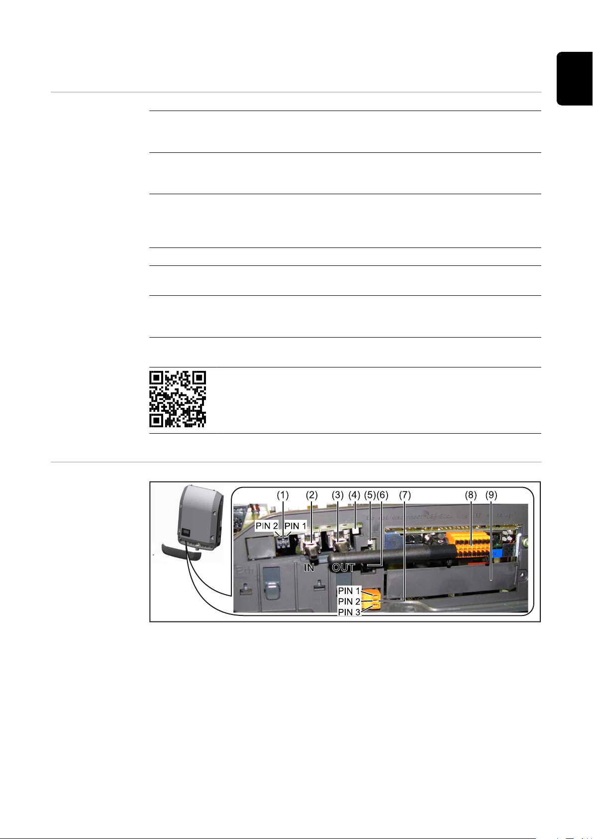
Data communication area
Depending on the model, the inverter may be equipped with the Fronius
Datamanager plug-in card (8).
13
Page 14

Ite
m Description
(1) Switchable multifunction current interface.
For more details, refer to the section below entitled "Explanation of the
multifunction current interface"
Use the 2-pin mating connector supplied with the inverter to connect to
the multifunction current interface.
(2)
(3)
(4) The "Fronius Solar Net" LED
(5) The "Data transfer" LED
(6) USB A socket
(7) Floating switch contact (relay) with mating connector
IN Fronius Solar Net connection / interface protocol IN
OUT Fronius Solar Net connection / interface protocol
"Fronius Solar Net" / interface protocol input and output for connecting
to other DATCOM components (e.g. inverter, Fronius sensor box, etc.)
If several DATCOM components are linked together, a terminating plug
must be connected to every free IN or OUT connection on a DATCOM
component.
For inverters with a Fronius Datamanager plug-in card, two terminating
plugs are supplied with the inverter.
indicates whether the Fronius Solar Net power supply is available
flashes while the USB flash drive is being accessed. The USB flash drive
must not be removed while recording is in progress.
for connecting a USB flash drive with maximum dimensions of
65 x 30 mm (2.6 x 2.1 in.)
The USB flash drive can function as a datalogger for any inverter that it
is connected to. The USB flash drive is not included in the scope of supply of the inverter.
Description of
the "Fronius Solar Net" LED
Max. 250 V AC / 4 A AC
Max. 30 V DC / 1 A DC
Max. 1.5 mm² (AWG 16) cable cross-section
Pin 1 = NO contact (normally open)
Pin 2 = C (common)
Pin 3 = NC contact (normally closed)
For a more detailed explanation, please see the "Menu items in the
Setup menu / Relay" section.
Use the mating connector supplied with the inverter to connect to the
floating switch contact.
(8) Fronius Datamanager with WLAN antenna
or
cover for option card compartment
(9) Cover for option card compartment
The "Fronius Solar Net" LED is on:
the power supply for data communication within the Fronius Solar Net / interface protocol is OK
14
Page 15

The "Fronius Solar Net" LED flashes briefly every 5 seconds:
1 2
3
IN
OUT
°C
W/m²
m/s
IN
OUT
IN
OUT
Sensor Box
WLAN
* Fronius Datamanager
*
IN
OUT
data communication error in the Fronius Solar Net
Overcurrent (current flow > 3 A, e.g. resulting from a short circuit in the
-
Fronius Solar Net ring)
Undervoltage (not a short circuit, voltage in Fronius Solar Net < 6.5 V, e.g. if
-
there are too many DATCOM components on the Fronius Solar Net and not
enough electrical power is available)
In this case, power for the Fronius DATCOM components must be supplied
by connecting an additional power supply (43,0001,1194) to one of the
Fronius DATCOM components.
To detect the presence of an undervoltage, check some of the other Fronius
DATCOM components for faults as required.
After cutting out because of overcurrent or undervoltage, the inverter attempts
to restore the power supply in the Fronius Solar Net every 5 seconds while the
fault is still present.
Once the fault is rectified, power to the Fronius Solar Net will be restored within
5 seconds.
Example Recording and archiving data from the inverter and sensor using a Fronius
Datamanager and a Fronius Sensor Box:
EN
Data network with 3 inverters and a Fronius Sensor Box:
- Inverter 1 with Fronius Datamanager
- Inverters 2 and 3 without Fronius Datamanager!
The external communication (Fronius Solar Net) takes place on the inverter via
the data communication area. The data communication area contains two RS 422
interfaces as inputs and outputs. RJ45 plug connectors are used to make the
connection.
IMPORTANT! Since the Fronius Datamanager functions as a datalogger, the
Fronius Solar Net ring must not include any other datalogger.
There must only be one Fronius Datamanager in each Fronius Solar Net ring.
Fronius Symo 3 - 10 kW: Any other Fronius Datamanagers must be removed and
the unoccupied option card slot sealed off using the blanking cover
(42,0405,2020 - available from Fronius as an optional extra); alternatively, use an
inverter without Fronius Datamanager (light version).
Fronius Symo 10 - 20 kW, Fronius Eco: Any other Fronius Datamanagers must be
removed and the unoccupied option card slot sealed off by replacing the cover
(item number 42,0405,2094); alternatively, use an inverter without Fronius
Datamanager (light version).
= Terminating plug
15
Page 16

Explanation of
the multifunction current interface
Various wiring variants can be connected to the multifunction current interface.
However, these cannot be operated simultaneously. For example, if an S0 meter
is connected to the multifunction current interface, it is not possible to connect
a signal contact for the surge protection device (or vice versa).
Pin 1 = measurement input: max. 20 mA, 100 Ohm measurement resistor (load
impedance)
Pin 2 = max. short circuit current 15 mA, max. open-circuit voltage 16 V DC or
GND
Wiring diagram variant 1: Signal contact for surge protective device
Depending on the setting in the Basic menu (Signal Input submenu), the DC SPD
option (surge protective device) either outputs a warning or an error on the display. Further information on the DC SPD option can be found in the Installation
Instructions.
Wiring diagram variant 2: S0 meter
A meter for recording the self-consumption of each S0 can be connected directly to the inverter. This S0 meter can be positioned directly at the feed-in point
or in the consumption branch.
IMPORTANT! In order to connect an S0 meter to the inverter, it may be necessary to update the inverter firmware.
The S0 meter must comply with the IEC62053-31 Class B standard
Recommended max. pulse rate of the S0 meter:
PV output kWp [kW] Max. pulse rate per kWp
30 1000
20 2000
10 5000
≤ 5.5 10000
With this meter, dynamic power reduction can be performed in two ways:
Dynamic power reduction by means of inverter
-
For more information see chapter Dynamic power reduction by means of in-
verter on page 17
Dynamic power reduction by means of the Fronius Datamanager 2.0
-
for more info see: manuals.fronius.com/html/4204260191/
#0_m_0000017472
16
Page 17

Dynamic power
reduction by
means of inverter
Energy companies or grid operators may impose feed-in limits on an inverter. Dynamic power reduction takes account of self-consumption by the household before the power of an inverter is reduced:
A counter for determining self-consumption of the S0 can be connected directly
to the inverter – see chapter Explanation of the multifunction current interface
on page 16
A feed-in limit can be set in the Basic menu under Signal input – S0 meter – see
chapter Menu items in the Basic menu on page 45.
Setting options for S0 meter:
Grid feed-in limit
-
Field for entering the maximum grid feed-in power in W. If this value is exceeded, the inverter regulates down to the set value within the time required
by national standards and regulations.
Pulses per kWh
-
Field for entering the pulses per kWh of the S0 meter.
Zero feed-in is possible with this configuration.
When using the S0 meter and power reduction by means of an inverter, the S0
meter must be installed in the consumption branch.
EN
S0 meter in the consumption branch
If dynamic power reduction is subsequently configured using the Fronius
Datamanager 2.0 (Inverter user interface - UC Editor menu - Dynamic power reduction), dynamic power reduction must be deactivated using the inverter (Inverter display - Basic menu - Signal input - S0 meter).
17
Page 18

Fronius Datamanager 2.0
(5)
(1)
(6)(7)
(10) (8)(9)
(4)
(2)
(3)
Controls, connections and displays on the
Fronius
Datamanager 2.0
No. Function
(1) IP switch
For switching the IP address:
Switch position A
Default IP address with opening of the WLAN access point
Fronius Datamanager 2.0 uses the set IP address 169.254.0.180 to
establish a direct connection to a PC via LAN.
Setting the IP switch to position A also opens an access point to enable a direct WLAN connection to the Fronius Datamanager 2.0.
Access data for this access point:
Network name: FRONIUS_240.XXXXXX
Code: 12345678
Access to the Fronius Datamanager 2.0 is possible:
Using the DNS name "http://datamanager"
-
Using the IP address 169.254.0.180 for the LAN interface
-
Using the IP address 192.168.250.181 for the WLAN access
-
point
Switch position B
Assigned IP address
The Fronius Datamanager 2.0 uses an assigned IP address (factory
setting dynamic (DHCP))
The IP address can be set on the Fronius Datamanager 2.0 website.
18
Page 19

No. Function
D-
-
-
1
3
5
7
9
D+
+
+
0
2
4
6
8
I IO RS485
(2) WLAN LED
Flashing green: Fronius Datamanager 2.0 is in Service mode
-
(IP switch on the Fronius Datamanager 2.0 plug-in card is in position A or Service mode has been activated via the inverter display,
the WLAN access point is open)
Lights up green: WLAN connection established
-
Flashing green/red (alternately): WLAN access point has timed out
-
following activation (1 hour)
Lights up red: no WLAN connection
-
Flashing red: faulty WLAN connection
-
Does not light up: Fronius Datamanager 2.0 is in Slave mode
-
(3) Solar.web connection LED
Lights up green: Fronius Solar.web connection established
-
Lights up red: Fronius Solar.web connection is required but has not
-
been established
Does not light up: no connection to Fronius Solar.web is required
-
(4) Supply LED
Lights up green: Fronius Solar Net is providing an adequate power
-
supply; Fronius Datamanager 2.0 is ready for use.
Does not light up: insufficient or no power supply from Fronius Sol-
-
ar Net - an external power supply is required
or
the Fronius Datamanager 2.0 is in Slave mode
Flashing red: update in progress
-
EN
IMPORTANT! Never interrupt the power supply while an update is
in progress.
Lights up red: update failed
-
(5) Connection LED
Lights up green: connection established within Fronius Solar Net
-
Lights up red: connection within Fronius Solar Net interrupted
-
Does not light up: Fronius Datamanager 2.0 is in Slave mode
-
(6) LAN connection
Ethernet interface, colour-coded blue, for connecting the Ethernet
cable
(7) I/Os
Digital inputs and outputs
19
Page 20

No. Function
Modbus RTU 2-wire (RS485):
D- Modbus data D+ Modbus data +
Int./ext. power supply
- GND
+ U
int
/ U
ext
Internal voltage output 12.8 V
or
input for an external supply voltage
>12.8 - 24 V DC (+ 20%)
Digital inputs: 0 - 3, 4 - 9
Voltage level: low = min. 0V - max. 1.8V; high = min. 3V - max. 24V DC (+
20%)
Input currents: dependent on input voltage; input resistance = 46 kOhm
Digital outputs: 0 - 3
Switching capacity when power is supplied by the Fronius Datamanager
2.0 plug-in card: 3.2 W in total for all 4 digital outputs
Switching capacity when power is supplied by an external power supply
delivering min. 12.8 - max. 24 V DC (+ 20%), connected to Uint / Uext
and GND: 1 A, 12.8 - 24 V DC (depending on external power supply) for
each digital output
The connection to the I/Os is established via the mating connector supplied.
(8) Antenna socket
This is where the WLAN antenna is connected
(9) Modbus termination switch (for Modbus RTU)
Internal bus terminator with 120 ohm resistor (yes/no)
Switch in "on" position: 120 ohm terminating resistor active
Switch in "off" position: no terminating resistor active
IMPORTANT! On an RS485 bus, the terminating resistor on the first
and last device must be active.
20
(10) Fronius Solar Net Master / Slave switch
To switch from master to slave mode within a Fronius Solar Net ring
IMPORTANT! In slave mode, all the LEDs on the Fronius Datamanager
2.0 plug-in card are off.
Page 21

Fronius
Datamanager
during the night
or when the
available DC
voltage is insufficient
The Night Mode parameter under "Display Settings" in the Setup menu is preset
to OFF in the factory.
For this reason the Fronius Datamanager cannot be accessed during the night or
when the available DC voltage is insufficient.
To nevertheless activate the Fronius Datamanager, switch the inverter off and on
again at the mains and press any function button on the inverter display within
90 seconds.
See also the chapters on "Menu items in the Setup menu", "Display settings"
(Night Mode).
EN
Starting for the
first time
Starting the Fronius Datamanager 2.0 for the first time is made considerably
easier with the Fronius Solar.start app. The Fronius Solar.start app is available in
the respective app stores.
When starting the Fronius Datamanager 2.0 for the first time,
the Fronius Datamanager 2.0 plug-in card must be installed in the inverter,
-
or
there must be a Fronius Datamanager Box 2.0 in the Fronius Solar Net ring.
-
IMPORTANT! In order to establish a connection to Fronius Datamanager 2.0,
"Obtain IP address automatically (DCHP)" must be activated on the end device in
question (e.g. laptop, tablet, etc.).
NOTE!
If the photovoltaic system has only one inverter, steps 1 and 2 below can be
skipped.
In this case, starting for the first time will commence with step 3.
Connect inverter with Fronius Datamanager 2.0 or Fronius Datamanager Box
1
2.0 to the Fronius Solar Net
When networking several inverters in Fronius SolarNet:
2
Set the Fronius Solar Net client/server switch on the Fronius Datamanager
2.0 plug-in card correctly
One inverter with Fronius Datamanager 2.0 = master
-
All other inverters with Fronius Datamanager 2.0 = slave (the LEDs on
-
the Fronius Datamanager 2.0 plug-in cards are not illuminated)
Switch the device to Service mode
3
Activate the WiFi Access Point via the Setup menu on the inverter
-
21
Page 22

Stand by
WiFi Access Point
DATCOM
USB
Clock
The inverter establishes the WLAN access point. The WLAN access point remains open for 1 hour. The IP switch on the Fronius Datamanager 2.0 can remain
in switch position A due to the activation of the WiFi Access Point.
Installation using the Solar.start
app
Download Fronius Solar.start
4
Run the Fronius Solar.start app
5
Installation using a web browser
Connect the end device to the
4
WLAN access point
SSID = FRONIUS_240.xxxxx (5-8
digits)
Search for a network with the
-
name "FRONIUS_240.xxxxx"
Establish a connection to this
-
network
Enter the password 12345678
-
(Alternatively, connect the end
device and inverter using an Ethernet cable.)
Enter the following in the
5
browser:
http://datamanager
or
192.168.250.181 (IP address for
WLAN connection)
or
169.254.0.180 (IP address for
LAN connection)
22
The Setup wizard start page is displayed.
The technician wizard is intended for the installer and contains standard-specific
settings. Running the technician wizard is optional.
If the technician wizard is run, it is vital to note the service password that is is-
Page 23

sued. This service password is necessary for setting the "DNO Editor" menu item.
If the technician wizard is not run, no specifications regarding power reduction
are set.
Running the Fronius Solar.web wizards is mandatory.
Run the Fronius Solar.web wizards and follow the instructions
6
The Fronius Solar.web homepage is displayed,
or
the Fronius Datamanager 2.0 web page is displayed.
Where necessary, run the technician wizard and follow the instructions
7
EN
Further information on Fronius
Datamanager 2.0
Further information on the Fronius Datamanager 2.0 and other start-up options can be found at:
→ http://www.fronius.com/QR-link/4204260191DE
23
Page 24

Controls and indicators
(1)
(2)
(3)
(4)
(5) (6) (7) (8)
Controls and displays
Item Description
(1) Display
For displaying values, settings and menus
Monitoring and status LEDs
(2) Initialisation LED (red) lights up
During the initialisation phase when starting up the inverter
-
If, when starting up the inverter in the initialisation phase, there is
-
a continuous hardware fault
(3) Status LED (orange) lights up
If, after the initialisation phase, the inverter is in its automatic
-
startup or self-test phase (as soon as the solar modules are delivering sufficient power after sunrise)
If status codes (STATE Codes) are shown on the inverter display
-
If the inverter has been switched to Standby mode in the Setup
-
menu (= feeding energy into the grid switched off manually)
If the inverter software is being updated
-
(4) Operating status LED (green) lights up
If the PV system is working correctly after the inverter's automat-
-
ic startup phase
all the time while energy is being fed into the grid
-
Function keys - allocated different functions depending on the selection:
(5) "Left/up" key
For navigating to the left and up
(6) "Down/right" key
For navigating down and to the right
24
(7) "Menu/Esc" key
For switching to the menu level
For quitting the Setup menu
(8) "Enter" key
For confirming a selection
The keys operate capacitively. Exposure to water may impair their function. If necessary, wipe the keys dry with a cloth to ensure optimum functionality.
Page 25

Display Power for the display comes from the mains voltage. Depending on the setting
selected in the Setup menu, the display can be kept on all day.
IMPORTANT! The display on the inverter is not a calibrated measuring device.
A slight inaccuracy in comparison with the energy meter used by the energy
company is intrinsic to the system. A calibrated meter will be needed to calculate
the bills for the power supply company.
Display areas in Display mode
EN
Display areas in Setup mode
(*) Scroll bar
(**) The Energy Manager symbol
is displayed when the Energy Manager function is activated
(***) Inv. no. = Inverter DATCOM number,
Save symbol - appears briefly while set values are being saved,
USB connection - appears if a USB stick has been connected
25
Page 26

Navigation at the menu level
Activating display backlighting
Automatic deactivation of display backlighting / changing to
the "NOW" menu
item
Opening the
menu level
Press any key
1
The display backlighting is activated.
There is an option under "Display Settings - Backlighting" in the SETUP menu
to set the display backlighting so that it is on all the time or off all the time.
If two minutes pass without any button being pressed, the display backlighting
switches off automatically and the inverter goes to the "NOW" menu item (assuming the display backlighting is set to AUTO).
The automatic selection of the "NOW" menu item can happen from any position
on the menu level, unless the inverter was manually switched into the "Standby"
operating mode.
After automatically selecting the "NOW" menu item, the current power of feeding in is displayed.
1
Press "ESC"
The display switches to the menu level.
2
Using the "Left" or "Right" keys select the desired menu item
3
Press the "Enter" key to select the
desired menu item
The menu items
NOW
-
Displays real-time values
LOG
-
Data recorded today, during the current calendar year and since the inverter
was started for the first time
GRAPH
-
Day characteristic displays a plot showing the output power during the day.
The time axis is scaled automatically. Press the "Back" key to close the display
SETUP
-
Setup menu
INFO
-
Information about the device and the software
26
Page 27

Values displayed
under the NOW
menu item
Output power (W) - depending on the device type (MultiString), when the
Enter key is pressed, the individual output powers for MPP Tracker 1 and
MPP Tracker 2 (MPPT1 / MPPT2) are displayed
AC reactive power (VAr)
Grid voltage (V)
Output current (A)
Grid frequency (Hz)
Solar voltage (V) - U PV1 from MPP Tracker 1 and U PV2 from MPP Tracker 2
(MPPT1 / MPPT2), if MPP Tracker 2 is activated (see "The Basic menu" - "Menu
items in the Basic menu")
Solar power (A) - I PV1 from MPP Tracker 1 and I PV2 from MPP Tracker 2
(MPPT1 / MPPT2), if MPP Tracker 2 is activated (see "The Basic menu" - "Menu
items in the Basic menu")
Fronius Eco: The total current from both measuring channels is displayed. Both
channels are shown separately in SolarWeb.
Time date - Time and date on the inverter or in the Fronius Solar Net ring
EN
Values displayed
under the LOG
menu item
Energy fed in (kWh / MWh)
Energy fed into the grid during the period in question.
When the Enter key is pressed, the individual output powers for MPP
Tracker 1 and MPP Tracker 2 (MPPT1 / MPPT2) are displayed, if MPP Tracker 2
is activated (see "The Basic menu" - "Menu items in the Basic menu")
There may be discrepancies compared with values displayed on other measuring instruments because of differences in measuring methods. As far as the
billing of the energy fed in is concerned, the only binding display values are
those produced by the calibrated measuring instrument provided by the utility
company.
Max. output power (W)
Largest amount of energy fed into the grid during the period in question.
When the Enter key is pressed, the individual output powers for MPP
Tracker 1 and MPP Tracker 2 (MPPT1 / MPPT2) are displayed, if MPP Tracker 2
is activated (see "The Basic menu" - "Menu items in the Basic menu")
Yield
Amount of money earned during the period in question
Like the "Energy fed in" figure, the yield figure may also exhibit discrepancies
compared with other measured values.
The subitem "Energy yield" in the "Menu items in the Set-up menu" section explains how to select a currency and charge rate.
The factory setting depends on the respective country setup.
CO2 savings
CO2 emissions saved during the period in question
The subitem "CO2 factor" in the "Menu items in the Set-up menu" section explains how to set the CO2 factor.
27
Page 28

Maximum grid voltage (V) [phase indicator - neutral or phase - phase]
Highest grid voltage measured during the period in question
When the Enter key is pressed, the individual grid voltages are listed
Maximum solar voltage (V)
Highest solar module voltage measured during the period in question
When the Enter key is pressed, the voltage values for MPP Tracker 1 and
MPP Tracker 2 (MPPT1 / MPPT2) are displayed, if MPP Tracker 2 is activated
(see "The Basic menu" - "Menu items in the Basic menu")
Operating hours
Length of time the inverter has been working (HH:MM).
IMPORTANT! In order for the day and year values to be displayed correctly,
the time must be set accurately.
28
Page 29

SETUP menu item
GRAPH
Relay
Relay
GRAPH
Initial setting The inverter is pre-configured after commissioning has been completely carried
out (e.g. using the Installation Wizard) according to the country setup.
The SETUP menu item allows the initial settings of the inverter to be changed
easily to bring it in line, as closely as possible, with the preferences and requirements of the user.
EN
Software updates
Navigating the
SETUP menu
item
IMPORTANT! As a result of software updates, you may find that your device has
certain functions that are not described in these Operating Instructions, or vice
versa. Certain illustrations may also differ slightly from the actual controls on
your device, but these controls function in exactly the same way.
Entering the SETUP menu item
At the menu level, use the "Left" or
1
"Right" keys to select the "SETUP"
menu item
2
Press the "Enter" key
The first entry under the SETUP menu item
is displayed:
"Standby"
Scrolling between the entries
Exiting an entry
If no key is pressed for 2 minutes:
3
Use the "Up" and "Down" keys to
scroll between the available entries
To exit a menu entry, press the "Back"
4
key
The menu level appears
29
Page 30

The inverter switches from wherever it is on the menu level back to the
-
"NOW" display mode (exception: "Standby" Setup menu item).
The display backlighting goes out unless it has been set to ON in Display Set-
-
ting - Backlighting (see Display Setting - Backlighting).
The power currently being fed in is displayed or the currently active state
-
code is displayed.
Setting menu
entries, general
Open the desired menu
1
2
Use the 'Up' or 'Down' keys to select the desired menu item
3
Press "Enter"
The available settings are displayed: The first digit of a value to be set
flashes:
Use the 'Up' or 'Down' buttons to
4
select the desired setting
Press the 'Enter' key to save and
5
Use the 'Up' or 'Down' keys to se-
4
lect a value for the first digit
5
Press "Enter"
apply the setting.
The second digit of the value flashes.
To discard the setting, press the
Repeat steps 4 and 5 until ...
'Esc' key.
6
the whole value to be set flashes.
7
Press "Enter"
Repeat steps 4 - 6 as required for
8
units or other values that are to
be set until the appropriate unit
or the value flashes.
Press the 'Enter' key to save and
9
apply the changes.
Application example: Setting
the time
The currently selected menu item is
displayed.
To discard the changes, press the
'Esc' key.
The currently selected menu item is
displayed.
Select "Clock" from the Setup menu
1
.
2
Press the "Enter" key
30
Page 31

An overview of the values that can be
changed is displayed.
3
Use the "Up" and "Down" keys Select
"Set time"
4
Press the "Enter" key
The current time appears. (HH:MM:SS, 24hour clock), the "tens" digit for the hour will
flash.
5
Use the "Up" and "Down" keys to select a value for the first digit of the code
6
Press the "Enter" key
The "units" digit for the hour will flash.
Repeat steps 5 and 6 to set the "units"
7
digit for the hour, for the minutes and for
the seconds until...
EN
the set time starts flashing.
8
Press the "Enter" key
The time is applied and the overview of values that can be changed is displayed.
4
Press the "Esc" key
The "Clock" item on the Setup menu appears.
31
Page 32
Menu items in the Set-up menu
Standby Manual activation / deactivation of Standby mode
No energy is fed into the grid.
-
The Startup LED will show steady orange.
-
In the display, STANDBY / ENTER are alternately displayed
-
In Standby mode, no other menu item at menu level can be accessed or ad-
-
justed.
The automatic switchover into the "NOW" display mode after 2 minutes of
-
keyboard inactivity does not occur.
Standby mode can only be terminated manually by pressing the "Enter" key.
-
Pressing "Enter" at any time will cause energy to resume feeding into the
-
grid, as long as there is no error (state code)
Switching off Standby mode (manually switching off feeding energy into the
grid):
Select the "Standby" item
1
2
Press "Enter" function key
"STANDBY" and "ENTER" appear alternately on the display.
Standby mode is now active.
The Startup LED shows steady orange.
Resuming feeding energy into the grid:
In standby mode, the display alternates between 'STANDBY' and 'ENTER'.
1
Press the "Enter" function key to resume feeding energy into the grid
The "Standby" menu item is displayed.
At the same time, the inverter enters the startup phase.
The operating state LED shows steady green when feeding energy into the grid
has been resumed.
DATCOM Checking data communications, entering the inverter number, protocol settings
Setting range Status / inverter number / protocol type
Status
Indicates data communication is taking place via Fronius Solar Net or that a
data communications error has occurred
Inverter number
Sets the number (= address) of the inverter in a system with several inverters
Setting range 00 - 99 (00 = inverter address 100)
32
Factory setting 01
IMPORTANT! If a number of inverters are linked together in a data communications system, assign a unique address to each one.
Protocol type
Specifies the communications protocol to be used to transfer the data:
Page 33
Setting range Solar Net / Interface *
Factory setting Fronius Solar Net
* The protocol type "Interface" only functions when there is no Datamanager
card in the inverter. All Fronius Datamanager cards should be removed from
the inverter.
USB Running firmware updates or saving detailed information from the inverter to the
USB flash drive
Setting range Safely remove hardware / Software update / Logging in-
terval
Safely remove hardware
To remove a USB flash drive from the USB A socket on the plug-in data communications card without losing any data.
The USB flash drive can be removed:
If the OK message appears
-
when the "Data transfer" LED stops flashing or comes on steady
-
Software update
To update the inverter firmware using a USB flash drive.
EN
Procedure:
Download the relevant firmware update file "froxxxxx.upd"
1
(e.g. from http://www.fronius.com; xxxxx stands for the version number)
NOTE!
To successfully update the inverter software, the USB flash drive provided for
the purpose must not have a hidden partition or any encryption (see chapter
"Suitable USB flash drives").
Save the firmware update file to the highest data level of the USB flash drive
2
Open the lid of the data communication area on the inverter
3
Plug the USB flash drive containing the firmware update file into the USB
4
socket in the inverter's data communication area
Select "USB" from the Setup menu, followed by "Software update"
5
Press the "Enter" key
6
Wait until the version currently installed on the inverter and the new firm-
7
ware version are displayed for comparison:
First Page: Recerbo software (LCD), key controller software (KEY), coun-
-
try setup version (Set)
Second Page: Power stage set software (PS1/PS2)
-
Press the "Enter" function button after each page
8
The inverter starts copying the data.
"BOOT" and the progress of storing the individual tests expressed in % are displayed until all the data for all the electronic modules has been copied.
Once copying is complete, the inverter updates the electronic modules as required in sequence.
"BOOT", the affected modules and the update progress in % are displayed.
33
Page 34
The final step is for the inverter to update the display.
The display remains dark for approx. 1 minute while the monitoring and status
LEDs flash.
Once the firmware update is complete, the inverter enters its start-up phase before going on to start feeding energy into the grid. Unplug the USB flash drive using the "Safely remove hardware" function.
When the inverter firmware is updated, any custom settings that were configured
in the Setup menu are retained.
Logging interval
Activate / deactivate the USB logging function and specify a logging interval
Unit Minutes
Setting range 30 min. / 20 min./ 15 min./ 10 min./ 5 min./ No log
Factory setting 30 min.
30 min. The logging interval is 30 minutes; every 30 minutes new
logging data will be saved to the USB flash drive.
20 min.
Relay (floating
contact switch)
15 min.
10 min.
5 min. The logging interval is 5 minutes; every 5 minutes new
logging data will be saved to the USB flash drive.
No log No data is saved
IMPORTANT! In order for the USB logging function to work correctly the time
must be set correctly. Setting the time is discussed in the section "Menu items in
the Setup menu" - "Clock".
Status codes (state codes), the status of the inverter (e.g. feeding energy into the
grid) or Energy Manager functions can be displayed using the floating switch contact (relay).
Setting range Relay mode / Relay test / Switch-on point* / Switch-off
point*
* these are only shown if the "E-Manager" function has been activated under "Relay mode".
34
Relay mode
The following functions can be shown using relay mode:
Alarm function (Permanent / ALL / GAF)
-
Active output (ON / OFF)
-
Energy Manager (E-Manager)
-
Setting range ALL / Permanent / GAF / OFF / ON / E-Manager
Factory setting ALL
Page 35

Alarm function:
ALL / Permanent:
GAF As soon as GAF mode is selected, the relay is switched on.
Active output:
ON: The floating NO contact is on all the time the inverter is in op-
Switching the floating switch contact for permanent and temporary service codes (e.g. brief interruption to energy being
fed into the grid, a service code occurs a certain number of
times a day - can be adjusted in the "BASIC" menu)
The relay opens as soon as the power stage set registers an
error and goes from normally feeding energy into the grid to
being in an error state. This means that the relay can be used
for fail-safe functions.
Application example
It may be necessary to perform phase compensation when using a single-phase inverter at a multiphase site. If an error occurs on one or several inverters and the connection to the grid
is broken, the other inverters must also be disconnected to
maintain the phase balance. The "GAF" relay function can be
used in conjunction with the Datamanager or an external protection device to recognise or signal that an inverter is not
feeding in or is disconnected from the grid and to then disconnect the remaining inverters from the grid using a telecontrol command.
eration (as long as the display is not dark or is displaying
something).
EN
OFF: The floating NO contact is off.
Energy Manager:
E-Manager: Further details on the "Energy Manager" function may be
found in the "Energy Manager" section.
Relay test
Function test to determine whether the floating switch contact switches
Switch-on point (only if "Energy Manager" function is activated)
for setting the effective power limit beyond which the floating switch contact is
switched on
Factory setting 1000 W
Setting range Set switch-off point up to the maximum nominal output
of the inverter (W or kW)
Switch-off point (only if "Energy Manager" function is activated)
for setting the effective power limit beyond which the floating switch contact is
switched off
Factory setting 500
Setting range 0 to the set switch-on point of the inverter (W or kW)
Energy Manager
(under Relay
menu item)
The "Energy Manager" (E-Manager) function can be used to activate the floating
switch contact in such a way that it functions as an actuator.
Thus, a consumer that is connected to the floating switch contact can be controlled by specifying a switch-on or switch-off point that depends on the feed-in
power (effective power).
35
Page 36
The floating switch contact is automatically switched off:
If the inverter is not feeding any power into the grid
-
If the inverter is manually switched to Standby mode
-
If the effective power is set to < 10% of the nominal output of the inverter.
-
To activate the Energy Manager function, select the "E-Manager" item and press
the "Enter" key.
When the "Energy Manager" function is running, the "Energy Manager" symbol
will appear in the top left corner of the display:
When the floating NO contact is off (open contact)
When the floating NC contact is on (closed contact)
To deactivate the Energy Manager function, select a different function (ALL /
Permanent / OFF / ON) and press the "Enter" key.
NOTE!
Notes on setting up the switch-on and switch-off points
If the difference between the switch-on and switch-off points is too small, or if
there are fluctuations in effective power, the result may be multiple switching
cycles.
To avoid switching on and off frequently, the difference between the switch-on
and switch-off points should be at least 100 - 200 W.
When choosing the switch-off point, the power consumption of the connected
consumer should be taken into account.
When choosing the switch-on point, the weather conditions and anticipated insolation should be taken into account.
Application example
Switch-on point = 2000 W, switch-off point = 1800 W
If the inverter is outputting 2000 W or above, then the floating switch contact on
the inverter is switched on.
If the inverter output falls to below 1800 W, the floating switch contact is
switched off.
This allows useful applications, such as operating a heat pump or an air-conditioning system using as much self-generated power as possible, to be implemented quickly
Time / Date Set the time, date, the display format and automatic changeover between sum-
mer and winter time
36
Setting range Set time / Set date / Time display format / Date display
format / Summer/winter time
Set time
Set the time (hh:mm:ss or hh:mm am/pm – depending on the setting for the
time display format)
Page 37

Set date
Set the date (dd.mm.yyyy or mm/dd/yyyy - depending on the setting for the
date display format)
Time display format
For specifying the time display format
Setting range 12hrs / 24hrs
Factory setting Depends on country setup
Date display format
for specifying the date display format
Setting range mm/dd/yyyy or dd.mm.yy
Factory setting Depends on country setup
Summer/winter time
Activate/deactivate automatic changeover between summer and winter time
IMPORTANT! Only use the automatic summer/winter time changeover function if the Fronius Solar Net ring does not include any LAN- or WLAN-compatible system components (e.g. Fronius Datalogger Web, Fronius Datamanager or
Fronius Hybridmanager).
EN
Display settings
Setting range on / off
Factory setting on
IMPORTANT! The time and date must be set accurately in order for the day
and year values and for the day characteristic to be displayed correctly.
Setting range Language / Night mode / Contrast / Illumination
Language
Set language for display
Setting range English, German, French, Spanish, Italian, Dutch,
Czech, Slovakian, Hungarian, Polish, Turkish, Portuguese, Romanian
Night mode
Night mode controls Fronius DATCOM and inverter display operation during
the night or when the DC voltage is insufficient
Setting range AUTO / ON / OFF
Factory setting OFF
AUTO: Fronius DATCOM mode is always in effect as long as there is a
Fronius Datamanager connected in an active and uninterrupted
Fronius Solar Net.
The inverter display remains dark during the night, but can be activated by pressing any function button.
37
Page 38

ON: Fronius DATCOM mode is always in effect. The inverter supplies 12
V of DC voltage continuously to power the Fronius Solar Net. The
display is always active.
IMPORTANT! If Fronius DATCOM night mode is set to ON or
AUTO when there are Fronius Solar Net components connected,
the inverter's current consumption during the night will increase to
around 7 W.
OFF: Fronius DATCOM will not run at night, the inverter therefore does
not require any power during the night to supply the Fronius Solar
Net with energy.
The inverter display is switched off during the night and the Fronius
Datamanager is not available. To nevertheless activate the Fronius
Datamanager, switch the inverter off and on again at the mains and
press any function button on the inverter display within 90
seconds.
Contrast
Set the contrast on the inverter display
Setting range 0 - 10
Factory setting 5
Since the contrast is temperature-dependent, it may be necessary to adjust
the setting under the "Contrast" menu item when the environmental conditions
change.
Illumination
Initial setting for inverter display illumination
The "Illumination" menu item only relates to the inverter display backlighting.
Setting range AUTO / ON / OFF
Factory setting AUTO
AUTO: The inverter display backlighting is activated by pressing any key. If
no key is pressed for 2 minutes, the display backlighting will go off
again.
ON: The inverter display backlighting remains permanently on when the
inverter is active.
OFF: The inverter display backlighting is permanently switched off.
ENERGY YIELD The following settings can be changed/set here:
Counter deviation / Calibration
-
Currency
-
Feed-in tariff
-
CO2 factor
-
Setting range Currency / Feed-in tariff
38
Page 39

Counter deviation / calibration
Calibrating the counter
Currency
Set the currency
Setting range 3 characters, A-Z
Feed-in tariff
Set the remuneration rate for energy fed into the grid
Setting range 2 digits, 3 decimal places
Factory setting (depends on country setup)
CO2 factor
Setting the CO2 factor of the energy fed into the grid
Fan To check that the fan is working correctly
Setting range Test fan #1 / Test fan #2 (depending on the device)
EN
Use the "Up" and "Down" keys to select the desired fan
-
Testing of the selected fan is initiated by clicking "Enter".
-
The fan will continue to run until the operator exits the menu by pressing
-
"Esc".
IMPORTANT! Nothing will show on the inverter display if the fan is working. The
only way to check how the fan is working is by listening and feeling.
39
Page 40

The INFO menu item
Measured values PV Ins.- Insulation resistance of the PV system
Ext. Lim. - external Limitation
U PV 1 / U PV 2* (U PV 2 is not available on the Fronius Symo 15.0-3 208)
Current DC voltage at the DC input terminals, even if the inverter is feeding no
power into the grid whatsoever (from the 1st or 2nd MPP Tracker)
* MPP Tracker 2 must be switched to ON via the Basic menu
GVDPR - Grid voltage-dependent power reduction
Fan #1 - Percentage of target output for fan
PSS status IMPORTANT! Due to the low level of insolation early in the morning and in the
evening, the status codes STATE 306 (Power low) and STATE 307 (DC low) are
displayed routinely at these times of day. These status codes do not indicate any
kind of fault at this point in time.
The status of the most recent inverter fault can be displayed.
Press the "Enter" key to see the status of the power stage set and the most
-
recent fault
Use the "Up" and "Down" keys to scroll through the list
-
Press the "Back" key to close the status and fault list
-
Grid status The five most recent grid faults can be displayed:
Press the 'Enter' key to see the five most recent grid faults
-
Use the 'Up' and 'Down' keys to scroll through the list
-
Press the 'Back' key to close the grid fault display
-
Device information
General: Device type - the exact name of the inverter
Country-specific
setting:
MPP Tracker: Tracker 1 - indicates the set tracking behaviour (MPP AUTO / MPP USER /
For displaying the settings that will be of relevance to a power supply company.
The values shown will depend on the country setup or the device-specific settings of the inverter.
fam. - inverter family of the inverter
serial number - serial number of the inverter
Setup - specified country setup
Version - version of country setup
Origin activated - indicates that the normal country-specific setup is activ-
ated.
Group - group for updating the inverter software
FIX)
Tracker 2 (only on Fronius Symo except for Fronius Symo 15.0-3 208) - indicates the set tracking behaviour (MPP AUTO / MPP USER / FIX)
40
Page 41

Grid monitoring: GMTi - Grid Monitoring Time - start-up time of the inverter in sec (seconds)
GMTr - Grid Monitoring Time reconnect - reconnection time in sec (seconds)
after a grid fault
ULL - U (voltage) Longtime Limit - voltage limit value in V (volts) for the 10minute average voltage value
LLTrip - Longtime Limit Trip - trip time for ULL monitoring, how fast the inverter should switch off
EN
Grid voltage limits
inner limit value:
Grid voltage limits
outer limit value
Grid frequency limits:
Q-mode: Indicates which reactive power setting is currently active on the inverter (e.g.
AC power limit including SoftStart indicator and/or AC
grid frequency derating:
UImax - upper inner grid voltage in V (volts)
TTMax - Trip Time Max - trip time for exceeding the upper inner grid voltage
limit value in cyl*
UMin - lower inner grid voltage in V (volts)
TTMin - Trip Time Min - trip time for falling below the lower inner grid
voltage limit value in cyl*
UMax - upper outer grid voltage in V (volts)
TTMax - Trip Time Max - trip time for exceeding the upper outer grid voltage
limit value in cyl*
UMin - lower outer grid voltage in V (volts)
TTMin - Trip Time Min - trip time for falling below the lower outer grid
voltage limit value in cyl*
FILmax - upper inner grid frequency in Hz (Hertz)
FILmin - lower inner grid frequency in Hz (Hertz)
FOLmax - upper outer grid frequency in Hz (Hertz)
FOLmin - lower outer grid frequency in Hz (Hertz)
OFF, Q / P, etc.)
Max P AC - maximum output power, which can be changed using the "Manu-
al Power Reduction" function
GPIS - Gradual Power Incrementation at Startup - indicates (%/sec) whether the SoftStart function is active on the inverter
GFDPRe - Grid Frequency Dependent Power Reduction enable limit - indicates the set grid frequency in Hz (Hertz) from when power derating takes
place
GFDPRv - Grid Frequency Dependent Power Reduction derating gradient indicates the set grid frequency in %/Hz, how strong power derating is
AC voltage derating: GVDPRe - Grid Voltage Depending Power Reduction enable limit - threshold
value in V from which voltage-dependent power derating starts
GVDPRv - Grid Voltage Depending Power Reduction derating gradient - derating gradient %/V with which the power is reduced
Message - indicates whether the dispatch of an info message via Fronius Solar Net is active
*cyl = grid periods (cycles); 1 cyl corresponds to 20 ms at 50 Hz or 16.66 ms at 60 Hz
Version Displays the version and serial numbers of the PC boards in the inverter (e.g. for
service purposes)
Display area Display / Display Software / Integrity Checksum /
Memory Card / Memory Card #1 / Power Stage / Power
Stage Software / EMI Filter / Power Stage #3 / Power
Stage #4
41
Page 42

Switching the key lock on and off
Acess Code
General The inverter has a key lock function.
When the key lock is active, the Setup menu is not accessible, i.e. the setup data
cannot be changed accidentally (or maliciously).
The code 12321 has to be entered in order to activate / deactivate the key lock.
Switching the
key lock on and
off
1
Press the "Menu" key
The menu level appears.
Press the unassigned "Menu / Esc" key
2
5 times
"Access Code" is displayed in the "CODE"
menu; the first digit starts flashing.
Enter the code 12321: Use the "Plus" and
3
"Minus" keys to select a value for the
first digit of the code
4
Press the "Enter" key
The second digit flashes.
Repeat steps 3 and 4 for the second,
5
third, fourth and fifth digits of the access
code until...
the selected code starts flashing.
6
Press the "Enter" key
"Setup Menu Lock" is displayed in the
"LOCK" menu.
7
Use the "Plus" and "Minus" keys to
turn the key lock on or off:
ON = key lock is on (the Setup menu is
not accessible)
OFF = key lock is off (the Setup menu is
accessible)
8
Press the "Enter" key
42
Page 43

USB Stick as a Data Logger and for Updating Inverter Software
USB flash drive
as a datalogger
If a USB flash drive is connected to the USB A socket it can function as a datalogger for an inverter.
At any time, the logging data stored on the USB flash drive can be
imported into the Fronius Solar.access software using the FLD file that was
-
logged at the same time,
viewed directly in third-party programs (e.g. Microsoft® Excel) using the CSV
-
file logged at the same time.
Older versions (before Excel 2007) are limited to a maximum of 65,536 rows.
Further information on "Data on a USB flash drive", "Data volume and storage
capacity" as well as "Buffer memory" can be found at:
Fronius Symo 3 - 10 kW:
EN
® http://www.fronius.com/QR-link/4204260172EN
Suitable USB
flash drives
Fronius Symo 10 - 20 kW, Fronius Eco:
® http://www.fronius.com/QR-link/4204260175EN
Due to the variety of USB flash drives available on the market, it cannot be guaranteed that every USB flash drive will be detected by the inverter.
Fronius recommends that only certified, industry-grade USB flash drives are
used (look out for the USB-IF logo).
The inverter supports USB flash drives with the following file systems:
FAT12
-
FAT16
-
FAT32
-
Fronius recommends that the USB flash drive employed should only be used for
recording logging data or updating the inverter software. The USB flash drives
should not contain any other data.
43
Page 44

USB symbol on the inverter display, e.g. in display mode 'NOW':
AC Output Power
NOW
+
3
5
4
4
1
2
2
Do not disconnect
USB-Stick
while LED is flashing!
X
If the inverter detects a USB flash
drive, the USB symbol will appear in
the top right corner of the display.
When inserting a USB flash drive,
check whether the USB symbol is displayed (it may also flash).
Note! Please note for outdoor applications that conventional USB flash drives
are often only guaranteed to work within a restricted temperature range.
For outdoor applications ensure that the USB flash drive also functions, for example, at low temperatures.
USB flash drive
for updating the
inverter software
Removing the
USB flash drive
With the help of the USB flash drive,
end customers can also update the inverter software via the SETUP menu:
the update file is first saved to the
USB flash drive, from where it is then
transferred to the inverter.
Safety instruction concerning the removal of a USB flash drive:
IMPORTANT! To avoid any loss of
data, a USB flash drive may only be
removed if the following conditions
are met:
Only remove a USB flash drive
-
via the 'Safely remove USB /
HW' item on the SETUP menu
The 'Data transmission' LED has
-
stopped flashing or comes on
steady.
44
Page 45

The Basic menu
Access Code
EN
Access the Basic
menu
1
Press the "Menu” button
The menu level appears.
Press the unassigned "Menu / Esc" key
2
5 times
"Access Code" is displayed in the "CODE"
menu; the first digit starts flashing.
Enter the code 22742: Use the "Plus" and
3
"Minus" keys to select a value for the
first digit of the code
4
Press the "Enter" button
The second digit flashes.
Repeat steps 3 and 4 for the second,
5
third, fourth and fifth digits of the access
code until...
the selected code starts flashing.
Menu items in
the Basic menu
6
Press the "Enter" button
The Basic menu appears.
7
Use the "Plus" and "Minus" keys to select the desired entry
8
Edit the desired menu item by pressing the "Enter" button
9
Press the "Esc" key to exit the Basic menu
The Basic menu is used to set the following parameters, which are important
for installing and operating the inverter:
MPP Tracker 1 / MPP Tracker 2
MPP Tracker 2: ON / OFF (MultiMPP Tracker devices only, excluding
-
Fronius Symo 15.0-3 208)
DC operating mode: MPP AUTO / FIX / MPP USER
-
MPP AUTO: normal operating status; the inverter automatically
-
searches for the ideal operating point
FIX: for entering a fixed DC voltage at which the inverter will operate
-
MPP USER: for entering a lower MP voltage above which the inverter
-
will search for its ideal operating point
Dynamic Peak Manager: ON / OFF
-
Fixed voltage: for entering the fixed voltage
-
MPPT start-up input voltage: for entering the start-up input voltage
-
45
Page 46

USB log book
Activates or deactivates the function for saving all error messages to a USB
flash drive AUTO / OFF / ON
ON: All error messages are automatically saved to a connected USB flash
-
drive.
Input signal
Ext Sig. / S0-Meter / OFF operating mode
-
Ext Sig. operating mode
Triggering method: Warning (warning shown on display) / Ext. Stop
-
(inverter switches off)
Connection type: N/C (normally closed contact) / N/O (normally open
-
contact)
S0 meter operating mode – see chapterDynamic power reduction by
means of inverteron page 17.
Grid feed-in limit
-
Field for entering the maximum grid feed-in power in W. If this value
is exceeded, the inverter regulates down to the set value within the
time required by national standards and regulations.
Pulses per kWh
-
Field for entering the pulses per kWh of the S0 meter.
SMS / relay
Event delay:
-
for entering the time delay after which an SMS is sent or the relay is to
switch
900–86,400 seconds
Event counter:
-
for entering the number of events that lead to signalling:
10–255
Settings if the
"DC SPD" option
is installed
Isolation setting
Isolation warning: ON / OFF
-
Threshold warning: for entering a threshold that leads to a warning
-
Threshold fault: for entering a threshold that leads to a fault (not avail-
-
able in all countries)
TOTAL Reset
Under the LOG menu item, this setting resets the max. and min. voltage values
and the max. power of feeding in to zero.
Once the values have been reset, this action cannot be undone.
To reset the values to zero, press the "Enter" key.
"CONFIRM" is displayed.
Press "Enter" again.
The values are reset and the menu is displayed
If the option: DC SPD (surge protection) has been fitted in the inverter, the following menu items will be set by default:
Signal input: Ext Sig.
Triggering method: Warning
Connection type: N/C
46
Page 47

Autotest
only for Italy
EN
47
Page 48
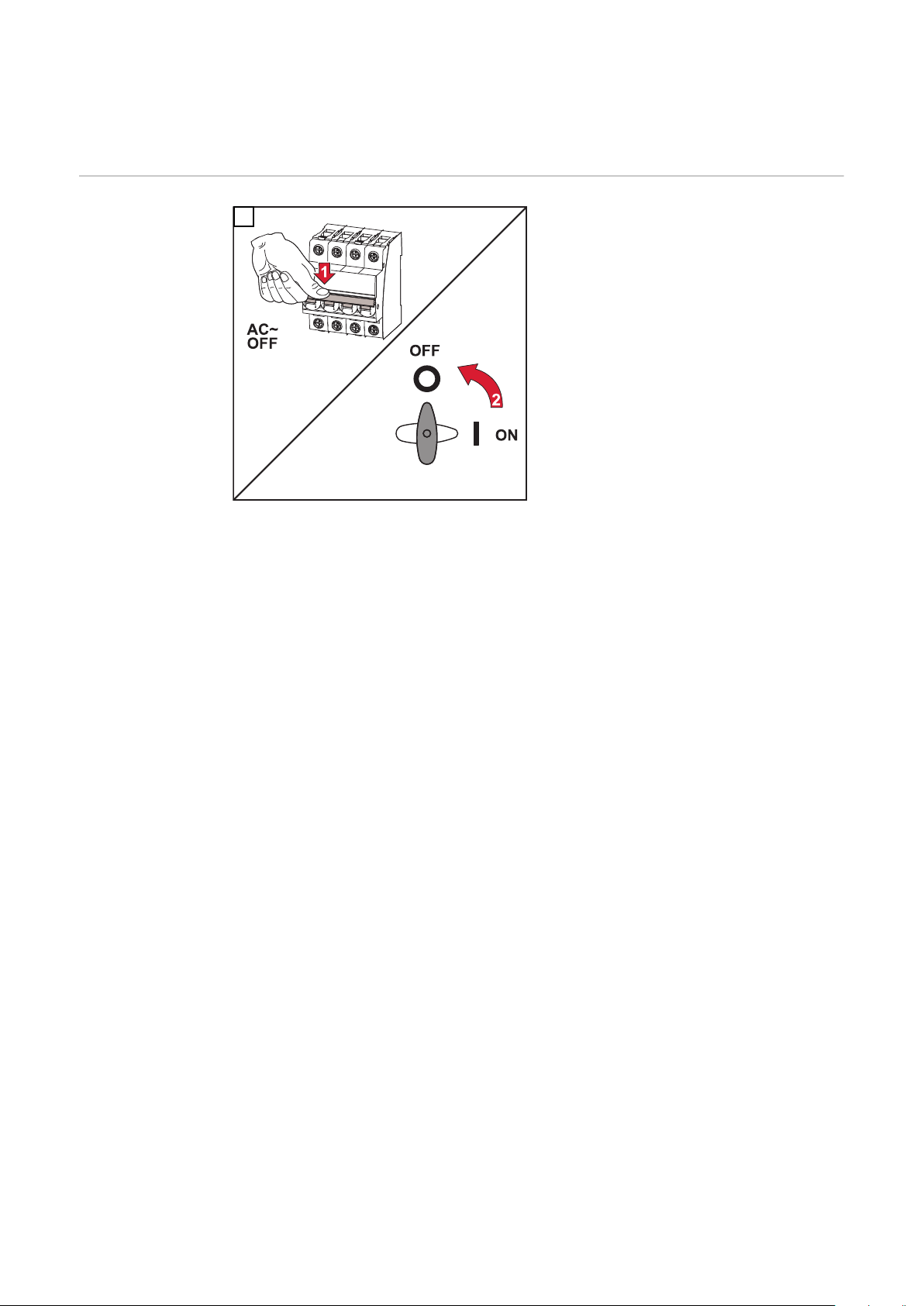
Switching off current supply and restarting the
inverter
Switch off power
to the inverter
Turn off the automatic circuit
1
1.
breaker.
Turn the DC disconnector to the
2.
"Off" switch position.
To start up the inverter again, follow
the steps listed above in reverse order.
48
Page 49
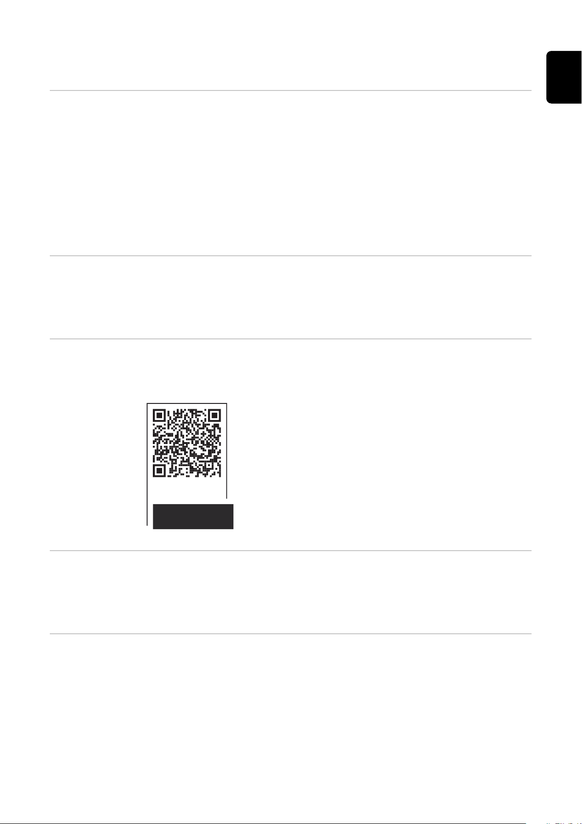
Status diagnostics and troubleshooting
manuals.fronius.com/html/4204101909/#0_t_0000
000061
STATE CODES
Fronius Symo / Eco
EN
Status code display
Total failure of
the display
Status codes in
the e-Manual
The inverter performs a system self-diagnosis that automatically detects many
faults that may occur and shows them on the display. This means you are
promptly made aware of malfunctions in the inverter or the photovoltaic system,
or of any installation or operating faults.
If the system self-diagnosis has detected a specific fault, the associated status
code will be shown on the display.
IMPORTANT! Status codes may sometimes appear briefly as a result of the in-
verter's control response. If the inverter then continues working with no sign of
any problem, this means that there was no fault.
If the display fails to come on some time after sunrise:
Check the AC voltage on the inverter connection sockets:
-
the AC voltage must be 220/230 V (+ 10 % / - 5 %) or 380/400 V (+ 10 % / 5 %).
The latest status codes can be found in the e-Manual version of these Operating
Instructions:https://manuals.fronius.com/html/4204101909/
de.html#0_t_0000000061
Customer service
Operation in
dusty environments
IMPORTANT! Contact your Fronius dealer or a Fronius-trained service techni-
cian if
an error appears frequently or all the time
-
an error appears that is not listed in the tables
-
When operating the inverter in extremely dusty environments:
when necessary, clean the cooling elements and fan on the back of the inverter
as well as the air intakes at the mounting bracket using clean compressed air.
49
Page 50
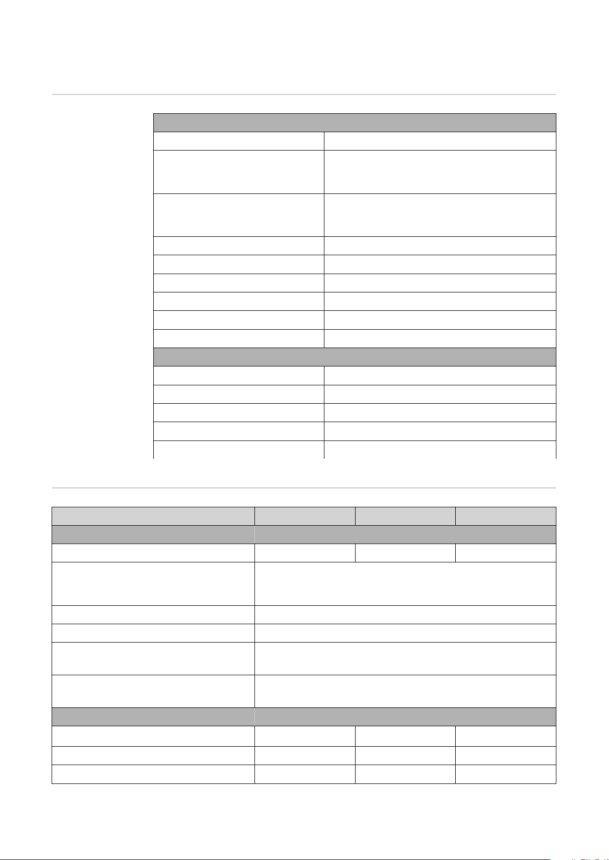
Technical data
General data and
protection
devices Fronius
Symo 3.0-3 -
20.0-3, Fronius
Eco 25.0-3 -
27.0-3
General data
Cooling Controlled forced-air ventilation
Protection class IP 65 (Symo 3.0-3 - 8.2-3)
IP 66 (Symo 10.0-3 - 20.0-3)
IP 66 (Eco 25.0-3 - 27.0-3)
Dimensions h x w x d 645 x 431 x 204 mm (Symo 3.0-3 - 8.2-3)
725 x 510 x 225 mm (Symo 10.0-3 - 20.0-3)
725 x 510 x 225 mm (Eco 25.0-3 - 27.0-3)
Permitted ambient temperature -25 °C - +60 °C
Permissible humidity 0–100%
EMC device class B
DC / AC overvoltage category 2/3
Pollution degree 2
Inverter topology Non-insulated transformerless
Protection devices
DC isolation measurement Integrated
DC overload performance Operating point shift, power limiter
DC disconnector Integrated
RCMU Integrated
Active anti-islanding method Frequency conversion method
Fronius Symo 3.0-3-S 3.7-3-S 4.5-3-S
Input data
MPP voltage range 200–800 V DC 250–800 V DC 300–800 V DC
Max. input voltage
(at 1000 W/m²/ -10 °C in an open circuit)
Min. input voltage 150 V DC
Max. input current 16 A
Max. short-circuit current module ar-
8)
ray
Max. inverter backfeed current to the
3)
array
Output data
1000 V DC
24 A
32 A (RMS)
4)
Nominal output power (P
Max. output power 3000 W 3700 W 4500 W
Rated apparent power 3000 VA 3700 VA 4500 VA
50
) 3000 W 3700 W 4500 W
nom
Page 51
Fronius Symo 3.0-3-S 3.7-3-S 4.5-3-S
Nominal mains voltage 3~ NPE 400 / 230 V or 3~ NPE 380 / 220 V
Min. grid voltage 150 V / 260 V
Max. grid voltage 280 V / 485 V
Nominal output current at 220 / 230 V 4.5 / 4.3 A 5.6 / 5.4 A 6.8 / 6.5 A
Max. output current 9 A
Nominal frequency
Initial short circuit alternating current / phase I
k
50 / 60 Hz
1)
9 A
Total harmonic distortion < 3 %
Power factor (cos phi)
Current (inrush)
5)
Maximum output fault current / dura-
0.7–1 ind./cap.
38 A / 2 ms
21.4 A / 1 ms
2)
tion
General data
Maximum efficiency 98%
European efficiency 96.2% 96.7% 97%
Self-consumption at night < 0.7 W & < 3 VA
EN
Weight 16 kg
Noise emission 58.3 dB(A) ref. 1pW
Fronius Symo 3.0-3-M 3.7-3-M 4.5-3-M
Input data
MPP voltage range 150–800 V DC 150–800 V DC 150–800 V DC
Max. input voltage
1000 V DC
(at 1000 W/m²/ -10 °C in an open circuit)
Min. input voltage 150 V DC
Max. input current 2 x 16.0 A
Max. short-circuit current module array (MPPT1 / MPPT2)
8)
Max. inverter backfeed current to the
3)
array
31 A / 31 A
48 A (RMS)
4)
Output data
Nominal output power (P
) 3000 W 3700 W 4500 W
nom
Max. output power 3000 W 3700 W 4500 W
Rated apparent power 3000 VA 3700 VA 4500 VA
Nominal mains voltage 3~ NPE 400 / 230 V or 3~ NPE 380 / 220
Min. grid voltage 150 V / 260 V
51
Page 52
Fronius Symo 3.0-3-M 3.7-3-M 4.5-3-M
Max. grid voltage 280 V / 485 V
Nominal output current at 220 / 230 V 4.6 / 4.4 A 5.6 / 5.4 A 6.8 / 6.5 A
Max. output current 13.5 A
Nominal frequency
50 / 60 Hz
1)
Initial short circuit alternating current / phase I
K
13.5 A
Total harmonic distortion < 3 %
Power factor (cos phi)
Current (inrush)
5)
Maximum output fault current / dura-
0.85–1 ind./cap.
38 A / 2 ms
24 A / 6.6 ms
2)
tion
General data
Maximum efficiency 98%
European efficiency 96.5% 96.9% 97.2%
Self-consumption at night < 0.7 W & < 3 VA
Weight 19.9 kg
Noise emission 59.5 dB(A) ref. 1pW
Fronius Symo 5.0-3-M 6.0-3-M 7.0-3-M
Input data
MPP voltage range 163–800 V DC 195–800 V DC 228–800 V DC
Max. input voltage
1000 V DC
(at 1000 W/m²/ -10 °C in an open circuit)
Min. input voltage 150 V DC
Max. input current 2 x 16.0 A
Max. short-circuit current module array (MPPT1 / MPPT2)
8)
Max. inverter backfeed current to the
3)
array
31 A / 31 A
48 A (RMS)
4)
Output data
Nominal output power (P
) 5000 W 6000 W 7000 W
nom
Max. output power 5000 W 6000 W 7000 W
Rated apparent power 5000 VA 6000 VA 7000 VA
Nominal mains voltage 3~ NPE 400 / 230 V or 3~ NPE 380 / 220
Min. grid voltage 150 V / 260 V
Max. grid voltage 280 V / 485 V
Nominal output current at 220 / 230 V 7.6 / 7.3 A 9.1 / 8.7 A 10.6 / 10.2 A
52
Page 53
Fronius Symo 5.0-3-M 6.0-3-M 7.0-3-M
Max. output current 13.5 A
Nominal frequency
Initial short circuit alternating current / phase I
K
50 / 60 Hz
13.5 A
1)
Total harmonic distortion < 3 %
Power factor (cos phi)
Current (inrush)
5)
Maximum output fault current / dura-
0.85–1 ind./cap.
38 A / 2 ms
24 A / 6.6 ms
2)
tion
General data
Maximum efficiency 98%
European efficiency 97.3% 97.5% 97.6%
Self-consumption at night < 0.7 W & < 3 VA
Weight 19.9 kg 19.9 kg 21.9 kg
Noise emission 59.5 dB(A) ref. 1pW
EN
Fronius Symo 8.2-3-M
Input data
MPP voltage range (PV1 / PV2) 267–800 V DC
Max. input voltage (at 1000 W/m²/ -10 °C in an open circuit) 1000 V DC
Min. input voltage 150 V DC
Max. input current (I PV1 / I PV2) 2 x 16.0 A
Max. short-circuit current module array (MPPT1 / MPPT2)
Max. inverter backfeed current to the array
3)
8)
31 A / 31 A
48 A (RMS)
4)
Output data
Nominal output power (P
) 8200 W
nom
Max. output power 8200 W
Rated apparent power 8200 VA
Nominal mains voltage 3~ NPE 400 / 230 V or
3~ NPE 380 / 220
Min. grid voltage 150 V / 260 V
Max. grid voltage 280 V / 485 V
Nominal output current at 220 / 230 V 12.4 / 11.9 A
Max. output current 13.5 A
Nominal frequency
Initial short circuit alternating current / phase I
K
50 / 60 Hz
13.5 A
Total harmonic distortion < 3 %
1)
53
Page 54
Fronius Symo 8.2-3-M
Power factor (cos phi)
Current (inrush)
5)
0.85–1 ind./cap.
38 A / 2 ms
2)
Maximum output fault current / duration 24 A / 6.6 ms
General data
Maximum efficiency 98%
European efficiency 97.7%
Self-consumption at night < 0.7 W & < 3 VA
Weight 21.9 kg
Noise emission 59.5 dB(A) ref. 1pW
Fronius Symo 10.0-3-M 10.0-3-M-OS 12.5-3-M
Input data
MPP voltage range 270–800 V DC 270–800 V DC 320–800 V DC
Max. input voltage
(at 1000 W/m²/ -10 °C in an open
1000 V DC 900 V DC 1000 V DC
circuit)
Min. input voltage 200 V DC
Max. input current (MPP1 / MPP2)
(MPP1 + MPP2)
Max. short-circuit current module array (MPP1 / MPP2)
8)
Max. inverter backfeed current to
the array
3)
27.0 / 16.5 A (14 A for voltages < 420 V)
43.5 A
56 / 34 A
40.5 / 24.8 A (RMS)
4)
Output data
Nominal output power (P
nom
)
10000 W 10000 W 12500 W
Max. output power 10000 W 10000 W 12500 W
Rated apparent power 10000 VA 10000 VA 12500 VA
Nominal mains voltage 3~ NPE 400 / 230 V or 3~ NPE 380 / 220
Min. grid voltage 150 V / 260 V
Max. grid voltage 280 V / 485 V
Nominal output current at 220 /
230 V
15.2 / 14.4 A 15.2 / 14.4 A 18.9 / 18.1 A
Max. output current 20 A
Nominal frequency
50 / 60 Hz
1)
Initial short circuit alternating
current / phase I
K
20 A
Total harmonic distortion < 1.75 % < 1.75 % < 2 %
Power factor (cos phi)
0–1 ind./cap.
2)
54
Page 55
Fronius Symo 10.0-3-M 10.0-3-M-OS 12.5-3-M
Maximum output fault current /
duration
64 A / 2.34 ms
General data
Maximum efficiency 97.8%
European efficiency U
U
DCnom
/ U
DCmax
DCmin
/
95.4 / 97.3 / 96.6 % 95.4 / 97.3 / 96.6 % 95.7 / 97.5 / 96.9 %
Self-consumption at night 0.7 W & 117 VA
Weight 34.8 kg
Noise emission 65 dB(A) (ref. 1pW)
Fronius Symo 15.0-3-M 17.5-3-M 20.0-3-M
Input data
MPP voltage range 320–800 V DC 370–800 V DC 420–800 V DC
Max. input voltage
1000 V DC
(at 1000 W/m²/ -10 °C in an open circuit)
EN
Min. input voltage 200 V DC
Max. input current (MPP1 / MPP2)
(MPP1 + MPP2)
Max. short-circuit current module array (MPP1 / MPP2)
8)
Max. inverter backfeed current to the
3)
array
33.0 / 27.0 A
51.0 A
68 / 56 A
49.5 / 40.5 A
Output data
Nominal output power (P
) 15000 W 17500 W 20000 W
nom
Max. output power 15000 W 17500 W 20000 W
Rated apparent power 15000 VA 17500 VA 20000 VA
Nominal mains voltage 3~ NPE 400 / 230 V or 3~ NPE 380 / 220
Min. grid voltage 150 V / 260 V
Max. grid voltage 280 V / 485 V
Nominal output current at 220 / 230 V 22.7 / 21.7 A 26.5 / 25.4 A 30.3 / 29 A
Max. output current 32 A
Nominal frequency
50 / 60 Hz
1)
Initial short circuit alternating current / phase I
K
32 A
Total harmonic distortion < 1.5 % < 1.5 % < 1.25 %
Power factor (cos phi)
Maximum output fault current / dura-
0–1 ind./cap.
64 A / 2.34 ms
2)
tion
55
Page 56
Fronius Symo 15.0-3-M 17.5-3-M 20.0-3-M
General data
Maximum efficiency 98%
European efficiency U
U
DCmax
DCmin
/ U
DCnom
/
96.2 / 97.6 / 97.1%96.4 / 97.7 / 97.2%96.5 / 97.8 / 97.3
%
Self-consumption at night 0.7 W & 117 VA
Weight 43.4 kg
Noise emission 65 dB(A) (ref. 1pW)
Fronius Eco 25.0-3-S 27.0-3-S
Input data
MPP voltage range 580–850 V DC 580–850 V DC
Max. input voltage
1000 V DC
(at 1000 W/m²/ -10 °C in an open circuit)
Min. input voltage 580 V DC
Max. input current 44.2 A 47.7 A
Max. short-circuit current module array
8)
Max. inverter backfeed current to the array
3)
98 A
48 A (RMS)
4)
Start-up input voltage 650 V DC
Max. capacity of the module array against
5000 nF 5400 nF
earth
Insulation resistance test limit value
100 kΩ
between module array and earth (on deliv-
7)
ery)
Adjustable range of insulation resistance
test between module array and earth
6)
Limit value and tripping time of the sudden
residual current monitoring (on delivery)
100–10000 kΩ
30 / 300 mA / ms
60 / 150 mA / ms
90 / 40 mA / ms
Limit value and tripping time of the con-
300 / 300 mA / ms
tinuous residual current monitoring (on delivery)
Adjustable range of continuous residual
current monitoring
6)
Cyclic repetition of the insulation resist-
- mA
24 h
ance test (on delivery)
Adjustable range for the cyclic repetition
-
of the insulation resistance test
Output data
Nominal output power (P
) 25000 W 27000 W
nom
Max. output power 25000 W 27000 W
56
Page 57
Fronius Eco 25.0-3-S 27.0-3-S
Rated apparent power 25000 VA 27000 VA
Nominal mains voltage 3~ NPE 400 / 230 V or 3~ NPE 380 / 220
Min. grid voltage 150 V / 260 V
Max. grid voltage 275 V / 477 V
Nominal output current at 220 / 230 V 37.9 / 36.2 A 40.9 / 39.1 A
Max. output current 42 A
Nominal frequency
50 / 60 Hz
1)
Total harmonic distortion < 2 %
Power factor (cos phi)
0–1 ind./cap.
2)
Maximum output fault current / duration 46 A / 156.7 ms
General data
Maximum efficiency 98%
European efficiency U
U
DCmax
DCmin
/ U
DCnom
/
97.99 / 97.47 / 97.07 % 97.98 / 97.59 / 97.19 %
Self-consumption at night 0.61 W & 357 VA
Weight (light version) 35.69 kg (35.44 kg)
EN
Noise emission 72.5 dB(A) (ref. 1 pW)
Current (inrush)
5)
65.7 A / 448 µs
Protection devices
Max. overcurrent protection 80 A
WLAN
WLAN
Frequency range 2412–2462 MHz
Channels / power used Channel: 1–11 b,g,n HT20
Modulation 802.11b: DSSS (1 Mbps DBPSK,
2 Mbps DQPSK, 5.5/11 Mbps CCK)
802.11g: OFDM (6/9 Mbps BPSK,
12/18 Mbps QPSK, 24/36 Mbps 16-
QAM, 48/54 Mbps 64-QAM)
802.11n: OFDM (6.5 BPSK, QPSK,
Channel: 3–9 HT40
<18 dBm
16-QAM, 64-QAM)
Explanation of
footnotes
1) The values stated are defaults; the inverter is configured specifically to
suit the requirements of the relevant country.
2) Depending on the country setup or device-specific settings
(ind. = inductive; cap. = capacitive).
3) Maximum current from a defective PV module to all other PV modules.
From the inverter itself to the PV side of the inverter, it is 0 A.
57
Page 58

4) Guaranteed by the electrical configuration of the inverter
5) Current peak when switching on the inverter
6) Specified values are standard values; depending on the requirement and
PV power, these values must be adjusted accordingly.
7) Specified value is a max. value; exceeding the max. value may negatively
affect the function.
8)
I
SC PV
= I
SC max
≥ ISC (STC) x 1.25 according to e.g.: IEC 60364-7-712,
NEC 2020, AS/NZS 5033:2021
Integrated DC
disconnector
Fronius Symo
3.0 - 8.2
Rated operating current
and rated
breaking capacity
Product name Benedict LS32 E 7767
Rated insulation voltage 1000 V
Rated impulse withstand
8 kV
DC
voltage
Suitability for insulation Yes, DC only
Utilisation category and / or PV
utilisation category
Rated short-time withstand current (Icw)
Rated short-circuit making capacity (Icm)
Rated operating voltage
(Ue)
[V d.c.]
Rated operating current
(Ie)
[A]
1P
As per IEC/EN 60947-3 utilisation category
DC-PV2
Rated short-time withstand current (Icw):
1000 A
Rated short-circuit making capacity (Icm):
1000 A
I(make) /
I(break)
[A]
Rated operating current
(Ie)
[A]
1P
2P
≤ 500 14 56 32 128
600 8 32 27 108
700 3 12 22 88
I(make) /
I(break)
[A]
2P
Integrated DC
disconnector
Fronius Symo
10.0 - 12.5
58
800 3 12 17 68
900 2 8 12 48
1000 2 8 6 24
Product name Benedict LS32 E 7857
Rated insulation voltage 1000 V
Rated impulse withstand
8 kV
DC
voltage
Suitability for insulation Yes, DC only
Utilisation category and / or PV
utilisation category
Rated short-time withstand current (Icw)
As per IEC/EN 60947-3 utilisation category
DC-PV2
Rated short-time withstand current (Icw):
1000 A for 2 poles, 1700 A for 2+2 poles
Page 59

Rated short-circuit making capacity (Icm)
Rated short-circuit making capacity (Icm):
1000 A for 2 poles, 1700 A for 2+2 poles
EN
Rated
breaking
capacity
Integrated DC
disconnector
Fronius Symo
15.0 - 20.0,
Fronius Eco
Rated operating voltage
(Ue)
Rated operating current (Ie)
[A]
I(make) /
I(break)
[A]
Rated operating current (Ie)
[A]
[V d.c.]
2P
2P
2 + 2P
≤ 500 32 128 50 200
600 27 108 35 140
700 22 88 22 88
800 17 68 17 68
900 12 48 12 48
1000 6 24 6 24
Product name Benedict LS32 E 7858
Rated insulation voltage 1000 V
Rated impulse withstand
8 kV
DC
voltage
I(make) /
I(break)
[A]
2 + 2P
Rated
breaking capacity
Suitability for insulation Yes, DC only
Utilisation category and / or PV
utilisation category
Rated short-time withstand current (Icw)
Rated short-circuit making capacity (Icm)
Rated operating voltage
(Ue)
Rated operating current (Ie)
[A]
As per IEC/EN 60947-3 utilisation category
DC-PV2
Rated short-time withstand current (Icw):
1400 A for 2 poles, 2400 A for 2+2 poles
Rated short-circuit making capacity (Icm):
1400 A for 2 poles, 2400 A for 2+2 poles
I(make) /
I(break)
[A]
Rated operating current (Ie)
[A]
[V d.c.]
2P
2P
2 + 2P
≤ 500 55 220 85 340
600 55 220 75 300
700 55 220 60 240
800 49 196 49 196
900 35 140 35 140
1000 20 80 25 100
I(make) /
I(break) [A]
2 + 2P
Applicable
standards and
guidelines
CE mark
The devices comply with all the requisite and relevant standards and guidelines
that form part of the relevant EU Directive, and are therefore permitted to display the CE mark.
59
Page 60

Circuit to prevent stand alone operation
The inverter has an approved circuit to prevent stand alone operation.
Grid failure
The standard measurement and safety procedures integrated into the inverter
ensure that in the event of a grid failure, the feed-in of energy is immediately interrupted (e.g. switch-off by the energy supplier or damage to lines).
60
Page 61

Warranty terms and conditions, and disposal
EN
Fronius manufacturer's warranty
Disposal Waste electrical and electronic equipment must be collected separately and re-
Detailed, country-specific warranty terms are available on the internet:
www.fronius.com/solar/warranty
To obtain the full warranty period for your newly installed Fronius inverter or
storage system, please register at: www.solarweb.com.
cycled in an environmentally responsible manner in accordance with the
European Directive and national law. Used equipment must be returned to the
distributor or through a local, authorised collection and disposal system. Proper
disposal of the old device promotes sustainable recycling of material resources.
Ignoring this may lead to potential health/environmental impacts.
61
Page 62

62
Page 63

Indice
Norme di sicurezza 65
Spiegazione delle avvertenze per la sicurezza 65
In generale 65
Condizioni ambientali 66
Personale qualificato 66
Dati sui valori di emissione acustica 66
Misure relative alla compatibilità elettromagnetica 66
Protezione dei dati 67
Diritti d'autore 67
Compatibilità dei componenti del sistema 67
In generale 68
Concezione dell'apparecchio 68
Uso prescritto 69
Avvertenze riportate sull'apparecchio 69
Controllo dell'inverter tramite DRM (Demand Response Modes) 70
Fusibili delle stringhe 71
Criteri per la scelta corretta dei fusibili delle stringhe 72
Comunicazione dati e Fronius Solar Net 73
Fronius Solar Net e connessione dati 73
Scatola di comunicazione dati 73
Spiegazione del LED "Fronius Solar Net" 74
Esempio 75
Descrizione dell'interfaccia di corrente multifunzione 76
Riduzione dinamica della potenza per mezzo di un inverter 77
Fronius Datamanager 2.0 78
Elementi di comando, attacchi e spie di Fronius Datamanager 2.0 78
Fronius Datamanager durante la notte o in caso di tensione CC insufficiente 81
Prima messa in funzione 81
Ulteriori informazioni su Fronius Datamanager 2.0 83
Elementi di comando e spie 84
Elementi di comando e spie 84
Display 85
Navigazione nei livelli di menu 86
Attivazione dell'illuminazione del display 86
Disattivazione automatica dell'illuminazione del display/passaggio alla voce di menu "ATTUAL"
Richiamo del livello di menu 86
Valori visualizzati nella voce di menu ATTUAL 87
Valori visualizzati nella voce di menu LOG 87
Voce di menu SETUP 89
Preimpostazione 89
Aggiornamenti software 89
Navigazione nella voce di menu SETUP 89
Impostazione delle voci di menu - In generale 90
Esempio di applicazione: impostazione dell'ora 90
Voci del menu di setup 92
Standby 92
DATCOM 92
USB 93
Rele (contatto di commutazione a potenziale zero) 95
Gestione energetica(alla voce di menu "Relè") 96
Ora / Data 97
Impostaz. display 98
Produzione energia 99
Ventole 100
Voce di menu INFO 101
Valori misurati 101
Stato fonte energia 101
Stato della rete 101
Info apparecchio 101
IT
86
63
Page 64

Versione 102
Attivazione e disattivazione della funzione Key Lock 103
In generale 103
Attivazione e disattivazione del blocco tastiera 103
Utilizzo dello stick USB come Datalogger e per l'aggiornamento del software dell'inverter 104
Utilizzo della chiavetta USB come Datalogger 104
Chiavette USB adatte 104
Utilizzo della chiavetta USB per l'aggiornamento del software dell'inverter 105
Rimozione della chiavetta USB 105
Menu BASE 106
Accesso al menu BASE 106
Voci del menu BASE 106
Impostazioni nel caso in cui l'opzione "DC SPD" sia installata 108
Autotest 109
Descrizione 109
Autotest: test singoli disponibili 109
Esecuzione dell'Autotest 109
Avvertenze per l'Autotest 112
Spegnimento e riaccensione dell'inverter 113
Togliere corrente all'inverter 113
Diagnosi e risoluzione degli errori 114
Visualizzazione dei messaggi di stato 114
Guasto totale del display 114
Messaggi di stato nell'e-manual 114
Servizio clienti 114
Utilizzo in ambienti in cui vi è una produzione massiccia di polveri 114
Dati tecnici 115
Dati generali e dispositivi di protezione Fronius Symo 3.0-3 - 20.0-3, Fronius Eco 25.0-3 -
27.0-3
WLAN 122
Spiegazione delle note a piè pagina 123
Sezionatore CC integrato Fronius Symo 3.0-8.2 123
Sezionatore CC integrato Fronius Symo 10.0-12.5 124
Sezionatore CC integrato Fronius Symo 15.0-20.0, Fronius Eco 124
Norme e direttive considerate 125
Condizioni di garanzia e smaltimento 126
Garanzia del costruttore Fronius 126
Smaltimento 126
115
64
Page 65
Norme di sicurezza
Spiegazione
delle avvertenze
per la sicurezza
AVVISO!
Indica un pericolo diretto e imminente che,
se non evitato, provoca il decesso o lesioni gravissime.
▶
PERICOLO!
Indica una situazione potenzialmente pericolosa che,
se non evitata, può provocare il decesso o lesioni gravissime.
▶
PRUDENZA!
Indica una situazione potenzialmente dannosa che,
se non evitata, può provocare lesioni lievi o di minore entità, nonché danni
▶
materiali.
AVVERTENZA!
Indica il pericolo che i risultati del lavoro siano pregiudicati e di possibili danni
all'attrezzatura.
IT
In generale L'apparecchio è realizzato conformemente agli standard correnti e alle normative
tecniche per la sicurezza riconosciute. Tuttavia, il cattivo uso dell'apparecchio
può causare pericolo di
lesioni personali o decesso dell'operatore o di terzi,
-
danni all'apparecchio e ad altri beni materiali del gestore.
-
Tutte le persone coinvolte nella messa in funzione e manutenzione dell'apparecchio devono
essere in possesso di apposita qualifica,
-
disporre delle competenze necessarie in materia di installazioni elettriche e
-
leggere integralmente e osservare scrupolosamente le presenti istruzioni per
-
l'uso.
Conservare sempre le istruzioni per l'uso sul luogo d'impiego dell'apparecchio.
Oltre alle istruzioni per l'uso, attenersi alle norme generali e ai regolamenti locali
vigenti in materia di prevenzione degli incidenti e tutela dell'ambiente.
Per quanto concerne le avvertenze relative alla sicurezza e ai possibili pericoli riportate sull'apparecchio
mantenerle leggibili
-
non danneggiarle
-
non rimuoverle
-
non coprirle, non incollarvi sopra alcunché, non sovrascriverle.
-
I morsetti possono raggiungere temperature elevate.
Utilizzare l'apparecchio solo se tutti i dispositivi di protezione risultano perfettamente funzionanti. In caso contrario, sussiste il pericolo di
lesioni personali o decesso dell'operatore o di terzi,
-
danni all'apparecchio e ad altri beni materiali del gestore.
-
65
Page 66

Prima di accendere l'apparecchio, fare riparare i dispositivi di sicurezza non perfettamente funzionanti da un centro specializzato autorizzato.
Mai disattivare o eludere i dispositivi di protezione.
Per conoscere l'esatta posizione delle avvertenze relative alla sicurezza e ai possibili pericoli presenti sull'apparecchio, consultare il capitolo "In generale" nelle
istruzioni per l'uso dell'apparecchio stesso.
Prima di accendere l'apparecchio, eliminare tutti i problemi che potrebbero pregiudicare la sicurezza.
È in gioco la vostra sicurezza!
Condizioni ambientali
Personale qualificato
Utilizzare o stoccare l'apparecchio in ambienti diversi da quelli specificati non è
una procedura conforme all'uso prescritto. Il produttore non si assume alcuna responsabilità per i danni che potrebbero derivarne.
Le informazioni contenute nelle presenti istruzioni per l'uso sono rivolte esclusivamente a personale tecnico qualificato. Una scossa elettrica può risultare mortale. Eseguire esclusivamente le operazioni riportate nella documentazione. Ciò
vale anche per il personale qualificato.
Tutti i cavi e i conduttori devono essere ben fissati, integri, isolati e sufficientemente dimensionati. Far riparare immediatamente collegamenti allentati, cavi e
conduttori fusi, danneggiati o sottodimensionati da un centro specializzato
autorizzato.
Gli interventi di manutenzione e riparazione devono essere eseguiti solo da un
centro specializzato autorizzato.
Nella progettazione e produzione dei componenti non originali non è garantito il
rispetto delle norme relative alle sollecitazioni e alla sicurezza. Utilizzare esclusivamente pezzi di ricambio originali (anche per i componenti normalizzati).
Non modificare, aggiungere pezzi o adattare l'apparecchio senza l'autorizzazione
del produttore.
Dati sui valori di
emissione
acustica
Misure relative
alla compatibilità elettromagnetica
66
Sostituire immediatamente i componenti non perfettamente funzionanti.
Il livello massimo di potenza sonora dell'inverter è indicato nei dati tecnici.
Il raffreddamento dell'apparecchio avviene mediante una regolazione elettronica
della temperatura il più silenziosamente possibile e dipende dalla potenza convertita, dalla temperatura ambiente, dal grado di sporcizia dell'apparecchio, ecc.
Non è possibile indicare un valore di emissione riferito al luogo di lavoro, poiché il
livello effettivo di potenza sonora dipende molto dalle condizioni di montaggio,
dalla qualità della rete, dalle pareti circostanti e dalle caratteristiche generali dei
locali.
In casi particolari è possibile che, nonostante si rispettino i valori limite standardizzati delle emissioni, si verifichino comunque interferenze nell'ambiente di
impiego previsto (per es., se nel luogo di installazione sono presenti apparecchi
sensibili alle interferenze, oppure se il luogo di installazione si trova nelle vicinan-
Page 67

ze di ricevitori radio o televisivi). In questo caso il gestore è tenuto ad adottare le
misure necessarie per l'eliminazione di tali interferenze.
Protezione dei
dati
Diritti d'autore I diritti d'autore delle presenti istruzioni per l'uso sono di proprietà del produt-
Compatibilità
dei componenti
del sistema
L'utente è responsabile dell'esecuzione del backup dei dati relativi alle modifiche
apportate alle impostazioni di fabbrica. Il produttore non si assume alcuna responsabilità in caso di perdita delle impostazioni personali.
tore.
Il testo e le illustrazioni corrispondono alla dotazione tecnica dell'apparecchio al
momento della stampa. Con riserva di modifiche. L'acquirente non può vantare
alcun diritto sulla base del contenuto delle presenti istruzioni per l'uso. Saremo
grati per la segnalazione di eventuali errori e suggerimenti per migliorare le istruzioni per l'uso.
Tutti i componenti installati nell'impianto fotovoltaico devono essere compatibili
e disporre delle necessarie opzioni di configurazione. I componenti installati non
devono limitare o influenzare negativamente il funzionamento dell'impianto fotovoltaico.
PRUDENZA!
IT
Rischio dovuto a componenti dell'impianto fotovoltaico non compatibili e/o limitatamente compatibili.
I componenti non compatibili possono limitare e/o influenzare negativamente
l'operatività e/o il funzionamento dell'impianto fotovoltaico.
Installare nell'impianto fotovoltaico solo i componenti raccomandati dal
▶
produttore.
Prima dell'installazione, verificare la compatibilità dei componenti non es-
▶
pressamente raccomandati dal produttore.
67
Page 68
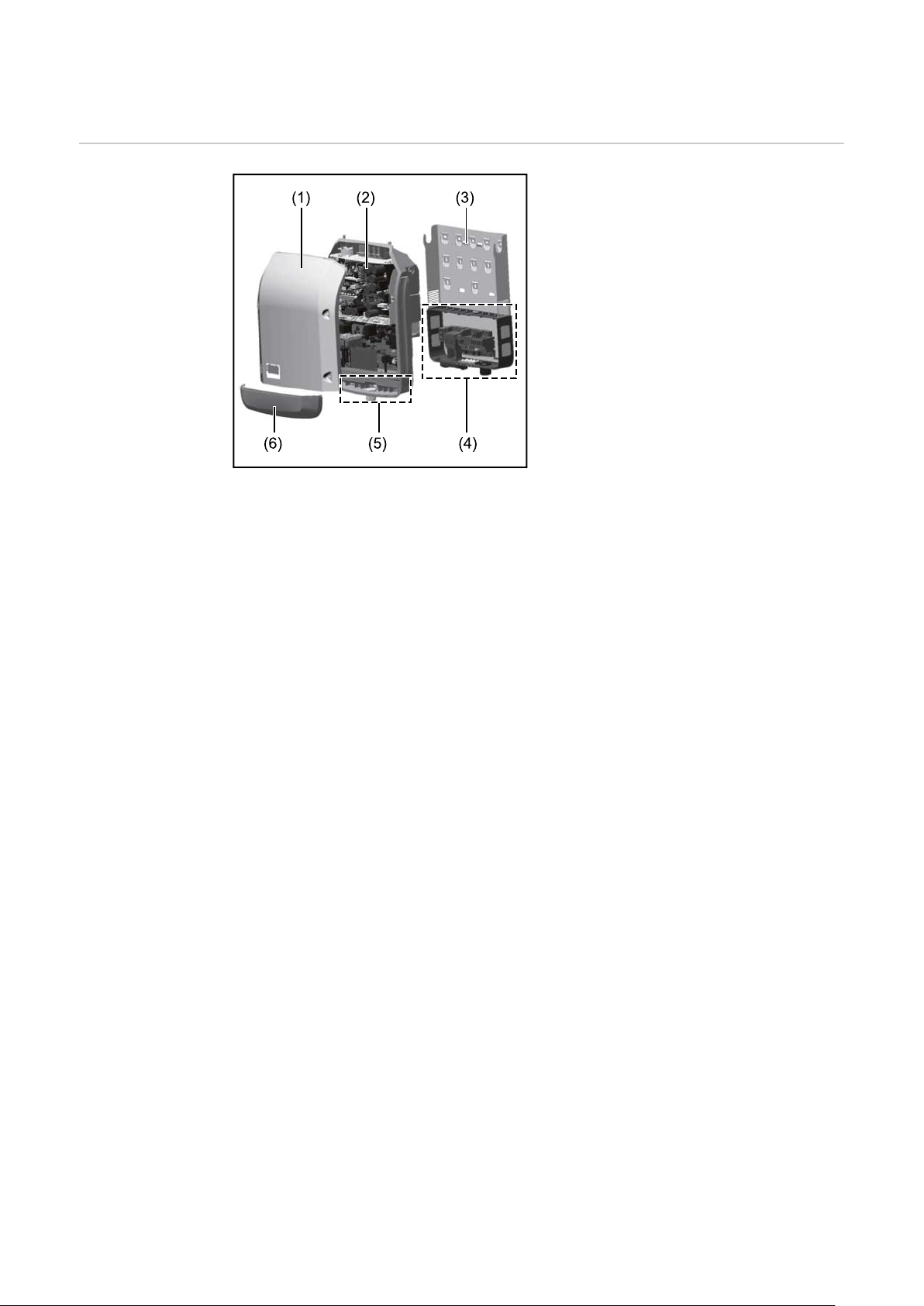
In generale
Concezione
dell'apparecchio
Struttura dell'apparecchio:
(1) Copertura del corpo esterno
(2) Inverter
(3) Supporto da parete
(4) Scatola dei collegamenti, incl.
interruttore CC principale
(5) Scatola di comunicazione dati
(6) Copertura della scatola di
comunicazione dati
L'inverter trasforma la corrente continua generata dai moduli solari in corrente alternata, che viene alimentata in
sincrono con la tensione di rete nella
rete elettrica pubblica.
L'inverter è stato concepito esclusivamente per essere utilizzato in impianti fotovoltaici collegati alla rete; la produzione di corrente indipendente dalla rete pubblica non è possibile.
La struttura e il funzionamento dell'inverter ne assicurano la massima sicurezza
in fase di montaggio e di esercizio.
L'inverter monitora automaticamente la rete elettrica pubblica. In caso di comportamenti di rete anomali, l'inverter cessa immediatamente di funzionare e interrompe l'alimentazione della rete elettrica (ad es. in presenza di interruzioni di
rete, ecc.).
La rete viene monitorata mediante il monitoraggio della tensione, della frequenza
e dei comportamenti a isola.
Il funzionamento dell'inverter è completamente automatico. L'inverter inizia a
monitorare la rete non appena, dopo il sorgere del sole, è disponibile energia sufficiente prodotta dai moduli solari. In presenza di irraggiamento solare sufficiente, l'inverter procede al funzionamento con alimentazione di rete.
Inoltre, funziona in modo tale da trarre la massima potenza possibile dai moduli
solari.
Non appena l'energia offerta per l'alimentazione di rete diventa insufficiente, l'inverter scollega completamente l'elettronica di potenza dalla rete e sospende il
funzionamento. Tutte le impostazioni e i dati salvati restano memorizzati.
Se l'apparecchio si surriscalda, interviene il sistema di autoprotezione dell'inverter che riduce automaticamente la potenza di uscita attuale.
Alla base del surriscaldamento dell'apparecchio possono esservi una temperatura ambiente elevata o un'asportazione di calore insufficiente (ad es. installazione all'interno di quadri elettrici privi di un'adeguata asportazione di calore).
Fronius Eco non è dotato di convertitore ausiliario interno. Questo si traduce in
limitazioni nella scelta dei moduli e delle stringhe. La tensione di entrata CC minima (UDC
disponibile un dispositivo altamente ottimizzato.
) dipende dalla tensione di rete. Per l'applicazione giusta è tuttavia
min
68
Page 69
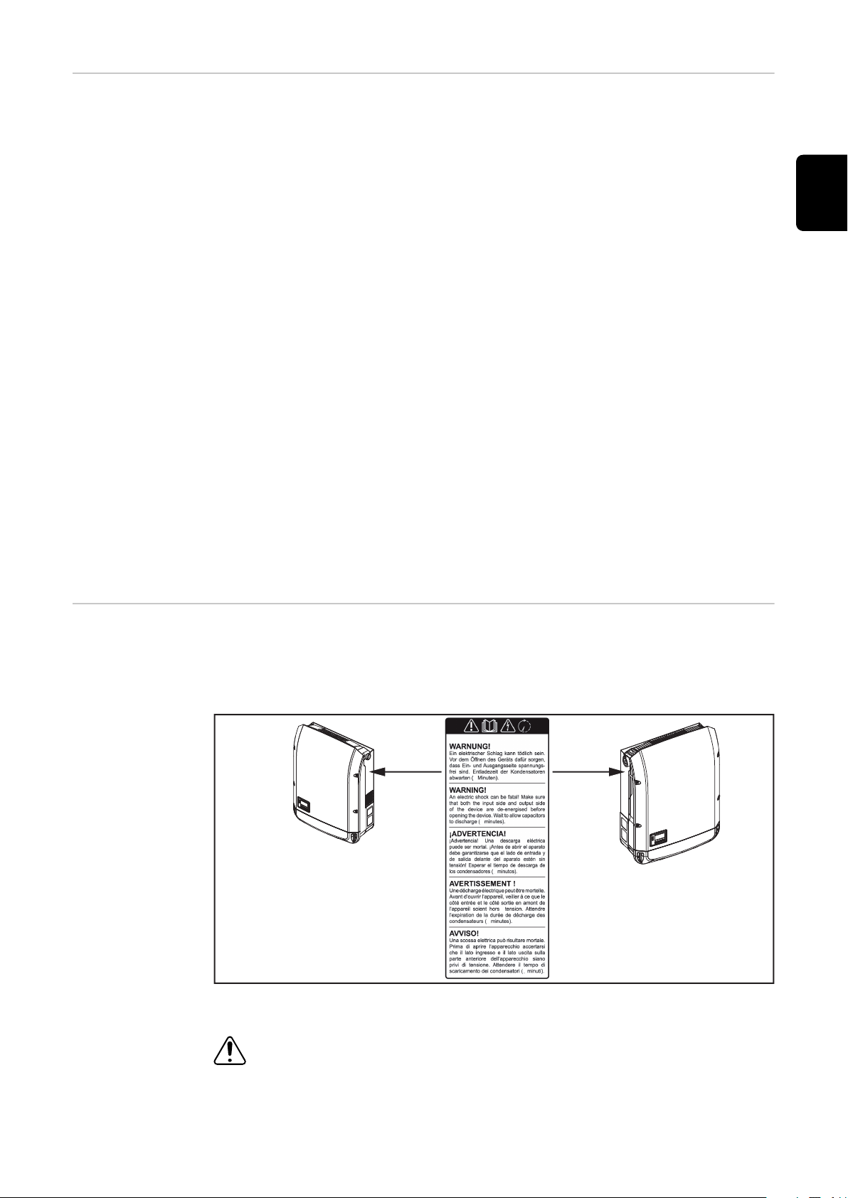
Uso prescritto L'inverter è destinato esclusivamente alla trasformazione della corrente continua
Fronius Symo
3.0-3-S / 3.7-3-S / 4.5-3-S
3.0-3-M / 3.7-3-M / 4.5-3-M
5.0-3-M / 6.0-3-M / 7.0-3-M
8.2-3-M
Fronius Symo
10.0-3-M / 12.5-3-M / 15.0-3-M
17.5-3-M / 20.0-3-M
Fronius Eco
25.0-3-S / 27.0-3-S
5
5
5
5
5
generata dai moduli solari in corrente alternata da alimentare nella rete elettrica
pubblica.
L'uso non prescritto comprende:
qualunque altro tipo d'uso che esuli da quello prescritto
-
adattamenti all'inverter non espressamente consigliati da Fronius
-
installazione di componenti non espressamente consigliati o distribuiti da
-
Fronius.
Il produttore non si assume alcuna responsabilità per gli eventuali danni che potrebbero derivarne.
Decadono inoltre tutti i diritti di garanzia.
L'uso prescritto comprende anche
la lettura integrale e l'osservanza scrupolosa di tutte le avvertenze, comprese
-
quelle relative alla sicurezza e ai possibili pericoli, contenute nelle istruzioni
per l'uso e nelle istruzioni d'installazione
l'esecuzione dei lavori di manutenzione
-
l'esecuzione del montaggio conformemente alle istruzioni d'installazione.
-
Durante l'installazione dell'impianto fotovoltaico, assicurarsi che il funzionamento di tutti i componenti avvenga esclusivamente entro la gamma consentita.
Tenere in considerazione tutte le misure consigliate dal produttore dei moduli
solari per preservare le caratteristiche dei moduli.
IT
Avvertenze riportate sull'apparecchio
Tenere in considerazione le disposizioni del gestore della rete relativamente all'alimentazione di rete e ai metodi di collegamento.
Sopra e all'interno dell'inverter sono riportati avvertenze e simboli di sicurezza
che non devono essere rimossi né sovrascritti. Le avvertenze e i simboli riportano
avvertimenti sul cattivo uso dell'apparecchio, da cui potrebbero risultare gravi lesioni personali e danni materiali.
Simboli di sicurezza:
Pericolo di gravi lesioni personali e danni materiali dovuto al cattivo uso
dell'apparecchio.
69
Page 70
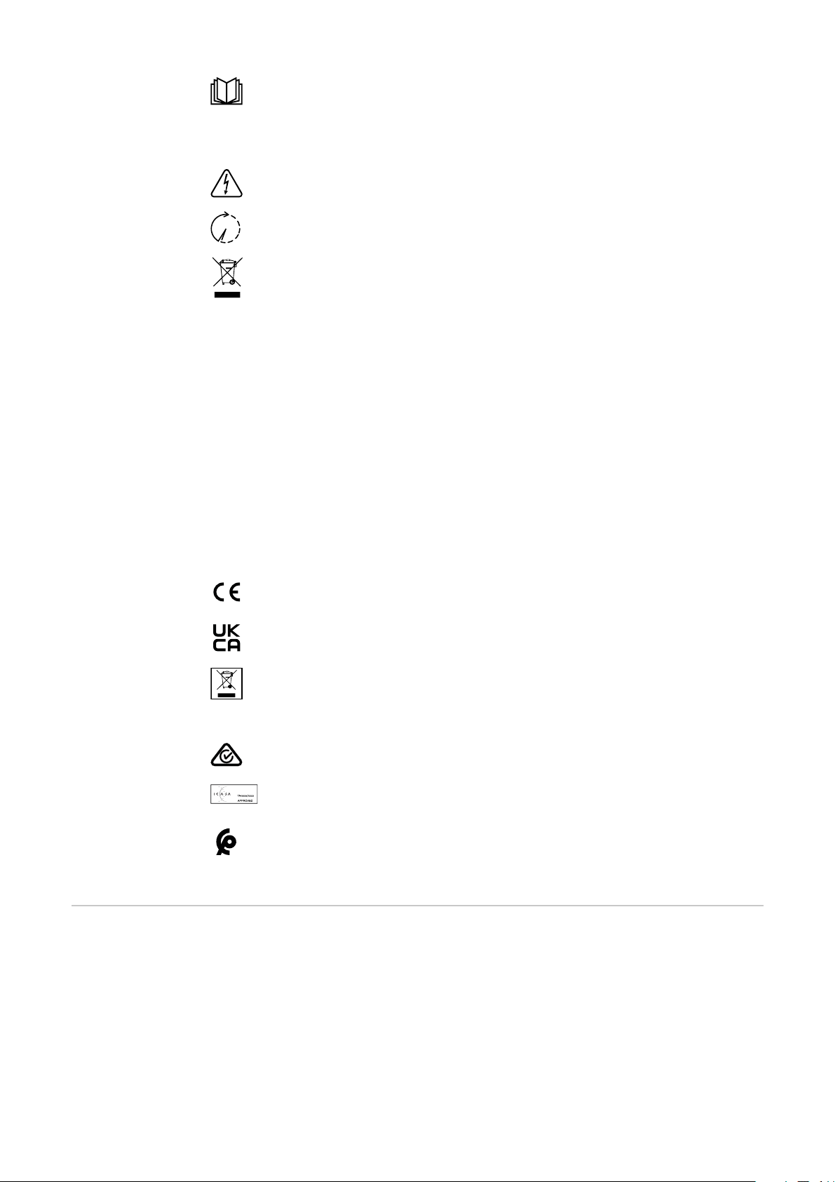
Utilizzare le funzioni descritte solo dopo aver letto integralmente e
compreso i seguenti documenti:
le presenti istruzioni per l'uso
-
tutte le istruzioni per l'uso dei componenti del sistema dell'impianto
-
fotovoltaico, in particolare le norme di sicurezza.
Tensione elettrica pericolosa.
Attendere il tempo di scaricamento dei condensatori!
Conformemente alla Direttiva Europea 2012/19/UE relativa ai rifiuti di
apparecchiature elettriche ed elettroniche e alla rispettiva applicazione
nell'ordinamento giuridico nazionale, gli apparecchi elettrici usati
devono essere raccolti separatamente e recuperati in modo compatibile
con l'ambiente. Provvedere alla restituzione dell'apparecchio usato
presso il proprio distributore, oppure informarsi sull'eventuale presenza
di un centro di raccolta e smaltimento autorizzato nella propria zona. La
mancata osservanza di questa direttiva UE può avere ripercussioni potenzialmente dannose sull'ambiente e sulla salute!
Testo delle avvertenze:
AVVISO!
Una scossa elettrica può risultare mortale. Prima di aprire l'apparecchio accertarsi che il lato ingresso e il lato uscita siano privi di tensione. Attendere il tempo
di scaricamento dei condensatori (5 minuti).
Controllo dell'inverter tramite
DRM (Demand
Response
Modes)
Simboli sulla targhetta:
Marcatura CE: conferma la conformità alle direttive e ai regolamenti UE
applicabili.
Marcatura UKCA: conferma la conformità alle direttive e ai regolamenti
applicabili nel Regno Unito.
Marcatura RAEE: i rifiuti di apparecchiature elettriche ed elettroniche
devono essere raccolti separatamente e riciclati in modo compatibile
con l'ambiente conformemente alla Direttiva Europea e alla legge
nazionale applicabile.
Marcatura RCM: testato secondo i requisiti validi in Australia e Nuova
Zelanda.
Marcatura ICASA: testato secondo i requisiti della Independent
Communications Authority del Sudafrica.
Marcatura CMIM: testato secondo i requisiti di IMANOR per i
regolamenti di importazione e la conformità alle norme del Marocco.
IMPORTANTE! Per controllare l'inverter tramite DRM occorre integrarvi un'interfaccia Fronius DRM (codice articolo 4,240,005).
Il montaggio e l'installazione sono descritti nelle istruzioni d'installazione
dell'interfaccia Fronius DRM. Le istruzioni d'installazione dell'interfaccia Fronius DRM sono disponibili sul sito Internet di Fronius:
70
Page 71
http://www.fronius.com/QR-link/4204102292 (documento
disponibile in inglese)
IT
Fusibili delle
stringhe
PERICOLO!
Una scossa elettrica può risultare mortale.
Pericolo derivante dalla tensione presente sui portafusibili. I portafusibili sono
sotto tensione se sul collegamento CC dell'inverter è presente tensione, anche se
l'interruttore CC è disattivato. Prima di eseguire qualsiasi lavoro sul portafusibile
dell'inverter, togliere la tensione dal lato CC.
Utilizzando fusibili delle stringhe in Fronius Eco, i moduli solari vengono ulteriormente protetti.
Per la protezione dei moduli solari sono determinanti la corrente di corto circuito
ISC e l'indicazione del valore massimo del fusibile della stringa in serie (ad es.
"Maximum Series Fuse Rating") riportata nella scheda tecnica del rispettivo modulo solare.
Il valore massimo del fusibile della stringa per morsetto è 20 A.
La corrente MPP (corrente nominale, corrente di esercizio) I
massima è 15 A
max
per stringa.
Se si collegano tre stringhe, si devono utilizzare le stringhe 1.1, 2.1, 2.3.
Se si devono collegare quattro stringhe, occorre usare le stringhe 1.1, 1.2, 2.1, 2.2.
Se l'inverter viene messo in funzione con un box di raggruppamento delle
stringhe esterno, occorre utilizzare un DC Connector Kit (codice articolo:
4,251,015). In questo caso i moduli solari vengono protetti esternamente nel box
di raggruppamento delle stringhe e all'interno dell'inverter vanno utilizzate le viti
metalliche.
Occorre rispettare le disposizioni nazionali relative alla protezione. Spetta all'installatore elettrico scegliere i fusibili delle stringhe giusti.
AVVERTENZA!
Per evitare il rischio di incendi, sostituire i fusibili difettosi solo con fusibili nuovi
ed equivalenti.
L'inverter viene consegnato in opzione con i seguenti fusibili:
6 fusibili delle stringhe da 15 A sull'ingresso CC+ e 6 viti metalliche sull'in-
-
gresso CC-.
12 viti metalliche
-
71
Page 72
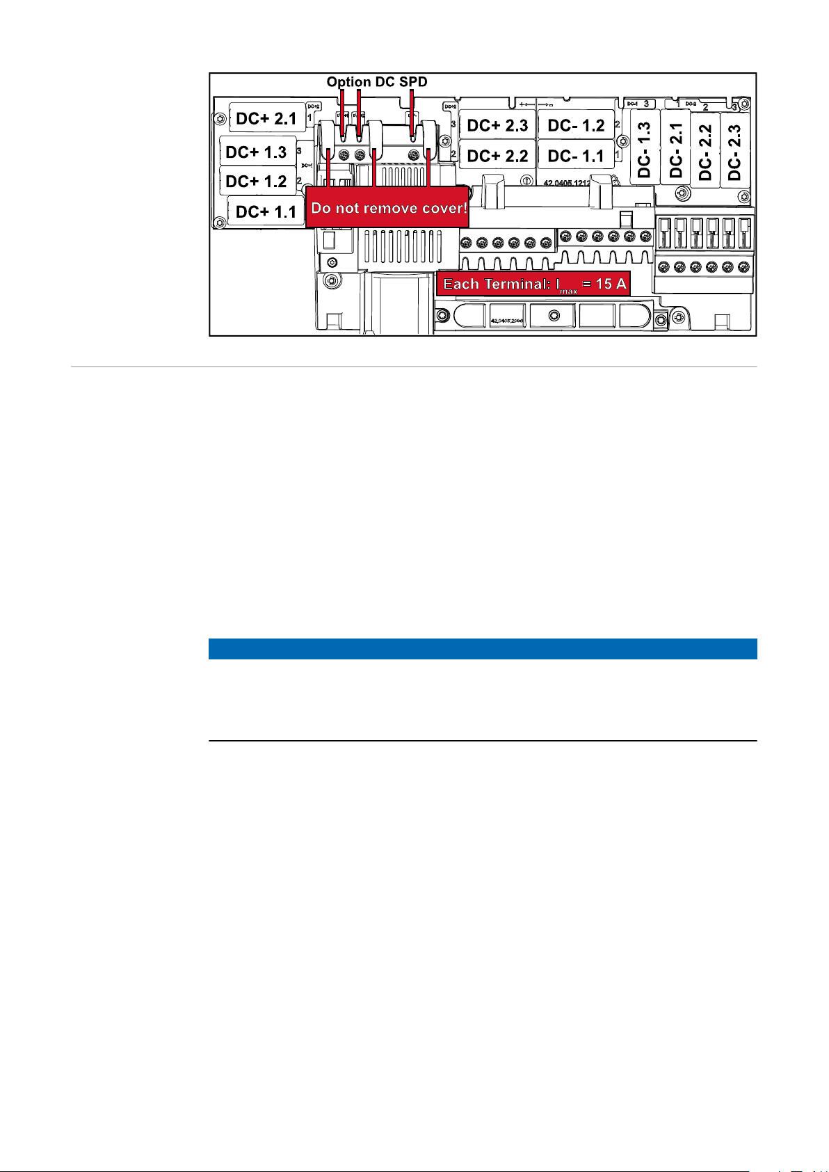
Criteri per la
scelta corretta
dei fusibili delle
stringhe
Per evitare che il fusibile scatti anzitempo durante il normale funzionamento,
quando si proteggono le stringhe dei moduli solari, si consiglia di soddisfare i
seguenti criteri per ogni stringa di moduli solari:
IN > 1,5 x I
-
VN >/= tensione di funzionamento a vuoto max. del generatore FV
-
Dimensioni dei fusibili: diametro 10 x 38 mm
-
SC
I
N
I
SC
Corrente nominale del fusibile
Corrente di corto circuito in condizioni di test standard (STC) conform-
emente alla scheda tecnica dei moduli solari
V
Tensione nominale del fusibile
N
AVVERTENZA!
Il valore di corrente nominale del fusibile non deve superare la protezione
massima specificata nella scheda tecnica del produttore dei moduli solari.
Se la protezione massima non è specificata, contattare il produttore dei moduli
solari.
72
Page 73
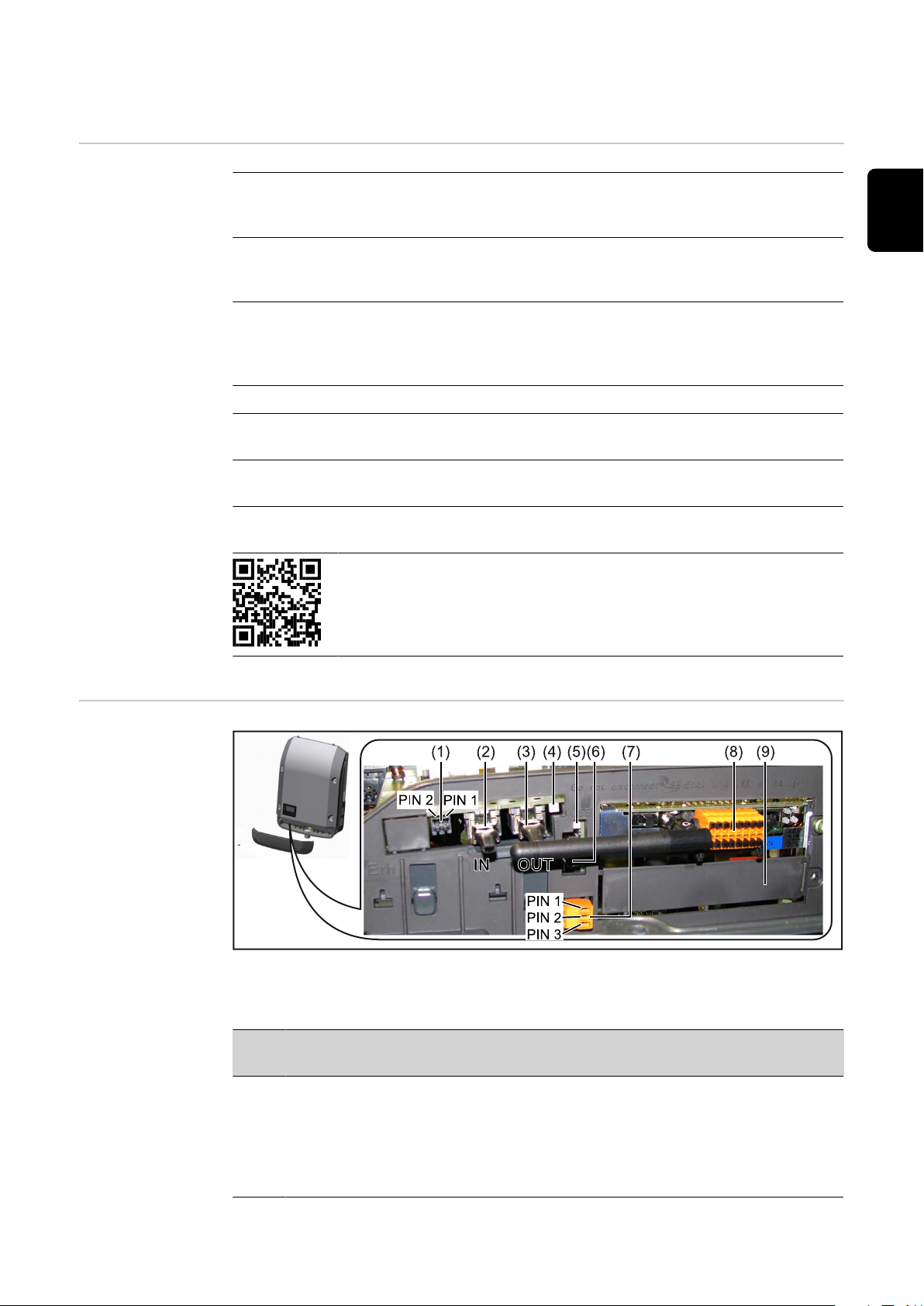
Comunicazione dati e Fronius Solar Net
Fronius Solar
Net e connessione dati
Per consentire l'utilizzo personalizzato delle estensioni del sistema, Fronius ha
sviluppato Fronius Solar Net. Fronius Solar Net è una rete dati che consente la
connessione di più inverter con le estensioni del sistema.
Fronius Solar Net è un sistema bus con topologia ad anello. Per la comunicazione di uno o più inverter connessi all'interno della Fronius Solar Net con
un'estensione del sistema è sufficiente un cavo adatto.
Per definire ogni inverter all'interno della Fronius Solar Net in modo univoco,
assegnare un codice personalizzato anche ai vari inverter.
Assegnare il codice personalizzato come descritto al paragrafo "Voce di menu
SETUP".
Fronius Solar Net riconosce automaticamente le diverse estensioni del sistema.
Per distinguere tra più estensioni del sistema identiche, assegnare a ognuna di
esse un codice personalizzato.
Per maggiori informazioni sulle varie estensioni del sistema, consultare le
rispettive istruzioni per l'uso o il sito Internet http://www.fronius.com.
Per ulteriori informazioni sul cablaggio dei componenti Fronius DATCOM,
vedere:
→ http://www.fronius.com/QR-link/4204101938.
IT
Scatola di comunicazione dati
A seconda della versione, l'inverter può essere dotato della scheda a innesto
Fronius Datamanager (8).
Num
. Denominazione
(1) Interfaccia di corrente multifunzione commutabile
Per una descrizione più dettagliata, vedere il successivo paragrafo
"Descrizione dell'interfaccia di corrente multifunzione".
Per il collegamento all'interfaccia di corrente multifunzione utilizzare la
spina di accoppiamento a 2 poli compresa nella fornitura dell'inverter.
73
Page 74

Num
. Denominazione
(2)
(3)
(4) LED "Fronius Solar Net"
(5) LED "Trasmissione dei dati"
(6) Porta USB A
Connettore IN Fronius Solar Net/Interface Protocol
Connettore OUT Fronius Solar Net/Interface Protocol
Ingresso e uscita Fronius Solar Net/Interface Protocol per la connessione con altri componenti DATCOM (ad es. inverter, Fronius Sensor
Box, ecc.).
In caso di collegamento in rete di più componenti DATCOM, a ogni connettore IN o OUT libero di un componente DATCOM occorre collegare
uno spinotto terminale.
Nella fornitura degli inverter dotati della scheda a innesto Fronius
Datamanager sono compresi 2 spine di chiusura.
Indica se l'alimentazione elettrica della Fronius Solar Net è disponibile.
Lampeggia durante l'accesso alla chiavetta USB. La chiavetta USB deve
restare inserita per tutta la durata dell'operazione.
Per collegare una chiavetta USB di dimensioni massime
65 x 30 mm (2,6 x 2,1 in.).
La chiavetta USB, laddove sia stata collegata, può fungere da Datalogger per il relativo inverter. La chiavetta USB non è compresa nella fornitura dell'inverter.
(7) Contatto di commutazione a potenziale zero (relè) con spina di accop-
piamento
Max. 250 V CA/4 A CA
Max. 30 V CC/1 A CC
Max. 1,5 mm² (AWG 16) di sezione del cavo
Pin 1 = contatto di chiusura (Normally Open)
Pin 2 = vertice (Common)
Pin 3 = contatto di chiusura (Normally Closed)
Per una descrizione più dettagliata, vedere il paragrafo "Voci del menu
di setup/Relè".
Per il collegamento al contatto di commutazione a potenziale zero
utilizzare la spina di accoppiamento compresa nella fornitura dell'inverter.
(8) Fronius Datamanager con antenna WLAN
o
copertura dello slot per schede opzionali
(9) Copertura dello slot per schede opzionali
Spiegazione del
LED "Fronius
Solar Net"
74
LED "Fronius Solar Net" acceso:
alimentazione elettrica per la comunicazione dati all'interno della Fronius Solar
Net/Interface Protocol funzionante.
LED "Fronius Solar Net" lampeggiante brevemente ogni 5 secondi:
errore durante la comunicazione dati all'interno della Fronius Solar Net.
Page 75

Sovracorrente (flusso di corrente > 3 A, ad es. a causa di un corto circuito
1 2
3
IN
OUT
°C
W/m²
m/s
IN
OUT
IN
OUT
Sensor Box
WLAN
* Fronius Datamanager
*
IN
OUT
-
all'interno dell'anello della Fronius Solar Net).
Sottotensione (nessun corto circuito, tensione all'interno della Fronius Solar
-
Net < 6,5 V, ad es. se all'interno della Fronius Solar Net è presente un numero eccessivo di componenti DATCOM e l'alimentazione elettrica è insufficiente).
In questo caso occorre predisporre un'alimentazione elettrica aggiuntiva dei
componenti Fronius DATCOM mediante alimentatore esterno
(43,0001,1194) su uno dei componenti Fronius DATCOM.
Per rilevare la presenza di sottotensione controllare, se necessario, la
presenza di errori negli altri componenti Fronius DATCOM.
A seguito di uno spegnimento causato da sovracorrente o sottotensione, l'inverter tenta di ripristinare l'alimentazione elettrica all'interno della Fronius Solar Net
ogni 5 secondi, finché l'errore è presente.
Se l'errore viene eliminato, l'alimentazione di corrente della Fronius Solar Net
viene ripristinata entro 5 secondi.
Esempio Registrazione e archiviazione dei dati dell'inverter e del sensore mediante Fronius
Datamanager e Fronius Sensor Box:
IT
Rete dati con 3 inverter e una Fronius Sensor Box:
- Inverter 1 con Fronius Datamanager
- Inverter 2 e 3 senza Fronius Datamanager!
La comunicazione esterna (Fronius Solar Net) avviene nell'inverter attraverso la
scatola di comunicazione dati. La scatola di comunicazione dati comprende due
interfacce RS 422 come ingresso e uscita. Il collegamento avviene per mezzo di
spine RJ45.
IMPORTANTE! Dato che Fronius Datamanager funge da Datalogger, nell'anello
della Fronius Solar Net non devono esservi altri Datalogger.
Per ogni anello della Fronius Solar Net deve esservi un solo Fronius Datamanager!
Fronius Symo 3-10 kW: smontare tutti gli altri Fronius Datamanager e chiudere
lo slot per schede opzionali libero con la copertura cieca (42,0405,2020)
opzionale disponibile presso Fronius, oppure utilizzare un inverter non dotato di
Fronius Datamanager (versione light).
Fronius Symo 10-20 kW, Fronius Eco: smontare tutti gli altri Fronius Datamanager e chiudere lo slot per schede opzionali libero sostituendo la copertura (codice articolo 42,0405,2094), oppure utilizzare un inverter non dotato di Fronius
Datamanager (versione light).
= Spinotto terminale
75
Page 76

Descrizione
dell'interfaccia
di corrente multifunzione
All'interfaccia di corrente multifunzione è possibile collegare diverse varianti di
configurazione circuitale. Queste però non possono essere utilizzate contemporaneamente. Se, ad esempio, all'interfaccia di corrente multifunzione è stato collegato un contatore S0, non è possibile collegare alcun contatto di segnale per la
protezione contro le sovratensioni (e viceversa).
Pin 1 = ingresso di misurazione: max. 20 mA, resistore di precisione 100 Ohm (carico)
Pin 2 = corrente di corto circuito max. 15 mA, tensione di funzionamento a vuoto
max. 16 V CC o GND
Configurazione circuitale, variante 1: Contatto di segnale per la protezione contro le sovratensioni
L'opzione DC SPD (protezione contro le sovratensioni) visualizza sul display, a
seconda dell'impostazione nel menu BASE (sottomenu "Ingr. segnale"), un avviso
o un errore. Per ulteriori informazioni sull'opzione DC SPD , consultare le istruzioni d'installazione.
Configurazione circuitale, variante 2: Contatore S0
È possibile collegare direttamente all'inverter un contatore per il rilevamento
dell'autoconsumo per ogni S0. Tale contatore S0 può essere posizionato sul
punto di alimentazione oppure nel ramo di consumo.
IMPORTANTE! Il collegamento di un contatore S0 all'inverter può richiedere
l'aggiornamento del firmware dell'inverter stesso.
Il contatore S0 deve essere conforme alla norma IEC62053-31 Classe B
Frequenza impulsi max. consigliata del contatore S0:
Potenza FV kWp [kW] Frequenza impulsi max. per ogni kWp
30 1000
20 2000
10 5000
≤ 5,5 10000
Con questo strumento, la riduzione dinamica della potenza può essere effettuata
in due modi:
Riduzione dinamica della potenza mediante un inverter
-
Per ulteriori informazioni si veda il capitolo Riduzione dinamica della po-
tenza per mezzo di un inverter a pagina 77
Riduzione dinamica della potenza con Datamanager 2.0
-
Per ulteriori informazioni, vedere: manuals.fronius.com/html/4204260191/
#0_m_0000017472
76
Page 77

Riduzione dinamica della potenza per mezzo
di un inverter
Le aziende energetiche o i gestori di rete possono prescrivere limiti di immissione
per un inverter. La riduzione dinamica della potenza tiene conto dell'autoconsumo domestico prima di ridurre la potenza dell’inverter:
È possibile collegare direttamente all'inverter un contatore per il rilevamento
dell'autoconsumo per ogni S0. Vedere il capitolo Descrizione dell'interfaccia di
corrente multifunzione a pagina 76
Un limite di immissione può essere impostato nel menu Base alla voce Ingresso
segnale - Contatore S0. Vedere il capitolo Voci del menu BASE a pagina 106.
Opzioni di impostazione misuratore S0:
Limite di immissione in rete
-
Campo per l'immissione della potenza massima di alimentazione di rete in W.
Se questo valore viene superato, l'inverter si regola fino al valore impostato
entro il tempo richiesto dagli standard e dalle normative nazionali.
Impulsi per kWh
-
Campo per l'inserimento degli impulsi per kWh del contatore S0.
Con questa configurazione è possibile zero alimentazione di rete.
Quando si utilizza il contatore S0 e la riduzione di potenza per mezzo di un inverter, il contatore S0 deve essere installato nel ramo di consumo.
IT
Contatore S0 nel ramo di consumo
Se la riduzione dinamica della potenza viene successivamente configurata con
Datamanager 2.0 (interfaccia utente dell'inverter - menu EVU Editor - Riduzione
dinamica della potenza), la riduzione dinamica della potenza deve essere disattivata tramite l'inverter (display dell'inverter - menu Base - Ingresso segnale Misuratore S0).
77
Page 78

Fronius Datamanager 2.0
(5)
(1)
(6)(7)
(10) (8)(9)
(4)
(2)
(3)
Elementi di
comando, attacchi e spie di
Fronius
Datamanager 2.0
N. Funzione
(1) Interruttore IP
Per passare da un indirizzo IP a un altro:
Posizione "A"
Indirizzo IP predefinito e apertura del punto di accesso WLAN.
Per la connessione diretta con un PC tramite rete LAN, Fronius
Datamanager 2.0 funziona con l'indirizzo IP fisso "169.254.0.180".
Se l'interruttore IP è posizionato su "A", viene aperto anche un
punto di accesso per la connessione WLAN diretta a Fronius
Datamanager 2.0.
Dati di accesso per questo punto di accesso:
Nome della rete: FRONIUS_240.XXXXXX
Chiave: 12345678
È possibile accedere a Fronius Datamanager 2.0:
con il nome DNS "http://datamanager"
-
con l'indirizzo IP "169.254.0.180" per l'interfaccia LAN
-
con l'indirizzo IP "192.168.250.181" per il punto di accesso
-
WLAN.
Posizione "B"
Indirizzo IP assegnato.
78
Fronius Datamanager 2.0 funziona con un indirizzo IP assegnato
(impostazione di fabbrica: dinamico (DHCP)).
L'indirizzo IP può essere impostato nella pagina Web di Fronius
Datamanager 2.0.
Page 79

N. Funzione
(2) LED WLAN
Lampeggiante con luce verde: Fronius Datamanager 2.0 in modalità
-
di servizio
(l'interruttore IP sulla scheda a innesto Fronius Datamanager 2.0 è
posizionato su "A" oppure la modalità di servizio è stata attivata
tramite il display dell'inverter; il punto di accesso WLAN è aperto).
Acceso con luce verde: connessione WLAN presente.
-
Lampeggiante con luce verde/rossa alternata: tempo di apertura del
-
punto di accesso WLAN dopo l'attivazione (1 ora) superato.
Acceso con luce rossa: connessione WLAN assente.
-
Lampeggiante con luce rossa: connessione WLAN errata.
-
Spento: Fronius Datamanager 2.0 in modalità slave.
-
(3) LED Connessione Fronius Solar.web
Acceso con luce verde: connessione a Fronius Solar.web presente.
-
Acceso con luce rossa: connessione a Fronius Solar.web necessaria,
-
ma assente.
Spento: connessione a Fronius Solar.web non necessaria.
-
(4) LED Alimentazione
Acceso con luce verde: alimentazione elettrica erogata dalla Froni-
-
us Solar Net sufficiente; Fronius Datamanager 2.0 pronto per l'uso.
Spento: alimentazione elettrica erogata dalla Fronius Solar Net in-
-
sufficiente o non disponibile; necessaria alimentazione elettrica esterna
oppure
Fronius Datamanager 2.0 in modalità slave.
Lampeggiante con luce rossa: aggiornamento in corso.
-
IT
IMPORTANTE! Non interrompere l'alimentazione elettrica durante
l'aggiornamento.
Acceso con luce rossa: aggiornamento non riuscito.
-
(5) LED Connessione
Acceso con luce verde: connessione all'interno della Fronius Solar
-
Net presente.
Acceso con luce rossa: connessione all'interno della Fronius Solar
-
Net interrotta.
Spento: Fronius Datamanager 2.0 in modalità slave.
-
(6) Porta LAN
Interfaccia Ethernet contrassegnata con colore blu; per il collegamento
del cavo Ethernet.
79
Page 80
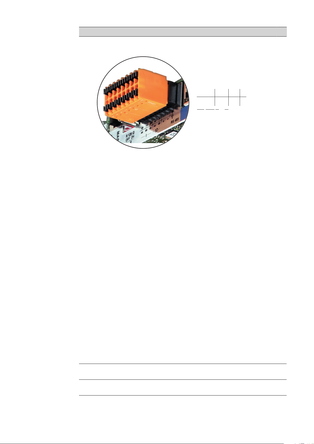
N. Funzione
D-
-
-
1
3
5
7
9
D+
+
+
0
2
4
6
8
I IO RS485
(7) I/O
Ingressi e uscite digitali.
Modbus RTU 2 fili (RS485):
D- Dati Modbus D+ Dati Modbus +
Alimentazione int./est.
- GND
+ U
int/Uext
Uscita della tensione interna 12,8 V
oppure
ingresso per una tensione d'alimentazione esterna
> 12,8-24 V CC (+ 20%)
Ingressi digitali: 0-3, 4-9
Livello di tensione: low = da min. 0V a max. 1,8V; high = da min. 3V a
max. 24V CC (20%).
Correnti di entrata: a seconda della tensione di entrata; resistenza di entrata = 46 kOhm.
Uscite digitali: 0-3
Potere di apertura con alimentazione tramite la scheda a innesto Fronius Datamanager 2.0: 3,2 W complessivamente per tutte e 4 le uscite digitali.
Potere di apertura con alimentazione tramite un alimentatore esterno
da min. 12,8 a max. 24 V CC (+20%), collegato a Uint/Uext e GND: 1 A,
12,8-24 V CC (a seconda dell'alimentatore esterno) per ciascuna uscita
digitale.
80
Il collegamento alle I/O viene eseguito tramite la spina di accoppiamento compresa nella fornitura.
(8) Base dell'antenna
Per avvitare l'antenna WLAN.
Page 81
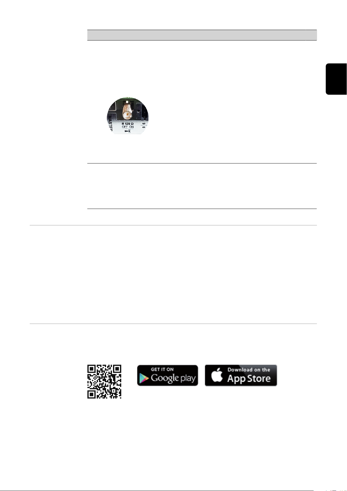
N. Funzione
(9) Terminazione interruttore Modbus (per Modbus RTU)
Terminazione bus interno con resistenza 120 ohm (sì/no).
Interruttore posizionato su "on": resistenza 120 ohm della terminazione
attiva.
Interruttore posizionato su "off": nessuna resistenza della terminazione
attiva.
IMPORTANTE! All'interno di un bus RS485, la resistenza della terminazione per il primo e l'ultimo apparecchio deve essere attiva.
(10) Interruttore master/slave Fronius Solar Net
Per passare dal funzionamento master a quello slave all'interno
dell'anello della Fronius Solar Net.
IMPORTANTE! Nel funzionamento slave tutti i LED sulla scheda a innesto Fronius Datamanager 2.0 sono spenti.
IT
Fronius
Datamanager
durante la notte
o in caso di tensione CC insufficiente
Prima messa in
funzione
Il parametro Modalità notturna nella voce del menu di setup Impostazioni del
display è preimpostato di fabbrica su "OFF (disattiva)".
Per questa ragione Fronius Datamanager non è raggiungibile durante la notte o in
caso di tensione CC insufficiente.
Per attivare comunque Fronius Datamanager, disattivare e riattivare il lato CA
dell'inverter e premere un tasto funzione qualsiasi sul display dell'inverter entro
90 secondi.
Vedere anche il capitolo "Voci del menu di setup", "Impostaz. display" (Modalita
notturna).
L’app Fronius Solar.web consente di semplificare notevolmente la prima messa in
funzione di Fronius Datamanager 2.0. L’app Fronius Solar.start è disponibile nel
relativo App Store.
Per la prima messa in funzione di Fronius Datamanager 2.0
la scheda a innesto Fronius Datamanager 2.0 deve essere installata nell'in-
-
verter oppure
all'interno dell'anello della Fronius Solar Net deve esservi una Fronius
-
Datamanager Box 2.0.
81
Page 82
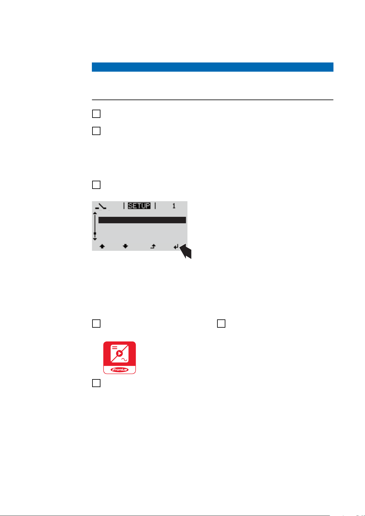
IMPORTANTE! Per stabilire la connessione a Fronius Datamanager 2.0 occorre
Stand by
WiFi Access Point
DATCOM
USB
Clock
selezionare "Ottieni automaticamente un indirizzo IP (DHCP)" per il relativo apparecchio terminale (ad es. computer portatile, tablet, ecc.).
AVVERTENZA!
Se all'interno dell’impianto fotovoltaico è presente un solo inverter, è possibile
saltare le operazioni 1 e 2 seguenti.
In questo caso la prima messa in funzione inizia con l'operazione 3.
Cablare l'inverter dotato di Fronius Datamanager 2.0 o Fronius Datamanager
1
Box 2.0 all'interno della Fronius Solar Net.
In caso di collegamento in rete di diversi inverter in Fronius SolarNet:
2
Posizionare correttamente l'interruttore master/slave Fronius Solar Net sulla
scheda a innesto Fronius Datamanager 2.0
un inverter dotato di Fronius Datamanager 2.0 = master
-
tutti gli altri inverter dotati di Fronius Datamanager 2.0 = slave (i LED
-
sulle schede a innesto Fronius Datamanager 2.0 sono spenti).
Commutare l'apparecchio nella modalità Servizio.
3
Attivare il WLAN Access Point dal menu di setup dell'inverter.
-
L'inverter crea il WLAN Access Point. Il WLAN Access Point resta aperto per 1
ora. Attivando il WLAN Access Point, l'interruttore "IP" su Fronius Datamanager
2.0 può essere lasciato nella posizione "B".
Installazione mediante l’app Solar.start
Scaricare l’app Fronius Sol-
4
ar.start.
Installazione mediante browser
Web
Collegare il dispositivo terminale
4
al WLAN Access Point
SSID = FRONIUS_240.xxxxx (5-8
cifre)
Cercare una rete con il nome
-
"FRONIUS_240.xxxxx".
Stabilire la connessione a
-
Eseguire l’app Fronius Solar.start
5
questa rete
Digitare la password
-
"12345678"
(Oppure connettere dispositivo
terminale e inverter mediante
cavo Ethernet.)
82
Page 83
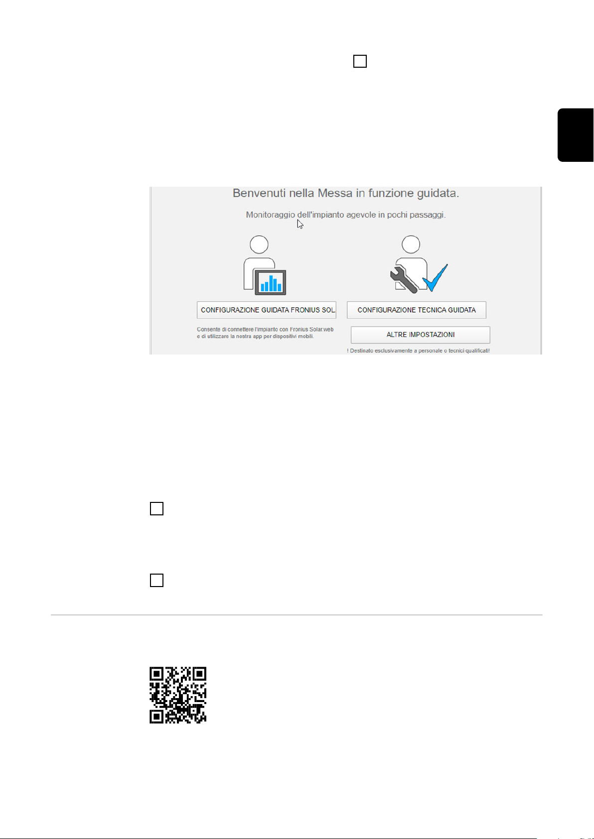
Nel browser, digitare:
5
"http://datamanager"
oppure
"192.168.250.181" (indirizzo IP
per la connessione WLAN)
oppure
"169.254.0.180" (indirizzo IP per
la connessione LAN).
Viene visualizzata la pagina iniziale di "Messa in funzione guidata".
IT
Ulteriori informazioni su Fronius
Datamanager 2.0
"Configurazione tecnica guidata" è prevista per gli installatori e contiene impostazioni specifiche relative alle norme. L'esecuzione di "Configurazione tecnica
guidata" è opzionale.
Se si esegue "Configurazione tecnica guidata", prendere assolutamente nota
della password di servizio assegnata. Questa password di servizio è necessaria
per impostare la voce di menu "Editor EVU".
Se non si esegue "Configurazione tecnica guidata", non è configurata alcuna impostazione predefinita per la riduzione della potenza.
È obbligatorio eseguire "Configurazione guidata Fronius Solar.web"!
Eseguire "Configurazione guidata Fronius Solar.web" e seguire le istruzioni.
6
Viene visualizzata la pagina iniziale di Fronius Solar.web
oppure
il sito Web di Fronius Datamanager 2.0.
All'occorrenza, eseguire "Configurazione tecnica guidata" e seguire le is-
7
truzioni.
Per ulteriori informazioni su Fronius Datamanager 2.0 e sulle altre opzioni per
la messa in funzione, consultare:
→ http://www.fronius.com/QR-link/4204260191IT.
83
Page 84
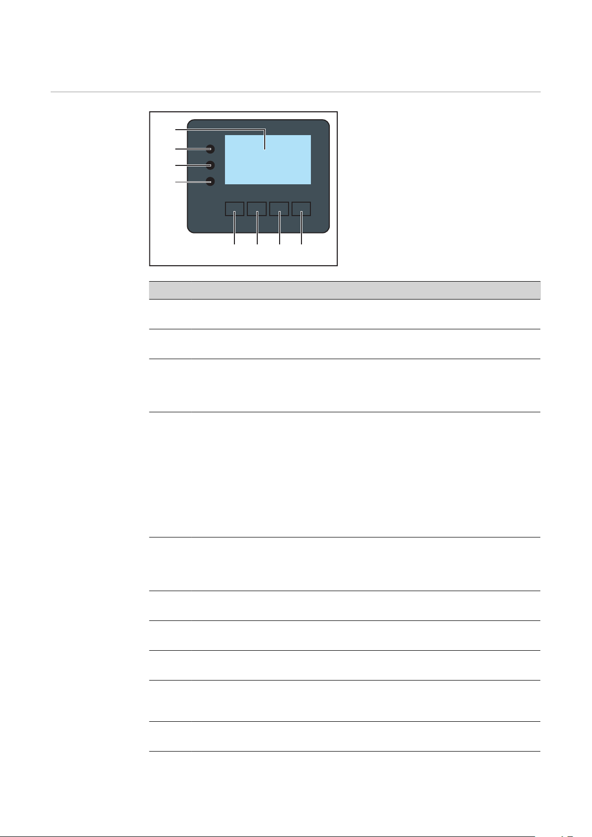
Elementi di comando e spie
(1)
(2)
(3)
(4)
(5) (6) (7) (8)
Elementi di
comando e spie
Num. Descrizione
(1) Display
Per visualizzare valori, impostazioni e menu.
LED di controllo e di stato
(2) Il LED Inizializzazione (rosso) si accende
durante la fase di inizializzazione all'avvio dell'inverter
-
se, all'avvio dell'inverter, nella fase di inizializzazione si verifica un
-
errore hardware permanente.
(3) Il LED Stato (arancione) si accende se
l'inverter, dopo la fase di inizializzazione, si trova nella fase di avvio
-
automatico o di autotest (non appena i moduli solari, dopo il
sorgere del sole, iniziano a erogare potenza sufficiente)
sul display dell'inverter vengono visualizzati messaggi di stato (co-
-
dici STATE)
l'inverter è stato azionato dal menu di setup nella modalità
-
standby (= disattivazione manuale del funzionamento con alimentazione di rete)
il software dell'inverter viene aggiornato.
-
(4) Il LED Funzionamento (verde) si accende
se l'impianto fotovoltaico, dopo la fase di avvio automatico dell'in-
-
verter, funziona senza problemi
fintanto che ha luogo il funzionamento con alimentazione di rete.
-
Tasti funzione, occupati da varie funzioni a seconda della selezione:
(5) Tasto "Sinistra/su"
Per navigare verso sinistra e verso l'alto.
84
(6) Tasto "Giù/destra"
Per navigare verso il basso e verso destra.
(7) Tasto "Menu/Esc"
Per passare a un altro livello di menu.
Per uscire dal menu di setup.
(8) Tasto "Enter"
Per confermare una selezione.
Page 85
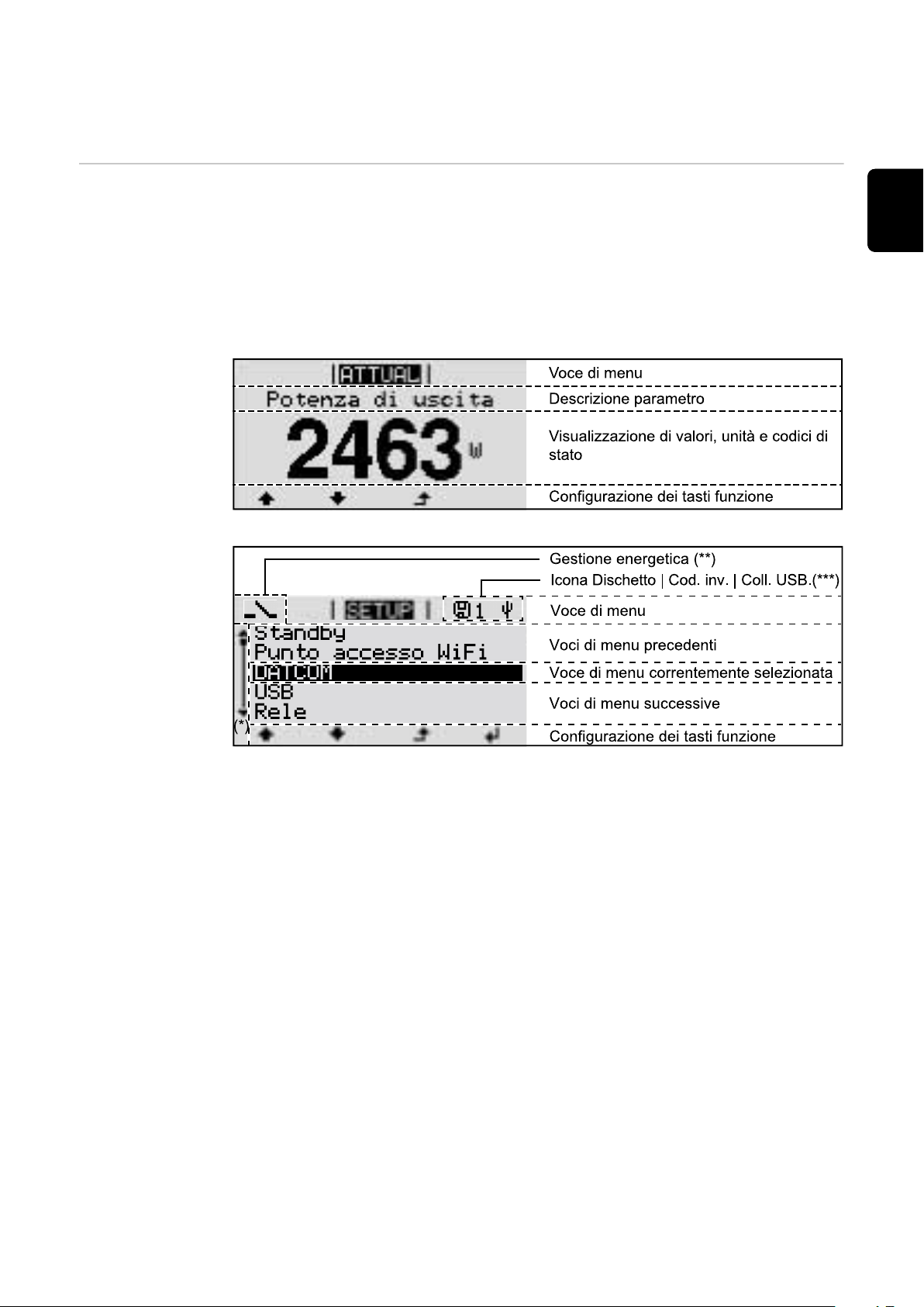
I tasti sono capacitivi, per cui l'umettazione con acqua può pregiudicarne il funzionamento. Per mantenere il funzionamento ottimale dei tasti, se necessario, asciugarli con un panno.
Display Il display è alimentato dalla tensione di rete CA. A seconda dell'impostazione
configurata nel menu di setup, è possibile rendere il display disponibile tutto il
giorno.
IMPORTANTE! Il display dell'inverter non è un apparecchio di misura tarato.
Una piccola variazione rispetto al contatore energetico dell'azienda di erogazione
dell'energia elettrica è sistematica. Il conteggio esatto dei dati con l'azienda di
erogazione dell'energia elettrica richiede quindi un contatore tarato.
Campi visualizzati sul display, modalità di visualizzazione
IT
Campi visualizzati sul display, modalità Setup
(*) Barra di scorrimento
(**) Quando la funzione "Gestione energetica" è attivata,
viene visualizzata la rispettiva icona.
(***) "N. inv." = codice DATCOM dell'inverter,
"Icona Dischetto" - viene visualizzata brevemente durante il salvataggio
dei valori impostati,
"Coll. USB" - compare se è stato collegato una chiavetta USB.
85
Page 86
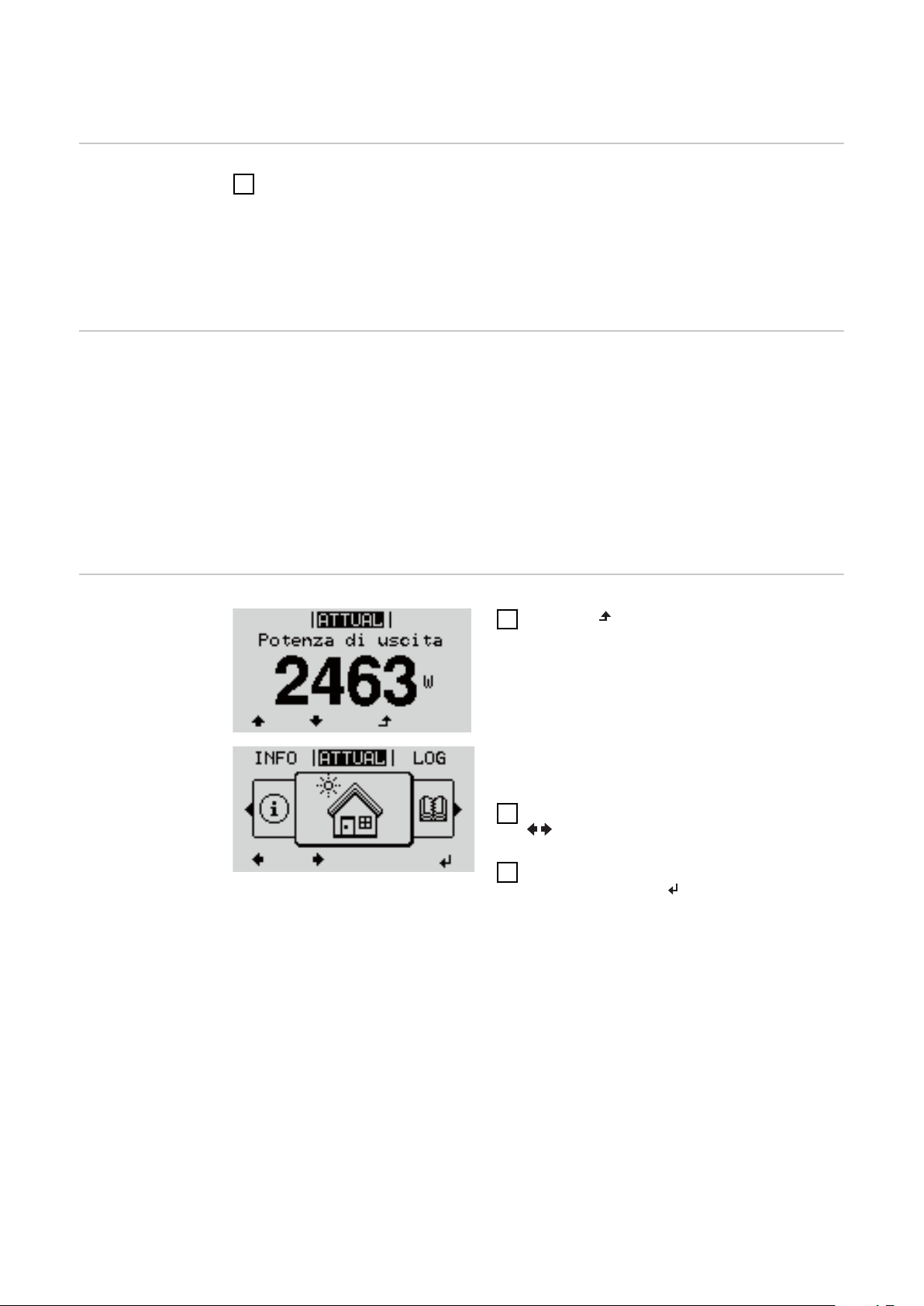
Navigazione nei livelli di menu
Attivazione
dell'illuminazione del
display
Disattivazione
automatica
dell'illuminazione del
display/passaggio alla voce di
menu "ATTUAL"
Richiamo del livello di menu
Premere un tasto qualsiasi.
1
L'illuminazione del display si attiva.
Nella voce di menu SETUP, in "Impostaz. display", è inoltre possibile impostare l'illuminazione del display costantemente accesa o costantemente
spenta.
Se non si preme alcun tasto per 2 minuti, l'illuminazione del display si spegne
automaticamente e l'inverter passa alla voce di menu "ATTUAL" (se l'illuminazione del display è impostata su "AUTO").
Il passaggio automatico alla voce di menu "ATTUAL" avviene da qualsiasi posizione all'interno del livello di menu, a meno che l'inverter non sia stato commutato
manualmente nella modalità di funzionamento in standby.
Dopo il passaggio automatico alla voce di menu "ATTUAL", viene visualizzata la
potenza correntemente alimentata.
1
Premere il tasto "Esc".
Il display passa al livello di menu.
Selezionare la voce di menu desiderata
2
con i tasti "sinistra" o "destra".
Richiamare la voce di menu desiderata
3
premendo il tasto .
Le voci del menu
ATTUAL
-
Visualizzazione dei valori correnti.
LOG
-
Dati registrati del giorno corrente, dell'anno di calendario corrente e dalla
prima messa in funzione dell'inverter.
GRAFIC
-
La curva caratteristica giornaliera rappresenta graficamente l'andamento
della potenza di uscita durante la giornata. L'asse del tempo si ridimensiona
automaticamente. Premere il tasto "Indietro" per chiudere la schermata.
SETUP
-
Menu di setup.
INFO
-
Informazioni relative all'apparecchio e al software.
86
Page 87
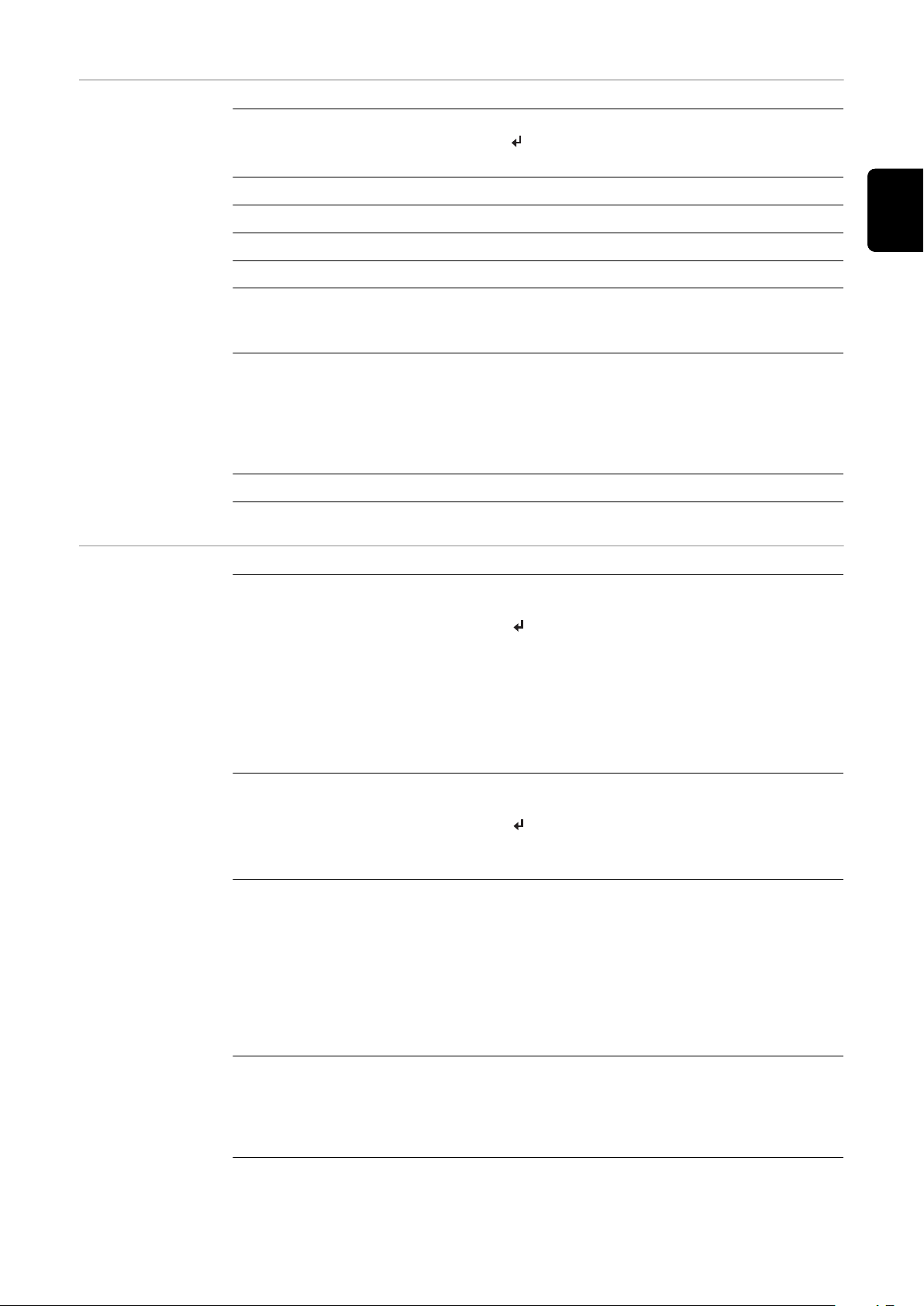
Valori visualizzati nella
voce di menu ATTUAL
Potenza di uscita (W) - a seconda del modello di apparecchio (MultiString),
dopo aver premuto il tasto "Enter", vengono visualizzate le singole potenze
di uscita per l'inseguitore MPP 1 e l'inseguitore MPP 2 (MPPT1 / MPPT2).
Potenza reattiva CA (VAr)
Tensione di rete (V)
Corrente di uscita (A)
Frequenza di rete (Hz)
Tensione mod. solari (V) - "U PV1" dell'inseguitore MPP 1 e "U PV2" dell'inse-
guitore MPP 2 (MPPT1 / MPPT2), se l'inseguitore MPP 2 è attivato (vedere
"Menu BASE" - "Voci del menu BASE").
Corrente mod. solari (A) - "I PV1" dell'inseguitore MPP 1 e "I PV2" dell'inseguitore MPP 2 (MPPT1 / MPPT2), se l'inseguitore MPP 2 è attivato (vedere
"Menu BASE" - "Voci del menu BASE").
Fronius Eco: viene visualizzata la corrente complessiva dei due canali di misurazione. Su Fronius Solar.web i due canali di misurazione vengono visualizzati
separatamente.
Ora / Data - ora e data sull'inverter o nell'anello della Fronius Solar Net.
IT
Valori visualizzati nella
voce di menu
LOG
Energia alimentata (kWh/MWh)
Energia alimentata nella rete durante il periodo considerato.
Dopo aver premuto il tasto "Enter", vengono visualizzate le singole potenze
di uscita dell'inseguitore MPP 1 e dell'inseguitore MPP 2 (MPPT1 / MPPT2), se
l'inseguitore MPP 2 è attivato (vedere "Menu BASE" - "Voci del menu BASE").
Visti i diversi procedimenti di misurazione, possono risultare variazioni rispetto
ai valori visualizzati da altri apparecchi di misura. Per il calcolo dell'energia alimentata sono vincolanti soltanto i valori visualizzati dell'apparecchio di misura
tarato fornito dall'azienda di erogazione dell'energia elettrica.
Potenza di usc. max (W)
Potenza massima alimentata nella rete durante il periodo considerato.
Dopo aver premuto il tasto "Enter", vengono visualizzate le singole potenze
di uscita dell'inseguitore MPP 1 e dell'inseguitore MPP 2 (MPPT1 / MPPT2), se
l'inseguitore MPP 2 è attivato (vedere "Menu BASE" - "Voci del menu BASE").
Guadagno
Guadagno realizzato durante il periodo considerato.
Come per l'energia alimentata, anche nel caso del guadagno possono risultare
variazioni rispetto ad altri valori misurati.
L'impostazione di valuta e tasso di calcolo è descritta nel paragrafo "Voci del
menu di setup" sottovoce "Produzione di energia".
L'impostazione di fabbrica dipende dal setup specifico per il paese.
Risparmio CO2
L'anidride carbonica risparmiata durante il periodo considerato.
L'impostazione di valuta e tasso di calcolo è descritta nel paragrafo "Voci del
menu di setup" sottovoce "Fattore CO2".
87
Page 88

Tens. di rete max (V) [indicazione "fase-neutro" o "fase-fase"]
Tensione di rete massima misurata durante il periodo considerato.
Dopo aver premuto il tasto "Enter", vengono visualizzate le singole tensioni
di rete.
Tens. moduli sol. max (V)
Tensione dei moduli solari massima misurata durante il periodo considerato.
Dopo aver premuto il tasto "Enter", vengono visualizzati valori di tensione
dell'inseguitore MPP 1 e dell'inseguitore MPP 2 (MPPT1 / MPPT2), se l'inseguitore MPP 2 è attivato (vedere "Menu BASE" - "Voci del menu BASE").
Ore di funzionam.
Durata del funzionamento dell'inverter (HH:MM).
IMPORTANTE! Per la visualizzazione corretta dei valori giornalieri e annuali è
necessario impostare correttamente l'ora.
88
Page 89
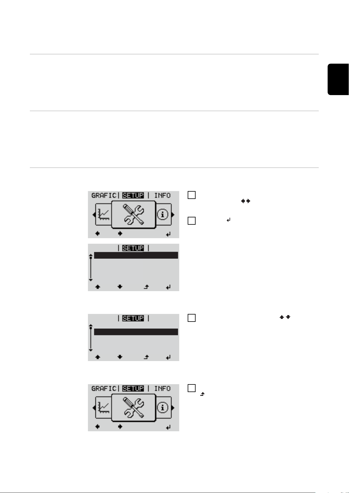
Voce di menu SETUP
Standby
Punto accesso WiFi
DATCOM
USB
Rele
Standby
Punto accesso WiFi
DATCOM
USB
Rele
Preimpostazione Completata la messa in funzione (ad esempio mediante l'installazione guidata),
l'inverter è preconfigurato in base al setup specifico del paese.
La voce di menu SETUP consente di modificare facilmente le preimpostazioni
dell'inverter per soddisfare le richieste e le esigenze specifiche dell'utente.
IT
Aggiornamenti
software
Navigazione
nella voce di
menu SETUP
IMPORTANTE! Il software potrebbe essere stato aggiornato, pertanto nell'appar-
ecchio in uso possono essere disponibili funzioni non descritte in queste istruzioni per l'uso o viceversa. Inoltre, le varie figure possono discostarsi dagli elementi di comando presenti sull'apparecchio in uso. Il funzionamento è tuttavia
identico.
Accesso alla voce di menu SETUP
Nel livello di menu, premere i tasti "Sinis-
1
tra" o "Destra" per selezionare la
voce di menu "SETUP".
2
Premere il tasto "Enter".
Viene visualizzata la prima voce della voce
di menu SETUP:
"Standby".
Scorrimento delle voci
3
Uscita da una voce
4
Viene visualizzato il livello di menu.
Se non si preme alcun tasto per 2 minuti
Utilizzare i tasti "Su" o "Giù" per
scorrere le voci disponibili.
Per uscire da una voce, premere il tasto
"Indietro".
89
Page 90

L'inverter passa dalla posizione in cui si trova all'interno del livello di menu
-
alla voce di menu "ATTUAL" (eccezione: voce del menu di setup "Standby").
L'illuminazione del display si spegne a meno che non sia stata attivata dur-
-
ante l'impostazione del display (vedere "Impostaz. display" - "Illuminazione").
Viene visualizzata la potenza correntemente alimentata o il codice State cor-
-
rentemente presente.
Impostazione
delle voci di
menu - In generale
Accedere al menu desiderato.
1
2
Selezionare la voce desiderata con i tasti "Su" o "Giù".
3
Premere il tasto "Enter".
Vengono visualizzate le impostazioni disponibili:
Selezionare l'impostazione desid-
4
erata con i tasti "Su" o "Giù".
Premere il tasto "Enter" per sal-
5
vare e applicare la selezione.
Premere il tasto "Esc" se non si
desidera salvare la selezione.
La prima posizione del valore da im-
postare lampeggia:
Selezionare un numero per la
4
prima posizione con i tasti "Su" o
"Giù".
5
Premere il tasto "Enter".
La seconda posizione del valore
lampeggia.
Ripetere le operazioni 4 e 5 fino a
6
che...
l'intero valore da impostare lampeggia.
7
Premere il tasto "Enter".
Ripetere eventualmente le op-
8
erazioni da 4 a 6 per impostare le
unità o altri valori fino a che
l'unità o il valore da impostare
lampeggia.
Premere il tasto "Enter" per sal-
9
vare e applicare le modifiche.
Esempio di applicazione: impostazione
dell'ora
90
Viene visualizzata la voce correntemente selezionata.
Premere il tasto "Esc" se non si
desidera salvare le modifiche.
Viene visualizzata la voce corrente-
mente selezionata.
Selezionare la voce del menu di setup
1
"Ora / Data".
2
Premere il tasto "Enter".
Page 91
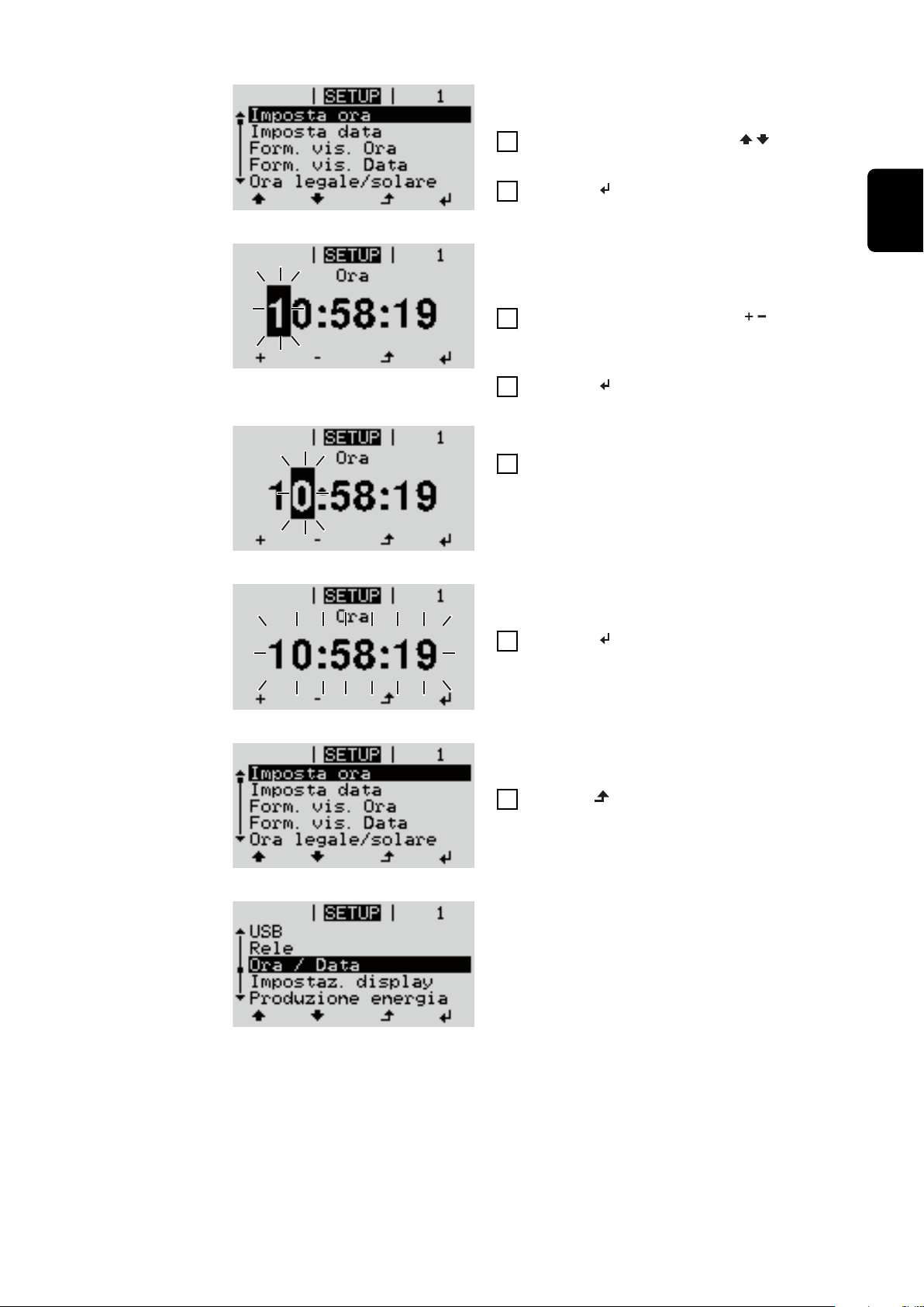
Viene visualizzata la panoramica dei valori
impostabili.
3
Utilizzare i tasti "Su" o "Giù" per
selezionare "Impostazione dell'ora"
4
Premere il tasto "Enter".
Viene visualizzata l'ora. (HH:MM:SS, formato 24 ore), la posizione delle decine per
l'ora lampeggia.
5
Utilizzare i tasti "Su" o "Giù" per
selezionare un valore per la cifra delle
decine per l'ora
6
Premere il tasto "Enter".
La posizione delle unità per l'ora lampeggia.
Ripetere le operazioni 5 e 6 per le unità
7
dell'ora, per i minuti e i secondi fino a
quando...
IT
l'ora impostata lampeggia.
8
Premere il tasto "Enter".
L'ora viene applicata e viene visualizzata la
panoramica dei valori impostabili.
4
Premere il tasto "Esc".
Viene visualizzata la voce del menu di setup
"Ora / Data".
91
Page 92

Voci del menu di setup
Standby Attivazione/disattivazione manuale del funzionamento in standby
Non si ha alimentazione di rete.
-
Il LED di avvio si accende con luce arancione.
-
Sul display vengono visualizzati alternativamente "STANDBY/ENTER".
-
Nel funzionamento in standby non è possibile richiamare o impostare altre
-
voci di menu all'interno del livello di menu.
Il passaggio automatico alla voce di menu "ATTUAL" se non si preme alcun
-
tasto per 2 minuti è disattivato.
Il funzionamento in standby può essere terminato solo manualmente, pre-
-
mendo il tasto "Enter".
È possibile riprendere in qualsiasi momento il funzionamento con ali-
-
mentazione di rete premendo il tasto "Enter", purché non siano presenti errori (codici State).
Impostazione del funzionamento in standby (interruzione manuale del funzionamento con alimentazione di rete):
Selezionare la voce "Standby".
1
2
Premere il tasto funzione "Enter".
Sul display vengono visualizzati alternativamente "STANDBY" e "ENTER".
La modalità Standby è ora attivata.
Il LED di avvio si accende con luce arancione.
Ripresa del funzionamento con alimentazione di rete:
In modalità standby, il display mostra "STANDBY" ed "ENTER" in alternanza.
1
Premere il tasto funzione "Enter" per riprendere il funzionamento con alimentazione di rete.
Viene visualizzata la voce "Standby".
Contemporaneamente l'inverter esegue la fase di avvio.
Una volta ripreso il funzionamento con alimentazione di rete, il LED dello stato di
funzionamento si accende con luce verde.
DATCOM Controllo di una comunicazione dati, immissione del codice inverter, impostazioni
protocollo
Gamma di
regolazione
Stato
Indica una comunicazione dati disponibile tramite Fronius Solar Net o un
errore verificatosi nella comunicazione dati.
Stato/Codice inverter/Tipo di protocollo
92
Codice inverter
Impostazione del codice (= indirizzo) dell'inverter in un impianto con più inverter.
Gamma di
regolazione
00-99 (00 = indirizzo dell'inverter "100")
Page 93

Impostazione di
01
fabbrica
IMPORTANTE! Nell'integrare più inverter in un sistema di comunicazione dati,
assegnare a ogni inverter un indirizzo univoco.
Tipo di protocollo
Specifica il protocollo di comunicazione per la trasmissione dei dati.
IT
Gamma di
Fronius Solar Net/Interface *
regolazione
Impostazione di
Fronius Solar Net
fabbrica
* Il tipo di protocollo Interface Protocol funziona solo senza scheda Fronius
Datamanager. Occorre rimuovere le schede Fronius Datamanager presenti
dall'inverter.
USB Per aggiornare il firmware o salvare i valori dettagliati dell'inverter sulla chiavetta
USB.
Gamma di
regolazione
Rim.sicura hardware/Aggiornam. software/Intervallo registr.
Rim.sicura hardware
Per scollegare una chiavetta USB dalla porta USB A dell'elemento da innesto per
la comunicazione dati senza perdere i dati.
È possibile rimuovere la chiavetta USB:
quando viene visualizzato il messaggio "OK"
-
quando il LED "Trasmissione dei dati" non lampeggia più o è spento.
-
Aggiornam. software
Per aggiornare il firmware dell'inverter utilizzando una chiavetta USB.
Procedura:
Scaricare il file di aggiornamento firmware "froxxxxx.upd"
1
(ad es. dal sito http://www.fronius.com; xxxxx sta per il rispettivo numero di
versione).
AVVERTENZA!
Per aggiornare il software dell'inverter senza problemi, è necessario che l'apposita chiavetta USB non presenti partizioni nascoste né crittografie (vedere
capitolo "Chiavette USB adatte").
Salvare il file di aggiornamento firmware sul livello dati esterno della
2
chiavetta USB.
Aprire il coperchio della scatola di comunicazione dati sull'inverter.
3
Collegare la chiavetta USB contenente il file di aggiornamento firmware alla
4
porta USB della scatola di comunicazione dati dell'inverter.
Nel menu di setup, selezionare la voce "USB" e poi "Aggiornam. software".
5
Premere il tasto "Enter".
6
93
Page 94

Attendere la visualizzazione sul display del confronto tra la versione firmware
7
correntemente presente sull'inverter e quella nuova:
1ª pagina: software Recerbo (LCD), software controller tastiera (KEY),
-
versione setup specifico per il paese (Set).
2ª pagina: software fonte d'energia (PS1, PS2).
-
Premere il tasto funzione "Enter" dopo ogni pagina.
8
L'inverter inizia a copiare i dati.
Vengono visualizzati "BOOT" e lo stato di avanzamento della memorizzazione dei
vari test in percentuale, fino alla copia dei dati di tutti i gruppi di componenti
elettronici.
Terminata la copia, l'inverter aggiorna una dopo l'altro i gruppi di componenti
elettronici necessari.
Vengono visualizzati "BOOT", il gruppo di componenti interessato e lo stato di
avanzamento dell'aggiornamento in percentuale.
In ultimo, l'inverter aggiorna il display.
Il display resta spento per circa 1 minuto, i LED di controllo e di stato lampeggiano.
Completato l'aggiornamento firmware, l'inverter passa alla fase di avvio e successivamente al funzionamento con alimentazione di rete. Scollegare la chiavetta
USB con la funzione "Rim.sicura hardware".
Durante l'aggiornamento del firmware dell'inverter le varie impostazioni configurate nel menu di setup restano memorizzate.
Intervallo registr.
Per attivare/disattivare la funzione di registrazione USB e per preimpostare un
intervallo di registrazione.
Unità Minuti
Gamma di
30 Min/20 Min/15 Min/10 Min/5 Min/No Log
regolazione
Impostazione di
30 Min
fabbrica
30 Min L'intervallo di registrazione è di 30 minuti; i nuovi dati di
registro vengono salvati sulla chiavetta USB ogni 30
minuti.
20 Min
15 Min
10 Min
5 Min L'intervallo di registrazione è di 5 minuti; i nuovi dati di
registro vengono salvati sulla chiavetta USB ogni 5
minuti.
94
No Log I dati non vengono salvati.
IMPORTANTE! Per garantire l'esecuzione corretta della funzione di registrazione
USB, occorre impostare correttamente l'ora. Per informazioni sull'impostazione
dell'ora, vedere "Voci del menu di setup", "Ora / Data".
Page 95

Rele (contatto di
commutazione a
potenziale zero)
Il contatto di commutazione a potenziale zero (relè) sull'inverter consente di
visualizzare i messaggi di stato (codici State), lo stato dell'inverter (ad es. funzionamento con alimentazione di rete) oppure le funzioni di gestione energetica.
Gamma di
regolazione
* Vengono visualizzati solo se la funzione "E-Manager" in "Modalita rele" è attivata.
Modalita rele
Modalita rele consente di illustrare le funzioni seguenti:
Funzione di allarme (Permanent (Permanente)/ALL (Tutto)/GAF)
-
Uscita attiva (ON (attiva)/OFF (disattiva))
-
Gestione energetica (E-Manager)
-
Gamma di
regolazione
Impostazione di
fabbrica
Funzione di allarme:
ALL
(Tutto)/
Permanent
(Permanente):
Modalita rele/Test rele/Punto inserzione*/Punto disin-
serzione*
ALL (Tutto)/Permanent (Permanente)/GAF/OFF (disat-
tiva)/ON (attiva)/E-Manager (Gestione energetica)
ALL (Tutto)
Attivazione del contatto di commutazione a potenziale zero in
caso di codici di servizio permanenti e temporanei (ad es.
breve interruzione del funzionamento con alimentazione di
rete, un codice di servizio visualizzato un determinato numero
di volte al giorno; impostabile nel menu "BASE").
IT
GAF Il relè viene attivato non appena si seleziona la modalità GAF.
Il relè viene aperto non appena la fonte d'energia segnala un
errore e passa dal normale funzionamento con alimentazione
di rete a uno stato di errore. Il relè può quindi essere utilizzato
per funzioni "fail-safe".
Esempio di applicazione
Se si utilizzano inverter monofase su una posizione multifase,
può rendersi necessario un rifasamento. Se su uno o più inverter si verifica un errore con conseguente scollegamento
dalla rete, occorre scollegare anche gli altri inverter per
mantenere l'equilibrio delle fasi. La funzione relè "GAF" è
utilizzabile in combinazione con Fronius Datamanager o un
dispositivo di protezione esterno per rilevare o segnalare la
mancata alimentazione o lo scollegamento dalla rete di un inverter e per scollegare dalla rete anche gli altri inverter mediante comando remoto.
Uscita attiva:
ON (attivo): Il contatto di commutazione a potenziale zero NO è costante-
mente attivo fino a quando l'inverter è in funzione (fino a
quando il display è illuminato o consente di visualizzare indicazioni).
OFF (disattivo):
Il contatto di commutazione a potenziale zero NO è disattivato.
Gestione energetica:
95
Page 96

E-Manager
(Gestione
energetica):
Test rele
Prova di funzionamento per verificare se il contatto di commutazione a potenziale zero si attiva.
Punto inserzione (solo con la funzione "Gestione energetica" attiva)
Per impostare il limite della potenza attiva a partire dal quale il contatto di
commutazione a potenziale zero viene attivato.
Ulteriori informazioni sulla funzione "Gestione energetica"
secondo il seguente paragrafo "Gestione energetica".
Gestione energetica
(alla voce di
menu "Relè")
Impostazione di
fabbrica
Gamma di
regolazione
Punto disinserzione (solo con la funzione "Gestione energetica" attiva)
Per impostare il limite della potenza attiva a partire dal quale il contatto di
commutazione a potenziale zero viene disattivato.
Impostazione di
fabbrica
Gamma di
regolazione
Utilizzando la funzione "Gestione energetica (E-Manager)" è possibile azionare il
contatto di commutazione a potenziale zero in modo che funga da attuatore.
Così facendo è possibile azionare un dispositivo di consumo collegato al contatto
di commutazione a potenziale zero preimpostando un punto di inserzione o disinserzione in funzione della potenza alimentata (potenza attiva).
Il contatto di commutazione a potenziale zero viene disattivato automaticamente
quando l'inverter non alimenta corrente nella rete pubblica
-
quando l'inverter viene messo manualmente in modalità di standby
-
in presenza di un valore preimpostato della potenza attiva < 10% della po-
-
tenza nominale dell'inverter
1000 W
Dal punto di disinserzione impostato fino alla potenza
nominale massima dell'inverter (W o kW)
500
Da 0 al punto d'inserzione impostato dell'inverter (W o
kW)
96
Per attivare la funzione "Gestione energetica", selezionare la voce "E-Manager" e
premere il tasto "Enter".
Con la funzione "Gestione energetica" attivata, in alto a sinistra sul display viene
visualizzata l'icona "Gestione energetica":
con il contatto di commutazione a potenziale zero NO disattivato (contatto
aperto)
con il contatto di commutazione a potenziale zero NC attivato (contatto chi-
uso).
Per disattivare la funzione "Gestione energetica", selezionare un'altra funzione
(ALL (Tutto)/Permanent (Permanente)/OFF (disattiva)/ON (attiva)) e premere il
tasto "Enter".
Page 97

AVVERTENZA!
Avvertenze per l'elaborazione del punto di inserzione e disinserzione
Una differenza eccessivamente ridotta tra il punto di inserzione e quello di disinserzione, nonché eventuali oscillazioni della potenza attiva, possono determinare molteplici cicli di commutazione.
Onde evitare accensioni e spegnimenti frequenti, la differenza tra il punto di inserzione e quello di disinserzione deve essere di almeno 100-200 W.
Quando si seleziona il punto di disinserzione, tenere conto dell'assorbimento di
potenza del dispositivo di consumo collegato.
Quando si seleziona il punto di inserzione, tenere conto delle condizioni meteo e
dell'irraggiamento solare previsto.
Esempio di applicazione
Punto di inserzione = 2000 W, punto di disinserzione = 1800 W
Se l'inverter eroga almeno 2000 W, il contatto di commutazione a potenziale zero
viene attivato.
Se la potenza dell'inverter scende al di sotto di 1800 W, il contatto di commutazione a potenziale zero viene disattivato.
Ciò consente di realizzare interessanti possibilità applicative, come l'azionamento
di una pompa di calore o di un climatizzatore utilizzando quanta più energia
elettrica autoprodotta possibile.
Ora / Data Impostazione dell'ora, della data, del formato di visualizzazione e del passaggio
automatico all'ora legale/solare.
IT
Gamma di
regolazione
Imposta ora
Impostazione dell'ora (hh:mm:ss o hh:mm am/pm - a seconda dell'impostazione in "Form. vis. Ora").
Imposta data
Impostazione della data (gg/mm/aaaa o mm/gg/aaaa - a seconda dell'impostazione in "Form. vis. Data").
Form. vis. Ora
Per preimpostare il formato di visualizzazione dell'ora.
Gamma di
regolazione
Impostazione di
fabbrica
Form. vis. Data
Per preimpostare il formato di visualizzazione della data.
Gamma di
regolazione
Imposta ora/Imposta data/Form. vis. Ora/Form. vis.
Data/Ora legale/solare
12hrs/24hrs
A seconda del setup specifico del paese.
mm/gg/aaaa o gg.mm.aa
97
Page 98

Impostazione di
fabbrica
Ora legale/solare
Per attivare/disattivare il passaggio automatico all'ora legale/solare.
IMPORTANTE! Utilizzare la funzione per il passaggio automatico all'ora legale/
solare solo se all'interno di un anello della Fronius Solar Net non sono presenti
componenti del sistema con funzionalità LAN o WLAN (ad es. Fronius Datalogger Web, Fronius Datamanager o Fronius Hybridmanager).
A seconda del setup specifico del paese.
Impostaz. display
Gamma di
regolazione
Impostazione di
fabbrica
IMPORTANTE! La corretta impostazione della data e dell'ora è indispensabile
per una giusta visualizzazione dei valori giornalieri e annuali e della curva caratteristica giornaliera.
Gamma di
regolazione
Lingua
Impostazione della lingua del display.
Gamma di
regolazione
Modalita notturna
La modalità notturna comanda il funzionamento di Fronius DATCOM e del display dell'inverter durante la notte o in caso di tensione CC insufficiente.
on (attiva)/off (disattiva)
on (attiva)
Lingua/Modalita notturna/Contrasto/Illuminazione
Inglese, tedesco, francese, spagnolo, italiano, olandese,
ceco, slovacco, ungherese, polacco, turco, portoghese,
romeno
Gamma di
regolazione
Impostazione di
fabbrica
AUTO: Il funzionamento di Fronius DATCOM è attivo fin quando un Froni-
us Datamanager è collegato a una Fronius Solar Net attiva e non interrotta.
Durante la notte il display dell'inverter è spento e può essere attivato premendo un tasto funzione qualsiasi.
ON
(attiva):
Il funzionamento di Fronius DATCOM è sempre attivo. L'inverter
mette ininterrottamente a disposizione la tensione di 12 V CC per
alimentare la Fronius Solar Net. Il display è sempre attivo.
IMPORTANTE! Se si imposta la modalità notturna di Fronius DATCOM su "ON (attiva)" o su "AUTO" con componenti della Fronius
Solar Net collegati, il consumo energetico notturno dell'inverter
aumenta a circa 7 W.
AUTO/ON (attiva)/OFF (disattiva)
OFF (disattiva)
98
Page 99

OFF
(disattiva):
Contrasto
Regolazione del contrasto sul display dell'inverter.
Funzionamento notturno di Fronius DATCOM assente, l'inverter
non necessita quindi di alcuna potenza di rete per alimentare la
della Fronius Solar Net.
Durante la notte il display dell'inverter è disattivato e Fronius
Datamanager non è disponibile. Per attivare comunque Fronius
Datamanager, disattivare e riattivare il lato CA dell'inverter e
premere un tasto funzione qualsiasi sul display dell'inverter entro
90 secondi.
IT
Gamma di
regolazione
Impostazione di
fabbrica
Dato che il contrasto dipende dalla temperatura, condizioni ambientali variabili
possono richiedere l'impostazione della voce di menu "Contrasto".
Illuminazione
Preimpostazione dell'illuminazione del display dell'inverter.
La voce di menu "Illuminazione" riguarda solo la retroilluminazione del display
dell'inverter.
Gamma di
regolazione
Impostazione di
fabbrica
AUTO: L'illuminazione del display dell'inverter viene attivata premendo un
tasto qualsiasi. Se per 2 minuti non si preme alcun tasto, l'illuminazione del display si spegne.
ON
(attiva):
L'illuminazione del display dell'inverter è sempre accesa se l'inverter è attivo.
0-10
5
AUTO/ON (attiva)/OFF (disattiva)
AUTO
Produzione energia
OFF
(disattiva):
Consente di modificare/configurare le seguenti impostazioni:
Variaz. contatore/Calibratura
-
Valuta
-
Tariffa ener. alim.
-
Fattore CO2
-
Gamma di
regolazione
Variaz. contatore/Calibratura
Calibratura del contatore.
L'illuminazione del display dell'inverter è sempre spenta.
Valuta/Tariffa ener. alim.
99
Page 100

Valuta
Impostazione della valuta.
Gamma di
regolazione
Tariffa ener. alim.
Impostazione del tasso di calcolo per il pagamento dell'energia alimentata.
Gamma di
regolazione
Impostazione di
fabbrica
Fattore CO2
Impostazione del fattore CO2 dell'energia alimentata.
Ventole Per verificare il funzionamento delle ventole.
Gamma di
regolazione
Selezionare la ventola desiderata con i tasti "Su" o "Giù".
-
Il test della ventola selezionata si avvia premendo il tasto "Enter".
-
La ventola continua a girare finché si preme il tasto "Esc" per uscire dal
-
menu.
3 cifre, A-Z
2 cifre, 3 cifre decimali
(A seconda del setup specifico del paese)
Test ventola n. 1/Test ventola n. 2 (a seconda dell'appar-
ecchio)
IMPORTANTE! Sul display dell'inverter non viene visualizzato se la ventola funziona correttamente. È possibile controllare il funzionamento della ventola solo
ascoltando e sentendo.
100
 Loading...