

Installation
Instructions
Fronius Symo 3 - 8,2 kW
Installation Instructions
EN
42,0426,0172,EN 028-10082022


Contents
Installation location and position 4
Explanation of safety notices 4
Safety 4
Proper use/intended purpose 5
Choosing the location of the inverter 6
Installation position 7
General comments regarding inverter installation location 8
Attaching the Mounting Bracket 9
Safety 9
Selecting wall plugs and screws 9
Recommended screws 9
Opening the inverter 9
Fitting the mounting bracket to a wall 10
Installing the mounting bracket on a mast or beam 11
Fitting the mounting bracket to metal supports 11
Do not warp or deform the mounting bracket 12
Connecting the inverter to the public grid (AC side) 13
Safety 13
Monitoring the grid 13
Type of AC cable 13
Preparing the aluminium cables for connection 13
AC terminals 14
Cross section of the AC cable 14
Connecting the inverter to the public grid (AC) 15
Maximum fuse rating on alternating current side 15
Notes regarding inverters with single and multiple MPP trackers 17
Inverter with single MPP tracker 17
Inverter with multiple MPP trackers 17
Connecting solar module strings to the inverter 19
General comments regarding solar modules 19
DC terminals 19
Connecting aluminium cables 19
Solar module strings - checking the polarity and voltage 20
Connecting solar module strings to the inverter (DC) 20
Data communication 24
Routing data communication cables 24
Installing the Datamanager in the inverter 24
Attaching the inverter to the mounting bracket 27
Attaching the inverter to the mounting bracket 27
Starting for the first time 29
Starting the inverter for the first time 29
Notes regarding software updates 32
Notes regarding software updates 32
USB Stick as a Data Logger and for Updating Inverter Software 33
USB flash drive as a datalogger 33
Data on the USB flash drive 33
Data volume and storage capacity 34
Buffer memory 35
Suitable USB flash drives 35
USB stick for updating the inverter software 36
Removing the USB flash drive 36
Notes regarding maintenance 37
Maintenance 37
Cleaning 37
Australian Conduits 38
Tightly sealing the conduits 38
Seal conduits 38
Serial Number Sticker for Customer Use 39
Serial number sticker for customer use 39
EN
3
Installation location and position
Explanation of
safety notices
DANGER!
Indicates immediate danger.
If not avoided, death or serious injury will result.
▶
WARNING!
Indicates a potentially hazardous situation.
If not avoided, death or serious injury may result.
▶
CAUTION!
Indicates a situation where damage or injury could occur.
If not avoided, minor injury and/or damage to property may result.
▶
NOTE!
Indicates a risk of flawed results and possible damage to the equipment.
Safety
WARNING!
Danger due to incorrect operation and incorrectly performed work.
This can result in serious injury and damage to property.
Only qualified personnel are authorised to commission your inverter and only
▶
within the scope of the respective technical regulations.
Read the Installation and Operating Instructions before installing and com-
▶
missioning the equipment.
WARNING!
Danger due to work that has been carried out incorrectly.
This may result in serious injury and damage to property.
Surge protective devices must only ever be installed and connected by a
▶
qualified electrical installation engineer!
Follow the safety rules.
▶
Ensure that both the AC side and the DC side of the inverter are de-ener-
▶
gised before carrying out any installation and connection work.
4

Fire prevention
CAUTION!
Danger due to poor or unprofessional installation.
This may result in damage to inverters and other live photovoltaic system components.
Poor or unprofessional installation can cause overheating of cables and terminal
connections and result in arcs. These can cause heat damage, which in turn may
lead to fires.
Observe the following when connecting AC and DC cables:
Tighten all terminals to the torque specified in the operating instructions
▶
Tighten all grounding terminals (PE / GND), including free ones, to the torque
▶
specified in the operating instructions
Do not overload cables
▶
Check cables for damage and verify that they are laid correctly
▶
Take note of the safety instructions, Operating Instructions and any local
▶
connection regulations
Using fastening screws, always screw the inverter firmly to the mounting
▶
bracket to the torque specified in the Operating Instructions.
Ensure that the fastening screws are tight before starting the inverter!
▶
Observe the manufacturer's connection, installation and operating instructions
at all times. To reduce the hazard potential to a minimum, perform all installation
and connection work carefully according to the instructions and regulations.
Refer to the device Installation Instructions for the tightening torques to be used
at the relevant terminal connections.
EN
Proper use/
intended purpose
The inverter is intended exclusively to convert direct current from solar modules
into alternating current and to feed this into the public grid.
Utilisation not in accordance with the intended purpose comprises:
Any use above and beyond this purpose
-
Making any modifications to the inverter that have not been expressly ap-
-
proved by Fronius
the installation of components that are not distributed or expressly ap-
-
proved by Fronius.
Fronius shall not be liable for any damage resulting from such action.
No warranty claims will be entertained.
Proper use also includes:
Carefully reading and obeying all the instructions and all the safety and
-
danger notices in the Operating Instructions and Installation Instructions
Performing all stipulated maintenance work
-
Installation as specified in the Installation Instructions
-
When designing the photovoltaic system, ensure that all components are operated within their permitted operating ranges at all times.
Observe all the measures recommended by the solar module manufacturer to
ensure that the solar module retains its properties in the long term.
Obey the regulations of the power supply company regarding connection methods and energy fed into the grid.
5
Choosing the
NH
3
location of the
inverter
The inverter is suitable for indoor installation.
The inverter is suitable for outdoor installation.
Because of its IP 65 protection class, the inverter is resistant to
water jets from any direction and can also be used in damp environments.
In order to minimise the heating up of the inverter, do not expose it to direct insolation. Install the inverter in a protected
location, e.g. in the vicinity of the solar modules or beneath the
eaves.
U
at an altitude of:
DCmax
0 to 2000 m = 1000 V
2000 to 2500 m = 900 V
2500 to 3000 m = 815 V
3000 to 3400 m = 750 V
IMPORTANT! The inverter must not be installed or used at altitudes above 3400 m.
Do not install the inverter in:
Areas where ammonia, corrosive vapours, acids or salts are
-
present
(e.g. fertiliser stores, ventilation openings from cattle sheds,
chemical plants, tanneries, etc.)
During certain operating phases the inverter may produce a
slight noise. For this reason it should not be installed in an occupied living area.
Do not install the inverter in:
Places where there is an increased risk of damage from farm
-
animals (horses, cattle, sheep, pigs, etc.)
Stables or adjoining areas
-
Storage areas for hay, straw, chaff, animal feed, fertilisers,
-
etc.
All inverters are designed to be dust-tight. However, in areas
with a heavy build-up of dust, the thermal efficiency may still be
impaired by dust forming on the cooling surfaces. Regular cleaning is necessary in such situations. We therefore recommend not
installing the inverter in areas and environments with high dust
accumulation.
6
Installation position
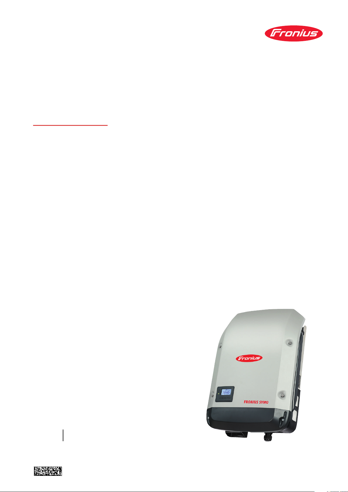
Do not install the inverter in:
Greenhouses
-
Storage or processing areas for fruit, vegetables or viticul-
-
ture products
Areas used in the preparation of grain, green fodder or an-
-
imal feeds
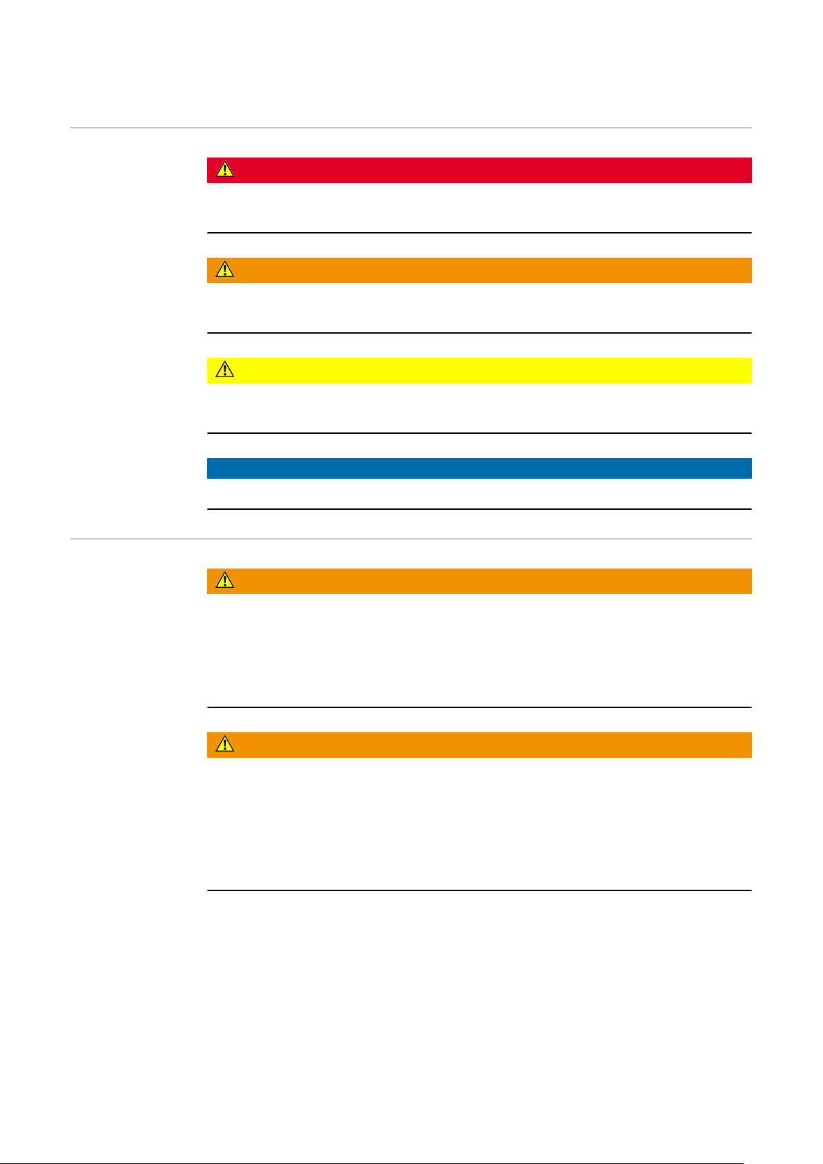
The inverter is suitable for vertical installation on a vertical wall or
column.
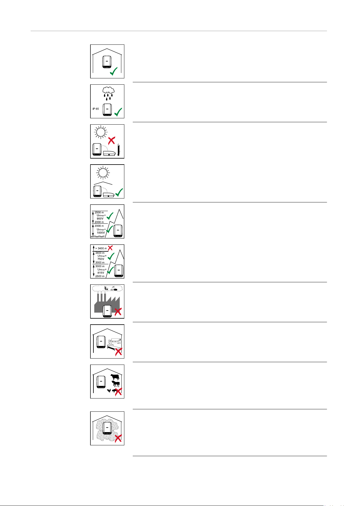
The inverter is suitable for a horizontal installation position.
EN
The inverter is suitable for installation on a sloping surface.
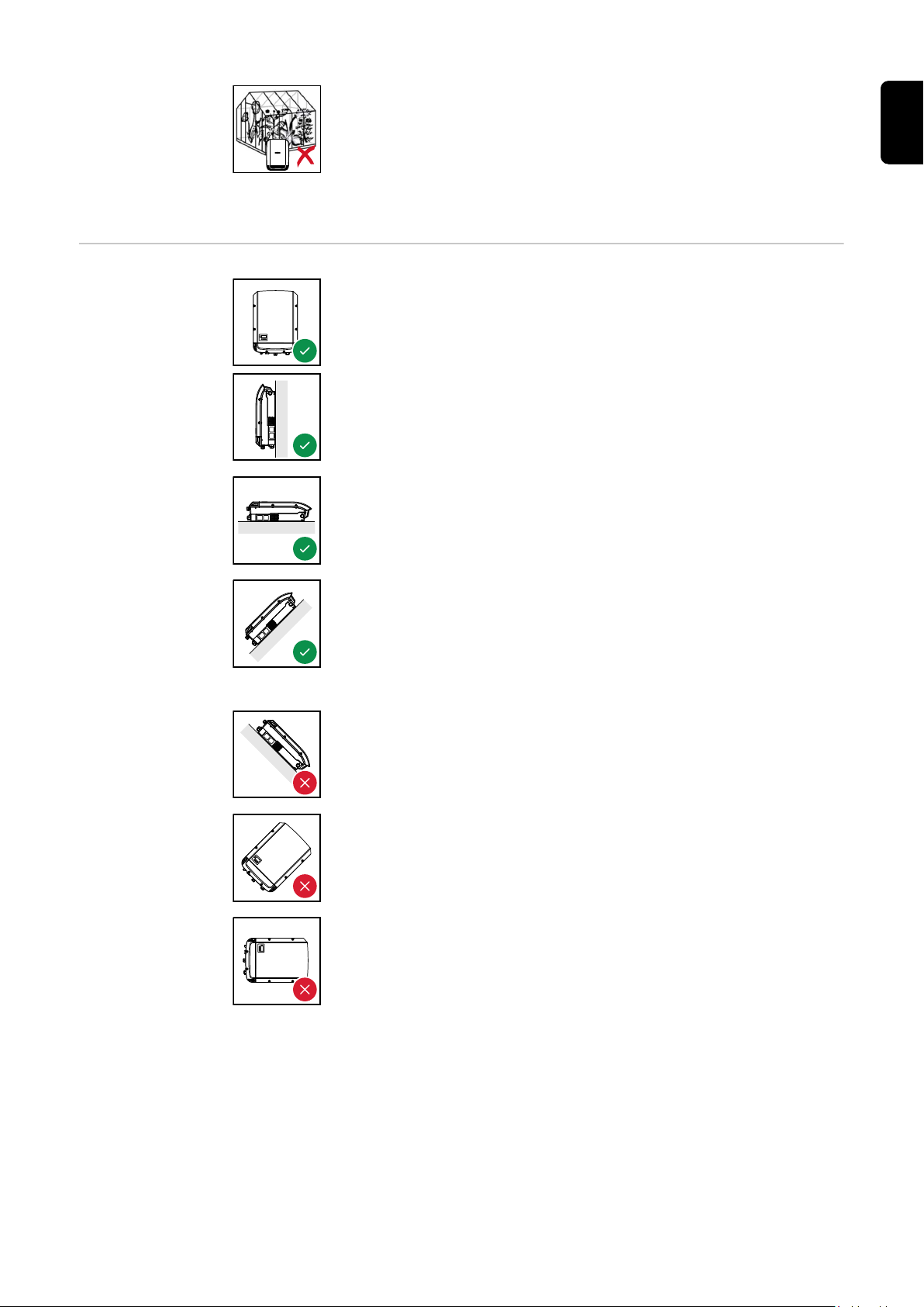
Do not install the inverter on a sloping surface with its connection
sockets at the top.
Do not install the inverter at an angle on a vertical wall or column.
Do not install the inverter horizontally on a vertical wall or pillar.
7

Do not install the inverter on a vertical wall or pillar with its connection sockets facing upwards.
Do not install the inverter overhanging with the connection sockets at the top.
Do not install the inverter overhanging with the connection sockets at the bottom.
Do not install the inverter on the ceiling.
General comments regarding
inverter installation location
Please note the following criteria when choosing a location for the inverter:
Install only on a solid, non-flammable surface
Max. ambient temperatures:
-25 °C / +60 °C
Relative humidity:
0-100%
The airflow within the inverter is
from the left to the top (cold air
taken in from the left, hot air dissipated out of the top).
The exhaust air can reach a temperature of 70 °C.
If the inverter is installed in a switch cabinet or a similar sealed area, then
forced-air ventilation must be provided to ensure adequate heat dissipation.
If the inverter is to be installed on the outer wall of a cattle shed, maintain a
minimum all-round clearance of 2 m between the inverter and all ventilation
and other openings in the building.
The installation location must not be exposed to ammonia, corrosive vapours,
salts or acids.
8

Attaching the Mounting Bracket
EN
Safety
WARNING!
Danger due to residual voltage in capacitors.
This may result in an electric shock.
Wait for the capacitors to discharge. The discharge time is five minutes.
▶
CAUTION!
Danger due to dirt or water on the terminals and contacts of the inverter's connection area.
This may result in damage to the inverter.
When drilling, ensure that terminals and contacts in the connection area do
▶
not become dirty or wet.
The mounting bracket without a power stage set does not conform to the
▶
protection class of the inverter as a whole, and therefore must not be installed without a power stage set.
The mounting bracket should be protected from dirt and moisture during in-
▶
stallation.
Note! Degree of protection IP 65 is only applicable if
the inverter is placed in the mounting bracket and permanently attached us-
-
ing screws,
the cover for the data communication area is permanently attached to the
-
inverter with screws.
Selecting wall
plugs and screws
Recommended
screws
Opening the inverter
Degree of protection IP 20 applies to the mounting bracket with no inverter and
the venting duct.
Important! Different fixings may be required to fit the mounting bracket depending on the type of underlying surface. Fixings are therefore not included in the
scope of supply of the inverter. The installer is responsible for selecting the right
type of fixing.
To install the inverter, the manufacturer recommends the use of steel or aluminium screws with a diameter of 6 - 8 mm.
WARNING!
Danger from inadequate ground conductor connection.
This can result in serious injury and damage to property.
The housing screws provide a suitable ground conductor connection for
▶
grounding the housing and must NOT be replaced by any other screws that
do not provide a reliable ground conductor connection.
9
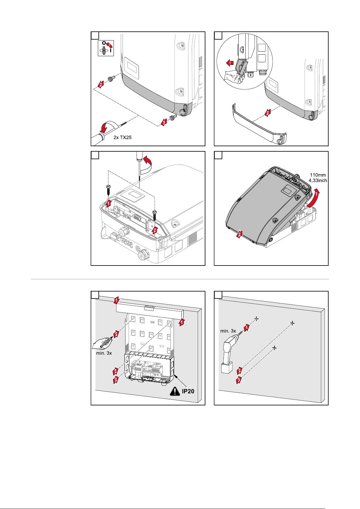
1 2
3 4
Fitting the
mounting bracket to a wall
1 2
Tip: Install the inverter so that its display is at
eye level
10
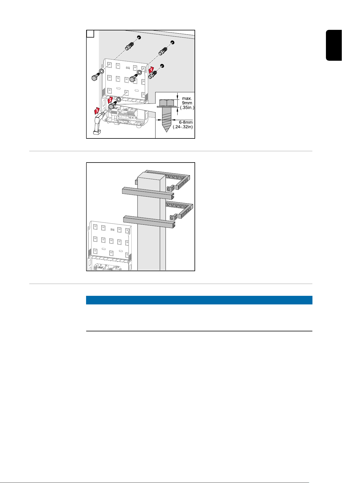
3
Note! When mounting the mounting
bracket on the wall, ensure that the
mounting bracket does not become
EN
warped or deformed.
Installing the
mounting bracket on a mast or
beam
Fitting the
mounting bracket to metal supports
When installing the inverter on a mast
or support, Fronius recommends the
"Pole Clamp" kit from Rittal GmbH (order no. SZ 2584.000).
This kit enables the inverter to be installed on round or rectangular masts
with the following diameters: Æ from
40 to 190 mm (round mast), ÿ from 50
to 150 mm (rectangular mast)
NOTE!
When mounted on metal supports, the inverter must not be exposed to rainwater or splashing water from the rear.
Provide suitable rainwater protection or splash water protection.
The mounting bracket must be securely screwed to at least four points.
11

1
Do not warp or
deform the
mounting bracket
Note! When fitting the mounting bracket to the wall, ensure that the mounting
bracket does not become warped or deformed.
12
 Loading...