

Page 1

/ Battery Charging Systems / Welding Technology / Solar Electronics
DE
EN-US
Fronius String Control 100/12 MET
Bedienungsanleitung
Anlagenüberwachung
Operating Instructions
System monitoring
42,0410,1940 001-05022013
Page 2

0
Page 3

Sehr geehrter Leser
Einleitung Wir danken Ihnen für Ihr entgegengebrachtes Vertrauen und gratulieren Ihnen zu Ihrem
technisch hochwertigen Fronius Produkt. Die vorliegende Anleitung hilft Ihnen, sich mit
diesem vertraut zu machen. Indem Sie die Anleitung sorgfältig lesen, lernen Sie die vielfältigen Möglichkeiten Ihres Fronius-Produktes kennen. Nur so können Sie seine Vorteile
bestmöglich nutzen.
Bitte beachten Sie auch die Sicherheitsvorschriften und sorgen Sie so für mehr Sicherheit
am Einsatzort des Produktes. Sorgfältiger Umgang mit Ihrem Produkt unterstützt dessen
langlebige Qualität und Zuverlässigkeit. Das sind wesentliche Voraussetzungen für hervorragende Ergebnisse.
DE
Erklärung Sicherheitshinweise
GEFAHR! Bezeichnet eine unmittelbar drohende Gefahr. Wenn sie nicht gemie-
den wird, sind Tod oder schwerste Verletzungen die Folge.
WARNUNG! Bezeichnet eine möglicherweise gefährliche Situation. Wenn sie
nicht gemieden wird, können Tod und schwerste Verletzungen die Folge sein.
VORSICHT! Bezeichnet eine möglicherweise schädliche Situation. Wenn sie
nicht gemieden wird, können leichte oder geringfügige Verletzungen sowie Sachschäden die Folge sein.
HINWEIS! Bezeichnet die Gefahr beeinträchtigter Arbeitsergebnisse und möglicher Schäden an der Ausrüstung.
WICHTIG! Bezeichnet Anwendungstipps und andere besonders nützliche Informationen.
Es ist kein Signalwort für eine schädliche oder gefährliche Situation.
Wenn Sie eines der im Kapitel „Sicherheitsvorschriften“ abgebildeten Symbole sehen, ist
erhöhte Achtsamkeit erforderlich.
1
Page 4

2
Page 5

Inhaltsverzeichnis
Sicherheitsvorschriften............................................................................................................................... 5
Allgemeines ............................................................................................................................................... 8
Gerätekonzept ...................................................................................................................................... 8
Funktionsprinzip.................................................................................................................................... 8
Wechselrichter ...................................................................................................................................... 8
Weitere Systemvoraussetzungen ......................................................................................................... 8
Bestimmungsgemäße Verwendung...................................................................................................... 8
Lieferumfang......................................................................................................................................... 9
Option ................................................................................................................................................... 9
Technische Daten................................................................................................................................. 9
Verwendete Abkürzungen und Bezeichnungen.................................................................................... 10
Warnhinweise am Gerät ....................................................................................................................... 10
Gerätebeschreibung .................................................................................................................................. 12
Sicherheit.............................................................................................................................................. 12
Gerätebeschreibung Gehäuse.............................................................................................................. 12
Gerätebeschreibung Geräteinneres...................................................................................................... 13
Metrische Verschraubungen an der Fronius String Control 100/12 montieren.......................................... 14
Allgemeines .......................................................................................................................................... 14
Empfehlung für die Reihenfolge zum Einsetzen der metrischen Verschraubungen............................. 14
Metrische Verschraubungen montieren ............................................................................................... 14
Anzugsmomente für metrische Verschraubungen................................................................................ 15
Fronius String Control 100/12 montieren ................................................................................................... 16
Auswahl von Dübel und Schrauben...................................................................................................... 16
Standortwahl ......................................................................................................................................... 16
Montagelage ......................................................................................................................................... 17
Fronius String Control 100/12 montieren .............................................................................................. 17
Solarmodul-Stränge an der Fronius String Control 100/12 anschließen ................................................... 19
Sicherheit.............................................................................................................................................. 19
Hinweise zum Anschließen der Solarmodul-Stränge an der Fronius String Control 100/12 ............... 19
Anschlussbelegung bei geerdeten Solarmodulen................................................................................. 20
Beispiel für Anschlussbelegung bei geerdeten Solarmodulen.............................................................. 20
Solarmodul-Stränge an der Fronius String Control 100/12 anschließen ............................................. 20
Abschließende Tätigkeiten ................................................................................................................... 21
Fronius String Control 100/12 mit dem Wechselrichter verbinden............................................................. 22
Sicherheit.............................................................................................................................................. 22
Vorbereitung ......................................................................................................................................... 22
Fronius String Control 100/12 mit dem Wechselrichter verbinden........................................................ 23
Kriterien zur richtigen Auswahl von Strangsicherungen ............................................................................ 24
Allgemeines .......................................................................................................................................... 24
Kriterien zur richtigen Auswahl von Strangsicherungen ....................................................................... 24
Auswirkungen von zu klein ausgelegten Sicherungen.......................................................................... 24
Empfehlung für die Sicherungen........................................................................................................... 24
Anwendungsbeispiel ............................................................................................................................. 25
Sicherungen.......................................................................................................................................... 25
Strangsicherungen einsetzen .................................................................................................................... 26
Sicherheit.......................................................................................................................
Strangsicherungen auswählen.............................................................................................................. 26
Strangsicherungen einsetzen ............................................................................................................... 26
Datenkommunikations-Kabel an der Fronius String Control 100/12 anschließen ..................................... 27
Anbindungsmöglichkeiten ..................................................................................................................... 27
Zusätzliche Isolation für Datenkommunikations-Kabel ......................................................................... 27
Konfigurationsbeispiel........................................................................................................................... 28
Sicherheit.............................................................................................................................................. 28
RJ 45 Datenkommunikations-Kabel an der Fronius String Control 100/12 anschließen ...................... 29
Mehradrige Datenkommunikations-Kabel an der Fronius String Control 100/12 anschließen ............. 30
Überstrom- und Unterspannungs-Abschaltung.......................................................................................... 32
Allgemeines .......................................................................................................................................... 32
Funktionsprinzip.................................................................................................................................... 32
Sicherheit.............................................................................................................................................. 32
Energieversorgung automatisch wiederherstellen ................................................................................ 32
....................... 26
DE
3
Page 6

Energieversorgung manuell wiederherstellen....................................................................................... 33
Externe Energieversorgung anschließen................................................................................................... 34
Allgemeines .......................................................................................................................................... 34
Sicherheit.............................................................................................................................................. 34
Externe Energieversorgung anschließen.............................................................................................. 34
Adresse einstellen...................................................................................................................................... 36
Sicherheit.............................................................................................................................................. 36
Allgemeines .......................................................................................................................................... 36
Adresse einstellen - Einstellbeispiele.................................................................................................... 36
Fronius String Control 100/12 schließen.................................................................................................... 37
Sicherheit.............................................................................................................................................. 37
Fronius String Control 100/12 schließen............................................................................................... 37
Einstellungen ............................................................................................................................................. 38
Allgemeines .......................................................................................................................................... 38
Erste Schritte ........................................................................................................................................ 38
Mögliche Einstellungen für die Fronius String Control 100/12 .............................................................. 38
Stränge pro Messkanal ......................................................................................................................... 38
Max. Ertragsabweichung ...................................................................................................................... 39
Schwellwert........................................................................................................................................... 39
Anzeige der Daten und Statusmeldungen ................................................................................................. 40
Anzeige der Daten ................................................................................................................................ 40
Statusmeldungen.................................................................................................................................. 40
Statusdiagnose und Fehlerbehebung ........................................................................................................ 41
Sicherheit.............................................................................................................................................. 41
Statusdiagnose und Fehlerbehebung................................................................................................... 41
Strangsicherungen tauschen, Wartung...................................................................................................... 42
Sicherheit.............................................................................................................................................. 42
Vorbereitung ......................................................................................................................................... 42
Strangsicherungen tauschen ................................................................................................................ 42
Abschließende Tätigkeiten.................................................................................................................... 43
Wartung ................................................................................................................................................ 43
4
Page 7

Sicherheitsvorschriften
DE
Allgemeines
Das Gerät ist nach dem Stand der Technik und den anerkannten sicherheitstechnischen Regeln gefertigt. Dennoch drohen bei Fehlbedienung oder Missbrauch Gefahr für
- Leib und Leben des Bedieners oder Dritte,
- das Gerät und andere Sachwerte des Betreibers,
- die effiziente Arbeit mit dem Gerät.
Alle Personen, die mit der Inbetriebnahme, Wartung und Instandhaltung des
Gerätes zu tun haben, müssen
- entsprechend qualifiziert sein,
- Kenntnisse im Umgang mit Elektroinstallationen haben und
- diese Bedienungsanleitung vollständig lesen und genau befolgen.
Die Bedienungsanleitung ist ständig am Einsatzort des Gerätes aufzubewah-
ren. Ergänzend zur Bedienungsanleitung sind die allgemein gültigen sowie
die örtlichen Regeln zu Unfallverhütung und Umweltschutz zu beachten.
Alle Sicherheits- und Gefahrenhinweise am Gerät
- in lesbarem Zustand halten
- nicht beschädigen
- nicht entfernen
- nicht abdecken, überkleben oder übermalen.
Die Positionen der Sicherheits- und Gefahrenhinweise am Gerät, entnehmen
Sie dem Kapitel „Allgemeines“ der Bedienungsanleitung Ihres Gerätes.
Störungen, die die Sicherheit beeinträchtigen können, vor dem Einschalten
des Gerätes beseitigen.
Es geht um Ihre Sicherheit!
Bestimmungsgemäße Verwendung
Umgebungsbedingungen
Das Gerät ist ausschließlich für den Einsatz im Sinne der bestimmungsgemäßen Verwendung zu benutzen.
Eine andere oder darüber hinaus gehende Benutzung gilt als nicht bestimmungsgemäß. Für hieraus entstandene Schäden haftet der Hersteller nicht.
Zur bestimmungsgemäßen Verwendung gehört auch
- das vollständige Lesen und Befolgen aller Hinweise, sowie aller Sicherheits- und Gefahrenhinweise aus der Bedienungsanleitung
- die Einhaltung aller Inspektions- und Wartungsarbeiten
- die Montage gemäß Bedienungsanleitung
Sofern zutreffend, auch folgende Richtlinien anwenden:
- Bestimmungen des Energieversorgungs- Unternehmens für die
Netzeinspeisung
- Hinweise der Solarmodul-Hersteller
Betrieb oder Lagerung des Gerätes außerhalb des angegebenen Bereiches
gilt als nicht bestimmungsgemäß. Für hieraus entstandene Schäden haftet
der Hersteller nicht.
Genaue Informationen über die zulässigen Umgebungsbedingungen entnehmen Sie den technischen Daten Ihrer Bedienungsanleitung.
5
Page 8

Qualifiziertes Personal
Die Serviceinformationen in dieser Bedienungsanleitung sind nur für qualifiziertes Fachpersonal bestimmt. Ein elektrischer Schlag kann tödlich sein.
Führen Sie keine anderen als die in der Dokumentation angeführten Tätigkeiten aus. Das gilt auch, wenn sie dafür qualifiziert sind.
Sämtliche Kabel und Leitungen müssen fest, unbeschädigt, isoliert und ausreichend dimensioniert sein. Lose Verbindungen, angeschmorte, beschädigte
oder unterdimensionierte Kabel und Leitungen sofort von einem autorisierten
Fachbetrieb instandsetzen lassen.
Wartung und Instandsetzung dürfen nur durch einen autorisierten Fachbetrieb
erfolgen.
Bei fremdbezogenen Teilen ist nicht gewährleistet, dass sie beanspruchungsund sicherheitsgerecht konstruiert und gefertigt sind. Nur Original-Ersatzteile
verwenden (gilt auch für Normteile).
Ohne Genehmigung des Herstellers keine Veränderungen, Ein- oder Umbauten am Gerät vornehmen.
Bauteile in nicht einwandfreiem Zustand sofort austauschen.
Sicherheitsmaßnahmen am Einsatzort
EMV Geräte-Klassifizierungen
EMV-Maßnahmen
Bei der Installation von Geräten mit Kühlluft-Öffnungen sicherstellen, dass die Kühlluft ungehindert durch die Luftschlitze ein- und austreten kann. Das Gerät nur gemäß der am
Leistungsschild angegebenen Schutzart betreiben.
Geräte der Emissionsklasse A:
- sind nur für den Gebrauch in Industriegebieten vorgesehen
- können in anderen Gebieten leitungsgebundene und gestrahlte
Störungen verursachen.
Geräte der Emissionsklasse B:
- erfüllen die Emissionsanforderungen für Wohn- und Industriegebiete. Dies gilt auch für Wohngebiete, in denen die Energieversorgung aus dem öffentlichen Niederspannungsnetz erfolgt.
EMV Geräte-Klassifizierung gemäß Leistungsschild oder technischen Daten.
In besonderen Fällen können trotz Einhaltung der genormten EmissionsGrenzwerte Beeinflussungen für das vorgesehene Anwendungsgebiet auftreten (z.B. wenn empfindliche Geräte am Aufstellungsort sind oder wenn der
Aufstellungsort in der Nähe von Radio- oder Fernsehempfängern ist). In diesem Fall ist der Betreiber verpflichtet, angemessene Maßnahmen für die Störungsbehebung zu ergreifen.
Elektroinstallationen
6
Elektroinstallationen nur gemäß den entsprechenden nationalen sowie regionalen Normen und Bestimmungen durchführen.
Page 9

ESD-Schutzmaßnahmen
Gefahr einer Beschädigung elektronischer Komponenten durch elektrische
Entladung. Bei Austausch und Installation der Komponenten geeignete ESDSchutzmaßnahmen treffen.
DE
Sicherheitsmaßnahmen im Normalbetrieb
Sicherheitskennzeichnung
Entsorgung
Das Gerät nur betreiben, wenn alle Schutzeinrichtungen voll funktionstüchtig
sind. Sind die Schutzeinrichtungen nicht voll funktionsfähig, besteht die Gefahr für
- Leib und Leben des Bedieners oder Dritte,
- das Gerät und andere Sachwerte des Betreibers
- die effiziente Arbeit mit dem Gerät
Nicht voll funktionstüchtige Sicherheitseinrichtungen vor dem Einschalten des
Gerätes von einem autorisierten Fachbetrieb instandsetzen lassen.
Schutzeinrichtungen niemals umgehen oder außer Betrieb setzen.
Geräte mit CE-Kennzeichnung erfüllen die grundlegenden Anforderungen der
Niederspannungs- und Elektromagnetischen Verträglichkeits-Richtlinie. Nähere Informationen dazu finden Sie im Anhang oder im Kapitel „Technische
Daten“ Ihrer Dokumentation.
Werfen Sie dieses Gerät nicht in den Hausmüll! Gemäß Europäischer Richtlinie 2002/96/EG über Elektro- und Elektronik-Altgeräte und Umsetzung in nationales Recht, müssen verbrauchte Elektrowerkzeuge getrennt gesammelt
und einer umweltgerechten Wiederverwertung zugeführt werden. Stellen Sie
sicher, dass Sie Ihr gebrauchtes Gerät bei Ihrem Händler zurückgeben oder
holen Sie Informationen über ein lokales, autorisiertes Sammel- und Entsorgungssystem ein. Ein Ignorieren dieser EU-Direktive kann zu potentiellen
Auswirkungen auf die Umwelt und Ihre Gesundheit führen!
Datensicherheit
Urheberrecht
Für die Datensicherung von Änderungen gegenüber den Werkseinstellungen
ist der Anwender verantwortlich. Im Falle gelöschter persönlicher Einstellungen haftet der Hersteller nicht.
Das Urheberrecht an dieser Bedienungsanleitung verbleibt beim Hersteller.
Text und Abbildungen entsprechen dem technischen Stand bei Drucklegung.
Änderungen vorbehalten. Der Inhalt der Bedienungsanleitung begründet keinerlei Ansprüche seitens des Käufers. Für Verbesserungsvorschläge und Hinweise auf Fehler in der Bedienungsanleitung sind wir dankbar.
7
Page 10

Allgemeines
Gerätekonzept Die Fronius String Control 100/12 ist für den Einsatz in netzgekoppelten Photovoltaikanla-
gen mit mehreren Solarmodulsträngen konzipiert.
Bis max. 12 Solarmodul-Stränge können am Eingang der Fronius String Control 100/12
zusammengefasst werden, um diese am Ausgang auf je eine DC+ und DC- Hauptleitung
zu reduzieren.
Dabei überwacht die Fronius String Control 100/12 die eingehenden Solarmodul-Stränge,
um Fehler im Solarmodul-Feld erkennen zu können.
In Verbindung mit einer Fronius Anlagenüberwachung (z.B. Solar.web, ...) und einem
Fronius Datalogger können Statusmeldungen per E-Mail oder SMS versendet werden. Ein
defektes Solarmodul lässt sich somit rasch ausfindig machen.
Funktionsprinzip - Jeweils 6 der eingehenden Solarmodul-Stränge werden zu einem Messkanal zusam-
mengefasst.
- 2 Messkanäle erfassen über den ganzen Einspeisetag den Gesamtstrom der jeweils
angeschlossenen Solarmodul-Stränge.
- Am Abend bildet die Fronius String Control 100/12 den Mittelwert aller Messkanäle.
- Die Fronius String Control 100/12 vergleicht den Strom jedes Messkanals mit dem
Mittelwert aller Messkanäle.
- Registriert die Fronius String Control 100/12 eine Abweichung eines Messkanals von
diesem Mittelwert, wird eine Statusmeldung an den Fronius Datalogger ausgegeben.
- Die zulässige Abweichung vom Mittelwert ist frei definierbar.
Wechselrichter Die Fronius String Control 100/12 ist ausschließlich für den Betrieb mit folgenden Wech-
selrichtern geeignet:
- Fronius IG 300 / 390 / 400 / 500
- Fronius IG Plus / Fronius IG Plus V
- Fronius CL
Weitere Systemvoraussetzungen
Bestimmungsgemäße Verwendung
- Fronius Datalogger
- Fronius Anlagenüberwachung
- PC mit installierter Software Fronius Solar.access
- oder PC mit Internet-Anbindung und Zugang zu Fronius Solar.web
Das Gerät ist ausschließlich als Sammler und Messeinrichtung für die DC-Stränge von den
Solarmodulen geeignet. Der Betrieb des Geräts ist nur in Verbindung mit einem Wechselrichter zulässig, welcher den gesetzlichen Bestimmungen des Aufstellungsortes entspricht.
Eine andere oder darüber hinausgehende Benutzung gilt als nicht bestimmungsgemäß.
Für hieraus entstehende Schäden haftet der Hersteller nicht.
Zur bestimmungsgemäßen Verwendung gehört auch das Beachten aller Hinweise aus der
Bedienungsanleitung.
8
Page 11

Lieferumfang - 1 Fronius String Control 100/12 (im Metallgehäuse)
- 2 metrische Verschraubungen M32 inkl. Gegenmuttern
- 24 metrische Verschraubungen M16 inkl. Gegenmuttern
- 10 Blindverschraubungen M16
- 1 metrische Verschraubung M20 inkl. Gegenmutter
- 1 metrische Blindverschraubung M20
- 1 metrische Verschraubung M25 inkl. Gegenmutter
- 1 Gummieinsatz M25
- 2 Kunststoff-Bolzen
- 1 Silikonschlauch Ø 25 x 510 mm (für Datenkommunikations-Kabel)
- 1 Silikonschlauch Ø 14 x 420 mm (für externe Stromversorgung)
- 1 Dichtungs-Set (24 O-Ringe M16, 2 O-Ringe M32, 2 O-Ringe M20/M25)
- 1 DC Connector Kit (2 Anschlussverteiler inklusive Montagezubehör)
- 1 Beiblatt „Brandverhütung“
- 1 Beiblatt „Montagehinweis“
Option Falls ein Überspannungs-Schutz Typ 1 oder Typ 2 gewünscht ist, kann dieser in der Froni-
us String Control 100/12 auf der dafür vorgesehenen Hutschiene montiert werden.
DE
Technische Daten
max. Eingangsspannung im Leerlauf 600 V
max. Eingangsstrom 100 A
max. Eingangsstrom pro Sicherungshalter 20 A
max. Stranganzahl (mit integrierter Solarmodul-Sicherung) 12
max. Leitungs-Querschnitt für Klemmen an der Solarmodul-
Seite
max. Leitungs-Querschnitt für die M12-Anschlüsse an der
Wechselrichter-Seite
Anzahl Messkanäle 2
max. Strom pro Messkanal 50 A
Verschraubung zur Kabelfixierung an der Solarmodul-Seite M16
Verschraubung zur Kabelfixierung an der Wechselrichter-Seite M32
Schutzart IP 55
Umgebungsbedingungen -25 °C - +60 °C
Abmessungen (ohne Verschraubungen) 500 x 350 x 145 mm
19.7 x 13.8 x 5.7 in.
Versorgung DATCOM über Solar Net
optional über 12 V Netzteil
max. Stromverbrauch Solar Net 110 mA
Gewicht 6,2 kg
*) gilt für ein- und mehrdrähtige Kabel:
10 mm² bei einem maximalen Kabeldurchmesser von 7 mm
10 mm² *)
95 mm²
-13 °F - +140 °F
13.67 lbs.
9
Page 12

Verwendete Abkürzungen und
Bezeichnungen
DC-Kabel ‘OUT’ DC-Ausgangskabel von der Fronius String Control 100/12 zum
Wechselrichter;
Die Polarität der DC-Kabel ‘OUT’ hängt davon ab, wie die Solarmodul-Stränge an der Fronius String Control 100/12 angeschlossen werden.
DC-Kabel ‘IN’ Solarmodul-Stränge von den Solarmodulen zur Fronius String
Control 100/12;
ein Solarmodul-Strang besteht jeweils aus einem DC+ Kabel
und einem DC- Kabel.
Warnhinweise am
Gerät
An der Fronius String Control 100/12 befinden sich Warnhinweise und Sicherheitssymbole. Diese Warnhinweise und Sicherheitssymbole dürfen weder entfernt noch übermalt
werden. Die Hinweise und Symbole warnen vor Fehlbedienung, woraus schwerwiegende
Personen- und Sachschäden resultieren können.
Sicherheitssymbole:
10
Gefahr von schwerwiegenden Personen- und Sachschäden durch Fehlbedienung
Beschriebene Funktionen erst anwenden, wenn folgende Dokumente vollständig gelesen und verstanden wurden:
- diese Bedienungsanleitung
- sämtliche Bedienungsanleitungen der Systemkomponenten der Photovoltaikanlage, insbesondere Sicherheitsvorschriften
Gefährliche elektrische Spannung
Page 13

Text der Warnhinweise:
WARNUNG!
Ein elektrischer Schlag kann tödlich sein.
Gefahr durch DC-Spannung von den Solarmodulen.
Mehr als eine Versorgungsquelle.
Vor Wartungsarbeiten alle Versorgungsquellen trennen.
Vor dem Öffnen des Gerätes dafür sorgen, dass Eingangsseite und Ausgangsseite vor
dem Gerät spannungsfrei sind!
Gefährliche Spannung durch Solarmodule, die Licht ausgesetzt sind.
Der Anschlussbereich darf nur von lizenzierten Elektro-Installateuren geöffnet werden.
DE
11
Page 14

Gerätebeschreibung
(8)
(9) (9) (9)
(9)(9)(9)
Sicherheit
Gerätebeschreibung Gehäuse
WARNUNG! Fehlbedienung kann schwerwiegende Personen- und Sachschä-
den verursachen. Beschriebene Funktionen erst anwenden, wenn folgende Dokumente vollständig gelesen und verstanden wurden:
- diese Bedienungsanleitung
- sämtliche Bedienungsanleitungen der Systemkomponenten, insbesondere
Sicherheitsvorschriften
(1) (2) (3)
(4)(5)(6)(7)
Fronius String Control 100/12 - Vorderansicht Fronius String Control 100/12 - Schrägansicht von
oben
Pos. Bezeichnung
(1) Kabeleingang für metrische Verschraubungen M16
(für DC-Kabel ‘IN’)
Kabeldurchmesser 3 - 7 mm
(2) Kabeleingang für metrische Verschraubungen M16
(für DC-Kabel ‘IN’)
Kabeldurchmesser 3 - 7 mm
(3) Kabeleingang für metrische Verschraubung M25
(für Datenkommunikations-Kabel)
(4) Druckausgleichs-Membran
(5) Kabeleingang für metrische Verschraubung M32
(für DC-Kabel ‘OUT’)
Kabeldurchmesser 11 - 21 mm
(6) Kabeleingang für metrische Verschraubung M32
(für DC-Kabel ‘OUT’)
Kabeldurchmesser 11 - 21 mm
(7) Kabeleingang für metrische Verschraubung M20
(für Erdungskabel)
Kabeldurchmesser 8 - 13 mm
12
Nur bei optionaler Verwendung eines Überspannungsschutzes erforderlich.
(8) Deckel
(9) Deckelschraube
Page 15

Gerätebeschrei-
(1) (2) (3) (4) (5) (6) (8)(7)
(12) (9)(10)(11)
bung Geräteinneres
WICHTIG! Metrische Verschraubungen und Blindverschraubungen sind bei Auslieferung
nicht an der Fronius String Control 100/12 montiert, sondern werden nur beigelegt.
DE
Fronius String Control 100/12 - Geräteinneres
Pos. Bezeichnung
(1) Hutschiene
zur Montage eines handelsüblichen Überspannungsschutz
(2) Messkanal 1
(3) RJ 45 Anschlüsse für Datenkommunikations-Kabel
(4) Anschlussklemmen für Datenkommunikations-Kabel
Kabelquerschnitt max. 2,5 mm²
(5) Anschlussklemmen für Datenkommunikations-Kabel
Kabelquerschnitt max. 2,5 mm²
(6) Adress-Schalter
(7) Anschluss für externe Versorgung 12 V DC
(8) Messkanal 2
(9) Anschlussklemmen mit Sicherungshaltern für DC-Kabel ‘IN‘
Kabelquerschnitt 2,5 - 10 mm² *)
(10) Anschluss M12 für DC-Kabel ‘OUT’
(11) Anschluss M12 für DC-Kabel ‘OUT’
(12) Anschlussklemmen für DC-Kabel ‘IN’
Kabelquerschnitt 2,5 - 10 mm² *)
*) gilt für ein- und mehrdrähtige Kabel:
10 mm² bei einem maximalen Kabeldurchmesser von 7 mm
13
Page 16

Metrische Verschraubungen an der Fronius String
M16
M32 M32
M20 *
M16
12 13
14
M16
1
2
3
4
5
6
7
8
9
10
11 15
M25
M16
M16
M16
16
171819
20
21
22
23
24
25
26
27
28
2
4
Control 100/12 montieren
Allgemeines - Metrische Verschraubungen entsprechend der Anzahl der vorhandenen Solarmodul-
Stränge einsetzen, in leere Positionen Blindverschraubungen einsetzen.
- Reihenfolge beim Einsetzen der metrischen Verschraubungen beachten:
von unten nach oben und von links nach rechts.
- O-Ringe entsprechend ihrer Größe an den metrischen Verschraubungen anbringen.
- Metrische Verschraubungen und Blindverschraubungen entsprechend ihrer Größe
mit dem angegebenen Anzugsmoment anziehen.
Empfehlung für
die Reihenfolge
zum Einsetzen
der metrischen
Verschraubungen
Metrische Verschraubungen
montieren
* nur bei optionalem Überspannungsschutz als Auslass für das Erdungskabel
1
Fronius String Control 100/12 öffnen Metrische Verschraubungen montieren:
2
1 Gegenmutter
2 O-Ring
3 Verschraubung
4 Zugentlastung
14
Page 17

Anzugsmomente
für metrische Verschraubungen
Größe Gegenmutter / Verschraubung Verschraubung / Zugentlastung
M16 3,0 Nm 2,0 Nm
M20 6,0 Nm 4,0 Nm
M25 8,0 Nm 5,0 Nm
M32 10,0 Nm 6,5 Nm
Die Verschraubung erfolgt an der Innenseite der Fronius String Control 100/12.
Das Anzugsmoment für die Zugentlastung gilt bei angeschlossenen Kabeln.
DE
15
Page 18

Fronius String Control 100/12 montieren
Auswahl von Dübel und Schrauben
Standortwahl Beachten Sie bei der Auswahl des Standortes folgende Kriterien:
Je nach Untergrund sind unterschiedliche Dübel und Schrauben für die Montage der Fronius String Control 100/12 erforderlich. Dübel und Schrauben sind daher nicht im Lieferumfang der Fronius String Control 100/12 enthalten. Der Monteur ist für die richtige Auswahl
von passenden Dübeln und Schrauben selbst verantwortlich.
- Installation nur auf festem Untergrund
- Die Umgebungstemperatur darf -25 °C nicht unter- und +60 °C nicht überschreiten
- Die Fronius String Control 100/12 kann im geschützten Außenbereich montiert werden; unmittelbare Nässeeinwirkung vermeiden.
- Vor direkter Sonneneinstrahlung und Witterungseinflüssen schützen
- Wenn möglich unter den Solarmodulen montieren
HINWEIS! Um Verzug an der
Fronius String Control 100/12 zu
verhindern, das Gerät nur auf einer ebenen Fläche montieren!
16
Page 19

Montagelage
0-90°
Die Fronius String Control 100/12 kann zwischen vertikal und horizontal in jeder beliebigen Lage montiert werden.
Bei vertikaler und schräger Monatagelage müssen die Kabeleinund -ausgänge nach unten zeigen.
DE
Fronius String
Control 100/12
montieren
HINWEIS! Die Montage der Fronius String Control 100/12 darf ausschließlich an
den dafür vorgesehenen Montagelaschen erfolgen.
Keinesfalls Bohrungen im Gehäuse anbringen!
1
3
2
4
17
Page 20

5
18
Page 21

Solarmodul-Stränge an der Fronius String Control
1
2
3
4
56
7
89101112
1234
56 78
9101112
100/12 anschließen
Sicherheit
Hinweise zum Anschließen der Solarmodul-Stränge
an der Fronius String Control
100/12
WARNUNG! Ein elektrischer Schlag kann tödlich sein. Gefahr durch DC-Span-
nung von den Solarmodulen.
- Vor allen Anschlussarbeiten dafür sorgen, dass Eingangsseite und Ausgangsseite vor dem Gerät spannungsfrei sind!
- Sämtliche Anschlussarbeiten dürfen nur von lizenzierten Elektro-Installateuren durchgeführt werden!
- Beachten Sie die Sicherheitsvorschriften in dieser Bedienungsanleitung.
HINWEIS! An den Anschlussklemmen für DC-Kabel ‘IN’
und an den Anschlussklemmen mit Sicherungshaltern für
DC-Kabel ‘IN’ nur jeweils DC Kabel mit gleicher Polarität
anschließen.
HINWEIS! Um ein problemloses Anschließen der DC-Kabeln an den Anschlussklemmen zu gewährleisten, eine Mindestlänge der DC-Kabel von 330 mm berücksichtigen (gemessen von der inneren Unterkante der Fronius String Control
100/12).
DE
HINWEIS! Reihenfolge beim Einführen und Anschließen der DC-Kabel beach-
ten: von unten nach oben und von innen nach außen.
Empfehlung für die Reihenfolge zum Einführen und Anschließen der DC-Kabel
HINWEIS! Beim Anschluss von weniger als 12 Solarmodul-Strängen empfiehlt
es sich, die DC-Kabel möglichst gleichmäßig auf die Messkanäle aufzuteilen.
z.B.: 8 Solarmodul-Stränge so anschließen, dass pro Messkanal 4 DC-Kabel angeschlossen werden. Nach Möglichkeit einzelne Klemmen zwischen den DC-Kabeln frei lassen.
HINWEIS! Beim Anschluss von Solarmodulen mit unterschiedlicher Leistungstoleranz empfiehlt es sich, die Leistung möglichst gleichmäßig auf die Messkanäle
aufzuteilen.
19
Page 22

Anschlussbele-
(B)(A)
(
B‘)(A‘)
+
-
1
(A)
(C)
gung bei geerdeten Solarmodulen
Bei geerdeten Solarmodulen dürfen an den abgesicherten Klemmen (A) nur die ungeerdeten Pole der Solarmodul-Stränge angeschlossen werden.
Beispiel für Anschlussbelegung
bei geerdeten Solarmodulen
Negative Solarmodul-Erdung
Positive Solarmodul-Erdung
-
(B)(A)
B‘)(A‘)
(
+
DC- DC+
B (in) B‘ (out) A‘ (out) A (in)
DC+ DC-
B (in) B‘ (out) A‘ (out) A (in)
SolarmodulStränge an der
Fronius String
Control 100/12
anschließen
Belegung bei Solarmodul-Erdung am Minuspol Belegung bei Solarmodul-Erdung am Pluspol
2
(B)
(A)
(A) Anzugsmoment 2,0 Nm
(B) Anzugsmoment 1,5 Nm
20
(C) Anzugsmoment 2,0 Nm
Page 23

Abschließende
Tätigkeiten
HINWEIS!
- Mit den DC-Kabeln der Solarmodule außerhalb der Geräte eine Schleife bilden!
- Geeignete Zugentlastung vorsehen, dass nicht das volle Kabelgewicht auf
die Gerätewand einwirkt.
DC IN
Schlaufenbildung bei vertikaler Montagelage
DE
DC IN
Schlaufenbildung bei horizontaler Montagelage
21
Page 24

Fronius String Control 100/12 mit dem Wechselrich-
1
3
(B)
(A)
5
6
ter verbinden
Sicherheit
Vorbereitung
WARNUNG! Ein elektrischer Schlag kann tödlich sein. Gefahr durch DC-Span-
nung von den Solarmodulen.
- Vor allen Anschlussarbeiten dafür sorgen, dass Eingangsseite und Ausgangsseite vor dem Gerät spannungsfrei sind!
- Sämtliche Anschlussarbeiten dürfen nur von lizenzierten Elektro-Installateuren durchgeführt werden!
- Beachten Sie die Sicherheitsvorschriften in dieser Bedienungsanleitung.
2
2
M12
1
M12
3
4
M12
DC-Kabel ‘OUT‘
3
(A) Anzugsmoment 28 Nm
(B) Anzugsmoment 6 Nm
HINWEIS! DC-Kabel ‘OUT’ entsprechend ihrer vorgesehenen Polarität kennzeichnen.
22
Page 25

Fronius String
Control 100/12
mit dem Wechselrichter verbinden
DC-Kabel ‘OUT’ gemäß Bedienungsanleitung des Wechselrichters am Wechselrich-
1
ter anschließen
HINWEIS! Beim Anschließen folgende Punkte beachten:
- Ist eine Solarmodul-Erdung erforderlich oder vorhanden?
Falls ja, Besonderheiten der jeweiligen Solarmodul-Erdung berücksichtigen
- Bei vorhandener Solarmodul-Erdung empfiehlt Fronius, Strangsicherungen
immer im nichtgeerdeten Zweig einzusetzen.
- DC-Kabel ‘OUT’ polrichtig am Wechselrichter anschließen
DE
23
Page 26

Kriterien zur richtigen Auswahl von Strangsicherungen
Allgemeines Durch die Verwendung von Strangsicherungen in der String Control 100/12 werden Solar-
module zusätzlich abgesichert.
Ausschlaggebend für die Absicherung der Solarmodule ist der maximale KurzschlussStrom I
des jeweiligen Solarmodules.
sc
Kriterien zur richtigen Auswahl
von Strangsicherungen
Auswirkungen
von zu klein ausgelegten Sicherungen
Bei der Absicherung der Solarmodul-Stränge müssen pro Solarmodul-Strang folgende Kriterien erfüllt sein:
-I
-IN < 2,4 x I
-UN >/= max. Eingangsspannung des verwendeten Wechselrichters:
- Sicherungsdimensionen: Durchmesser 10 x 38 mm
I
I
U
Bei zu klein ausgelegten Sicherungen kann der Nenn-Stromwert der Sicherung kleiner als
der Kurzschluss-Strom des Solarmodules werden.
Auswirkung:
Die Sicherung kann bei intensiven Lichtverhältnissen auslösen.
> 1,8 x I
N
Fronius CL 36.0 / 48.0 / 60.0 ... 600 V DC
Fronius IG Plus / IG Plus V ... 600 V
N
SC
Nenn-Stromwert der Sicherung
Kurzschluss-Strom bei Standard-Testbedingungen (STC) gemäß Datenblatt der
Solarmodule
Nenn-Spannungswert der Sicherung
N
SC
SC
HINWEIS! Der Nenn-Stromwert der Sicherung darf die im Datenblatt des SolarModulherstellers angegebene maximale Absicherung nicht überschreiten. Wenn
keine maximale Absicherung angegeben ist, diese beim Solarmodul-Hersteller
anfragen.
Empfehlung für
die Sicherungen
24
HINWEIS! Nur Sicherungen auswählen, deren Nennspannung größer oder
gleich der max. Eingangsspannung des verwendeten Wechselrichters ist!
Für eine einwandfreie Sicherheit nur folgende von Fronius getestete Sicherungen verwenden:
- Littelfuse SPF-Sicherungen
Für Sachschäden oder sonstige Zwischenfälle in Verbindung mit anderen Sicherungen
haftet Fronius nicht, sämtliche Gewährleistungsansprüche erlöschen.
Page 27

Anwendungsbeispiel
z.B.: Maximaler Kurzschluss-Strom (ISC) des Solarmodules = 5,75 A
DE
Entsprechend der Kriterien zur richtigen Auswahl von Strangsicherungen muss der NennStromwert der Sicherung größer sein als das 1,5-fache und kleiner als das 2,0-fache des
Kurzschluss-Stromes:
- 5,75 A x 1,5 = 8,625 A
- 5,75 A x 2,0 = 11,5 A
gemäß Tabelle ‘Sicherungen’ zu wählende Sicherung:
SPF9 mit 9 A Nennstrom
oder
SPF10 mit 10,0 A Nennstrom
Sicherungen
Nenn-Stromwert Sicherung Nenn-Stromwert Sicherung
4,0 A SPF 4 9,0 A SPF 9
5,0 A SPF 5 10,0 A SPF 10
6,0 A SPF 6 12,0 A SPF 12
7,0 A SPF 7 15,0 A SPF 15
8,0 A SPF 8 20,0 A SPF 20
Tabelle ‘Sicherungen‘: Auszug von passenden Sicherungen, z.B. Littlefuse-Sicherungen
25
Page 28

Strangsicherungen einsetzen
Sicherheit
Strangsicherungen auswählen
WARNUNG! Ein elektrischer Schlag kann tödlich sein. Gefahr durch DC-Span-
nung von den Solarmodulen.
- Vor allen Anschlussarbeiten dafür sorgen, dass Eingangsseite und Ausgangsseite vor dem Gerät spannungsfrei sind!
- Sicherungen nicht unter Last entnehmen oder einsetzen!
- Sämtliche Anschlussarbeiten dürfen nur von lizenzierten Elektro-Installateuren durchgeführt werden!
- Beachten Sie die Sicherheitsvorschriften in dieser Bedienungsanleitung.
Zur Absicherung der Solarmodule die Strangsicherungen entsprechend den Angaben des
Solarmodul-Herstellers oder gemäß Abschnitt ‘Kriterien zur richtigen Auswahl von Strangsicherungen’ auswählen:
- max. 20 A je Sicherungshalter
- max. 12 Solarmodul-Stränge
- max. 50 A je Messkanal
- max. 100 A Eingangsstrom gesamt
- Sicherungsdimensionen: Durchmesser 10 x 38 mm
WICHTIG!
- Sicherheitsbestimmungen der Solarmodule beachten
- Anforderungen seitens des Solarmodul-Herstellers beachten
Strangsicherungen einsetzen
HINWEIS! Strangsicherungen entsprechend der Anzahl der vorhandenen Solar-
module in die Sicherungshalter einsetzen.
1
2
26
Page 29

Datenkommunikations-Kabel an der Fronius String
Control 100/12 anschließen
Anbindungsmöglichkeiten
Die Anbindung der Fronius String Control 100/12 in das Solar Net kann über 2 Möglichkeiten erfolgen:
- über vorkonfektionierte Datenkommunikations-Kabel mit RJ 45 Steckern
Empfehlung für die Kabel:
Kabelgröße CAT 5, 1:1 Kabel
- über mehradrige Datenkommunikations-Kabel
max. Kabelquerschnitt 2,5 mm²
DE
Zusätzliche Isolation für DatenkommunikationsKabel
RJ 45 Anschlüsse Federklemmen zum Anschließen mehradriger Daten-
kommunikations-Kabel
WICHTIG! Zur zusätzlichen Isolation der Datenkommunikations-Kabel ist ein Stück Silikonschlauch im Lieferunfang der Fronius String Control 100/12 enthalten.
Bei der Verlegung von Datenkommunikations-Kabel im Inneren der Fronius String Control
100/12 müssen die Datenkommunikations-Kabel durch den Silikonschlauch geführt werden.
27
Page 30

Konfigurations-
Line/ISDN
OUT
IN
OUTIN
(1) (2)
(3)
(4)
(4)
OUT
IN
IN 1 +12V
2GND
3Tx4Rx5Rx+
6Tx+
7GND
8+12V
OUT 1 +12V
2GND
3Rx4Tx5Tx+
6Rx+
7GND
8+12V
IN 1 +12V
2GND
3Tx4Rx5Rx+
6Tx+
7GND
8+12V
OUT 1 +12V
2GND
3Rx4Tx5Tx+
6Rx+
7GND
8+12V
IN 1 +12V
2GND
3Tx4Rx5Rx+
6 Tx+
7GND
8+12V
OUT 1 +12V
2GND
3Rx4Tx5 Tx+
6Rx+
7GND
8+12V
beispiel
Sicherheit
28
(1) Wechselrichter mit Fronius Com Card
(2) Fronius String Control 100/12
(3) Fronius Datalogger
(4) Abschluss-Stecker
WARNUNG! Ein elektrischer Schlag kann tödlich sein. Gefahr durch DC-Spannung von den Solarmodulen.
- Vor allen Anschlussarbeiten dafür sorgen, dass Eingangsseite und Ausgangsseite vor dem Gerät spannungsfrei sind!
- Sämtliche Anschlussarbeiten dürfen nur von lizenzierten Elektro-Installateuren durchgeführt werden!
- Beachten Sie die Sicherheitsvorschriften in dieser Bedienungsanleitung.
Page 31

RJ 45 Datenkom-
5 Nm
2
1
3
munikations-Kabel an der Fronius
String Control
100/12 anschließen
1
2
DE
3
1
2
DATCOM IN
DATCOM OUT
3
* Silikonschlauch Ø 25 x 510 mm
HINWEIS! Vorgehensweise, wenn nur 1 Datenkommunikations-Kabel an der
Fronius String Control 100/12 angeschlossen wird (z.B., wenn die Fronius String
Controll 100/12 die letzte Komponente in einem Solar Net ist):
- Am freien RJ 45 Anschluss den Abschluss-Stecker anstecken; der Abschluss-Stecker ist im Lieferumfang von jedem Fronius Datalogger enthalten.
- In die freie Öffnung des Gummieinsatzes den Kunststoff-Bolzen aus dem
Lieferumfang der Fronius String Control 100/12 einsetzen.
4
29
Page 32

Mehradrige Da-
IN
OUT
+12 V
GND
TX-
RX-
RX+
TX+
GND
+12 V
+12 V
GND
RX-
TX-
TX+
RX+
GND
+12 V
tenkommunikations-Kabel an
der Fronius String Control 100/
12 anschließen
Bei Verwendung von mehradrigen Datenkommunikations-Kabel mit einem Durchmesser
bis max. 6 mm werden beide Kabel wie beim RJ 45 Kabel durch den Gummieinsatz und
die dafür vorgesehene Öffnung geführt.
Die folgenden Arbeitsschritte gelten für Datenkommunikations-Kabel mit einem Durchmesser bis max. 6 mm.
Datenkommunikations-Kabel ca. 50 - 70 mm abmanteln
1
2
3
2
* Silikonschlauch Ø 25 x 510 mm
WICHTIG! Beim Anschluss der Litzen an die Anschlussklemmen muss die Belegung der
einzelnen Litzen bekannt sein!
3
Belegung der Anschlussklemmen:
30
Page 33

4
HINWEIS! Vorgehensweise, wenn nur 1 mehradriges Datenkommunikations-Kabel an der Fronius String Control 100/12 angeschlossen wird (z.B., wenn die
Fronius String Controll 100/12 die letzte Komponente in einem Solar Net ist):
- Ist das Datenkommunikations-Kabel an den „IN“-Anschlussklemmen angeschlossen, den Abschluss-Stecker am „OUT“-RJ 45 Anschluss anstecken.
- Ist das Datenkommunikations-Kabel an den „OUT“-Anschlussklemmen angeschlossen, den Abschluss-Stecker am „IN“-RJ 45 Anschluss anstecken.
Anzugsmoment 5 Nm
DE
Der Abschluss-Stecker ist im Lieferumfang des Fronius Dataloggers enthalten.
- In die freie Öffnung des Gummieinsatzes den Kunststoff-Bolzen aus dem
Lieferumfang der Fronius String Control 100/12 einsetzen.
- Nicht verwendete metrische Verschraubungen durch Blindverschraubungen
ersetzen.
31
Page 34

Überstrom- und Unterspannungs-Abschaltung
Allgemeines Die Fronius String Control 100/12 verfügt über eine Abschaltfunktion, die die Energiever-
sorgung im Solar Net unterbricht:
- bei Überstrom, z.B. im Fall eines Kurzschlusses
- bei Unterspannung
Funktionsprinzip Die Überstrom- und Unterspannungs-Abschaltung ist nicht von der Stromfluss-Richtung
abhängig.
Misst die String Control 100/12 bei der Versorgung von Solar Net Komponenten einen
Stromfluss > 3 A oder eine Spannung < 7 V, wird die Energieversorgung im Solar Net unterbrochen.
Das Wiederherstellen der Energieversorgung kann automatisch oder manuell erfolgen.
Sicherheit
Energieversorgung automatisch
wiederherstellen
WARNUNG! Ein elektrischer Schlag kann tödlich sein. Gefahr durch DC-Span-
nung von den Solarmodulen.
- Vor allen Anschlussarbeiten dafür sorgen, dass Eingangsseite und Ausgangsseite vor dem Gerät spannungsfrei sind!
- Sämtliche Anschlussarbeiten dürfen nur von lizenzierten Elektro-Installateuren durchgeführt werden!
- Beachten Sie die Sicherheitsvorschriften in dieser Bedienungsanleitung.
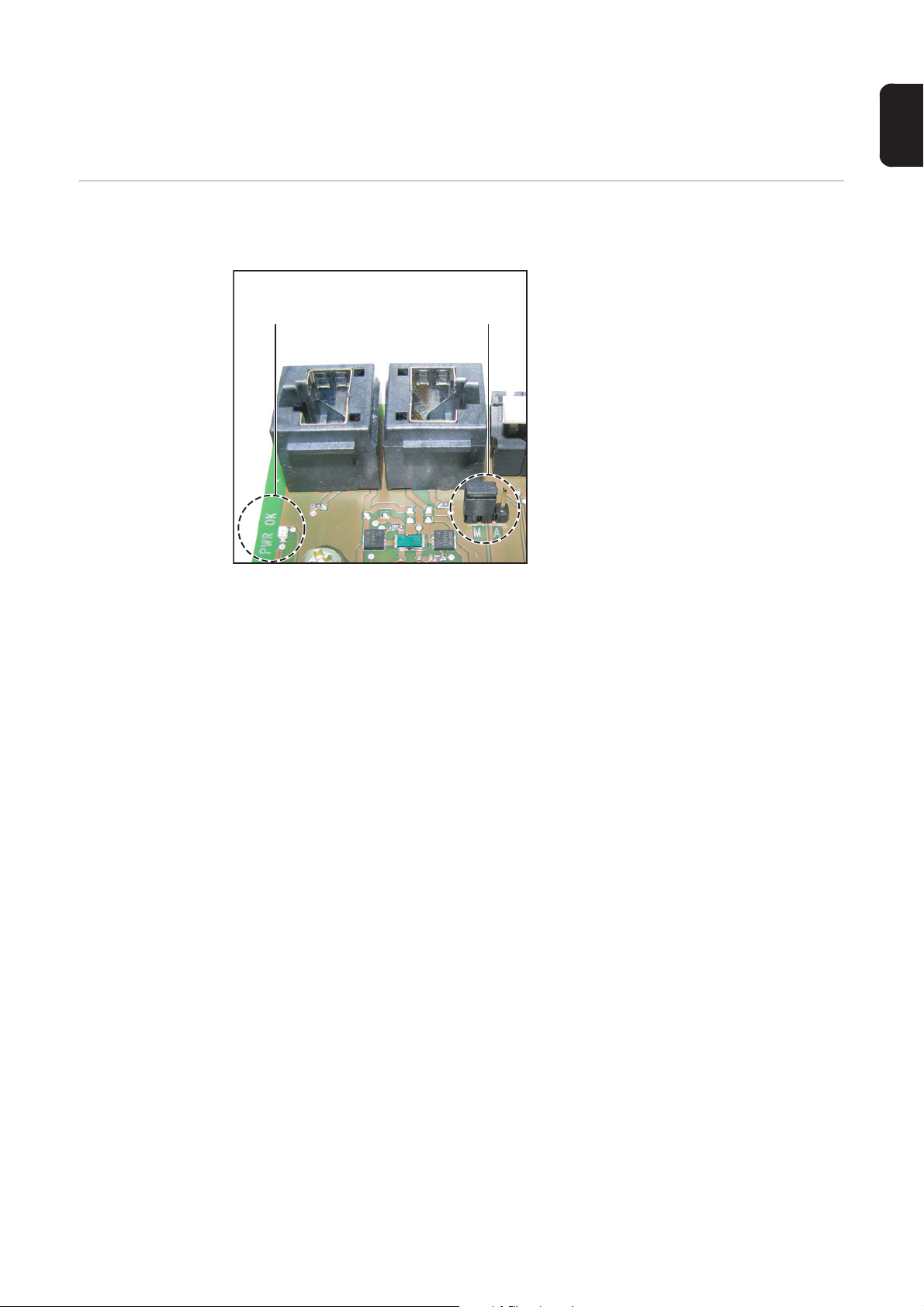
Jumper-Positionen:
(1)(2)
A automatisches Wiederherstellen
der Energieversorgung
(Werkseinstellung)
M manuelles Wiederherstellen der
Energieversorgung
32
Für das automatische Wiederherstellen der Energieversorgung muss der Jumper (1) auf
Position A gesetzt sein.
- Nach einer Abschaltung auf Grund Überstrom oder Unterspannung versucht die
Fronius String Control 100/12 alle 5 Sekunden die Energieversorgung im Solar Net
wieder herzustellen, solange z.B. der Kurzschluss anliegt.
- Die LED ‘PWROK’ (2) blinkt dabei alle 5 Sekunden kurz auf.
- Bei aufrechter Stromversorgung leuchtet die LED ‘PWROK’ grün.
Page 35
Wenn kein Kurzschluss anliegt und die LED ‘PWROK’ nicht leuchtet, liegt eine Abschaltung auf Grund Unterspannung vor.
In diesem Fall ist eine externe Energieversorgung der DATCOM-Komponenten mittels externem Netzteil erforderlich.
DE
Energieversorgung manuell
wiederherstellen
Das manuelle Wiederherstellen der Energieversorgung unterstützt den Installateur bei der
Fehlersuche und Fehlerbehebung im Fronius Solar Net.
Jumper-Positionen:
(1)(2)
A automatisches Wiederherstellen
der Energieversorgung
(Werkseinstellung)
B manuelles Wiederherstellen der
Energieversorgung
Für das manuelle Wiederherstellen der Energieversorgung muss der Jumper (1) auf Position M gesetzt sein.
- Nach einer Abschaltung auf Grund von Überstrom oder Unterspannung gibt es 2 Möglichkeiten, die Energieversorgung manuell wiederherzustellen:
a) Datenkommunikations-Kabel vom RJ45 Anschluss IN und OUT abstecken und
wieder anstecken
oder
mehradrige Datenkommunikations-Kabel von den Anschlussklemmen IN und
OUT abschließen und wieder anschließen;
Falls vorhanden, Kabel für eine externe Energieversorgung abstecken
b) die LED ‘PWROK’ für 0,5 - max. 2 Sekunden abdunkeln (z.B. Finger darüber
halten)
Damit die LED ‘PWROK’ das Abdunkeln erkennt, ist eine gewisse Umgebungshelligkeit erforderlich. Reichen die Lichverhältnisse vor Ort nicht aus, reagiert
die LED nicht. In diesem Fall die LED z.B. mit einer Taschenlampe anleuchten
und dann abdunkeln.
- Bei aufrechter Stromversorgung leuchtet die LED ‘PWROK’ grün.
Wenn kein Kurzschluss anliegt und die LED ‘PWROK’ nicht leuchtet, liegt eine Abschaltung auf Grund von Unterspannung vor.
In diesem Fall ist eine externe Energieversorgung der DATCOM-Komponenten mittels externem Netzteil erforderlich.
33
Page 36

Externe Energieversorgung anschließen
5
Allgemeines Die Energieversorgung der Fronius String Control 100/12 erfolgt über das Solar Net.
In Verbindung mit zusätzlichen DATCOM-Komponenten oder wenn die Datenkommunikations-Kabel eine Länge von 100 m überschreiten, kann die Energieversorgung über das
Solar Net nicht mehr ausreichen. Für diesen Fall ist ein externes Netzteil vefügbar.
Aus Zugänglichkeitsgründen empfiehlt Fronius, das externe Netzteil nach Möglichkeit an
einer anderen DATCOM-Komponente als der Fronius String Control 100/12 anzuschließen.
Sollte dennoch keine einfachere Anschlussmöglichkeit vorhanden sein, beschreibt die folgende Arbeitsanweisung das Anschließen des externen Netzteils an der Fronius String
Control 100/12.
Sicherheit
Externe Energieversorgung anschließen
WARNUNG! Ein elektrischer Schlag kann tödlich sein. Gefahr durch DC-Span-
nung von den Solarmodulen.
- Vor allen Anschlussarbeiten dafür sorgen, dass Eingangsseite und Ausgangsseite vor dem Gerät spannungsfrei sind!
- Sämtliche Anschlussarbeiten dürfen nur von lizenzierten Elektro-Installateuren durchgeführt werden!
- Beachten Sie die Sicherheitsvorschriften in dieser Bedienungsanleitung.
Metrische Verschraubung für die Datenkommunikations-Kabel lösen
1
Gummieinsatz herausnehmen
2
Netzteil-Kabel in die Fronius String Control 100/12 einführen
3
WICHTIG! Das Netzteil-Kabel muss wie die Datenkommunikations-Kabel durch einen Silikonschlauch geführt werden.
Netzteil-Kabel in den Silikonschlauch einführen
4
* Silikonschlauch Ø 14 x 420 mm
*
34
Page 37

Falls keine Öffnung im Gummieinsatz frei ist, zusätzliche Ausnehmung für das Netz-
8
6
teil-Kabel in den Gummieinsatz schneiden
Datenkommunikations-Kabel und Netzteil-Kabel in den Gummieinsatz einsetzen
7
Gummieinsatz mit den Kabeln in die metrische Verschraubung einsetzen
Metrische Verschraubung festziehen
9
DE
35
Page 38

Adresse einstellen
0XX
1XX
010
0XX
1XX
370
0XX
1XX
231
Sicherheit
WARNUNG! Ein elektrischer Schlag kann tödlich sein. Gefahr durch DC-Span-
nung von den Solarmodulen.
- Vor allen Anschlussarbeiten dafür sorgen, dass Eingangsseite und Ausgangsseite vor dem Gerät spannungsfrei sind!
- Sämtliche Anschlussarbeiten dürfen nur von lizenzierten Elektro-Installateuren durchgeführt werden!
- Beachten Sie die Sicherheitsvorschriften in dieser Bedienungsanleitung.
Allgemeines Das Solar Net ermöglicht den gleichzeitigen Betrieb von bis zu 200 Fronius String Control
100/12. Die Unterscheidung der einzelnen Fronius String Controls erfolgt durch Zuweisen
einer Adresse.
Das Einstellen der Adresse von 0 - 199 erfolgt am Adress-Schalter:
(1) Jumper für die Hunderter-Stelle
(2) Einstellrad für die Zehner-Stelle
(2) (3)
(1)
0XX
1XX
(3) Einstellrad für die Einer-Stelle
Adresse einstellen - Einstellbeispiele
36
Fronius String Control 100/12
Nr. 1
Fronius String Control 100/12
Nr. 37
Fronius String Control 100/12
Nr. 123
Page 39

Fronius String Control 100/12 schließen
1
DE
Sicherheit
Fronius String
Control 100/12
schließen
WARNUNG! Ein elektrischer Schlag kann tödlich sein. Gefahr durch DC-Span-
nung von den Solarmodulen.
- Vor allen Anschlussarbeiten dafür sorgen, dass Eingangsseite und Ausgangsseite vor dem Gerät spannungsfrei sind!
- Sämtliche Anschlussarbeiten dürfen nur von lizenzierten Elektro-Installateuren durchgeführt werden!
- Beachten Sie die Sicherheitsvorschriften in dieser Bedienungsanleitung.
Anzugsmoment = 3 Nm
3
2
1
6
4
5
37
Page 40

Einstellungen
(1)
(2)
(3)
Allgemeines Die Einstellungen für die Fronius String Control 100/12 erfolgen in der Software „Fronius
Solar.access“.
Erste Schritte - Software Fronius Solar.access am PC installieren
- Administration / Anlage anlegen
- Anlagen / [Name der Anlage] / Einstellungen / String Control
Mögliche Einstellungen für die
Fronius String
Control 100/12
Stränge pro
Messkanal
(1) Auswahl der Nummer (Adresse) der einzustellenden Fronius String Control 100/12
(2) Stränge pro Messkanal
(3) Grenzwerte:
- max. Ertragsabweichung in %
- Schwellwert in Ah pro Strang
Angabe der Anzahl an Solarmodul-Strängen für jeden Messkanal.
Dadurch erfolgt eine automatische Kompensation von Messkanal-Abweichungen, die auf
Grund einer unterschiedlichen Strangzahl pro Messkanal bedingt wären.
38
Page 41

Max. Ertragsabweichung
Schwellwert Die durchschnittliche Strommenge aller Stränge in Ah, ab der die Auswertung der „Max.
Die 2 Messkanäle erfassen über den ganzen Einspeisetag den Gesamtstrom der jeweils
angeschlossenen Solarmodul-Stränge. Am Abend bildet die Fronius String Control 100/12
den Mittelwert aller Messkanäle und vergleicht den Strom jedes Messkanals mit dem Mittelwert aller Messkanäle. Registriert die Fronius String Control 100/12 eine Abweichung
eines Messkanals von diesem Mittelwert, wird eine Statusmeldung an den Fronius Datalogger ausgegeben.
Im Eingabefeld „Max. Ertragsabweichung“ definieren Sie, ab welcher Abweichung in % ein
Messkanal als fehlerhaft eingestuft werden soll.
Richtwert für die max. Ertragsabweichung: 5 - 10 %
Gegebenenfalls die Angaben des Solarmodul-Herstellers beachten.
Ertragsabweichung“ aktiv sein soll.
Dadurch vermeiden Sie mögliche Statusmeldungen bei Schlechtwetter.
DE
39
Page 42

Anzeige der Daten und Statusmeldungen
Anzeige der Daten
Die aktuellen Daten der Fronius String Control 100/12 werden angezeigt unter:
Anlagen / [Name der Anlage] / Aktuell / String Control
Statusmeldungen Von der Fronius String Control 100/12 generierte Statusmeldungen gelangen an den Da-
tenlogger. Der Datenlogger verfährt dabei wie bei einer vom Wechselrichter generierten
Statusmeldung. Ein Versenden der Statusmeldungen als SMS, Fax oder E-Mail ist möglich. Näheres dazu entnehmen Sie der Bedienungsanleitung DATCOM Detail.
Die Servicecodes der Fronius String Control 100/12 lauten State 901 bis 902. Diese Sevicecodes beschreiben eine unzulässige Abweichung der Messkanäle 1 und 2.
Empfehlenswert ist das Aktivieren des Ertragsvergleichs im Menü „Einstellungen - Allgemein“. Damit erhalten Sie eine Liste mit Servicemeldungen, nach jedem Download vom
Datenlogger zum PC. Diese Liste verschafft Ihnen einen raschen Überblick aller Meldungen des Wechselrichters und der Fronius String Control 100/12.
40
Page 43

Statusdiagnose und Fehlerbehebung
(1)
DE
Sicherheit
Statusdiagnose
und Fehlerbehebung
WARNUNG! Ein elektrischer Schlag kann tödlich sein. Gefahr durch DC-Span-
nung von den Solarmodulen.
- Vor allen Anschlussarbeiten dafür sorgen, dass Eingangsseite und Ausgangsseite vor dem Gerät spannungsfrei sind!
- Sämtliche Anschlussarbeiten dürfen nur von lizenzierten Elektro-Installateuren durchgeführt werden!
- Beachten Sie die Sicherheitsvorschriften in dieser Bedienungsanleitung.
90x
vom Datenlogger mitgeloggte oder je nach Einstellung verschickte Servicecodes der
Fronius String Control 100/12
x ... bezeichnet den Messkanal
Ursache: unzulässige Abweichung eines Messkanals vom eingestellten
Wert
x = 1 ... Messkanal 1
x = 2 ... Messkanal 2
Behebung: Strangsicherungen überprüfen, Solarmodul-Stränge überprü-
fen, Einstellungen in der Software Fronius Solar.access überprüfen
Fehlende Logging-Daten während des Tages
Ursache: Solar Net ist offen (die LED ‘Verbindung’ am Datalogger leuch-
tet rot)
Behebung: - Jumper auf manuelle Wiederherstellung der Energiever-
sorgung umsetzen
- Leitungen, Anschlüsse und Versorgung überprüfen:
der Fehler ist ab der ersten Fronius String Control 100/12
in OUT-Richtung zu finden, bei der die LED ‘X’ (1) rot
leuchtet oder keine Stromversorgung vorhanden ist
41
Page 44

Strangsicherungen tauschen, Wartung
3
Sicherheit
Vorbereitung Verbindung zu den AC-Zuleitungen mittels AC-Trenneinrichtung für den Wechselrich-
1
2
3
4
5
6
7
WARNUNG! Fehlerhaft durchgeführte Arbeiten können schwerwiegende Sachund Personenschäden verursachen. Nachfolgend beschriebene Tätigkeiten dürfen nur von geschultem Fachpersonal durchgeführt werden! Beachten Sie die Sicherheitsvorschriften in dieser Bedienungsanleitung.
WARNUNG! Ein elektrischer Schlag kann tödlich sein. Gefahr durch DC-Spannung von den Solarmodulen.
- Vor allen Wartungsarbeiten dafür sorgen, dass Eingangsseite und Ausgangsseite vor dem Gerät spannungsfrei sind!
- Sicherungen nicht unter Last wechseln!
ter unterbrechen
Solarmodul-Stränge zur Fronius String Control 100/12 unterbrechen
Ein deutlich lesbares und verständliches Warnschild gegen Wiedereinschalten und
Wiederzusammenführen von geöffneten / unterbrochenen Verbindungen anbringen
Solarmodul-Stränge auf Spannungsfreiheit überprüfen
Solarmodul-Stränge kurzschließen
Deckel abmontieren
Sicherungshalter an den Klemmen auf Durchgang überprüfen
Strangsicherungen tauschen
HINWEIS! Zur Absicherung der Solarmodule ausschließlich Sicherungen ver-
wenden, die den Kriterien zur richtigen Sicherungsauswahl entsprechen.
Sicherungsdimensionen: Durchmesser 10 x 38 mm
1
Ursache für defekte Sicherung eruieren und beheben
2
42
Page 45

Abschließende
3
Tätigkeiten
Deckel montieren
1
Kurzschluss der Solarmodul-Stränge aufheben
2
Solarmodul-Stränge zur Fronius String Control 100/12 schließen
Verbindung zu den AC-Zuleitungen mittels AC-Trenneinrichtung für den Wechselrich-
4
ter wieder herstellen
DE
Wartung
HINWEIS! Bei horizontaler Montagelage:
sämtliche Verschraubungen jährlich auf festen Sitz überprüfen!
43
Page 46

44
Page 47

Dear reader,
Introduction Thank you for the trust you have placed in our company and congratulations on buying this
high-quality Fronius product. These instructions will help you familiarize yourself with the
product. Reading the instructions carefully will enable you to learn about the many different
features it has to offer. This will allow you to make full use of its advantages.
Please also note the safety rules to ensure greater safety when using the product. Careful
handling of the product will repay you with years of safe and reliable operation. These are
essential prerequisites for excellent results.
EN-US
Safety Rules Explanation
DANGER! Indicates an imminently hazardous situation which, if not avoided, will
result in death or serious injury.
WARNING! Indicates a potentially hazardous situation which, if not avoided, will
result in death or serious injury.
CAUTION! Indicates a potentially harmful situation which, if not avoided, may result in minor and moderate injury or property damage.
NOTE! Indicates a risk of flawed results and possible damage to the equipment.
IMPORTANT! Indicates tips for correct operation and other particularly useful information.
It does not indicate a potentially damaging or dangerous situation.
If you see any of the symbols depicted in the "Safety rules," special care is required.
45
Page 48

46
Page 49

Contents
Safety rules ................................................................................................................................................ 49
General ...................................................................................................................................................... 52
Device concept ..................................................................................................................................... 52
Functional principle............................................................................................................................... 52
Inverter.................................................................................................................................................. 52
Other System Requirements................................................................................................................. 52
Intended Use......................................................................................................................................... 52
Scope of Supply.................................................................................................................................... 53
Optional................................................................................................................................................. 53
Technical data....................................................................................................................................... 53
Abbreviations and Descriptions Used ................................................................................................... 54
Warning notices affixed to the device ................................................................................................... 54
Product description .................................................................................................................................... 56
Safety.................................................................................................................................................... 56
Device description, housing .................................................................................................................. 56
Device description, inside of device...................................................................................................... 57
Installing Metric Screw Joints on the Fronius String Control 100/12.......................................................... 58
General ................................................................................................................................................. 58
Recommended Sequence for Inserting the Metric Screw Joints .......................................................... 58
Installing Metric Screw Joints................................................................................................................ 58
Tightening torques for metric screw joints ............................................................................................ 59
Installing the Fronius String Control 100/12............................................................................................... 60
Selecting dowels and screws................................................................................................................ 60
Selecting a Location.............................................................................................................................. 60
Installation position ............................................................................................................................... 61
Fronius String Control 100/12 Installation............................................................................................. 61
Connecting Solar Module Strings to the Fronius String Control 100/12 .................................................... 63
Safety.................................................................................................................................................... 63
Notes for Connecting Solar Module Strings to the Fronius String Control 100/12 ............................... 63
Terminal assignment for grounded solar modules................................................................................ 64
Example of terminal assignment for grounded solar modules .............................................................. 64
Connecting Solar Module Strings to the Fronius String Control 100/12 .............................................. 64
Final Tasks ........................................................................................................................................... 65
Connecting the Fronius String Control 100/12 to the Inverter....................................................................66
Safety.................................................................................................................................................... 66
Preparation ........................................................................................................................................... 66
Connecting the Fronius String Control 100/12 to the Inverter............................................................... 67
Criteria for the Proper Selection of String Fuses ....................................................................................... 68
General ................................................................................................................................................. 68
Criteria for the Proper Selection of String Fuses .................................................................................. 68
Effects of Using Underrated Fuses ....................................................................................................... 68
Fuse recommendations ........................................................................................................................ 68
Fuse Recommendations - Application Example ................................................................................... 69
Fuses .................................................................................................................................................... 69
Inserting String Fuses ................................................................................................................................ 70
Safety.........................................................................................................................
ing string fuses............................................................................................................................ 70
Select
Inserting String Fuses........................................................................................................................... 70
Connecting Data Communication Cable to the Fronius String Control 100/12 .......................................... 71
Connection Options .............................................................................................................................. 71
Additional Insulation for Data Communication Cables.......................................................................... 71
Configuration example.......................................................................................................................... 72
Safety.................................................................................................................................................... 72
Connecting RJ 45 Data Communication Cables to the Fronius String Control 100/12......................... 73
Connecting Multicore Data Communication Cables to the Fronius String Control 100/12 ................... 74
Overcurrent and Under-voltage Shutdown ................................................................................................ 76
General ................................................................................................................................................. 76
Functional principle............................................................................................................................... 76
Safety.................................................................................................................................................... 76
Restoring the energy supply automatically ........................................................................................... 76
........................... 70
EN-US
47
Page 50

Restoring the energy supply manually.................................................................................................. 77
Connecting an External Power Supply ...................................................................................................... 78
General ................................................................................................................................................. 78
Safety.................................................................................................................................................... 78
Connecting an External Power Supply ................................................................................................. 78
Setting the Address.................................................................................................................................... 80
Safety.................................................................................................................................................... 80
General ................................................................................................................................................. 80
Setting the Address - Examples............................................................................................................ 80
Closing the Fronius String Control 100/12 ................................................................................................. 81
Safety.................................................................................................................................................... 81
Closing the Fronius String Control 100/12 ............................................................................................ 81
Settings ...................................................................................................................................................... 82
General ................................................................................................................................................. 82
Initial Steps ........................................................................................................................................... 82
Possible Settings for the Fronius String Control 100/12 ....................................................................... 82
Strings per Measuring Channel ............................................................................................................ 82
Max. Energy Deviation.......................................................................................................................... 83
Threshold.............................................................................................................................................. 83
Display of Data and Status Messages ....................................................................................................... 84
Data Display.......................................................................................................................................... 84
Status Messages .................................................................................................................................. 84
Status Diagnosis and Troubleshooting ...................................................................................................... 85
Safety.................................................................................................................................................... 85
Status diagnosis and troubleshooting ................................................................................................... 85
Replacing String Fuses, Maintenance ....................................................................................................... 86
Safety.................................................................................................................................................... 86
Preparation ........................................................................................................................................... 86
Replacing String Fuses......................................................................................................................... 86
Finally.................................................................................................................................................... 87
Maintenance ......................................................................................................................................... 87
48
Page 51

Safety rules
General
The device is manufactured using state-of-the-art technology and according
to recognized safety standards. If used incorrectly or misused, however, it can
cause
- injury or death to the operator or a third party,
- damage to the device and other material assets belonging to the operator,
- inefficient operation of the device
All persons involved in commissioning, maintaining and servicing the device
must
- be suitably qualified,
- have knowledge of and experience in dealing with electrical installations
and
- read and follow these operating instructions carefully
The operating instructions must always be at hand wherever the device is being used. In addition to the operating instructions, attention must also be paid
to any generally applicable and local regulations regarding accident prevention and environmental protection.
All safety and danger notices on the device
- must be kept in a legible state
- must not be damaged/marked
- must not be removed
- must not be covered, pasted or painted over
For the location of the safety and danger notices on the device, refer to the
section headed "General" in the operating instructions for the device.
Before switching on the device, remove any faults that could compromise
safety.
Your personal safety is at stake!
EN-US
Utilization in Accordance with
"Intended Purpose"
Environmental
Conditions
The device is to be used exclusively for its intended purpose.
Utilization for any other purpose, or in any other manner, shall be deemed to
be "not in accordance with the intended purpose." The manufacturer shall not
be liable for any damage resulting from such improper use.
Utilization in accordance with the "intended purpose" also includes
- carefully reading and obeying all the instructions and all the safety and
danger notices in the operating instructions
- performing all stipulated inspection and servicing work
- installation as specified in the operating instructions
The following guidelines should also be applied where relevant:
- Regulations of the utility regarding energy fed into the grid
- Instructions from the solar module manufacturer
Operation or storage of the device outside the stipulated area will be deemed
as "not in accordance with the intended purpose." The manufacturer is not responsible for any damages resulting from unintended use.
For exact information on permitted environmental conditions, please refer to
the "Technical data" in the operating instructions.
49
Page 52
Qualified Service
Engineers
The servicing information contained in these operating instructions is intended
only for the use of qualified service engineers. An electric shock can be fatal.
Do not perform any actions other than those described in the documentation.
This also applies to those who may be qualified.
All cables and leads must be secured, undamaged, insulated and adequately
dimensioned. Loose connections, scorched, damaged or inadequately dimensioned cables and leads must be immediately repaired by authorized personnel.
Maintenance and repair work must only be carried out by authorized personnel.
It is impossible to guarantee that externally procured parts are designed and
manufactured to meet the demands made on them, or that they satisfy safety
requirements. Use only original replacement parts (also applies to standard
parts).
Do not carry out any modifications, alterations, etc. without the manufacturer's
consent.
Components that are not in perfect condition must be changed immediately.
Safety Measures
at the Installation
Location
EMC Device Classifications
EMC Measures
When installing devices with openings for cooling air, ensure that the cooling air can enter
and exit unhindered through the vents. Only operate the device in accordance with the degree of protection shown on the rating plate.
Devices in emission class A:
- Are only designed for use in industrial settings
- Can cause line-bound and radiated interference in other areas
Devices in emission class B:
- Satisfy the emissions criteria for residential and industrial areas.
This is also true for residential areas in which the energy is supplied from the public low-voltage grid.
EMC device classification as per the rating plate or technical data.
In certain cases, even though a device complies with the standard limit values
for emissions, it may affect the application area for which it was designed (e.g.,
when there is sensitive equipment at the same location, or if the site where the
device is installed is close to either radio or television receivers). If this is the
case, then the operator is obliged to take appropriate action to rectify the situation.
Electrical Installations
50
Electrical installations must only be carried out according to relevant national
and local standards and regulations.
Page 53

Protective Measures against
ESD
Safety Measures
in Normal Operation
Danger of damage to electrical components from electrical discharge. Suitable
measures should be taken to protect against ESD when replacing and installing components.
EN-US
Only operate the device when all protection devices are fully functional. If the
protection devices are not fully functional, there is a risk of
- injury or death to the operator or a third party,
- damage to the device and other material assets belonging to the operator,
- inefficient operation of the device
Any safety devices that are not functioning properly must be repaired by au-
thorized personnel before the device is switched on.
Never bypass or disable protection devices.
Safety Symbols
Disposal
Backup
Devices with the CE marking satisfy the essential requirements of the low-voltage and electromagnetic compatibility directives. Further details can be found
in the appendix or the chapter entitled "Technical data" in your documentation.
Do not dispose of this device with normal domestic waste! To comply with the
European Directive 2002/96/EC on Waste Electrical and Electronic Equipment and its implementation as national law, electrical equipment that has
reached the end of its life must be collected separately and returned to an approved recycling facility. Any device that you no longer require must be returned to your dealer, or you must locate the approved collection and recycling
facilities in your area. Ignoring this European Directive may have potentially
adverse affects on the environment and your health!
The user is responsible for backing up any changes made to the factory settings. The manufacturer accepts no liability for any deleted personal settings.
Copyright
Copyright of these operating instructions remains with the manufacturer.
Text and illustrations are technically correct at the time of going to print. The
right to make modifications is reserved. The contents of the operating instruc-
tions shall not provide the basis for any claims whatsoever on the part of the
purchaser. If you have any suggestions for improvement, or can point out any
mistakes that you have found in the operating instructions, we will be most
grateful for your comments.
51
Page 54

General
Device concept The Fronius String Control 100/12 is designed for use in grid-connected photovoltaic sys-
tems with several solar module strings.
Up to max. 12 solar module strings can be combined at the input to the Fronius String Control 100/12, in order to reduce these to one DC+ and DC- main line at the output.
The Fronius String Control 100/12 monitors the incoming solar module strings in order to
identify errors in the solar module field.
Status messages can be sent via e-mail or SMS when using Fronius system monitoring
(e.g. Solar.web, etc.) and a Fronius Datalogger. This allows a defective solar module to be
detected quickly.
Functional principle
Inverter The Fronius String Control 100/12 is designed exclusively for use with the following invert-
Other System Requirements
- Each set of 6 incoming solar module strings is grouped into one measuring channel.
- 2 measuring channels record the total current of the respective connected solar module strings over the entire charging day.
- In the evening, the Fronius String Control 100/12 calculates an average value for all
measuring channels.
- The Fronius String Control 100/12 compares the current of each measuring channel
with the average value of all measuring channels.
- If the Fronius String Control 100/12 detects that one of the measuring channels deviates too much from the average, a status message is sent to the Fronius Datalogger.
- The permitted deviation from the average is freely definable.
ers:
- Fronius IG 300 / 390 / 400 / 500
- Fronius IG Plus / Fronius IG Plus V
- Fronius CL
- Fronius Datalogger
- Fronius system monitoring
- PC with Fronius Solar.access software installed
- or PC with Internet connection and access to Fronius Solar.web
Intended Use The device is intended solely for use as a collector and measuring device for the solar mod-
ule DC strings. Use of the device is permitted only in conjunction with an inverter which
complies with the legal requirements at the place of installation.
Any other purpose does not constitute intended use. The manufacturer shall not be liable
for any damage resulting from such improper use.
Intended use also includes following all information from the operating instructions.
52
Page 55

Scope of Supply - 1 Fronius String Control 100/12 (in the metal housing)
- 2 M32 metric screw joints including counter nuts
- 24 M16 metric screw joints including counter nuts
- 10 M16 threaded plugs
- 1 M20 metric screw joint including counter nut
- 1 M20 metric threaded plug
- 1 M25 metric screw joint including counter nut
- 1 M25 rubber insert
- 2 plastic bolts
- 1 silicone tube Ø 25 x 510 mm (for data communication cable)
- 1 silicone tube Ø 14 x 420 mm (for external power supply)
- 1 Set of seals (24 O-rings M16, 2 O-rings M32, 2 O-rings M20/M25)
- 1 DC Connector Kit (2 connection distributors including assembly accessories)
- 1 fire prevention leaflet
- 1 installation leaflet
Optional If type 1 or type 2 overvoltage protection is desired, it can be installed in the Fronius String
Control 100/12 on the DIN rail provided for this purpose.
EN-US
Technical data
Max. input voltage in no-load operation 600 V
Max. input current 100 A
Max. input current per fuse holder 20 A
Max. number of strings (with integrated solar module fuse) 12
Max. cable cross section for terminals on the solar module side 10 mm² *)
Max. cable cross section for the M12 connections on the invert-
er side
Number of measuring channels 2
Max. current per measuring channel 50 A
Screw joint for cable attachment to the solar module side M16
Screw joint for cable attachment to the inverter side M32
Degree of protection IP 55
Ambient conditions -25 °C - +60 °C
-13 °F - +140 °F
Dimensions (without screw joints) 500 x 350 x 145 mm
19.7 x 13.8 x 5.7 in.
DATCOM power supply via Solar Net
optional via a 12 V power supply
Max. Solar Net current consumption 110 mA
Weight 6,2 kg
*) applies for single and multi-core cables:
10 mm² with maximum cable diameter of 7 mm
95 mm²
13.67 lbs.
53
Page 56

Abbreviations
and Descriptions
Used
DC cable 'OUT' DC output cable from Fronius String Control 100/12 to inverter;
the polarity of the DC cable ‘OUT’ depends on how the solar
module strings are connected to the Fronius String Control 100/
12.
DC cable 'IN' Solar module strings from the solar modules to the Fronius
String Control 100/12;
one solar module consists of one DC+ cable and one DC- cable.
Warning notices
affixed to the device
The Fronius String Control 100/12 contains warning notices and safety symbols. These
warning notices and safety symbols must NOT be removed or painted over. The notices
and symbols warn against operating the equipment incorrectly, as this may result in serious injury and damage.
Safety Symbols:
Danger of serious injury or damage due to incorrect operation
Do not use the functions described until you have thoroughly read and understood the following documents:
- These operating instructions
- all operating instructions for system components of the photovoltaic system, especially the safety rules
Dangerous electrical voltages
54
Page 57

Text of warning notices:
WARNING!
An electric shock can be fatal.
Danger from DC voltage from solar modules.
More than one power source.
Disconnect all power sources before maintenance work.
Before opening the device, ensure that the input and output sides in front of the device are
not charged!
Dangerous voltage caused by solar modules exposed to light.
The connection area must only be opened by qualified electricians.
EN-US
55
Page 58

Product description
(8)
(9) (9) (9)
(9)(9)(9)
Safety
Device description, housing
WARNING! Operating the device incorrectly can cause serious injury and dam-
age. Do not use the functions described until you have thoroughly read and understood the following documents:
- these operating instructions
- all operating instructions for system components, especially the safety rules
(1) (2) (3)
(4)(5)(6)(7)
Fronius String Control 100/12 – front view Fronius String Control 100/12 – oblique view from abo-
ve
Item Description
(1) Cable input for M16 metric screw joints
(for DC cable‘IN’)
Cable diameter 3 - 7 mm
(2) Cable input for M16 metric screw joints
(for DC cable‘IN’)
Cable diameter 3 - 7 mm
(3) Cable input for M25 metric screw joint
(for data communication cable)
(4) Pressure compensation membrane
(5) Cable input for M32 metric screw joint
(for DC cable‘OUT’)
Cable diameter 11 - 21 mm
(6) Cable input for M32 metric screw joint
(for DC cable‘OUT’)
Cable diameter 11 - 21 mm
(7) Cable input for M20 metric screw joint
(for ground cable)
Cable diameter 8 - 13 mm
56
Only required when using the optional overvoltage protection.
(8) Cover
(9) Cover screw
Page 59

Device descrip-
(1) (2) (3) (4) (5) (6) (8)(7)
(12) (9)(10)(11)
tion, inside of device
IMPORTANT! Metric screw joints and threaded plugs are not installed on the Fronius
String Control 100/12 when delivered. They are just included in the scope of supply.
EN-US
Fronius String Control 100/12 – inside of device
Item Description
(1) DIN rail
for installing a conventional overvoltage protection
(2) Measuring Channel 1
(3) RJ 45 connections for data communication cable
(4) Terminals for data communication cable
Cable cross section max. 2.5 mm²
(5) Terminals for data communication cable
Cable cross section max. 2.5 mm²
(6) Address switch
(7) Connection for external 12 V DC power supply
(8) Measuring channel 2
(9) Terminals with fuse holders for DC cable ‘IN‘
Cable cross section 2.5 - 10 mm² *)
(10) M12 connection for DC cable 'OUT'
(11) M12 connection for DC cable 'OUT'
(12) Terminals for DC cable ‘IN‘
Cable cross section 2.5 - 10 mm² *)
*) applies for single and multi-core cables:
10 mm² with maximum cable diameter of 7 mm
57
Page 60

Installing Metric Screw Joints on the Fronius String
M16
M32 M32
M20 *
M16
12 13
14
M16
1
2
3
4
5
6
7
8
9
10
11 15
M25
M16
M16
M16
16
171819
20
21
22
23
24
25
26
27
28
2
4
Control 100/12
General - Insert metric screw joints corresponding to the number of available solar module
strings, insert threaded plugs in the empty positions.
- Observe the sequence when inserting metric screw joints:
from bottom to top and from left to right.
- Attach O-rings corresponding to their size to the metric screw joints.
- Use the specified tightening torque corresponding to their size for the metric screw
joints and threaded plugs.
Recommended
Sequence for Inserting the Metric
Screw Joints
Installing Metric
Screw Joints
* only when using optional overvoltage protection as outlet for the ground cable
1
Opening the Fronius String Control 100/12 Installing Metric Screw Joints:
2
1 Counter nut
2 O-ring
3 Screw joint
4 Strain-relief device
58
Page 61

Tightening
torques for metric
screw joints
Size Counter nut / screw joint Screw joint / strain-relief device
M16 3.0 Nm 2.0 Nm
M20 6.0 Nm 4.0 Nm
M25 8.0 Nm 5.0 Nm
M32 10.0 Nm 6.5 Nm
The screw joint is placed on the inside of the Fronius String Control 100/12.
The tightening torque for the strain-relief device is valid for connected cables.
EN-US
59
Page 62

Installing the Fronius String Control 100/12
Selecting dowels
and screws
Selecting a Location
Depending on the surface, different dowels and screws may be required for installing the
Fronius String Control 100/12. Therefore, these dowels and screws are not part of the
scope of supply for the Fronius String Control 100/12. The system installer is responsible
for selecting the proper dowels and screws.
When selecting the location, please observe the following criteria:
- Install only on a solid and level surface
- The ambient temperature may not fall below -25°C nor exceed +60°C.
- The Fronius String Control 100/12 may be installed outside in sheltered areas. Avoid
direct contact with moisture.
- Protect from direct sunlight and direct exposure to the elements.
- Install under the solar modules where possible.
NOTE! To prevent warping of the
Fronius String Control 100/12, the
device should be installed only on
a flat surface.
60
Page 63

Installation posi-
0-90°
2
tion
The Fronius String Control 100/12 can be installed in any position
between the horizontal and vertical.
For vertical and inclined installation position, the cable entries and
outlets must always be positioned pointing downwards.
EN-US
Fronius String
Control 100/12 Installation
NOTE! The installation of the Fronius DC Box 60/12 shall be done at the appro-
priate mounting brackets only.
Under no circumstances drill holes into the housing!
1
3
4
61
Page 64

5
62
Page 65

Connecting Solar Module Strings to the Fronius
1
2
3
4
56
7
89101112
1234
56 78
9101112
String Control 100/12
Safety
Notes for Connecting Solar
Module Strings to
the Fronius String
Control 100/12
WARNING! An electric shock can be fatal. Danger from DC voltage from solar
modules.
- Make sure that the input and output sides in front of the device are not
charged before connecting anything.
- Any and all connections should only be carried out by qualified electricians.
- Follow the safety rules in these operating instructions.
NOTE! Only use a DC cable with the correct polarity at
the terminals for DC cable 'IN' and at the terminals with
fuse holders for DC cable 'IN'.
NOTE! To ensure problem-free DC cable connections to the terminals, the length
of the DC cables should be no less than 330 mm (measured from the inside bottom edge of the Fronius String Control 100/12).
NOTE! Observe the sequence when inserting and connecting DC cables: from
bottom to top and from the inside outwards.
EN-US
Recommended sequence for inserting and connecting DC cables
NOTE! When connecting fewer than 12 solar module strings, we recommend assigning the DC cables to the measuring channels as equally as possible.
For example: When connecting 8 solar module strings, connect 4 DC cables per
measuring channel. If possible, leave individual terminals free between the DC
cables.
NOTE! When connecting solar modules with varying power tolerance, we recommend distributing the power to the measuring channels as equally as possible.
63
Page 66

Terminal assign-
(B)(A)
(
B‘)(A‘)
+
-
(A)
(C)
ment for grounded solar modules
For grounded solar modules, only the ungrounded poles of the solar module strings may
be connected to the fuse-protected terminals (A).
Example of terminal assignment
for grounded solar modules
Negative solar module ground
Positive solar module ground
-
(B)(A)
B‘)(A‘)
(
+
DC- DC+
B (in) B‘ (out) A‘ (out) A (in)
DC+ DC-
B (in) B‘ (out) A‘ (out) A (in)
Connecting Solar
Module Strings to
the Fronius String
Control 100/12
Assignment for solar module ground at the negative
pole
1
(B)
(A)
(A) Tightening torque 2.0 Nm
Assignment for solar module ground at the positive
pole
2
64
(B) Tightening torque 1.5 Nm
(C) Tightening torque 2.0 Nm
Page 67

Final Tasks
NOTE!
- Make the solar module DC cables outside the equipment into a loop.
- Ensure there is enough support for the cable so that the equipment must not
bear the whole weight.
EN-US
DC IN
Cable loop in vertical installation position
DC IN
Cable loop in horizontal installation position
65
Page 68

Connecting the Fronius String Control 100/12 to the
1
3
(B)
(A)
5
6
Inverter
Safety
Preparation
WARNING! An electric shock can be fatal. Danger from DC voltage from solar
modules.
- Make sure that the input and output sides in front of the device are not
charged before connecting anything.
- Any and all connections should only be carried out by qualified electricians.
- Follow the safety rules in these operating instructions.
2
2
M12
1
M12
3
4
M12
DC cable ‘OUT‘
3
(A) Tightening torque 28 Nm
(B) Tightening torque 6 Nm
NOTE! Label the DC cable 'OUT' according to its designated polarity.
66
Page 69

Connecting the
Fronius String
Control 100/12 to
the Inverter
Connect the DC cable 'OUT' to the inverter as per the inverter operating instructions
1
NOTE! Note the following points when connecting:
- Is a solar module ground required or present?
If yes, keep in mind the special features of the relevant solar module ground
- If there is a solar module ground present, Fronius recommends that you always insert string fuses into the non-grounded branch.
- Connect the DC cable 'OUT' to the inverter with the correct polarity
EN-US
67
Page 70

Criteria for the Proper Selection of String Fuses
General You can give Solar modules extra protection by using string fuses in the String Control 100/
12.
Crucial for the fuse protection of the solar modules is the maximum short circuit current I
of the relevant solar module.
sc
Criteria for the
Proper Selection
of String Fuses
Effects of Using
Underrated Fuses
The following criteria must be met for each solar module string when using fuse protection:
-I
-IN < 2.4 x I
> 1.8 x I
N
SC
SC
-UN >/= max. Input voltage of the inverter used:
Fronius CL 36.0 / 48.0 / 60.0 etc. 600 V DC
Fronius IG Plus / IG Plus V etc. 600 V
- Fuse dimensions: Diameter 10 x 38 mm
I
N
I
SC
Nominal current rating of the fuse
Short circuit current for standard test conditions (STC) according to solar module
data sheet
V
Nominal voltage rating of the fuse
N
NOTE! The nominal current value of the fuse must not exceed the maximum fuse
protection value specified in the solar module manufacturer's datasheet. If a maximum fuse protection value is not specified, please request it from the solar module manufacturer.
With underrated fuses, the nominal current value may be less than the short circuit current
of the solar module.
Effect:
The fuse may trip in intensive lighting conditions.
Fuse recommendations
68
NOTE! Always select fuses whose rated voltage is greater than or equal to the
maximum input voltage of the inverter used.
For total safety, always use the following fuses, which have been tested by Fronius:
- Littelfuse SPF fuses
Fronius shall not be liable, and all warranty claims shall be invalidated, for damage or other
incidents that are associated with the use of different fuses.
Page 71

Fuse Recommendations - Application Example
Example: Maximum short circuit current (ISC) of the solar module = 5.75 A
According to the criteria for selecting the right string fuses, the fuse must have a nominal
current greater than 1.5 times and less than 2.0-times the short circuit current:
- 5.75 A x 1.5 = 8.625 A
- 5.75 A x 2.0 = 11.5 A
EN-US
Fuse to be selected from the 'Fuses' table:
SPF9 with a nominal current of 9 A
or
SPF10 with a nominal current of 10 A.
Fuses
Nominal current Fuse Nominal current Fuse
4.0 A SPF 4 9.0 A SPF 9
5.0 A SPF 5 10.0 A SPF 10
6.0 A SPF 6 12.0 A SPF 12
7.0 A SPF 7 15.0 A SPF 15
8.0 A SPF 8 20.0 A SPF 20
'Fuses' table: Extract of suitable fuses, e.g. Littelfuse fuses
69
Page 72

Inserting String Fuses
Safety
Selecting string
fuses
WARNING! An electric shock can be fatal. Danger from DC voltage from solar
modules.
- Make sure that the input and output sides in front of the device are not
charged before connecting anything.
- Never remove or insert a fuse while it is under load.
- Any and all connections should only be carried out by qualified electricians.
- Follow the safety rules in these operating instructions.
Only use fuses for solar modules that meet the proper requirements for string fuses from
the solar module manufacturer or as per the "Criteria for the Proper Selection of String Fuses" section:
- max. 20 A per fuse holder
- max. 12 solar module strings
- max. 50 A per measuring channel
- max. 100 A of total input current
- Fuse dimensions: Diameter 10 x 38 mm
IMPORTANT!
- Follow all solar module safety instructions
- Follow all solar module manufacturer requirements
Inserting String
Fuses
NOTE! Insert string fuses in the fuse holders in accordance with the number of
available solar modules.
1
2
70
Page 73

Connecting Data Communication Cable to the Fronius String Control 100/12
Connection Options
There are two options for connecting the Fronius String Control 100/12 to Solar Net:
- via pre-assembled data communication cables with RJ 45 plugs
Cable recommendation:
cable size CAT 5, 1:1 cable
- via multi-core data communication cables
max. cable cross section 2.5 mm²
RJ 45 connections Spring terminals for connecting multi-core data com-
munication cables
EN-US
Additional Insulation for Data
Communication
Cables
IMPORTANT! A silicone tube is part of the scope of supply for the Fronius String Control
100/12 for additional data communication cable insulation.
When laying the data communication cables on the inside of the Fronius String Control
100/12, the data communication cables must be fed through the silicone tube.
71
Page 74

Configuration ex-
Line/ISDN
OUT
IN
OUTIN
(1) (2)
(3)
(4)
(4)
OUT
IN
IN 1 +12V
2GND
3Tx4Rx5Rx+
6Tx+
7GND
8+12V
OUT 1 +12V
2GND
3Rx4Tx5Tx+
6Rx+
7GND
8+12V
IN 1 +12V
2GND
3Tx4Rx5Rx+
6Tx+
7GND
8+12V
OUT 1 +12V
2GND
3Rx4Tx5Tx+
6Rx+
7GND
8+12V
IN 1 +12V
2GND
3Tx4Rx5Rx+
6 Tx+
7GND
8+12V
OUT 1 +12V
2GND
3Rx4Tx5 Tx+
6Rx+
7GND
8+12V
ample
Safety
72
(1) Inverter with Fronius Com Card
(2) Fronius String Control 100/12
(3) Fronius Datalogger
(4) Termination plug
WARNING! An electric shock can be fatal. Danger from DC voltage from solar
modules.
- Make sure that the input and output sides in front of the device are not
charged before connecting anything.
- Any and all connections should only be carried out by qualified electricians.
- Follow the safety rules in these operating instructions.
Page 75

Connecting RJ 45
5 Nm
2
1
3
Data Communication Cables to the
Fronius String
Control 100/12
1
2
EN-US
3
1
2
DATCOM IN
DATCOM OUT
3
* Silicone tube Ø 25 x 510 mm
NOTE! Procedure when only 1 data communication cable is being connected to
the Fronius String Control 100/12 (e.g., when the Fronius String Control 100/12
is the last component in a Solar Net):
- Insert the termination plug in the free RJ 45 connection. The termination plug
is part of the scope of supply for every Fronius Datalogger.
- Insert the plastic bolt in the free opening of the rubber insert (included in the
scope of supply for the Fronius String Control 100/12).
4
73
Page 76

Connecting Multi-
IN
OUT
+12 V
GND
TX-
RX-
RX+
TX+
GND
+12 V
+12 V
GND
RX-
TX-
TX+
RX+
GND
+12 V
core Data Communication
Cables to the Fronius String Control 100/12
When using multi-core data communication cables with a diameter up to a max. of 6 mm,
both cables are fed through the rubber insert and through the opening intended for this purpose like with the RJ 45 cable.
The following work steps are for data communication cables with a maximum diameter of
up to 6 mm.
Strip approx. 50 - 70 mm of insulation from the end of the data communication cable
1
2
3
2
* Silicone tube Ø 25 x 510 mm
IMPORTANT! You must know the assignment of each individual wire when connecting the
wires to the terminals.
3
Terminal assignments:
74
Page 77

4
NOTE! Procedure when only 1 multi-core data communication cable is being connected to the Fronius String Control 100/12 (e.g., when the Fronius String Control
100/12 is the last component in a Solar Net):
- If the data communication cable is connected to the "IN" terminals, connect
the termination plug to the "OUT" RJ 45 connection.
- If the data communication cable is connected to the "OUT" terminals, connect the termination plug to the "IN" RJ 45 connection.
Tightening torque 5 Nm
EN-US
The termination plug is included in the scope of supply of the Fronius Datalogger.
- Insert the plastic bolt in the free opening of the rubber insert (included in the
scope of supply for the Fronius String Control 100/12).
- Replace unused metric screw joints with threaded plugs.
75
Page 78

Overcurrent and Under-voltage Shutdown
General The Fronius String Control 100/12 has a shutdown function that interrupts the energy sup-
ply in the Solar Net:
- in the event of overcurrent, e.g., in case of a short circuit
- in the event of under-voltage
Functional principle
Safety
Restoring the energy supply automatically
The overcurrent and under-voltage shutdown is not dependent on the current flow direction.
If the String Control 100/12 measures a current flow > 3 A or a voltage < 7 V while supplying
Solar Net components, the energy supply in the Solar Net is interrupted.
The energy supply can be restored automatically or manually.
WARNING! An electric shock can be fatal. Danger from DC voltage from solar
modules.
- Make sure that the input and output sides in front of the device are not
charged before connecting anything.
- Any and all connections should only be carried out by qualified electricians.
- Follow the safety rules in these operating instructions.
Jumper positions:
(1)(2)
A Automatic restoration of the energy
supply
(factory setting)
M Manual restoration of the energy
supply
The jumper (1) must be set to position A for automatic restoration of the energy supply.
- After a shutdown due to overcurrent or under-voltage, the Fronius String Control 100/
12 tries to restore the energy supply in the Solar Net every 5 seconds so long as there
is a short circuit, for example.
- The ‘PWROK’ LED (2) flashes briefly every 5 seconds.
- When the power supply is reestablished the ‘PWROK’ LED lights up green.
If there is no short circuit and the LED ‘PWROK’ is not lit up, a shutdown due to undervoltage has occurred.
In this case an energy supply to the DATCOM components via an external source is required.
76
Page 79

Restoring the en-
(1)(2)
ergy supply manually
The manual restoration option for the energy supply helps the installer during Fronius Solar
Net troubleshooting.
Jumper positions:
A Automatic restoration of the energy
supply
(factory setting)
B Manual restoration of the energy
supply
The jumper (1) must be set to position M for manual restoration of the energy supply.
- After a shutdown due to overcurrent or under-voltage, there are 2 options available to
restore the energy supply manually:
a) Unplug the data communication cable from the IN and OUT RJ45 connections
and plug in again
or
disconnect the multi-core data communication cable from the IN and OUT terminals and then reconnect;
If present, unplug cable for external power supply
EN-US
b) Cover the ‘PWROK’ LED for 0.5 - max. 2 seconds (e.g., with your finger)
In order for the ‘PWROK’ LED to detect the darkness, certain ambient lighting
conditions are required. If the lighting conditions on site are insufficient, the LED
will not react. In this case, shine a flashlight into the LED and then cover it to
darken it, for example.
- When the power supply is reestablished the ‘PWROK’ LED lights up green.
If there is no short circuit and the LED ‘PWROK’ is not lit up, a shutdown due to undervoltage has occurred.
In this case an energy supply to the DATCOM components via an external source is required.
77
Page 80

Connecting an External Power Supply
3
5
General The power supply of the Fronius String Control 100/12 is provided via the Solar Net.
If additional DATCOM components are used or if the length of the data communication cable exceeds 100 m, the power supply via the Solar Net may no longer be sufficient. In this
case, an external power supply is available.
For reasons of access, Fronius recommends that the external power supply be plugged
into another DATCOM component rather than the Fronius String Control 100/12 whenever
possible.
If there is no other easier connection option, the following work instruction describes the
work steps involved in connecting the external power supply to the Fronius String Control
100/12.
Safety
Connecting an
External Power
Supply
WARNING! An electric shock can be fatal. Danger from DC voltage from solar
modules.
- Make sure that the input and output sides in front of the device are not
charged before connecting anything.
- Any and all connections should only be carried out by qualified electricians.
- Follow the safety rules in these operating instructions.
Disconnect the metric screw joint for the data communication cables
1
Remove the rubber insert
2
Feed the power supply cable into the Fronius String Control 100/12
IMPORTANT! The power supply cable must be fed through the silicone tube like the data
communication cable.
Insert power supply cable into the silicone tube
4
* Silicone tube Ø 14 x 420 mm
*
78
Page 81

If there is no free opening in the rubber insert, cut an additional opening for the power
8
6
supply cable in the rubber insert
Insert the data communication cable and power supply cable into the rubber insert
7
Put the rubber insert with the cables into the metric screw joint
Tighten metric screw joint
9
EN-US
79
Page 82

Setting the Address
0XX
1XX
010
0XX
1XX
370
0XX
1XX
231
Safety
WARNING! An electric shock can be fatal. Danger from DC voltage from solar
modules.
- Make sure that the input and output sides in front of the device are not
charged before connecting anything.
- Any and all connections should only be carried out by qualified electricians.
- Follow the safety rules in these operating instructions.
General Solar Net allows up to 200 Fronius String Control 100/12s to operate simultaneously. The
individual Fronius String Controls are differentiated by the allocation of addresses.
Addresses from 0 - 199 are set using the address switch:
(1) Jumper for the hundreds' place
(2) Setting dial for the tens' place
(2) (3)
(1)
0XX
1XX
(3) Setting dial for the ones' place
Setting the Address - Examples
Fronius String Control 100/12
No. 1
Fronius String Control 100/12
No. 37
Fronius String Control 100/12
No. 123
80
Page 83

Closing the Fronius String Control 100/12
1
Safety
Closing the Fronius String Control 100/12
WARNING! An electric shock can be fatal. Danger from DC voltage from solar
modules.
- Make sure that the input and output sides in front of the device are not
charged before connecting anything.
- Any and all connections should only be carried out by qualified electricians.
- Follow the safety rules in these operating instructions.
Tightening torque = 3 Nm
3
2
1
6
4
EN-US
5
81
Page 84

Settings
(1)
(2)
(3)
General Settings for the Fronius String Control 100/12 are made in the "Fronius Solar.access" soft-
ware.
Initial Steps - Install Fronius Solar.access software on a PC
- Administration / Create PV System
- PV Systems / [System Name] / Settings / String Control
Possible Settings
for the Fronius
String Control
100/12
Strings per Measuring Channel
(1) Select the number (address) of the Fronius String Control 100/12 to be set
(2) Strings per Measuring Channel
(3) Limit values:
- max. energy deviation in %
- threshold value in Ah per string
Indication of the number of solar module strings for each measuring channel.
This results in automatic compensation of measuring channel deviations, which would only
be required if there were a different number of strings per channel.
82
Page 85

Max. Energy Deviation
Threshold The minimum average electric charge of all strings in Ah at which the evaluation of the
The 2 measuring channels record the total current of the respective connected solar module strings over the entire charging day. In the evening, the Fronius String Control 100/12
averages all measuring channels and compares the current of each measuring channel
with the average value of all channels. If the Fronius String Control 100/12 detects that one
of the measuring channels deviates too much from the average, a status message is sent
to the Fronius Datalogger.
In the "Max. energy deviation" input field, define the deviation in % from which a measuring
channel should be classified as faulty.
Standard value for max. energy deviation: 5 - 10 %
If applicable, observe information from the solar module manufacturer.
"max. energy deviation" should be active.
This avoids possible status messages caused by bad weather.
EN-US
83
Page 86

Display of Data and Status Messages
Data Display The current data of the Fronius String Control 100/12 is displayed under:
PV Systems / [Name of System] / Current / String Control
Status Messages Status messages generated by the Fronius String Control 100/12 are sent to the datalog-
ger. The datalogger processes this as it would a status message generated by the inverter.
Status messages can be sent as an SMS, fax or e-mail. Further details can be found in the
DATCOM Detail operating instructions.
The service codes for the Fronius String Control 100/12 are state 901 to 902. These service codes indicate an excessive deviation in measuring channels 1 and 2.
We recommend that you activate the yield comparison in the "Settings - General" menu.
This provides you with a list of service messages each time data is downloaded from the
datalogger to the PC. This list provides a quick overview of all the messages from the inverter and the Fronius String Control 100/12.
84
Page 87

Status Diagnosis and Troubleshooting
(1)
Safety
Status diagnosis
and troubleshooting
WARNING! An electric shock can be fatal. Danger from DC voltage from solar
modules.
- Make sure that the input and output sides in front of the device are not
charged before connecting anything.
- Any and all connections should only be carried out by qualified electricians.
- Follow the safety rules in these operating instructions.
90x
Service codes of the Fronius String Control 100/12 logged by the datalogger or sent, depending on the settings
x ... indicates the measuring channel
Cause: Unacceptable deviation of a measuring channel from the set
value
x = 1, etc. Measuring channel 1
x = 2, etc. Measuring channel 2
Remedy: Check string fuses, check solar module strings, check Fronius
Solar.access settings
Missing logging data during the day
EN-US
Cause: Solar Net is open (the ‘Connection’ LED on the datalogger lights
up red)
Remedy: - Set jumper to manual restoration of the energy supply
- Check lines, connections and power supply:
the error can be found after the first Fronius String Control
100/12 in the OUT direction, due to which the ‘X’ LED (1)
lights up red or there is no power supply
85
Page 88

Replacing String Fuses, Maintenance
3
Safety
Preparation Interrupt the connection to the AC supply lines using the inverter AC disconnector
1
2
3
4
5
6
7
WARNING! Work performed incorrectly can cause serious injury and damage.
Only trained and qualified personnel may carry out the activities described in the
following. Follow the safety rules in these operating instructions.
WARNING! An electric shock can be fatal. Danger from DC voltage from solar
modules.
- Make sure that the input and output sides in front of the device are not
charged before conducting maintenance work.
- Never remove a fuse while it is under load.
Disconnect solar module strings from the Fronius String Control 100/12
Attach a clearly legible and easy-to-understand warning sign to prevent anyone from
switching it back on or from reconnecting any open or interrupted connections
Check to make sure that solar module strings are not charged
Short circuit the solar module strings
Remove the cover
Test the fuse holder at the terminals for continuity
Replacing String
Fuses
NOTE! Only use fuses for solar modules that meet the proper requirements for
string fuses.
Fuse dimensions: Diameter 10 x 38 mm
1
Find out and rectify the cause of the defective fuse
2
86
Page 89

Finally... Reattach the cover
3
1
Remove the short circuit of the solar module strings
2
Disconnect solar module strings from the Fronius String Control 100/12
Reestablish the connection to the AC supply lines using the inverter AC disconnector
4
EN-US
Maintenance
NOTE! At horizontal installation position:
check all screw joints for tightness and proper fit annually!
87
Page 90

88
Page 91

EN-US
89
Page 92

Fronius Worldwide - www.fronius.com/addresses
Fronius International GmbH
4600 Wels, Froniusplatz 1, Austria
E-Mail: pv@fronius.com
http://www.fronius.com
Under http://www.fronius.com/addresses you will find all addresses of our sales branches and partner firms!
Fronius USA LLC Solar Electronics Division
6797 Fronius Drive, Portage, IN 46368
E-Mail: pv-us@fronius.com
http://www.fronius-usa.com
 Loading...