

Page 1

Operating
Instructions
Fronius Smart Meter TS 5kA-3
Operating Instructions
EN
42,0426,0348,EN 013-25052022
Page 2

Page 3

Contents
Safety rules 5
Safety rules 7
Explanation of safety notices 7
General 7
Environmental conditions 8
Qualified personnel 8
Copyright 8
Data protection 8
General information 9
Fronius Smart Meter TS 5kA-3 11
Device description 11
Information on the device 12
Intended use 12
Scope of supply 13
Positioning 13
Measuring accuracy 14
Installation 15
Installation 17
Checklist for installation 17
Installation 18
Protective circuit 18
Auxiliary power supply cabling 18
Cabling 19
Selection criteria for current transformer 21
Connecting the current transformers 22
Suitable voltage transformers 22
Connecting the data communication cable to the inverter 23
Terminating resistors - Explanation of symbols 23
Connecting the terminating resistor 24
Terminating resistors 24
Mounting the connection cover 26
Multi-meter system - Explanation of symbols 26
Modbus participants - Fronius SnapInverter 27
Multi-meter system - Fronius SnapINverter 27
Modbus participants - Fronius GEN24 28
Multi-meter system - Fronius GEN24 inverter 29
Menu - Measured variables 30
Configuration menu - structure and parameters 33
Setting the transformation ratio of the current and voltage transformers 34
Setting the address on the Fronius Smart Meter TS 35
EN
Start-up 37
Fronius SnapINverter 39
General 39
Connecting to the Fronius Datamanager 39
Configuring the Fronius Smart Meter TS as the primary meter 39
Configuring the Fronius Smart Meter TS as a secondary meter 40
Fronius GEN24 inverter 41
General 41
Installation using the web browser 41
Configuring the Fronius Smart Meter TS as the primary meter 42
Configuring the Fronius Smart Meter TS as a secondary meter 42
Technical data 44
Technical data 44
3
Page 4

Fronius manufacturer's warranty 46
4
Page 5

Safety rules
5
Page 6

6
Page 7
Safety rules
EN
Explanation of
safety notices
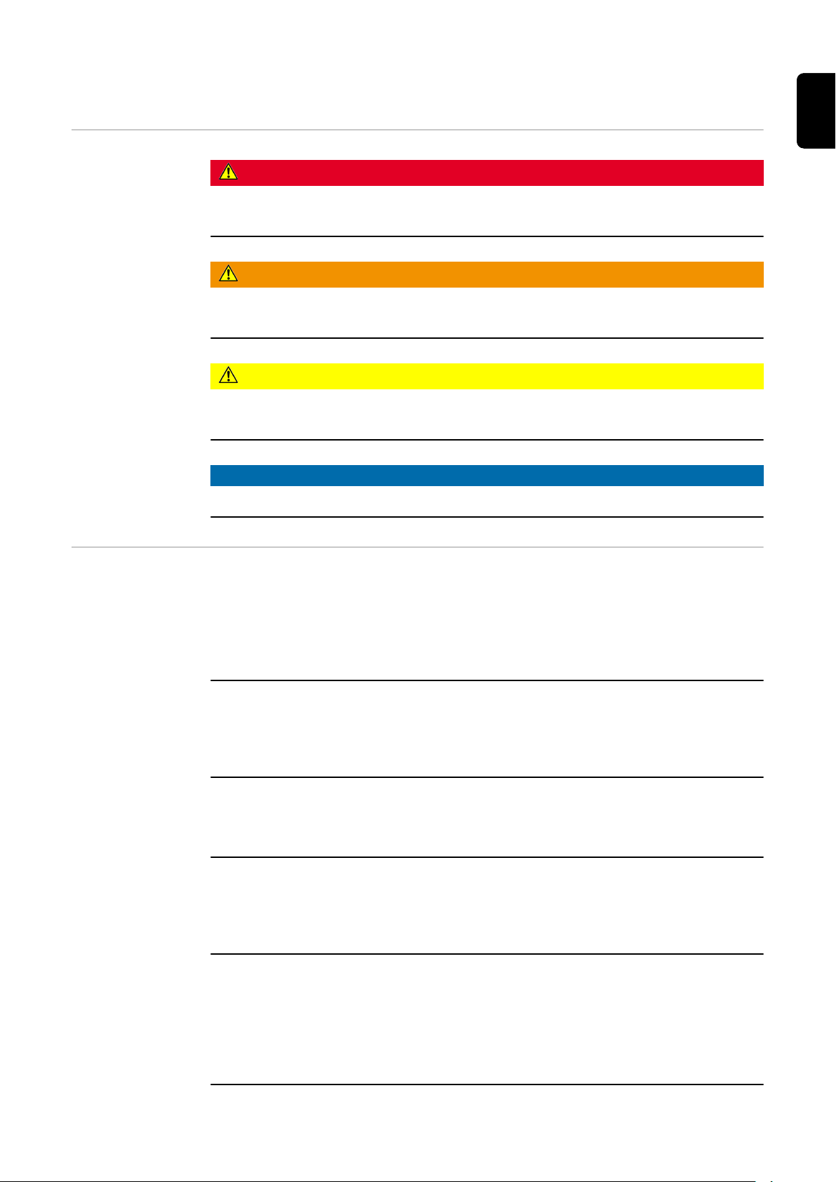
DANGER!
Indicates immediate danger.
If not avoided, death or serious injury will result.
▶
WARNING!
Indicates a potentially hazardous situation.
If not avoided, death or serious injury may result.
▶
CAUTION!
Indicates a situation where damage or injury could occur.
If not avoided, minor injury and/or damage to property may result.
▶
NOTE!
Indicates a risk of flawed results and possible damage to the equipment.
General The device has been manufactured in line with the state of the art and according
to recognized safety standards. If used incorrectly or misused, however, it can
cause:
Injury or death to the operator or a third party
-
Damage to the device and other material assets belonging to the operating
-
company.
All personnel involved in commissioning, maintenance, and servicing of the
device must:
Be suitably qualified
-
Have knowledge of and experience in dealing with electrical installations and
-
Have fully read and precisely followed these Operating Instructions
-
The Operating Instructions must always be at hand wherever the device is being
used. In addition to the Operating Instructions, attention must also be paid to
any generally applicable and local regulations regarding accident prevention and
environmental protection.
All safety and danger notices on the device:
Must be kept in a legible state
-
Must not be damaged
-
Must not be removed
-
Must not be covered, pasted or painted over
-
The terminals can reach high temperatures.
Only operate the device when all protection devices are fully functional. If the
protection devices are not fully functional, there is a danger of:
Injury or death to the operator or a third party
-
Damage to the device and other material assets belonging to the operating
-
company
7
Page 8

Any safety devices that are not fully functional must be repaired by an authorised specialist before the device is switched on.
Never bypass or disable protection devices.
For the location of the safety and danger notices on the device, refer to the section headed "General remarks" in the Operating Instructions for the device.
Any equipment malfunctions which might impair safety must be remedied before
the device is turned on.
This is for your personal safety!
Environmental
conditions
Qualified personnel
Operation or storage of the device outside the stipulated area will be deemed as
not in accordance with the intended purpose. The manufacturer accepts no liability for any damage resulting from improper use.
The servicing information contained in these operating instructions is intended
only for the use of qualified service engineers. An electric shock can be fatal. Do
not carry out any actions other than those described in the documentation. This
also applies to qualified personnel.
All cables and leads must be secured, undamaged, insulated and adequately dimensioned. Loose connections, scorched, damaged or inadequately dimensioned
cables and leads must be immediately repaired by authorised personnel.
Maintenance and repair work must only be carried out by an authorised specialist.
It is impossible to guarantee that bought-in parts are designed and manufactured to meet the demands made on them, or that they satisfy safety requirements. Use only original spare parts (also applies to standard parts).
Do not carry out any alterations, installations, or modifications to the device
without first obtaining the manufacturer's permission.
Components that are not in perfect condition must be changed immediately.
Copyright Copyright of these operating instructions remains with the manufacturer.
The text and illustrations are all technically correct at the time of printing. We
reserve the right to make changes. The contents of the operating instructions
shall not provide the basis for any claims whatsoever on the part of the purchaser. If you have any suggestions for improvement, or can point out any mistakes that you have found in the instructions, we will be most grateful for your
comments.
Data protection The user is responsible for the safekeeping of any changes made to the factory
settings. The manufacturer accepts no liability for any deleted personal settings.
8
Page 9

General information
9
Page 10

10
Page 11

Fronius Smart Meter TS 5kA-3
EN
Device description
The Fronius Smart Meter TS is a bidirectional electricity meter which optimises
self-consumption and records the household's load curve. In conjunction with
the Fronius inverter, Fronius Datamanager and Fronius data interface, the Fronius Smart Meter TS provides a clear overview of a user's own power consumption.
The meter measures the power flow to the loads or to the grid and forwards the
information via the Modbus RTU/RS485 communication to the Fronius inverter
and the Fronius Datamanager.
CAUTION!
Observe and follow safety instructions!
Failure to observe the safety instructions will result in damage to personnel and
equipment.
Switch off the power supply before establishing a mains connection.
▶
Observe the safety instructions.
▶
11
Page 12

Information on
the device
Technical data, markings and safety symbols are located on the Fronius Smart
Meter TS. These must NOT be removed or painted over. They warn against incorrect operation which can lead to serious injury and damage.
Markings:
The devices comply with all the requisite and relevant standards and
guidelines that form part of the relevant EU Directive, and are therefore
permitted to display the CE mark.
Insulated (protection class II)
Regulatory Compliance Mark (RCM)
Complies with all applicable regulatory requirements in Australia and
New Zealand regarding safety and electromagnetic compatibility, as
well as specific requirements for radio equipment.
To comply with European Directive 2012/19/EU on Waste Electrical and
Electronic Equipment and its implementation as national law, electrical
equipment that has reached the end of its life must be collected separately and returned to an approved recycling facility. Any device that you
no longer require must be returned to your distributor or disposed of at
an approved collection and recycling facility in your area. Ignoring this
European Directive may have potentially adverse effects on the environment and your health!
RoHS (Restriction of Hazardous Substances)
The limited use of certain hazardous substances in electrical and electronic equipment has been complied with in accordance with EU Directive 2011/65/EU.
Safety symbols:
Danger of serious injury and property damage due to incorrect operation.
Dangerous electrical voltage.
Intended use The Fronius Smart Meter TS is a fixed piece of equipment for public grids of
TN/TT systems and records self-consumption and/or individual loads in the system. The Fronius Smart Meter TS is required for systems with a battery storage
12
Page 13

system and/or a Fronius Ohmpilot installed for communication between the individual components. The installation is carried out on an indoor DIN rail with corresponding back-up fuses, which are adapted to the cable cross-sections of the
copper conductors and to the maximum current of the meter. The Fronius Smart
Meter TS must only be operated in accordance with the specifications in the enclosed documentation and in accordance with local laws, regulations, provisions,
standards and within the limits of technical possibilities. Any use of the product
other than as described in the intended use shall be deemed to be not in accordance with the intended purpose. The available documentation forms part of the
product and must be read, observed and kept in good condition. It must also be
accessible at all times at the place of installation. The available documents do
not replace regional, state, provincial or national laws, or regulations or standards that apply to the installation, electrical safety and use of the product. Fronius International GmbH assumes no responsibility for compliance with or noncompliance with these laws or regulations in connection with the installation of
the product.
Interventions on the Fronius Smart Meter TS, e.g. modifications and alterations,
are not permitted. Unauthorised interventions will void the warranty and warranty claims and, as a rule, void the user's authority to operate the equipment.
The manufacturer shall not be liable for any damage resulting from such use.
Reasonably foreseeable misuse:
The Fronius Smart Meter TS is not suitable for the supply of life-sustaining medical devices or for the billing of subtenants.
EN
Scope of supply
Positioning The Fronius Smart Meter TS can be installed in the following positions in the sys-
tem:
Positioning at the feed-in point:
(1) 2x seal wire
(2) 2x connection cover
(3) Fronius Smart Meter TS 5kA-3
(4) Quick Start guide
13
Page 14

Positioning at consumption point:
For use as a secondary meter to measure individual loads and producers, see
chapter Multi-meter system - Fronius SnapINverter on page 27.
Measuring accuracy
14
The Fronius Smart Meter TS has accuracy class 1 when measuring active energy
(EN IEC 62053-21) in the voltage ranges 400 - 480 VLL or 230 -277 VLN. Within
the voltage ranges 173 - 400 VLL or 100 - 230 VLN the accuracy class is 2 (active
energy according to EN IEC 62053-21, reactive energy according to EN IEC
62053-23). For further details see Technical data on page 44.
Page 15

Installation
15
Page 16

16
Page 17

Installation
EN
Checklist for installation
For installation information, see the following chapters:
Switch off the power supply before establishing a mains connection.
1
Mount the Fronius Smart Meter TS (see Installation on page 18).
2
Connect automatic circuit breakers or automatic circuit breakers and discon-
3
nectors (see Protective circuit on page 18).
Connect the mains cable to the Fronius Smart Meter TS (see Cabling on
4
page 19).
Mount the current transformers on the conductors. Make sure that the cur-
5
rent transformers are pointing in the correct direction. An arrow either points
to the load or the source (public grid) (see Connecting the current trans-
formers on page 22).
Connect the current transformer and Fronius Smart Meter TS (see Connect-
6
ing the current transformers on page 22).
Make sure that the current transformer phases match the mains voltage
7
phases (see Connecting the current transformers on page 22).
Note down the nominal current of the current transformer for each meter.
8
These values will be required during setup.
Connect the data communication connections of the Fronius Smart Meter
9
TS to the Fronius system monitoring (see Connecting the data communica-
tion cable to the inverter on page 23).
If necessary, set terminating resistors (see Connecting the terminating res-
10
istor on page 24).
Tug on each wire and plug to make sure that they are securely connected to
11
the terminal blocks.
Switch on the power supply to the Fronius Smart Meter TS.
12
Check the firmware version of the Fronius system monitoring. To ensure
13
compatibility between the inverter and the Fronius Smart Meter TS, the software must always be kept up to date. The update can be started via the inverter web page or using Solar.web.
Set the transformation ratio of the current and voltage transformers (see
14
Setting the transformation ratio of the current and voltage transformers on
page 34).
If several Fronius Smart Meter TS are installed in the system, set the address
15
(see "Setting the address" under Setting the address on the Fronius Smart
Meter TS on page 35).
Configure and commission the meter (see Start-up on page 37).
16
17
Page 18
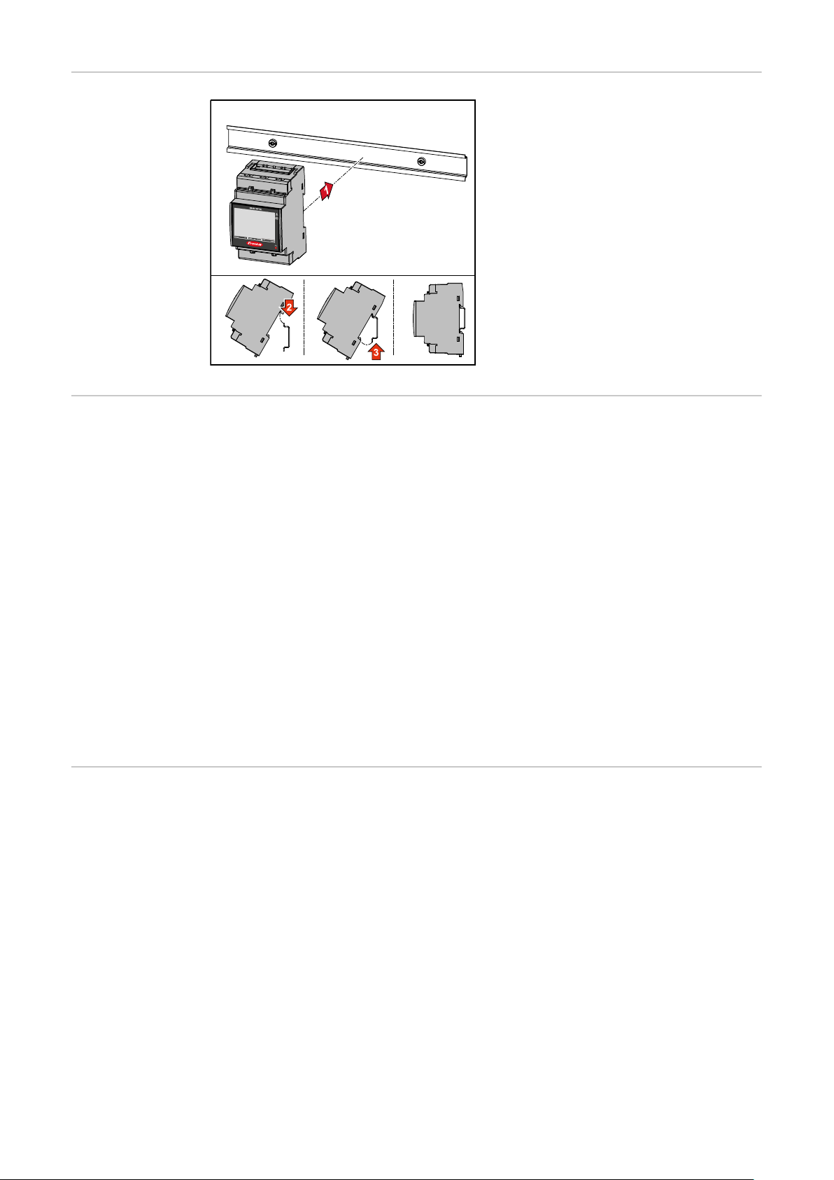
Installation The Fronius Smart Meter TS can be
mounted on a 35 mm DIN rail. The
housing comprises 3 modules according to DIN 43880.
Protective circuit
Auxiliary power
supply cabling
The Fronius Smart Meter TS is a hard-wired device and requires a disconnecting
device (circuit breaker, switch or disconnector) and overcurrent‑protection (automatic‑circuit breaker).
The Fronius Smart Meter TS consumes 10 - 30 mA, the nominal capacity of the
disconnecting devices and the overcurrent‑protection is determined by the wire
thickness, the mains voltage and the required breaking capacity.
Disconnecting devices must be mounted within sight and as close as possible
-
to the Fronius Smart Meter TS; they must also be easy to use.
The disconnecting devices must satisfy the requirements of IEC 60947-1
-
and IEC 60947-3, as well as all national and local regulations for electrical
systems.
To monitor more than one mains voltage, use connected‑automatic circuit
-
breakers.
The overcurrent‑protection must protect the mains terminals with the desig-
-
nations L1, L2 and L3. In rare cases, the neutral conductor has an overcurrent‑protection, which must interrupt both neutral and non-earthed cables
concurrently.
IMPORTANT!
An auxiliary power supply is required to operate the Fronius Smart Meter TS. The
fuse (F) must comply with the national standards and guidelines as well as the
dimensions of the conductors.
18
Page 19

Cabling IMPORTANT!
Always switch off the power supply before connecting the mains voltage inputs
to the Fronius Smart Meter TS.
Recommended thickness of stranded mains voltage cables for the terminals of
the measuring input and measuring output:
Wire: 1 - 4 mm²
-
Recommended torque: max. 0.6 Nm
-
EN
The measuring inputs of the current transformers must be earthed on one side
as shown in the circuit diagram.
Connect each voltage cable to the terminal strip as shown in the graphics below.
1 phase, 2 conductors (CT connection)
1 phase, 2 conductors (VT/CT connection)
19
Page 20

2 phases, 3 conductors (CT connection)
2 phases, 3 conductors (VT/CT connection)
20
3 phases, 3 conductors (CT connection)
3 phases, 3 conductors (VT/CT connection)
Page 21

3 phases, 4 conductors (Aron CT connection)
3 phases, 4 conductors (CT connection)
EN
Selection criteria for current
transformer
3 phases, 4 conductors (VT/CT connection)
General
Do not use current transformers with a voltage output.
Current transformers are directional. If they are mounted backwards or with
swapped wires, the measured power will be negative.
Primary current
Maximum current per phase. A current converter with a primary current greater
than the maximum expected current per phase should be selected. The closer
the expected current is to this value, the more precise the measurement will be.
Secondary current
The current transformer must supply alternating current at a nominal current of
1 or 5 A. The nominal values for the current transformer are listed in the current
transformer data sheet.
Power
The Fronius Smart Meter TS needs 0.5 VA to carry out its measurements. Losses
also occur on the outgoing and return leads. The power of the current converter
21
Page 22

must be greater than the sum total of the power of the Fronius Smart Meter TS
and the leads. The higher the power, the better.
Line resistances at different cross-sections (copper wires)
Secondary cur-
rent
[A]
Cross-section
[mm²]
Line resistances at different lead lengths
(outgoing and return lead)
0.5 m 1.0 m 2.5 m 5 m 10 m
5 1.5 0.3 VA 0.6 VA 1.5 VA 2.9 VA 5.8 VA
5 2.5 0.2 VA 0.4VA0.9 VA 1.8 VA 3.6 VA
5 4 - - 0.6 VA 1.1 VA 2.2 VA
Example
The length of the outgoing and return lead (0.5 m each) between the Fronius
Smart Meter TS and the current transformer is a total of 1 m and has a copper
cable cross-section of 1.5 mm²; the line resistance is therefore 0.6 VA according
to the table above. The self-consumption of the Fronius Smart Meter TS is 0.5
VA.
Line resistance 0.6 VA + self-consumption 0.5 VA = 1.1 VA
→ A current transformer with a rating of 1.5 VA, 5 VA or higher is suitable here.
Accuracy class
Use Class 1 or better (Class 0.5 / 0.2, etc.). Class 1 is equivalent to a deviation of
± 1% of the secondary current at maximum power.
Mounting
Rigid or hinged
"Rigid" is usually cheaper with better power and accuracy values. Hinged current
transformers can be opened for attachment to the conductor. To prevent it being
opened inadvertently, a plastic cable tie can be secured to the current transformer. Hinged current transformers can be installed in a system without interrupting the voltage.
Connecting the
current transformers
Suitable voltage
transformers
Make sure that the current transformers match the voltage phases. Make
1
sure that current transformer L1 measures the current on the same phase
that is monitored by voltage input L1. The same applies for phases L2 and L3.
Make sure that the current transformers are pointing in the correct direction.
2
Observe the data sheet for the current transformer.
Note down the nominal current of the current transformer for each meter.
3
These values will be required for setup.
Attach the current transformers to the conductor to be measured and con-
4
nect the cables of the current transformer to the Fronius Smart Meter TS.
IMPORTANT!
Always switch off the power supply before disconnecting live conductors.
The current transformers are connected to connections 4 and 5; 6 and 7; 8
5
and 9. If necessary, excessively long cables can be shortened accordingly.
Observe the sequence in which the phases are connected. Accurate power
measurement is only ensured if the mains voltage phases match the current
phases.
Only voltage transformers with a voltage range from 220 to 480 V (phase phase) and from 100 to 277 V (phase - neutral conductor) may be used. The
22
Page 23

voltage transformers must be connected to terminals 1, 2, 3 and N at the point of
direct voltage measurement.
EN
Connecting the
data communication cable to
the inverter
Connect the data communication connections of the Fronius Smart Meter TS to
the Modbus interface of the Fronius inverter using a network cable (type CAT5
or higher).
Several Smart Meters can be installed in the system, see chapter Multi-meter
system - Fronius SnapINverter on page 27.
To avoid interference, the terminating
resistor must be used (see chapter
Connecting the terminating resistor
on page 24).
Terminating resistors - Explanation of symbols
IMPORTANT!
More information on successful commissioning.
Note the following information about connecting the data communication cable
to the inverter.
Use network cables of type CAT5 or higher.
-
Use a mutual twisted cable pair for corresponding data lines (D+/D-, M1+/
-
M1-).
If the data lines are close to the mains cabling, use wires or cables that are
-
designed for 300 to 600 V (never less than the operating voltage).
Use double-insulated or sheathed data lines when they are close to bare con-
-
ductors.
Use shielded twisted pair cables to avoid faults.
-
Two wires can be installed in each terminal; the wires are twisted first, inser-
-
ted into the terminal and tightened.
Note: A loose wire can disable an entire area of the network.
The data communication connections of the Fronius Smart Meter TS are
-
electrically isolated from hazardous voltages.
Inverter in the system
e. g. Fronius Symo
Meter - Fronius Smart Meter TS
Terminating resistor R 120 Ohm is set with a wire jumper between
M- and T.
23
Page 24

Modbus RTU slave
e. g. Fronius Ohmpilot, Fronius Solar Battery, etc.
Terminating resistor
R 120 Ohm
Connecting the
terminating resistor
Terminating resistors
The terminating resistor is integrated
in the Fronius Smart Meter TS and is
manufactured with a bridge between
the M and T connections (T = termination).
Due to interference, it is recommended that terminating resistors are used as illustrated below to ensure proper functioning.
24
Page 25

EN
* The terminating resistor is integrated in the Fronius Smart Meter TS and is
manufactured with a bridge between the M and T connections (T = termination).
25
Page 26
Mounting the
connection cover
1
Insert the connection covers into the
guides and press firmly.
IMPORTANT!
When fitting the connection covers,
ensure that the cables are not kinked,
pinched, crushed or otherwise damaged.
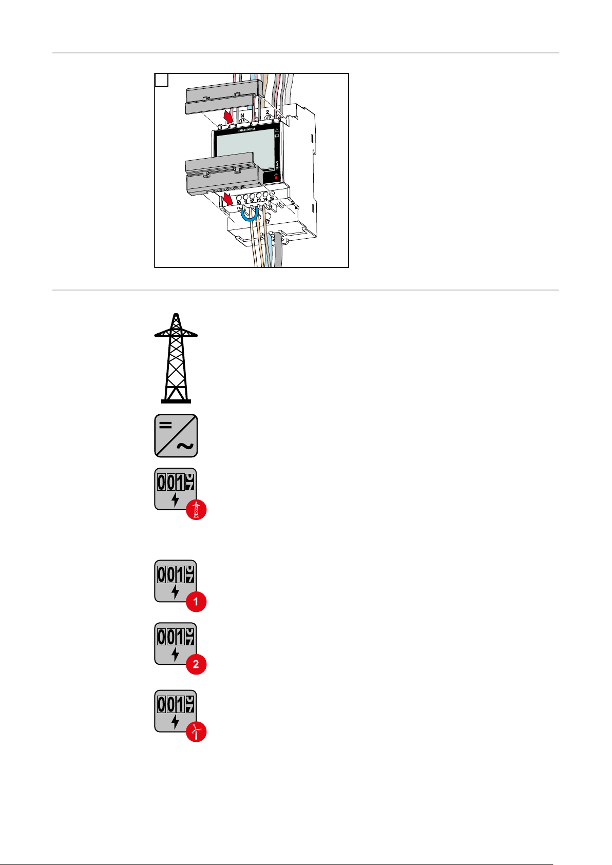
Multi-meter system - Explanation of symbols
Grid
supplies the loads in the system if insufficient power is being generated by the PV modules or supplied by the battery.
Inverter in the system
e. g. Fronius Primo, Fronius Symo, etc.
Utility meter
Measures the measurement data relevant for billing amounts of
energy (in particular kilowatt hours of energy sourced from the
grid and energy fed into the grid). Based on the relevant billing
data, the electricity retailer will invoice the energy sourced from
the grid and the purchaser of the surplus energy will reimburse
the energy fed into the grid.
Primary meter
Records the system's load curve and provides measurement data
for energy profiling in Fronius Solar.web. The primary meter also
controls the dynamic feed-in control.
26
Secondary meter
Records the load curve of individual loads (e.g. washing machine,
lamps, TV, heat pump, etc.) in the consumption branch and
provides measurement data for energy profiling in Fronius Solar.web.
Producer meter
Records the load curve of individual producers (e.g. wind power
plant) in the consumption branch and provides measurement data
for energy profiling in Fronius Solar.web.
Page 27
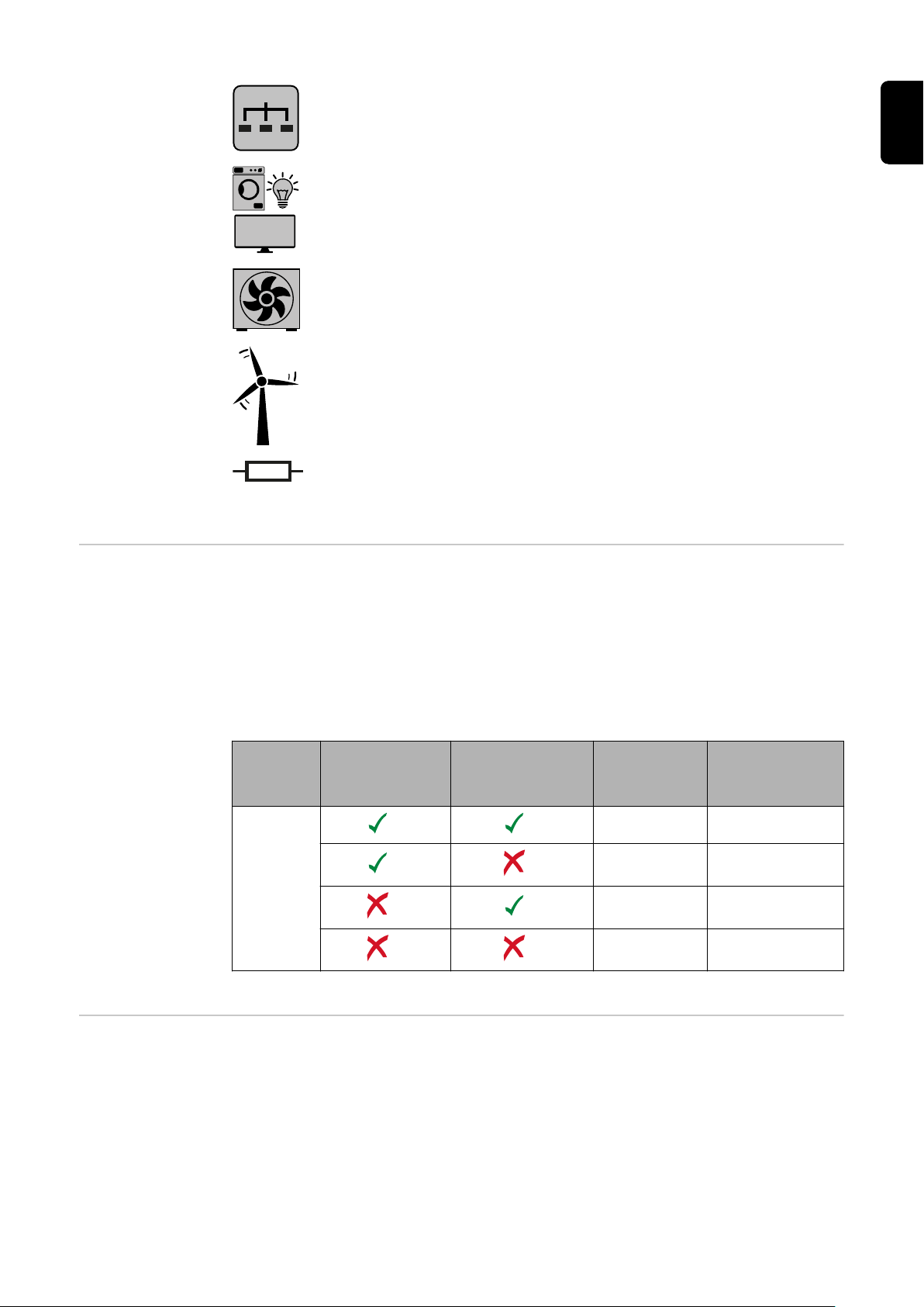
Modbus RTU slave
e. g. Fronius Ohmpilot, Fronius Solar Battery, etc.
Loads in the system
e. g. washing machine, lamps, TV, etc.
Additional loads in the system
e. g. heat pump
Additional producers in the system
e. g. wind power plant
Terminating resistor
R 120 Ohm
EN
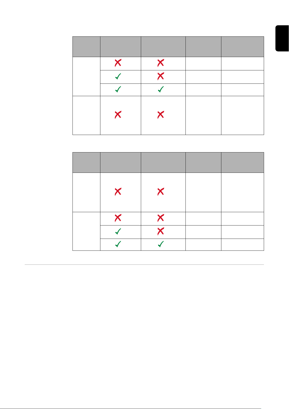
Modbus participants - Fronius
SnapInverter
A maximum of 4 Modbus participants can be connected to the Modbus terminal.
IMPORTANT!
Only one primary meter, one battery and one Ohmpilot can be connected per inverter. Due to the high data transfer of the battery, the battery occupies 2 participants.
Example:
Input Battery
Modbus
Fronius
Ohmpilot
Quantity
Primary
meter
1 0
1 1
1 2
1 3
Quantity
Secondary
meter
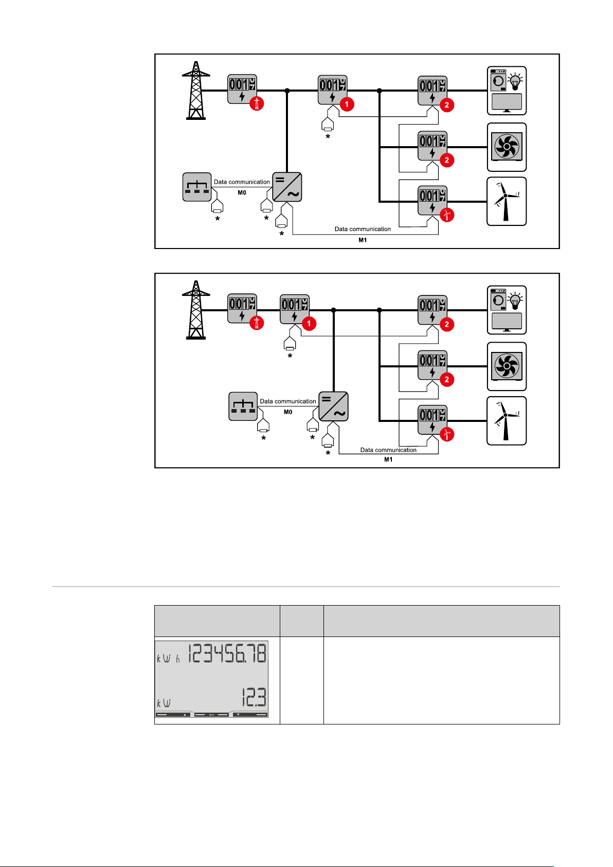
Multi-meter system - Fronius
SnapINverter
If several Fronius Smart Meter TS are installed, a separate address must be set
for each (see Setting the address on the Fronius Smart Meter TS on page 35).
The primary meter is always assigned address 1. All the other meters are
numbered consecutively with the address range from 2 to 14. Different Fronius
Smart Meter power categories can be used in combination.
IMPORTANT!
Max. Use 3 secondary meters in the system. To avoid interference, it is recom-
27
Page 28

mended to install the terminating resistors according to chapter Connecting the
terminating resistor on page 24.
Location of the primary meter in the consumption branch. *Terminating resistor R 120 Ohm
Modbus participants - Fronius
GEN24
Location of the primary meter at the feed-in point. *Terminating resistor R 120 Ohm
The following must be observed in a multi-meter system:
Only assign each Modbus address once.
-
Terminating resistors must be positioned individually for each channel.
-
The inputs M0 and M1 can be selected for this purpose. A maximum of 4 Modbus
participants can be connected to the Modbus terminal on inputs M0 and M1.
IMPORTANT!
Only one primary meter, one battery and one Ohmpilot can be connected per inverter. Due to the high data transfer of the battery, the battery occupies 2 participants.
28
Page 29
Example 1:
Input Battery
Modbus 0 (M0)
Modbus 1 (M1)
Example 2:
Input Battery
Fronius
Ohmpilot
Fronius
Ohmpilot
Quantity
Primary
meter
0 4
0 2
0 1
1 3
Quantity
Primary
meter
Quantity
Secondary
meter
Quantity
Secondary
meter
EN
Multi-meter system - Fronius
GEN24 inverter
1 3
Modbus 0 (M0)
0 4
0 2
Modbus 1 (M1)
If several Fronius Smart Meter TS are installed, a separate address must be set
for each (see Setting the address on the Fronius Smart Meter TS on page 35).
The primary meter is always assigned address 1. All the other meters are
numbered consecutively with the address range from 2 to 14. Different Fronius
Smart Meter power categories can be used in combination.
IMPORTANT!
Max. Use 7 secondary meters in the system. To avoid interference, it is recommended to install the terminating resistors according to chapter Connecting the
terminating resistor on page 24.
0 1
29
Page 30
Location of the primary meter in the consumption branch. *Terminating resistor R 120 Ohm
Location of the primary meter at the feed-in point. *Terminating resistor R 120 Ohm
The following must be observed in a multi-meter system:
Connect the primary meter and the battery to different channels (recom-
-
mended).
The remaining Modbus participants must be distributed equally.
-
Only assign each Modbus address once.
-
Terminating resistors must be positioned individually for each channel.
-
Menu - Measured
variables
30
Image ScreenDescription
00
Total active energy drawn*
1.
Total efficiency
2.
Page 31
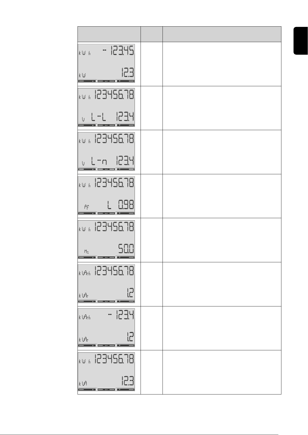
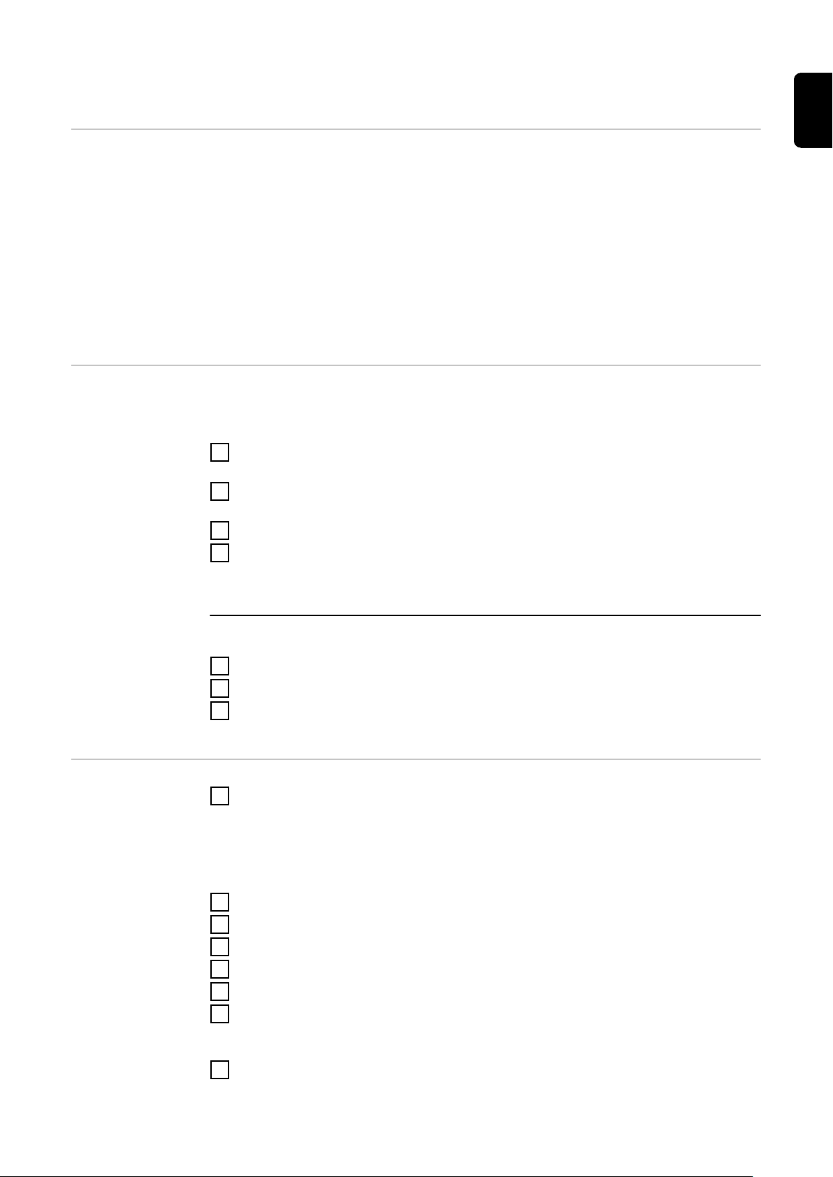
Image ScreenDescription
01
02
03
04
Total active energy supplied**
1.
Total efficiency
2.
Total active energy drawn*
1.
Average conductor voltage in the system
2.
Total active energy drawn*
1.
Average phase voltage in the system
2.
Total active energy drawn*
1.
Power factor (L = inductive, C = capacit-
2.
ive)
EN
05
06
07
08
Total active energy drawn*
1.
Frequency
2.
Total active energy drawn*
1.
Total reactive power
2.
Total reactive energy supplied**
1.
Total reactive power
2.
Total active energy drawn**
1.
Total apparent power
2.
31
Page 32

Image ScreenDescription
09
10
11
12
Total active energy drawn*
1.
Average demanded power (P = demand),
2.
calculated for the set interval. The value
remains unchanged for the entire interval. It is "0" in the first interval after the
start.
Maximum demanded power (dMd = Peak
3.
demand) that has been reached since
the last reset.
Not used
-
Not used
-
Active energy drawn*
1.
13
14
15
Apparent power
1.
Reactive energy drawn
1.
Power factor (L = inductive, C = capacit-
1.
ive)
32
Page 33

Image ScreenDescription
16
18
19
20
Phase voltage
1.
Operating hours counter
1.
Neutral current
2.
Current
1.
Effective power
1.
EN
Configuration
menu - structure
and parameters
* Displayed when easy connection mode is activated (measurement = A).
This value indicates the total energy without considering the direction.
** Factory setting - displayed when drawn and delivered energy are meas-
ured separately (measurement = b).
Screen Code Description Values
PASS*** P1 Enter the current password 2633*
nPASS P2 Password change ** Four digits (0000-9999)
SYStEM P3 Type of system 3Pn*: three-phase system,
4-core
3P: three-phase system, 3core
2P: two-phase system, 3core
Ct rAtIo P4 Current transformer ratio from 1* to 1000
Ut rAtIo P5 Voltage transformer ratio from 1* to 1000
MEASurE P6 Measurement mode ** A: easy connection, meas-
ures all energy without taking the direction into account.
B*: measures imported and
exported energy separately.
33
Page 34

Screen Code Description Values
InStALL P7 Connection check On: activated
Off*: deactivated
P int P8 Average power calculation
interval (minutes)
MOdE P9 Display mode ** Full*: full display
tArIFF P10 Tariff management ** On: activated
HoME P11 Screen showing measured
variables displayed at startup and after 120 seconds
of inactivity **
AddrESS***
bAUd P15 Baud rate (kBit/s) ** 9.6* / 19.2 / 38.4 / 57.6 /
PArITY P16 Parity ** Even/No*
STOP bit P16-2Only if parity = No. Stop bit.**1* / 2
rESET P17 Activation of the reset func-
P14 Modbus address 1* - 247
tion for energy tariffs, maximum requested power and
part values of active and reactive energy (the latter are
only transmitted via the
serial interface) **
1* - 30
Easy: reduced display. The
values that are not displayed are still transmitted
via the serial interface.
Off*: deactivated
For full display (Mode =
Full): 0* - 19
115.2
No*: reset function deactivated.
Yes: reset function activated.
Setting the
transformation
ratio of the current and voltage
transformers
End P18 Returns to the measured
variables start screen
* Factory settings
** The settings can be protected by changing the default password (pass-
word cannot be reset).
*** Settings that need to be configured.
Only the transformation ratio of the current and voltage transformers must be
set. All other parameters are preset at the factory.
Symbol Name Event Function
Up
Down
Enter
1 x
1 x
2 seconds
Scroll one screen forward, increase the
value by 1
Scroll one screen back, decrease the value
by 1
Call up settings, confirm value
None
34
Page 35

Press and hold "Enter" for 2
1
seconds.
Use "Up" or "Down" to access the
2
P1 screen.
Set password "2633" with "Up" and
3
"Down" and confirm each individual
value with "Enter".
Note down the password.
4
IMPORTANT!
The password cannot be reset.
Use "Up" or "Down" to access the
1
P4 screen.
Press and hold "Enter" for 2
2
seconds.
Set the transformation ratio with
3
"Up" and "Down" and confirm each
individual value with "Enter".
Press "Up" to access screen P18
4
and press and hold "Enter" for 2
seconds to exit the settings.
EN
Setting the address on the
Fronius Smart
Meter TS
Ratio of current transformers1) (0001 - 10002)).
Ratio of voltage transformers
1)
Important! Changing the transformation ratios will reset the counters in the
1), 3)
(001.0 - 10002)).
Fronius Smart Meter TS to 0.
2)
Transformation ratio in the current transformer x Transformation ratio of the
voltage transformers = max. 1000
3)
Changeover only when using voltage transformers (direct voltage measurement
VT = 1)
Symbol Name Event Function
Up
1 x
Scroll one screen forward, increase the
value by 1
Down
1 x
Scroll one screen back, decrease the value
by 1
Enter
2 seconds
Call up settings, confirm value
35
Page 36

Press and hold "Enter" for 2
1
seconds.
Use "Up" or "Down" to access the
2
P1 screen.
Set password "2633" with "Up" and
3
"Down" and confirm each individual
value with "Enter".
Use "Up" or "Down" to access the
1
P14 screen.
Press and hold "Enter" for 2
2
seconds.
Set the address with "Up" and
3
"Down" and confirm each individual
value with "Enter".
Press "Up" to access screen P18
4
and press and hold "Enter" for 2
seconds to exit the settings.
36
Page 37

Start-up
37
Page 38

38
Page 39
Fronius SnapINverter
General IMPORTANT! Settings under the "Meter" menu item are only to be made by
trained and qualified personnel!
The service password must be entered in order to access the "Meter" menu item.
Three-phase or single-phase Fronius Smart Meter TS can be used. In both cases,
the selection is made under the "Fronius Smart Meter" item. The Fronius
Datamanager automatically identifies the meter type.
A primary meter and several secondary meters can be selected. The primary
meter needs to be configured first before a secondary meter can be selected.
EN
Connecting to
the Fronius
Datamanager
Configuring the
Fronius Smart
Meter TS as the
primary meter
Access point:
Select the "Setup" menu on the inverter display and enable the "Wi-Fi Access
1
Point".
Establish the connection to the inverter in the network settings (the inverter
2
is displayed with the name "Fronius_240.XXXXXX").
Password: Enter 12345678 and confirm.
3
In the browser address bar, enter and confirm the IP address http://
4
192.168.250.181 and confirm.
The Fronius Datamanager start page is displayed.
LAN:
Connect the Fronius Datamanager and computer to a LAN cable.
1
Place the Fronius Datamanager IP switch in the 'A' position.
2
In the browser address bar, enter and confirm the IP address http://
3
169.254.0.180 and confirm.
Go to the Fronius Datamanager website.
1
Open the web browser.
-
In the address bar of the browser, enter the IP address (IP address for
-
WLAN: 192.168.250.181, IP address for LAN: 169.254.0.180) or the host
and domain name of the Fronius Datamanager and confirm.
The Fronius Datamanager website will be displayed.
-
Click the "Settings" button.
2
Log in to the login area with the "service" user and the service password.
3
Call up the "Meter" menu area.
4
Select the primary meter from the drop-down list.
5
Click the "Settings" button.
6
In the pop-up window, set the position of the meter (feed-in point or con-
7
sumption point). For more information on the position of the Fronius Smart
Meter TS, see Positioning on page 13.
Click the "Ok" button when the OK status is displayed. If the Timeout status
8
is displayed, try again.
39
Page 40

9
Click the button to save the settings.
The Fronius Smart Meter TS is configured as a primary meter.
The "Current general view" menu area displays the power of the PV modules,
self-consumption, the energy fed into the grid and the battery charge (if available).
Configuring the
Fronius Smart
Meter TS as a
secondary meter
Go to the Fronius Datamanager website.
1
Open the web browser.
-
In the address bar of the browser, enter the IP address (IP address for
-
WLAN: 192.168.250.181, IP address for LAN: 169.254.0.180) or the host
and domain name of the Fronius Datamanager and confirm.
The Fronius Datamanager website will be displayed.
-
Click the "Settings" button.
2
Log in to the login area with the "service" user and the service password.
3
Call up the "Meter" menu area.
4
Select the secondary meter from the drop-down list.
5
Click the "Add" button.
6
Enter the name of the secondary meter in the "Name" input field.
7
Enter the previously assigned address in the “Modbus address” input field.
8
Add meter description.
9
10
Click the button to save the settings.
The Fronius Smart Meter TS is configured as a secondary meter.
40
Page 41

Fronius GEN24 inverter
General IMPORTANT! Settings under the "Device configuration" menu item are only to be
made by trained and qualified personnel!
The service password must be entered in order to access the "Device configuration" menu item.
Three-phase or single-phase Fronius Smart Meter TS can be used. In both cases,
the selection is made under the "Components" menu area. The meter type is determined automatically.
A primary meter and several secondary meters can be selected. The primary
meter needs to be configured first before a secondary meter can be selected.
EN
Installation using the web
browser
WLAN:
1
Open the access point by touching the sensor once → Communication LED:
flashes blue.
Establish the connection to the inverter in the network settings (the inverter
2
is displayed with the name "FRONIUS_PILOT" and the serial number of the
device).
Password: enter 12345678 and confirm.
3
IMPORTANT!
To enter the password on a Windows 10 operating system, the link "Connect
using a security key instead" must first be activated to establish a connection
with the password: 12345678.
In the browser address bar, enter and confirm the IP address
4
192.168.250.181. The installation wizard is opened.
Follow the installation wizard in the individual sections and complete the in-
5
stallation.
Add system components in Solar.web and start up the PV system.
6
The network wizard and the product setup can be carried out independently of
each other. A network connection is required for the Solar.web installation wizard.
Ethernet:
41
Page 42

Establish a connection to the inverter (LAN1) with a network cable (CAT5
1
STP or higher).
2
Open the access point by touching the sensor once → Communication LED:
flashes blue.
In the browser address bar, enter and confirm IP address 169.254.0.180. The
3
installation wizard is opened.
Follow the installation wizard in the individual sections and complete the in-
4
stallation.
Add system components in Solar.web and start up the PV system.
5
The network wizard and the product setup can be carried out independently of
each other. A network connection is required for the Solar.web installation wizard.
Configuring the
Fronius Smart
Meter TS as the
primary meter
Configuring the
Fronius Smart
Meter TS as a
secondary meter
Access the inverter website.
1
Open the web browser.
-
In the address bar of the browser, enter the IP address (IP address for
-
WLAN: 192.168.250.181, IP address for LAN: 169.254.0.180) or the host
and domain name of the inverter and confirm.
The inverter website is displayed.
-
Click the "Device configuration" button.
2
Log in to the login area with the "Technician" user and the technician pass-
3
word.
Access the "Components“ menu area.
4
Click the "Add component" button.
5
In the "Position" drop-down list, set the position of the meter (feed-in point
6
or consumption point). For more information on the position of the Fronius
Smart Meter TS, see Positioning on page 13.
Click the "Add" button.
7
Click the "Save" button to save the settings.
8
The Fronius Smart Meter TS is configured as a primary meter.
Access the inverter website.
1
Open the web browser.
-
In the address bar of the browser, enter the IP address (IP address for
-
WLAN: 192.168.250.181, IP address for LAN: 169.254.0.180) or the host
and domain name of the inverter and confirm.
The inverter website is displayed.
-
Click the "Device configuration" button.
2
Log in to the login area with the "Technician" user and the technician pass-
3
word.
Access the "Components“ menu area.
4
Click the "Add component" button.
5
In the "Position" drop-down list, select the meter type (producer/load meter).
6
Enter the previously assigned address in the “Modbus address” input field.
7
Enter the name of the meter in the "Name" input field.
8
In the "Category" drop-down list, select the category (producer or load).
9
Click the "Add" button.
10
Click the "Save" button to save the settings.
11
42
Page 43

The Fronius Smart Meter TS is configured as a secondary meter.
EN
43
Page 44

Technical data
Technical data Modbus transmission speed: 9600 baud
Parity bit:none
Software version:
Fronius Datamanager 2.0 (from version 3.16.1 onwards)
-
Fronius Symo Hybrid (from version 1.16.1 onwards)
-
Measuring input
Nominal voltage (3-phase)
Operating range (class 1)
Operating range (class 2)
Nominal voltage (1-phase)
Operating range (class 1)
Operating range (class 2)
Voltage transformer ratio (kVT) 1 - 1000
Self-consumption - voltage path
(max. voltage)
Nominal frequency
Tolerance
Nominal current, l
Maximum current, I
Starting current 10 mA
Current transformer ratio (kCT) 1 - 1000
Short-time overload
(EN IEC 62053-21, EN IEC 62053-23)
b
max
400 - 480 V
320 - 552 V
173 - 400 VLL ± (2 % RDG/accuracy)
230 - 277 V
184 - 318.55 V
100 - 230 VLN ± (1 % RDG/accuracy)
e. g. VT 20000/400V kVT = 50
for direct connection: kVT = 1
10 VA
50 - 60 Hz
45 - 65 Hz
1 A + 5 A
6 A
e. g. TC 800/5A kCT = 160
for direct connection: kCT = 1
5 l
/ 0.5 s
max
44
Self-consumption - current path (max.
current)
Maximum value kVT x kCT 1000 (CT/5A)
Current distortion factor in acc. with EN IEC 62053-21
Power factor
Operating range
(EN IEC 62053-21, EN IEC 62053-23)
Energy
Max. display As per table
Resolution As per table
LED indicator 1 pulse / 0.1 Wh
Active energy accuracy
(EN IEC 62053-21)
0.3 W per phase
active cosφ 0.5 ind - 0.8 cap,
reactive sinφ 0.5 ind - 0.5 cap
Class 1
Class 2: 100 - 230 VLN (173 - 400
VLL)
Page 45

Energy
Reactive energy accuracy
(EN IEC 62053-23)
Response time after switch-on
(EN IEC 62053-21, EN IEC 62053-23)
kCT x kVT Maximum display Resolution
1 - 9.9 9 9 9 9 9 9 . 9 9 kWh / kvarh 10 Wh / varh
10 - 99.9 9 9 9 9 9 9 9 . 9 kWh / kvarh 100 Wh /
100 - 999.9 9 9 9 9 9 9 9 9 kWh / kvarh 1 kWh / varh
≥ 1000 9 9 9 9 9 9 . 9 9 MWh / kvarh 10 kWh /
Average power
Measured variable Effective power
Calculation Average value over set period of time
Integration time 5 / 8 / 10 / 15 / 20 / 30 / 60 minutes
Output
Class 2
< 5 s
varh
varh
EN
RS485 communication
Electrically isolated from input and auxiliary voltage
Standard RS485 - 3 conductors
Transmission Serial, asynchronous
Protocol Modbus RTU
Addresses 1 - 255
Number of bits 8
Stop bit 1
Parity bit None - even - odd
Baud rate 9600, 19200, 38400 bit/s
Response time ≤ 200 ms
Insulation (EN IEC 62052-11, EN IEC 62053-21)
Installation category III
Pollution degree 2
Insulation voltage 4 kV RMS
Impulse withstand voltage
Test circuit
4 kV 1.2/60 µs
Voltage input, current input, pulse
output, communication
Test voltage
Test circuit
Test voltage
Test circuit
2.75 kV RMS. 50 Hz/1 min
Voltage input, current input, pulse
output, communication
4 kV RMS. 50 Hz/1 min
All circuits and earth
45
Page 46

Electromagnetic compatibility
Test in acc. with EN IEC 62052-11
Operating conditions
Reference temperature 25 °C (± 5 °C)
Operating range -25 to +65 °C
Temperature limit for storage and
transport
Max. power loss (for thermal dimensioning of the switch cabinet)
Housing
Housing 3 modules according to DIN 43880
Sealable housing/terminal cover
Connection Screw connection
Mounting Can be snapped onto 35 mm DIN rail
Housing material Noryl, self-extinguishing
Degree of protection (EN 60529) IP54 housing, IP20 connections
Weight 240 grams
Terminals
Measuring input
Wire min. 1 mm² / max. 4 mm²
Recommended torque max. 0.6 Nm
-30 to +80 °C
≤ 2.8 W
Fronius manufacturer's warranty
Data output and auxiliary power supply
Wire min 0.05 mm² / max. 2.5 mm²
Recommended torque max. 0.4 Nm
Detailed, country-specific warranty terms are available on the internet:
www.fronius.com/solar/warranty
To obtain the full warranty period for your newly installed Fronius inverter or
storage system, please register at: www.solarweb.com.
46
Page 47

EN
47
Page 48

-
-
 Loading...