

Page 1

Installation
Instructions
Fronius Shutdown Box
Installationsanleitung
DE
Installation Instructions
EN
42,0410,2629 004-14112022
Page 2

Page 3

Inhaltsverzeichnis
Sicherheitsvorschriften 4
Erklärung Sicherheitshinweise 4
Sicherheit 4
Allgemeines 5
Qualifiziertes Personal 6
EMV-Maßnahmen 6
Allgemeine Informationen 8
Gerätekonzept 8
Bestimmungsgemäße Verwendung 8
Produktübersicht 8
Informationen am Gerät 9
Kompatibilität mit Wechselrichtern 10
Installation 11
Symbolerklärung 11
Übersicht Gesamtsystem 11
Übersicht Montagehalterung 12
Positionierung 12
Montage 13
Sicherheit 14
PV‑Modul-Stränge anschließen 15
Einstellungen - Benutzeroberfläche des Wechselrichters 16
Länder-Setup 16
Zugangs-Code 16
Parameter mit der Fronius Solar.start App anpassen 17
Parameter mit dem Browser anpassen 17
PLC aktivieren 19
Anhang 20
Technische Daten 20
Fronius Werksgarantie 20
Entsorgung 21
DE
3
Page 4

Sicherheitsvorschriften
Erklärung Sicherheitshinweise
GEFAHR!
Bezeichnet eine unmittelbar drohende Gefahr.
Wenn sie nicht gemieden wird, sind Tod oder schwerste Verletzungen die Fol-
▶
ge.
WARNUNG!
Bezeichnet eine möglicherweise gefährliche Situation.
Wenn sie nicht gemieden wird, können Tod und schwerste Verletzungen die
▶
Folge sein.
VORSICHT!
Bezeichnet eine möglicherweise schädliche Situation.
Wenn sie nicht gemieden wird, können leichte oder geringfügige Verletzun-
▶
gen sowie Sachschäden die Folge sein.
HINWEIS!
Bezeichnet die Möglichkeit beeinträchtigter Arbeitsergebnisse und von
Schäden an der Ausrüstung.
Sicherheit
WARNUNG!
Gefahr durch Fehlbedienung und fehlerhaft durchgeführte Arbeiten.
Schwerwiegende Personen- und Sachschäden können die Folge sein.
Die Inbetriebnahme darf nur durch qualifiziertes Personal und nur im Rah-
▶
men der technischen Bestimmungen erfolgen.
Vor der Installation und Inbetriebnahme die Installationsanleitung und Be-
▶
dienungsanleitung lesen.
WARNUNG!
Gefahr durch fehlerhaft durchgeführte Arbeiten.
Schwerwiegende Sach- und Personenschäden können die Folge sein.
Vor sämtlichen Einbau-und Anschlussarbeiten dafür sorgen, dass AC- und
▶
DC-Seite vor dem Wechselrichter spannungsfrei sind.
Sicherheitsvorschriften beachten!
▶
WARNUNG!
Ein elektrischer Schlag kann tödlich sein.
Unzureichend dimensionierte elektrische Komponenten können schwerwiegende
Personen- und Sachschäden verursachen.
Alle elektrischen Anschlüsse müssen entsprechend den nationalen Richtlini-
▶
en hergestellt werden.
4
Page 5

WARNUNG!
Gefahr durch offenes oder beschädigtes Gehäuse!
Schwerwiegende Personen- und Sachschäden durch Hochspannung bzw. Brandgefahr können die Folge sein.
Das Gerät nicht verwenden, wenn das Gehäuse beschädigt oder geöffnet ist.
▶
Gerät zur Reparatur einschicken.
▶
WARNUNG!
Gefahr durch beschädigte Kabel!
Schwerwiegende Personen- und Sachschäden durch beschädigte oder frei verlegte Kabel können die Folge sein.
Das Gerät nicht verwenden, wenn die am Gerät angebrachten oder ange-
▶
steckten Kabel eine Beschädigung aufweisen.
WARNUNG!
Gefahr durch nasse oder verschmutzte Stecker!
Schwerwiegende Personen- und Sachschäden können die Folge sein.
Nasse Stecker im spannungslosen Zustand trocknen.
▶
Verschmutzte Stecker im spannungslosen Zustand reinigen.
▶
DE
HINWEIS!
Die Installation und Inbetriebnahme darf nur durch eine Elektrofachkraft
durchgeführt werden!
Anforderungen an die Qualifikation von Elektrofachkräften - Kenntnis und Beachtung der 5 Sicherheitsregeln für das Arbeiten an elektrischen Anlagen.
Freischalten.
▶
Gegen Wiedereinschalten sichern.
▶
Spannungsfreiheit feststellen.
▶
Erden und kurzschließen.
▶
Benachbarte, unter Spannung stehende Teile abdecken oder abschranken.
▶
HINWEIS!
Photovoltaik-Module die Sonnenlicht ausgesetzt sind, liefern Strom an die Fronius Shutdown Box, wenn sie angeschlossen sind.
HINWEIS!
Beim Anschließen von DC-Kabeln auf korrekte Polarität achten.
Allgemeines Diese Bedienungsanleitung zur sicheren und ordnungsgemäßen Verwendung des
Geräts befolgen. Für späteres Nachschlagen aufbewahren.
Das Gerät ist nach dem Stand der Technik und den anerkannten sicherheitstechnischen Regeln gefertigt. Dennoch droht bei Fehlbedienung oder Missbrauch Gefahr für
Leib und Leben des Bedieners oder Dritter,
-
das Gerät und andere Sachwerte des Betreibers.
-
5
Page 6

Alle Personen, die mit der Inbetriebnahme, Wartung und Instandhaltung des
Geräts zu tun haben, müssen
entsprechend qualifiziert sein,
-
Kenntnisse im Umgang mit Elektroinstallationen haben und
-
diese Bedienungsanleitung vollständig lesen und genau befolgen.
-
Ergänzend zur Bedienungsanleitung die allgemein gültigen sowie die örtlichen
Vorgaben zu Unfallverhütung und Umweltschutz beachten.
Alle Sicherheits- und Gefahrenhinweise am Gerät
in lesbarem Zustand halten,
-
nicht beschädigen,
-
nicht entfernen,
-
nicht abdecken, überkleben oder übermalen.
-
Das Gerät nur betreiben, wenn alle Anschlüsse und Schutzeinrichtungen voll
funktionstüchtig sind. Wenn die Anschlüsse und Schutzeinrichtungen nicht voll
funktionstüchtig sind, besteht Gefahr für
Leib und Leben des Bedieners oder Dritter,
-
das Gerät und andere Sachwerte des Betreibers.
-
Nicht voll funktionstüchtige Sicherheitseinrichtungen vor dem Einschalten des
Geräts von einem autorisierten Fachbetrieb instand setzen lassen.
Schutzeinrichtungen niemals umgehen oder außer Betrieb setzen.
Qualifiziertes
Personal
Die Bedeutung der Sicherheits- und Gefahrenhinweise am Gerät dem Kapitel
„Informationen am Gerät“ entnehmen.
Störungen, die die Sicherheit beeinträchtigen können, vor dem Einschalten des
Geräts beseitigen.
Es geht um Ihre Sicherheit!
Die Service-Informationen in dieser Bedienungsanleitung sind nur für qualifiziertes Fachpersonal bestimmt. Ein elektrischer Schlag kann tödlich sein. Führen Sie
keine anderen als die in der Dokumentation angeführten Tätigkeiten aus. Das gilt
auch, wenn Sie dafür qualifiziert sind.
Sämtliche Kabel und Leitungen müssen fest, unbeschädigt, isoliert und ausreichend dimensioniert sein. Lose Verbindungen, angeschmorte, beschädigte oder
unterdimensionierte Kabel und Leitungen sofort von einem autorisierten Fachbetrieb instandsetzen lassen.
Wartung und Instandsetzung dürfen nur durch einen autorisierten Fachbetrieb
erfolgen.
Bei fremdbezogenen Teilen ist nicht gewährleistet, dass diese beanspruchungsund sicherheitsgerecht konstruiert und gefertigt sind. Nur Original-Ersatzteile
verwenden (gilt auch für Normteile).
EMV-Maßnahmen
6
Ohne Genehmigung des Herstellers keine Veränderungen, Ein- oder Umbauten
am Gerät vornehmen.
Bauteile in nicht einwandfreiem Zustand sofort austauschen.
In besonderen Fällen können trotz Einhaltung der genormten Emissions-Grenzwerte Beeinflussungen für das vorgesehene Anwendungsgebiet auftreten (z. B.
wenn störempfindliche Geräte am Aufstellungsort sind, oder wenn der Aufstellungsort in der Nähe von Radio- oder Fernsehempfängern ist). In diesem Fall ist
Page 7

der Betreiber verpflichtet, angemessene Maßnahmen für die Störungsbehebung
zu ergreifen.
DE
7
Page 8

Allgemeine Informationen
- - -
STR STRPV2 PV1
++ +
Gerätekonzept Die Fronius Shutdown Box erfüllt die Anforderungen zur Abschaltung auf Modu-
lebene (Module Level Shutdown, MLSD) und die Konformität mit CISPR 11 (Industrial, scientific and medical equipment - Radio-frequency disturbance characteristics - Limits and methods of measurement).
Jede Shutdown Box, die an PV‑Modulen angeschlossen ist, dekodiert das PTO‑Signal (Permission to Operate signal) des Wechselrichters über die PLC (Power Line Communication) der DC‑Kabel. Das PTO‑Signal wird im Normalbetrieb vom
Wechselrichter kontinuierlich gesendet, um den Shutdown Boxen anzuzeigen,
dass die Stromlieferung der angeschlossenen PV‑Module über die Solarmodul‑Stränge möglich ist. Wird das PTO‑Signal nicht mehr gesendet, trennt die
Shutdown Box die Stromlieferung über die Solarmodul‑Stränge.
Bestimmungsgemäße Verwendung
Produktübersicht
Die Fronius Shutdown Box ist eine Lösung für die Schnellabschaltung von
PV‑Anlagen auf PV‑Modulebene. Jede Fronius Shutdown Box ist mit 2 PV‑Modulen verbunden. Mehrere Fronius Shutdown Boxen werden in Reihe geschaltet, um
mit einem verbundenen Wechselrichter einen Strang zu bilden.
Zur bestimmungsgemäßen Verwendung gehört auch das Beachten aller Hinweise
aus der Bedienungsanleitung.
Die folgenden Sachverhalte gelten als nicht bestimmungsgemäß:
Eine andere oder über die bestimmungsgemäße Verwendung hinausgehende
-
Benutzung.
Umbauten an der Fronius Shutdown Box, die nicht ausdrücklich von Fronius
-
empfohlen werden.
Das Einbauen von Bauteilen, die nicht ausdrücklich von Fronius empfohlen
-
oder vertrieben werden.
Für hieraus entstehende Schäden haftet der Hersteller nicht. Gewährleistungsansprüche erlöschen.
Front- und Seitenansichten der Fronius Shutdown Box
Kabel (von links nach rechts)
Minuspol Strangverkabelung: STR-
-
PV‑Modul: PV2-, PV2+
-
PV‑Modul: PV1-, PV1+
-
Pluspol Strangverkabelung: STR+
-
8
Page 9

Informationen
am Gerät
Auf der Fronius Shutdown Box befinden sich technische Daten, Kennzeichnungen und Sicherheitssymbole. Die Symbole dürfen weder entfernt noch übermalt
werden. Die Hinweise und Symbole warnen vor Fehlbedienung, die zu schwerwiegenden Personen- und Sachschäden führen können.
Kennzeichnungen:
CE-Kennzeichnung
Alle erforderlichen und einschlägigen Normen sowie Richtlinien im Rahmen der einschlägigen EU-Richtlinie werden eingehalten, sodass die
Geräte mit dem CE-Kennzeichen ausgestattet sind.
WEEE-Kennzeichnung
Gemäß Europäischer Richtlinie 2012/19/EU über Elektro- und Elektronik-Altgeräte und Umsetzung in nationales Recht, müssen verbrauchte
Elektrogeräte getrennt gesammelt und einer umweltgerechten Wiederverwertung zugeführt werden. Stellen Sie sicher, dass Sie Ihr gebrauchtes Gerät bei Ihrem Händler zurückgeben oder holen Sie Informationen
über ein lokales, autorisiertes Sammel- und Entsorgungssystem ein. Ein
Ignorieren dieser EU Direktive kann zu potentiellen Auswirkungen auf
die Umwelt und Ihre Gesundheit führen!
Schutzklasse II(Schutzisolierung)
Betriebsmittel mit Schutzklasse II haben eine verstärkte oder doppelte
Isolierung in Höhe der Bemessungs-Isolations-Spannung zwischen aktiven und berührbaren Teilen (VDE 0100 Teil 410, 412.1).
DE
Sicherheitssymbole:
Allgemeines Warnzeichen
Die durch das/die Zusatzzeichen vermittelte Gefahr beachten.
Anleitung beachten
Die beschriebenen Funktionen erst anwenden, wenn folgende Dokumente vollständig gelesen und verstanden wurden:
Diese Bedienungsanleitung, insbesondere die Sicherheitsvorschrif-
-
ten.
Sämtliche Bedienungsanleitungen der Systemkomponenten der
-
Photovoltaikanlage lesen und verstehen, insbesondere die Sicherheitsvorschriften.
Warnung vor elektrischer Spannung
Darauf achten, nicht mit elektrischer Spannung in Berührung zu kommen.
Warnung vor heißer Oberfläche
Darauf achten, nicht mit heißen Oberflächen in Berührung zu kommen.
Text der Warnhinweise:
WARNUNG!
Gefahr eines Stromschlags, Abdeckung nicht entfernen.
Keine Teile im Inneren, die vom Benutzer gewartet werden können. Die Wartung
an qualifiziertes Personal übergeben. Die Fronius Shutdown Box vor der Wartung
vom Stromnetz trennen.
Heiße Oberflächen nicht berühren, um Verbrennungen zu vermeiden.
9
Page 10

Kompatibilität
mit Wechselrichtern
Die Fronius Shutdown Box ist mit folgenden Wechselrichtern kompatibel.
Fronius Symo GEN24
-
Fronius Primo GEN24
-
Fronius Tauro*
-
Fronius Tauro Eco*
-
*Voraussetzung: Zusatzoption MLSD
10
Page 11

Installation
DE
Symbolerklärung
Übersicht Gesamtsystem
Fronius Shutdown Box
Wechselrichter (Beispiel Fronius GEN24)
PV‑Modul
Gerade Anzahl an PV-Modulen
Die Darstellung zeigt den schematischen Aufbau des Gesamtsystems. An jeder
Fronius Shutdown Box sind 2 PV‑Module angeschlossen.
11
Page 12

Unerade Anzahl an PV-Modulen
130 mm (5.12 inch)
HINWEIS!
Ungerade Anzahl an PV‑Modulen.
PV2 überbrücken.
Wird aufgrund einer ungeraden Anzahl an PV‑Modulen an einer Shutdown
▶
Box nur 1 PV‑Modul angeschlossen, muss dieses an PV1 angeschlossen werden. PV2 muss durch zusammenstecken der PV2+ und PV2- Kabel
überbrückt werden.
Übersicht Montagehalterung
Positionierung Bei der Positionierung der Fronius Shutdown Box folgende Kriterien beachten.
Die Montagelage der Fronius Shutdown Box so wählen, dass die Beschriftung der Anschlüsse nach außen zeigen.
Weitere Informationen zur Montage
siehe Montage.
12
Page 13

Bei der Errichtung der PV‑Module darauf achten, dass die Lage der Anschlussdosen zur Shutdown Box mindestens den verfügbaren Kabellängen
entspricht.
Kürzest möglichen Weg von den 2
-
Anschlussdosen zur Shutdown
Box planen.
Die Abbildung zeigt 2 mögliche
-
Positionen der Fronius Shutdown
Box in optimaler Lage zu den 2 Anschlussdosen.
HINWEIS!
Die erlaubte Kabellänge zu den Eingängen beträgt max. 30 Meter.
Die maximal erlaubte Länge der Kabel zum ersten Eingang der Fronius Shutdown
Box beträgt 30 Meter.
Kabel entsprechend bemessen.
▶
DE
Montage Die Fronius Shutdown Box kann ohne Schrauben auf den Rahmen des PV‑Moduls
aufgesteckt werden.
Die Shutdown Box mit der Beschriftung nach außen am Rahmen des PV‑Mo-
1
duls aufstecken.
13
Page 14

HINWEIS!
Die Fronius Shutdown Box auf 2 Seiten der Box mit der Beschriftung nach
außen am Rahmen des PV‑Moduls befestigen.
Eine unzureichende Befestigung kann zu Schäden am Gerät führen.
Die Shutdown Box in einer Ecke des Rahmens des PV‑Moduls positionieren
▶
und an der Längs- und Querseite des Rahmens mit der Beschriftung nach
außen aufstecken.
Alternative Befestigung mit Schrauben
HINWEIS!
Montage am Rahmen des PV‑Moduls
mit geeigneten Schrauben.
Für eine senkrechte Montage muss die
Shutdown Box mit mindestens 2 geeigneten Schrauben am Rahmen des
PV‑Moduls befestigt werden.
Min. 2 geeignete Schrauben (der
▶
Lochdurchmesser beträgt 8,5 mm)
verwenden.
Die Beschriftung muss nach außen
▶
zeigen.
Kabellängen beachten (siehe Tech-
▶
nische Daten).
Sicherheit
14
GEFAHR!
Das System kann sich wegen des Notstrom-Betriebs selbst unter Spannung setzen.
Tödliche Gefahr durch elektrischen Schlag wegen Spannung im Backup-Modus.
Eine entsprechende Auslöseeinrichtung (Schalter) für die kabelgebundene
▶
Abschaltung (Wired Shutdown, WSD) verwenden.
Details zur kabelgebundenen Abschaltung (WSD) der Bedienungsanleitung
▶
des Wechselrichters entnehmen.
Page 15
WARNUNG!
Ein elektrischer Schlag kann tödlich sein.
Gefahr durch Spannung von PV‑Modulen, die Licht ausgesetzt sind.
Sämtliche Anschluss- und Service-Tätigkeiten dürfen nur dann durchgeführt
▶
werden, wenn die Eingangs- und Ausgangsseite der Fronius Shutdown Box
spannungsfrei sind.
Der Anschluss darf nur von qualifiziertem Personal hergestellt werden.
▶
Bei Systemen mit mehr als einem Wechselrichter darauf achten, dass jeder
▶
aktive Wechselrichter gefährliche Spannung liefern kann.
Keine Klemmen oder Leitungen berühren, diese können auch im ausgeschal-
▶
tetem Zustand unter Spannung stehen.
VORSICHT!
Beschädigungsgefahr durch nicht kompatible Steckverbinder.
Nicht kompatible Steckverbinder können thermische Schäden verursachen und
in Folge zu Bränden führen.
Nur die originalen Steckverbinder (MC4) der Firma Stäubli (ehemals Multi-
▶
Contact) verwenden.
VORSICHT!
Gefahr durch Verpolung an den Anschlussklemmen.
Schwere Sachschäden können die Folge sein.
Polarität der DC-Verkabelung mit einem geeigneten Messgerät prüfen.
▶
Spannung mit einem geeigneten Messgerät prüfen.
▶
DE
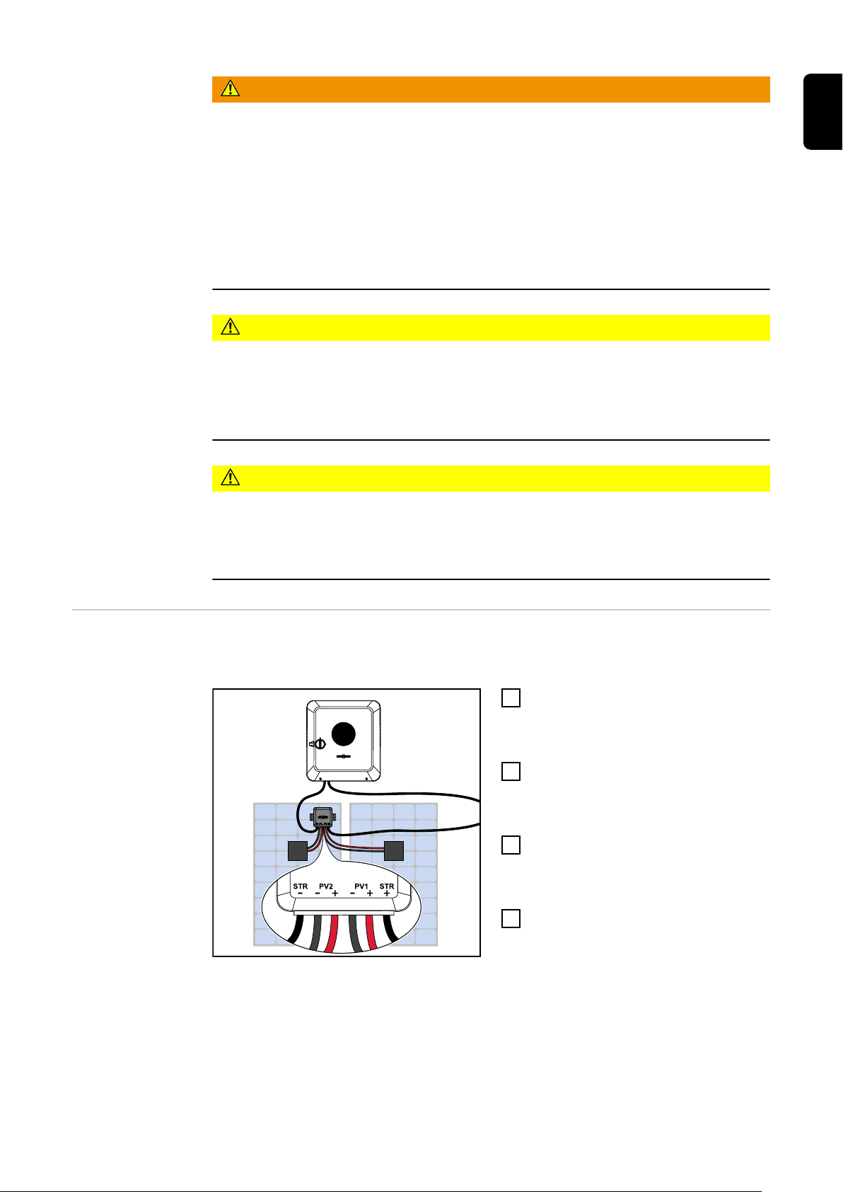
PV‑ModulStränge anschließen
Die Fronius Shutdown Box verbindet 2 PV‑Module (MC4‑Stecker) zu einem
PV‑Strang.
Den Solarmodul-Eingang PV1+
1
oder PV2+ des Wechselrichters mit
STR+ der ersten Shutdown Box
verbinden.
Die PV+ / PV- Kabel des ersten
2
PV‑Moduls in der Reihe mit den
PV2+ / PV2- Kabel der Shutdown
Box verbinden.
Die PV+ / PV- Kabel des zweiten
3
PV-Moduls in der Reihe mit den
PV1+ / PV1- Kabel der Shutdown
Box verbinden.
STR+ der Shutdown Box mit STR-
4
der nächsten Shutdown Box oder
mit dem Solarmodul-Eingang PV1oder PV2- des Wechselrichters
zum Schließen des Kreises verbinden.
Informationen zum Gesamtsystem siehe Übersicht Gesamtsystem.
15
Page 16

Einstellungen - Benutzeroberfläche des Wechsel-
richters
Länder-Setup Der Menübereich „Länder-Setup“ ist ausschließlich für Installateure/Service-
Techniker von autorisierten Fachbetrieben bestimmt. Der Zugangs-Code muss
beim nationalen/internationalen Ansprechpartner von Fronius mit einem Antragsformular beantragt werden.
VORSICHT!
Risiko durch unberechtigten Zugriff.
Falsch eingestellte Parameter können das öffentlichen Netz und/oder den NetzEinspeisebetrieb des Wechselrichters negativ beeinflussen sowie zum Verlust der
Normkonformität führen.
Die Parameter dürfen ausschließlich von Installateuren/Service-Technikern
▶
von autorisierten Fachbetrieben angepasst werden.
Den Zugangs-Code nicht an Dritte und/oder nicht autorisierte Person weiter-
▶
geben.
WARNUNG!
Gefahr durch nicht autorisierte Fehleranalysen und Instandsetzungsarbeiten.
Schwerwiegende Personen- und Sachschäden können die Folge sein.
Fehleranalysen und Instandsetzungsarbeiten an der PV-Anlage dürfen aus-
▶
schließlich von Installateuren/Service-Technikern von autorisierten Fachbetrieben gemäß den nationalen Normen und Richtlinien durchgeführt werden.
Das gewählte Länder-Setup für das jeweilige Land beinhaltet voreingestellte Parameter entsprechend der national gültigen Normen und Anforderungen.
Abhängig von örtlichen Netzverhältnissen und den Vorgaben des Netzbetreibers
können Anpassungen am ausgewählten Länder-Setup erforderlich sein.
VORSICHT!
Risiko durch falsch eingestellte Parameter.
Falsch eingestellte Parameter können das öffentlichen Netz negativ beeinflussen
und/oder Funktionsstörungen und Ausfälle am Wechselrichter verursachen sowie zum Verlust der Normkonformität führen.
Die Parameter dürfen ausschließlich von Installateuren/Service-Technikern
▶
von autorisierten Fachbetrieben angepasst werden.
Die Parameter dürfen nur angepasst werden, wenn der Netzbetreiber dies er-
▶
laubt oder fordert.
Die Parameter nur unter Berücksichtigung der national gültigen Normen
▶
und/oder Richtlinien sowie der Vorgaben des Netzbetreibers anpassen.
Zugangs-Code Der Menübereich „Länder-Setup“ ist ausschließlich für Installateure/Service-
Techniker von autorisierten Fachbetrieben bestimmt. Der Zugangs-Code muss
beim nationalen/internationalen Ansprechpartner von Fronius mit einem Antragsformular beantragt werden.
16
Page 17

VORSICHT!
1 2
open access point
Setup your PV system in a few minutes.
START INSTALLATION
LOGIN
Log in with your Fronius credentials (email adress
& password) in order to get the most out of the
PV System. Installing a new product does not
require a Login.
Imprint & Contact Terms & ConditionsData Privacy
Fronius Solar.start
open access point
1
FRONIUS_PILOTxxx
Secured
Password:
12345678
2
192.168.250.181
Parameter mit
der Fronius Solar.start App anpassen
Risiko durch unberechtigten Zugriff.
Falsch eingestellte Parameter können das öffentlichen Netz und/oder den NetzEinspeisebetrieb des Wechselrichters negativ beeinflussen sowie zum Verlust der
Normkonformität führen.
Die Parameter dürfen ausschließlich von Installateuren/Service-Technikern
▶
von autorisierten Fachbetrieben angepasst werden.
Den Zugangs-Code nicht an Dritte und/oder nicht autorisierte Person weiter-
▶
geben.
Für die Anmeldung wird die App „Fronius Solar.start“ benötigt. Abhängig vom
Endgerät ist die App auf der jeweiligen Plattform erhältlich.
DE
Parameter mit
dem Browser anpassen
Installation in der App starten.
1
Produkt auswählen, zu dem die Verbindung hergestellt werden soll.
2
3
Den Accesspoint durch Berühren des Sensors 1x öffnen → Kommunikations-LED: blinkt blau.
Im „Benutzermenü“ den Benutzer „Technician“ auswählen und das Passwort
4
für Benutzer „Technician“ eingeben und bestätigen.
Den Menübereich „Sicherheits- und Netzanforderungen“ → „Länder-Setup“
5
aufrufen.
Den angeforderten Zugangs-Code (siehe Kapitel Zugangs-Code auf Seite 16)
6
im Eingabefeld „Zugangs-Code Länder-Setup“ eingeben und die Schaltfläche
„Freischalten“ klicken.
Die Parameter in den einzelnen Menübereichen unter Berücksichtigung der
7
national gültigen Normen und/oder der Vorgaben des EnergieversorgungsUnternehmens anpassen.
WLAN:
17
Page 18

1
169.254.0.180
21
open access point
Den Access Point durch Berühren des Sensors 1x öffnen → Kommunikations-LED: blinkt blau.
Die Verbindung zum Wechselrichter in den Netzwerk-Einstellungen herstel-
2
len (der Wechselrichter wird mit dem Namen „FRONIUS_PILOT“ und der Seriennummer des Gerätes angezeigt).
Passwort: 12345678 eingeben und bestätigen.
3
WICHTIG!
Für die Passwort-Eingabe unter Windows 10 muss zuerst der Link „Verbindung stattdessen unter Verwendung eines Netzwerksicherheitsschlüssel“ aktiviert werden, um die Verbindung mit dem Passwort: 12345678 herstellen zu
können.
In der Adressleiste des Browsers die IP-Adresse 192.168.250.181 eingeben
4
und bestätigen.
Im „Benutzermenü“ den Benutzer „Technician“ auswählen und das Passwort
5
für Benutzer „Technician“ eingeben und bestätigen.
Den Menübereich „Sicherheits- und Netzanforderungen“ → „Länder-Setup“
6
aufrufen.
Den angeforderten Zugangs-Code (siehe Kapitel Zugangs-Code auf Seite 16)
7
im Eingabefeld „Zugangs-Code Länder-Setup“ eingeben und die Schaltfläche
„Freischalten“ klicken.
Die Parameter in den einzelnen Menübereichen unter Berücksichtigung der
8
national gültigen Normen und/oder der Vorgaben des Netzbetreibers anpassen.
Ethernet:
Die Verbindung zum Wechselrichter (LAN1) mit einem Netzwerk-Kabel (CA-
1
T5 STP oder höher) herstellen.
2
Den Access Point durch Berühren des Sensors 1x öffnen → Kommunikations-LED: blinkt blau.
In der Adressleiste des Browsers die IP-Adresse 169.254.0.180 eingeben und
3
bestätigen.
Im „Benutzermenü“ den Benutzer „Technician“ auswählen und das Passwort
4
für Benutzer „Technician“ eingeben und bestätigen.
Den Menübereich „Sicherheits- und Netzanforderungen“ → „Länder-Setup“
5
aufrufen.
Den angeforderten Zugangs-Code (siehe Kapitel Zugangs-Code auf Seite 16)
6
im Eingabefeld „Zugangs-Code Länder-Setup“ eingeben und die Schaltfläche
„Freischalten“ klicken.
Die Parameter in den einzelnen Menübereichen unter Berücksichtigung der
7
national gültigen Normen und/oder der Vorgaben des Netzbetreibers anpassen.
18
Page 19

PLC aktivieren Einstellungen GEN24 und Tauro Wechselrichter
Folgende Einstellungen für die Aktivierung der Power Line Communication (PLC)
der Fronius Shutdown Box mit einem Fronius GEN24 oder Fronius Tauro Wechselrichter vornehmen.
Im Menübereich „Länder-Setup Anmeldung“ mit dem Zugangs-Code (siehe
1
Kapitel Zugangs-Code auf Seite 16) das Länder-Setup freischalten.
Auf „Sicherheit“ klicken.
2
In der Drop‑Down-Auswahl am Ende der Seite unter DC Shutdown Commu-
3
nication „PLC“ auswählen.
DE
19
Page 20

Anhang
Technische Daten
Allgemeine Daten
Abmessungen (Breite x Höhe x Tiefe),
inkl. Montagehalterung
Gewicht 0,790 kg
Umgebungstemperatur -40 °C bis +85 °C
Luftfeuchtigkeit 0 bis 100 %
Seehöhe 0 m bis 2000 m
Kühlungmethode natürliche Umluft
EMV Emissionsklasse B
Schutzklasse IP 68
Verschmutzungsgrad 3
Überspannungskategorie DC 2
Kabel
Typ FLEX‑SOL‑EVO‑DX 4,0
Nominalspannung 1000 V
Kabelquerschnitt
15,1 x 11,7 x 2,4 cm
2
4 mm
AWG 12
Verbindungsstecker MC4
Kabellängen
STR- / +
-
PV1- / +
-
PV2- / +
-
Eingangsdaten je Eingang (PV1, PV2)
Eingangsspannung 8 ‑ 80 V
Eingangsstrom 0 ‑ 15 A
Max. Eingangsstrom 15 A
Max. Eingangsleistung 600 W
Ausgangsdaten
Ausgangsspannung 0 ‑ 160 V
Max. Systemspannung 1000 V
Datenkommunikation
Art PLC (Power Line Communication)
221 cm
16 cm
26 cm
Fronius Werksgarantie
20
Detaillierte, länderspezifische Garantiebedingungen sind im Internet erhältlich:
www.fronius.com/solar/garantie
Page 21

Entsorgung Elektro- und Elektronik-Altgeräte müssen gemäß Europäischer Richtlinie und na-
tionalem Recht getrennt gesammelt und einer umweltgerechten Wiederverwertung zugeführt werden. Gebrauchte Geräte sind beim Händler oder über ein lokales, autorisiertes Sammel- und Entsorgungssystem zurückzugegeben. Eine
fachgerechte Entsorgung des Altgeräts fördert eine nachhaltige Wiederverwertung von stofflichen Ressourcen. Ein Ignorieren kann zu potenziellen Auswirkungen auf die Gesundheit/Umwelt führen.
Verpackungsmaterialien
Getrennte Sammlung. Prüfen Sie die Vorschriften Ihrer Gemeinde. Verringern
Sie das Volumen des Kartons.
DE
21
Page 22

22
Page 23

Contents
Safety rules 24
Explanation of safety notices 24
Safety 24
General 25
Qualified personnel 26
EMC measures 26
General information 28
Device concept 28
Intended use 28
Product overview 28
Information on the device 29
Compatibility with inverters 29
Installation 30
Explanation of symbols 30
Overview of entire system 30
Overview of mounting bracket 31
Positioning 31
Installation 32
Safety 33
Connecting PV module strings 34
Settings - user interface of the inverter 35
Country setup 35
Access code 35
Adjusting parameters with the Fronius Solar.start app 36
Adjusting parameters with the browser 36
Activate PLC 37
Appendix 38
Technical data 38
Fronius manufacturer's warranty 38
Disposal 39
EN
23
Page 24

Safety rules
Explanation of
safety notices
DANGER!
Indicates immediate danger.
If not avoided, death or serious injury will result.
▶
WARNING!
Indicates a potentially hazardous situation.
If not avoided, death or serious injury may result.
▶
CAUTION!
Indicates a situation where damage or injury could occur.
If not avoided, minor injury and/or damage to property may result.
▶
NOTE!
Indicates a risk of flawed results and possible damage to the equipment.
Safety
WARNING!
Danger due to incorrect operation and incorrectly performed work.
This can result in serious injury and damage to property.
Only qualified personnel are authorised to perform commissioning and only
▶
within the scope of the respective technical regulations.
Read the Installation and Operating Instructions before installing and com-
▶
missioning the equipment.
WARNING!
Danger due to work that has been carried out incorrectly.
This may result in serious injury and damage to property.
Ensure that both the AC side and the DC side of the inverter are de-energi-
▶
sed before carrying out any installation and connection work.
Follow the safety rules.
▶
WARNING!
An electric shock can be fatal.
Inadequately dimensioned electrical components can cause serious injury or damage to property.
All electrical connections must be made in accordance with national guideli-
▶
nes.
24
Page 25

WARNING!
Danger due to open or damaged housing!
This can result in severe personal injury and damage to property due to high voltage and/or sparking.
Do not use the device if the housing is damaged or open.
▶
Send in the device for repair.
▶
WARNING!
Danger due to damaged cables!
Damaged or exposed cables can result in severe personal injury and damage to
property.
Do not use the device if the cables attached to or plugged into the device are
▶
damaged.
WARNING!
Danger due to wet or dirty connectors!
This can result in serious injury and damage to property.
Dry wet connectors in a de-energised state.
▶
Clean soiled connectors in a de-energised state.
▶
EN
NOTE!
Installation and commissioning may only be performed by a qualified electrician.
Requirements for the qualification of electricians - knowledge and observation of
the 5 safety rules for working on electrical systems.
Disconnect.
▶
Ensure the device cannot be switched back on.
▶
Ensure the system is no longer live.
▶
Carry out earthing and short-circuiting.
▶
Cover nearby live components or make them inaccessible.
▶
NOTE!
Photovoltaic modules that are exposed to sunlight supply current to the Fronius
Shutdown Box when they are connected.
NOTE!
Ensure the polarity is correct when connecting the DC cables.
General Follow these Operating Instructions to ensure safe and proper use of the device.
Keep for later reference.
The device has been manufactured in line with the state of the art and according
to recognised safety standards. If used incorrectly or misused, however, it can
cause:
Serious or fatal injury to the operator or third parties
-
Damage to the device and other material assets belonging to the operating
-
company
25
Page 26

All personnel involved in commissioning, maintenance and servicing of the device
must:
Be suitably qualified
-
Have knowledge of and experience in dealing with electrical installations
-
Have fully read and precisely followed these Operating Instructions
-
In addition to the Operating Instructions, all applicable local rules and regulations regarding accident prevention and environmental protection must also be
followed.
All safety and danger notices on the device:
Must be kept in a legible state
-
Must not be damaged
-
Must not be removed
-
Must not be covered, pasted or painted over
-
Only operate the device when all connections and protection devices are fully
functional. If the connections and protection devices are not fully functional,
there is a danger of
Serious or fatal injury to the operator or third parties
-
Damage to the device and other material assets belonging to the operating
-
company
Any safety devices that are not fully functional must be repaired by an authorised specialist before the device is switched on.
Qualified personnel
Never bypass or disable protection devices.
For the meaning of the safety and danger notices on the device, refer to the section headed "Information on the device".
Any equipment malfunctions which might impair safety must be remedied before
the device is turned on.
This is for your personal safety!
The servicing information contained in these operating instructions is intended
only for the use of qualified service engineers. An electric shock can be fatal. Do
not carry out any actions other than those described in the documentation. This
also applies to qualified personnel.
All cables and leads must be secured, undamaged, insulated and adequately dimensioned. Loose connections, scorched, damaged or inadequately dimensioned
cables and leads must be immediately repaired by authorised personnel.
Maintenance and repair work must only be carried out by an authorised specialist.
It is impossible to guarantee that bought-in parts are designed and manufactured to meet the demands made on them, or that they satisfy safety requirements. Use only original spare parts (also applies to standard parts).
Do not carry out any alterations, installations, or modifications to the device without first obtaining the manufacturer's permission.
Components that are not in perfect condition must be changed immediately.
EMC measures In certain cases, even though a device complies with the standard limit values for
emissions, it may affect the application area for which it was designed (e.g., when
there is equipment that is susceptible to interference at the same location, or if
26
Page 27

the site where the device is installed is close to either radio or television receivers). If this is the case, then the operator is obliged to take appropriate action to
rectify the situation.
EN
27
Page 28

General information
- - -
STR STRPV2 PV1
++ +
Device concept The Fronius Shutdown Box meets the requirements for shutdown at module level
(Module Level Shutdown, MLSD) and conformity with CISPR 11 (Industrial, scientific and medical equipment - Radio-frequency disturbance characteristics Limits and methods of measurement).
Each Shutdown Box connected to PV modules decodes the PTO signal (Permission to Operate signal) of the inverter via the PLC (Power Line Communication) of
the DC cables. The PTO signal is sent continuously by the inverter during normal
operation to indicate to the Shutdown Boxes that power can be supplied to the
connected PV modules via the solar module strings. If the PTO signal is no longer transmitted, the Shutdown Box disconnects the power supply via the solar
module strings.
Intended use The Fronius Shutdown Box is a solution for the rapid shutdown of PV systems at
PV‑module level. Each Fronius Shutdown Box is connected to two PV modules.
Several Fronius Shutdown Boxes are connected in series to form a string with a
connected inverter.
Product overview
Intended use also includes complying with all the instructions in the Operating
Instructions.
The following circumstances are considered improper:
Use other than or in excess of the intended use.
-
Making any modifications to the Fronius Shutdown Box that have not been
-
expressly approved by Fronius.
Installation of components that are not distributed or expressly approved by
-
Fronius.
The manufacturer shall not be liable for any damage resulting from such use. All
warranty claims will be forfeited.
Front and side views of the Fronius
Shutdown Box
Cables (from left to right)
Negative pole string wiring: STR-
-
PV module: PV2-, PV2+
-
PV module: PV1-, PV1+
-
Positive pole string wiring: STR+
-
28
Page 29

Information on
the device
Technical data, markings and safety symbols are affixed to the Fronius Shutdown
Box. The symbols must not be removed or painted over. They warn against incorrect operation which can lead to serious injury and damage to property.
Markings:
CE mark
The devices conform to all the requisite and relevant standards and guidelines that form part of the relevant EU directive, and are therefore
permitted to display the CE mark.
WEEE mark
To comply with European Directive 2012/19/EU on Waste Electrical and
Electronic Equipment and its implementation as national law, electrical
equipment that has reached the end of its life must be collected separately and returned to an approved recycling facility. Any device that you
no longer require must be returned to your distributor or disposed of at
an approved collection and recycling facility in your area. Ignoring this
European Directive may have potentially adverse effects on the environment and your health!
Protection class II(protective insulation)
Equipment of protection class II has a reinforced or double insulation in
the amount of the rated insulation voltage between live and touchable
parts (VDE 0100 part 410, 412.1).
Safety symbols:
EN
General warning symbol
Observe the danger conveyed by the additional symbol(s).
Heed the instructions
Do not use the functions described until you have thoroughly read and
understood the following documents:
These Operating Instructions, in particular the safety rules.
-
All Operating Instructions for the system components of the pho-
-
tovoltaic system, especially the safety rules.
Warning of electrical voltage
Take care not to come into contact with electrical voltage.
Warning of a hot surface
Take care not to come into contact with hot surfaces.
Text of the warning notices:
WARNING!
Danger of electric shock; do not remove cover.
No user-serviceable parts inside. Hand over maintenance to qualified personnel.
Disconnect the Fronius Shutdown Box from the grid before maintenance.
Do not touch hot surfaces to avoid burns.
Compatibility
with inverters
The Fronius Shutdown Box is compatible with the following inverters.
Fronius Symo GEN24
-
Fronius Primo GEN24
-
Fronius Tauro*
-
Fronius Tauro Eco*
-
*Requirement: Additional option MLSD
29
Page 30

Installation
Explanation of
symbols
Overview of entire system
Fronius Shutdown Box
Inverter (example Fronius GEN24)
PV module
Even number of PV modules
30
The illustration shows the schematic structure of the entire system. Two PV modules are connected to each Fronius Shutdown Box.
Page 31

Odd number of PV modules
130 mm (5.12 inch)
NOTE!
Odd number of PV modules.
Bridge PV2.
If only one PV module is connected to a Shutdown Box due to an odd num-
▶
ber of PV modules, this module must be connected to PV1. PV2 must be
bridged by connecting the PV2+ and PV2- cables together.
EN
Overview of
mounting bracket
Positioning Observe the following criteria when positioning the Fronius Shutdown Box.
Select the installation position of the
Fronius Shutdown Box so that the labelling of the connections faces outwards.
For more information on mounting, see
Installation.
31
Page 32

When installing the PV modules, ensure that the position of the junction boxes in relation to the Shutdown Box
corresponds at least to the available
cable lengths.
Plan the shortest possible path
-
from the two junction boxes to the
Shutdown Box.
The illustration shows two possible
-
positions of the Fronius Shutdown
Box in optimal position in relation
to the two junction boxes.
NOTE!
The permitted cable length to the inputs is max. 30 metres.
The maximum permitted length of the cables to the first input of the Fronius
Shutdown Box is 30 metres.
Dimension the cables accordingly.
▶
Installation The Fronius Shutdown Box can be attached to the frame of the PV module wi-
thout screws.
Attach the Shutdown Box to the frame of the PV module with the text facing
1
outwards.
32
Page 33

NOTE!
Attach the Fronius Shutdown Box to the frame of the PV module on two sides of
the box with the text facing outwards.
Inadequate fixing may result in damage to the device.
Position the Shutdown Box in one corner of the frame of the PV module and
▶
attach it to the long and short sides of the frame with the text facing outwards.
Alternative fastening with screws
NOTE!
Mounting on the frame of the PV module with suitable screws.
For vertical mounting, the Shutdown
Box must be fastened to the frame of
the PV module with at least two suitable screws.
Use min. two suitable screws (the
▶
hole diameter is 8.5 mm).
The text must face outwards.
▶
Observe cable lengths (see Tech-
▶
nical data).
EN
Safety
DANGER!
The system may energise itself due to backup power operation.
Risk of fatal electric shock due to voltage in backup mode.
Use an appropriate tripping device (switch) for the wired shut down (WSD).
▶
For details on the wired shut down (WSD), refer to the Operating Instruc-
▶
tions of the inverter.
33
Page 34

WARNING!
An electric shock can be fatal.
Danger due to voltage from PV modules that are exposed to light.
All connection and service activities may only be carried out when the input
▶
and output sides of the Fronius Shutdown Box are voltage-free.
The connection may only be established by qualified personnel.
▶
In systems with more than one inverter, be aware that each active inverter
▶
can supply dangerous voltage.
Do not touch any terminals or lines, these may be live even when switched
▶
off.
CAUTION!
Risk of damage as the result of incompatible plug connectors.
Incompatible plug connectors can cause heat damage that may result in a fire.
Only use the original plug connectors (MC4) manufactured by Stäubli (form-
▶
erly Multi-Contact).
CAUTION!
Danger due to polarity reversal at the terminals.
This can result in severe damage to property.
Use a suitable measuring instrument to check the polarity of the DC cabling.
▶
Check the voltage with a suitable measuring instrument.
▶
Connecting PV
module strings
The Fronius Shutdown Box connects two PV modules (MC4 connector) to form a
PV string.
Connect the solar module input
1
PV1+ or PV2+ of the inverter to
STR+ of the first Shutdown Box.
Connect the PV+ / PV- cables of
2
the first PV‑module in the series to
the PV2+ / PV2- cables of the
Shutdown Box.
Connect the PV+ / PV- cables of
3
the second PV module in the series
to the PV1+ / PV1- cables of the
Shutdown Box.
Connect STR+ of the Shutdown
4
Box to STR- of the next Shutdown
Box or to the solar module input
PV1- or PV2- of the inverter to close the circuit.
For information on the overall system, see Overview of entire system.
34
Page 35
Settings - user interface of the inverter
Country setup The "Country Setup" menu area is intended exclusively for installers/service
technicians from authorised specialist companies. The access code must be requested from the national/international Fronius point of contact using an application form.
CAUTION!
Risk due to unauthorised access.
Incorrectly set parameters can negatively influence the public grid and/or the inverter feeding energy into the grid, and lead to a loss of conformity with the standard.
The parameters may only be adjusted by installers/service technicians from
▶
authorised specialist companies.
Do not give the access code to third parties and/or unauthorised persons.
▶
WARNING!
Danger due to unauthorised error analyses and repair work.
This can result in serious injury and damage to property.
Fault analyses and repair work on the photovoltaic system may only be carri-
▶
ed out by installers/service technicians from authorized specialist companies
in accordance with national standards and guidelines.
EN
The selected country setup for the respective country contains preset parameters according to the nationally applicable standards and requirements. Depending on local grid conditions and the specifications of the energy provider, adjustments to the selected country setup may be necessary.
CAUTION!
Risk due to incorrectly set parameters.
Incorrectly set parameters can negatively influence the public grid and/or cause
faults and failures on the inverter, and lead to the loss of standard conformity.
The parameters may only be adjusted by installers/service technicians from
▶
authorised specialist companies.
The parameters may only be adjusted if the energy provider permits or requi-
▶
res this.
Only adjust the parameters taking into account the nationally applicable
▶
standards and/or directives and the specifications of the energy provider.
Access code The "Country setup" menu area is intended exclusively for installers/service tech-
nicians from authorised specialist companies. The access code must be requested from the national/international Fronius point of contact using an application
form.
35
Page 36

CAUTION!
1 2
open access point
Setup your PV system in a few minutes.
START INSTALLATION
LOGIN
Log in with your Fronius credentials (email adress
& password) in order to get the most out of the
PV System. Installing a new product does not
require a Login.
Imprint & Contact Terms & ConditionsData Privacy
Fronius Solar.start
open access point
1
FRONIUS_PILOTxxx
Secured
Password:
12345678
2
192.168.250.181
Risk due to unauthorised access.
Incorrectly set parameters can negatively influence the public grid and/or the inverter feeding energy into the grid, and lead to a loss of conformity with the standard.
The parameters may only be adjusted by installers/service technicians from
▶
authorised specialist companies.
Do not give the access code to third parties and/or unauthorised persons.
▶
Adjusting parameters with the
Fronius Solar.start app
The "Fronius Solar.start" app is needed for registration. Depending on the end
device, the app is available on the respective platform.
Start the installation in the app.
1
Select the product to which the connection should be established.
2
3
Open the access point by touching the sensor once → Communication LED:
flashes blue.
Select the "Technician" user in the "User menu" and enter and confirm the
4
password for the "Technician" user.
Call up the "Safety and grid regulations" → "Country setup" menu area.
5
Enter the requested access code (see chapter Access code on page 35) in
6
the input field "Access code country setup" and click the button "Activate".
Adjust the parameters in the individual menu areas taking into account the
7
nationally applicable standards and/or the specifications of the energy provider.
Adjusting parameters with the
browser
36
WLAN:
1
Open the access point by touching the sensor once → Communication LED:
flashes blue.
Page 37

Establish the connection to the inverter in the network settings (the inverter
169.254.0.180
21
open access point
2
is displayed with the name "FRONIUS_PILOT" and the serial number of the
device).
Password: enter 12345678 and confirm.
3
IMPORTANT!
To enter the password on a Windows 10 operating system, the link "Connect
using a security key instead" must first be activated to establish a connection
with the password: 12345678.
In the browser address bar, enter and confirm the IP address
4
192.168.250.181.
Select the "Technician" user in the "User menu" and enter and confirm the
5
password for the "Technician" user.
Call up the "Safety and grid regulations" → "Country setup" menu area.
6
Enter the requested access code (see chapter Access code on page 35) in
7
the input field "Access code country setup" and click the button "Activate".
Adjust the parameters in the individual menu areas taking into account the
8
nationally applicable standards and/or the specifications of the grid operator.
Ethernet:
EN
Establish a connection to the inverter (LAN1) with a network cable (CAT5
1
STP or higher).
2
Open the access point by touching the sensor once → Communication LED:
flashes blue.
In the browser address bar, enter and confirm IP address 169.254.0.180.
3
Select the "Technician" user in the "User menu" and enter and confirm the
4
password for the "Technician" user.
Call up the "Safety and grid regulations" → "Country setup" menu area.
5
Enter the requested access code (see chapter Access code on page 35) in
6
the input field "Access code country setup" and click the button "Activate".
Adjust the parameters in the individual menu areas taking into account the
7
nationally applicable standards and/or the specifications of the grid operator.
Activate PLC GEN24 and Tauro inverter settings
Make the following settings to activate the Power Line Communication (PLC) of
the Fronius Shutdown Box with a Fronius GEN24 or Fronius Tauro inverter.
Activate the country setup in the "Login Country Setup" menu area with the
1
access code (see chapter Access code on page 35).
Click on "Safety".
2
In the drop‑down list at the bottom of the page, select "PLC" under DC Shut-
3
down Communication.
37
Page 38

Appendix
Technical data
General data
Dimensions (width x height x depth),
incl. mounting bracket
Weight 0.790 kg
Ambient temperature -40 °C to +85 °C
Humidity 0 to 100 %
Height above sea level 0 m to 2000 m
Cooling method Natural air circulation
EMC emission class B
Safety class IP 68
Pollution degree 3
DC overvoltage category 2
Cables
Type FLEX‑SOL‑EVO‑DX 4.0
Nominal voltage 1000 V
Cable cross-section
15.1 x 11.7 x 2.4 cm
2
4 mm
AWG 12
Connector MC4
Cable lengths
STR- / +
-
PV1- / +
-
PV2- / +
-
Input data per input (PV1, PV2)
Input voltage 8 ‑ 80 V
Input current 0 ‑ 15 A
Max. input current 15 A
Max. input power 600 W
Output data
Output voltage 0 ‑ 160 V
Max. system voltage 1000 V
Data communication
Type PLC (Power Line Communication)
221 cm
16 cm
26 cm
Fronius manufacturer's warranty
38
Detailed, country-specific warranty conditions are available on the internet
www.fronius.com/solar/garantie
Page 39

Disposal Waste electrical and electronic equipment must be collected separately and re-
cycled in an environmentally-friendly way, in accordance with the European Directive and national legislation. Used equipment must be returned to the distributor or disposed of via an approved local collection and disposal facility. Correct disposal of used equipment promotes the sustainable recycling of material
resources. Failing to dispose of used equipment correctly can lead to adverse health and/or environmental impacts.
Packaging materials
Separate collection according to material. Check your local authority regulations.
Crush containers to reduce size.
EN
39
Page 40

-
-
 Loading...