

Page 1

Operating
Instructions
Fronius Primo
3.0-1 / 3.5-1 / 3.6-1 / 4.0-1
4.6-1 / 5.0-1 AUS / 5.0-1
5.0-1 SC / 6.0-1 / 8.2-1
Operating Instructions
EN
Instructions de service
FR
Bedieningshandleiding
NL
42,0410,2148 027-20012023
Page 2

Page 3

Contents
Safety rules 5
General 5
Environmental conditions 5
Qualified personnel 5
Noise emission values 6
EMC measures 6
Disposal 6
Data protection 6
Copyright 6
General 8
Explanation of safety notices 8
Device concept 8
Proper use/intended purpose 9
Warning notices on the device 9
Data communication and Fronius Solar Net 11
Fronius Solar Net and data interface 11
Data communication area 11
Explanation of the multifunction current interface 12
Description of the "Fronius Solar Net" LED 13
Example 14
Installing option cards in the inverter 14
Dynamic power reduction by means of inverter 15
System monitoring 16
General 16
Fronius Datamanager during the night or when the available DC voltage is insufficient 16
Starting for the first time 16
Further information on Fronius Datamanager 2.0 18
Controls and indicators 19
Controls and displays 19
Display 20
The menu level 21
Activating display backlighting 21
Automatic deactivation of display backlighting / changing to the "NOW" menu item 21
Open menu level 21
The NOW, LOG and GRAPH menu items 22
NOW LOG GRAPH 22
Values displayed in the NOW and LOG menu items 22
SETUP menu item 24
Initial setting 24
SETUP 24
Navigating the SETUP menu item 24
Setting menu entries, general 25
Application example: Setting the time 26
The Setup menu items 28
Standby 28
WiFi Access Point 28
DATCOM 29
USB 29
Relay (floating contact switch) 31
Energy Manager(under Relay menu item) 32
Time / Date 33
Display settings 34
ENERGY YIELD 35
Fan 36
The INFO menu item 37
INFO 37
Measured values PSS status Grid status 37
Device information 38
Version 39
Switching the key lock on and off 40
EN
3
Page 4

General 40
Switching the key lock on and off 40
USB Stick as a Data Logger and for Updating Inverter Software 41
USB flash drive as a datalogger 41
Suitable USB flash drives 41
USB stick for updating the inverter software 42
Removing the USB flash drive 42
The Basic menu 43
General 43
Access the Basic menu 43
Menu items in the Basic menu 43
Switching off current supply and restarting the inverter 45
Switch off power to the inverter 45
Status diagnostics and troubleshooting 46
Status code display 46
Total failure of the display 46
Status codes in the e-Manual 46
Customer service 46
Operation in dusty environments 46
Technical data 47
General data and protection devices Fronius Primo 3.0-1 - 8.2-1 47
WLAN 50
Explanation of footnotes 51
Integrated DC disconnector 51
Applicable standards and guidelines 52
Warranty terms and conditions, and disposal 53
Fronius manufacturer's warranty 53
Disposal 53
4
Page 5

Safety rules
General The device has been manufactured in line with the state of the art and according
to recognized safety standards. If used incorrectly or misused, however, it can
cause:
Injury or death to the operator or a third party
-
Damage to the device and other material assets belonging to the operating
-
company.
All personnel involved in commissioning, maintenance, and servicing of the
device must:
Be suitably qualified
-
Have knowledge of and experience in dealing with electrical installations and
-
Have fully read and precisely followed these Operating Instructions
-
The Operating Instructions must always be at hand wherever the device is being
used. In addition to the Operating Instructions, attention must also be paid to
any generally applicable and local regulations regarding accident prevention and
environmental protection.
All safety and danger notices on the device:
Must be kept in a legible state
-
Must not be damaged
-
Must not be removed
-
Must not be covered, pasted or painted over
-
EN
Environmental
conditions
The terminals can reach high temperatures.
Only operate the device when all protection devices are fully functional. If the
protection devices are not fully functional, there is a danger of:
Injury or death to the operator or a third party
-
Damage to the device and other material assets belonging to the operating
-
company
Any safety devices that are not fully functional must be repaired by an authorised specialist before the device is switched on.
Never bypass or disable protection devices.
For the location of the safety and danger notices on the device, refer to the section headed "General remarks" in the Operating Instructions for the device.
Any equipment malfunctions which might impair safety must be remedied before
the device is turned on.
This is for your personal safety!
Operation or storage of the device outside the stipulated area will be deemed as
not in accordance with the intended purpose. The manufacturer accepts no liability for any damage resulting from improper use.
Qualified personnel
The servicing information contained in these operating instructions is intended
only for the use of qualified service engineers. An electric shock can be fatal. Do
not carry out any actions other than those described in the documentation. This
also applies to qualified personnel.
5
Page 6

All cables and leads must be secured, undamaged, insulated and adequately dimensioned. Loose connections, scorched, damaged or inadequately dimensioned
cables and leads must be immediately repaired by authorised personnel.
Maintenance and repair work must only be carried out by an authorised specialist.
It is impossible to guarantee that bought-in parts are designed and manufactured to meet the demands made on them, or that they satisfy safety requirements. Use only original spare parts (also applies to standard parts).
Do not carry out any alterations, installations, or modifications to the device
without first obtaining the manufacturer's permission.
Components that are not in perfect condition must be changed immediately.
Noise emission
values
EMC measures In certain cases, even though a device complies with the standard limit values for
Disposal To comply with the European Directive 2012/19/EU on Waste Electrical and Elec-
The inverter generates a maximum sound power level of < 65 dB(A) (ref. 1 pW)
when operating under full load in accordance with IEC 62109-1:2010.
The device is cooled as quietly as possible with the aid of an electronic temperature control system, and depends on the amount of converted power, the ambient
temperature, the level of soiling of the device, etc.
It is not possible to provide a workplace-related emission value for this device
because the actual sound pressure level is heavily influenced by the installation
situation, the power quality, the surrounding walls and the properties of the room
in general.
emissions, it may affect the application area for which it was designed (e.g., when
there is equipment that is susceptible to interference at the same location, or if
the site where the device is installed is close to either radio or television receivers). If this is the case, then the operator is obliged to take appropriate action to
rectify the situation.
tronic Equipment and its implementation as national law, electrical equipment
that has reached the end of its life must be collected separately and returned to
an approved recycling facility. Any device that you no longer require must be returned to your distributor, or you must locate the approved collection and recycling facilities in your area. Ignoring this European Directive may have potentially
adverse effects on the environment and your health!
Data protection The user is responsible for the safekeeping of any changes made to the factory
settings. The manufacturer accepts no liability for any deleted personal settings.
Copyright Copyright of these operating instructions remains with the manufacturer.
The text and illustrations are all technically correct at the time of printing. We
reserve the right to make changes. The contents of the operating instructions
shall not provide the basis for any claims whatsoever on the part of the purchaser. If you have any suggestions for improvement, or can point out any mis-
6
Page 7

takes that you have found in the instructions, we will be most grateful for your
comments.
EN
7
Page 8
General
Explanation of
safety notices
Indicates a potentially hazardous situation.
▶
Indicates a situation where damage could occur.
▶
Indicates a risk of flawed results and possible damage to the equipment.
If you see any of the symbols depicted in the "Safety rules" chapter, special care
is required.
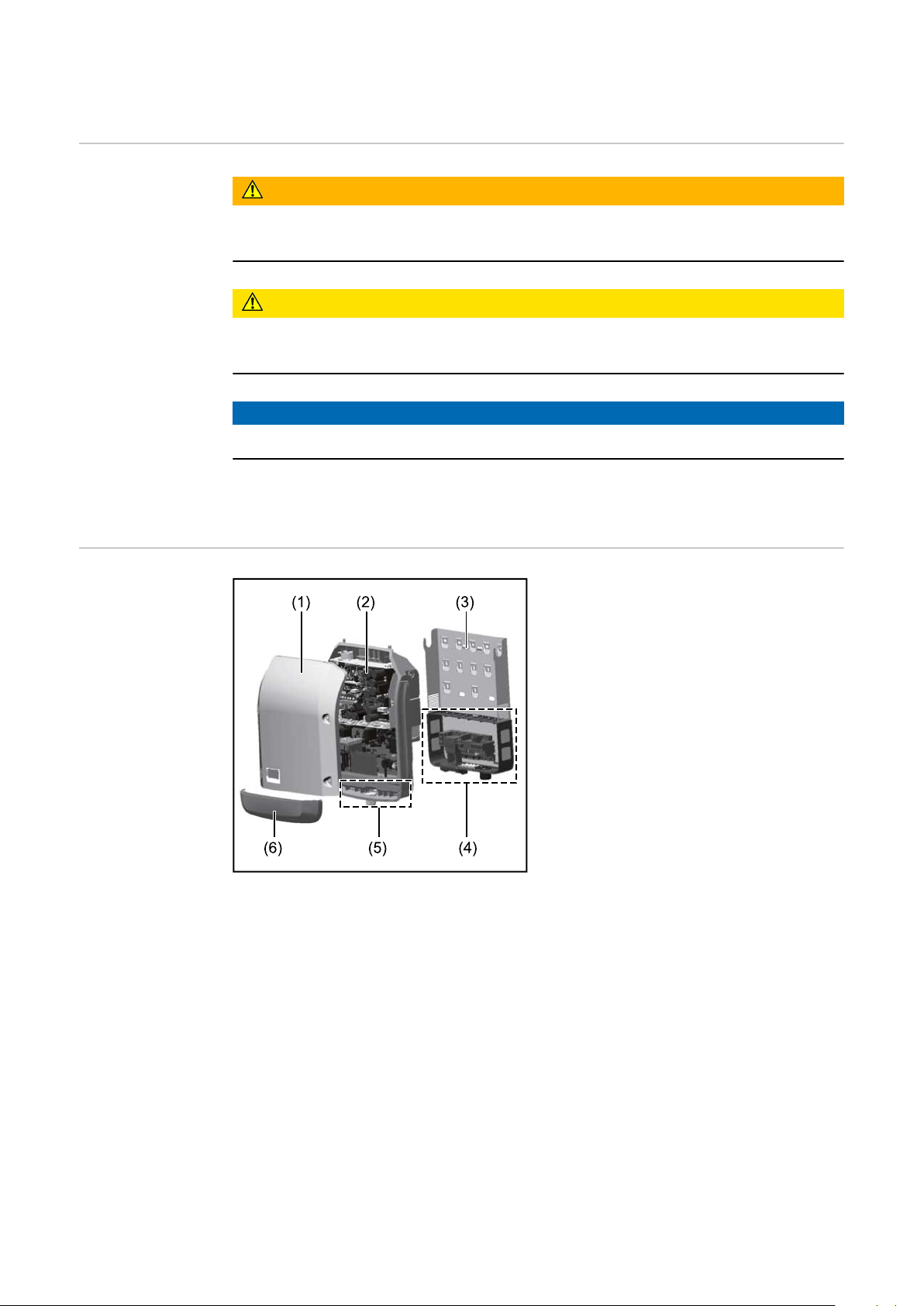
Device concept Device design:
WARNING!
If not avoided, death or serious injury may result.
CAUTION!
If not avoided, minor injury and/or damage to property may result.
NOTE!
(1) Housing cover
(2) Inverter
(3) Mounting bracket
(4) Connection area incl. DC main
switch
(5) Data communication area
(6) Data communication cover
The inverter transforms the direct current generated by the solar modules
into alternating current. This alternating current is fed into the public grid
synchronously with the grid voltage.
The inverter has been developed exclusively for use in grid-connected photovoltaic systems; it is impossible to generate energy independently of the public grid.
The inverter automatically monitors the public grid. In the event of abnormal grid
conditions, the inverter ceases operating immediately and stops feeding power
into the grid (e.g. if the grid is switched off, if there is an interruption, etc.).
The grid is monitored by monitoring the voltage, frequency and islanding conditions.
The inverter operates fully automatically. As soon after sunrise as there is sufficient energy available from the solar modules, the inverter starts monitoring the
grid. When insolation has reached a sufficient level, the inverter starts feeding
energy into the grid.
The inverter operates in such a way that the maximum possible amount of power
is obtained from the solar modules.
As soon as the power available has fallen below the level at which energy can be
8
Page 9

fed into the grid, the inverter disconnects the power electronics completely from
the grid and stops running. It retains all its settings and stored data.
If the inverter becomes too hot, it automatically reduces the current output
power in order to protect itself.
Reasons for the inverter becoming too hot include the ambient temperature being too high or inadequate heat dissipation (e.g. if it is installed in a switch cabinet
without suitable heat dissipation).
EN
Proper use/
intended purpose
The inverter is intended exclusively to convert direct current from solar modules
into alternating current and to feed this into the public grid.
Utilisation not in accordance with the intended purpose comprises:
Any use above and beyond this purpose
-
Making any modifications to the inverter that have not been expressly ap-
-
proved by Fronius
the installation of components that are not distributed or expressly ap-
-
proved by Fronius.
Fronius shall not be liable for any damage resulting from such action.
No warranty claims will be entertained.
Proper use also includes:
Carefully reading and obeying all the instructions and all the safety and
-
danger notices in the Operating Instructions and Installation Instructions
Performing all stipulated maintenance work
-
Installation as specified in the Installation Instructions
-
When designing the photovoltaic system, ensure that all components are operated within their permitted operating ranges at all times.
Observe all the measures recommended by the solar module manufacturer to
ensure that the solar module retains its properties in the long term.
Obey the regulations of the power supply company regarding connection methods and energy fed into the grid.
Warning notices
on the device
There are warning notices and safety symbols on and in the inverter. These warning notices and safety symbols must not be removed or painted over. They warn
against incorrect operation, as this may result in serious injury and damage.
9
Page 10
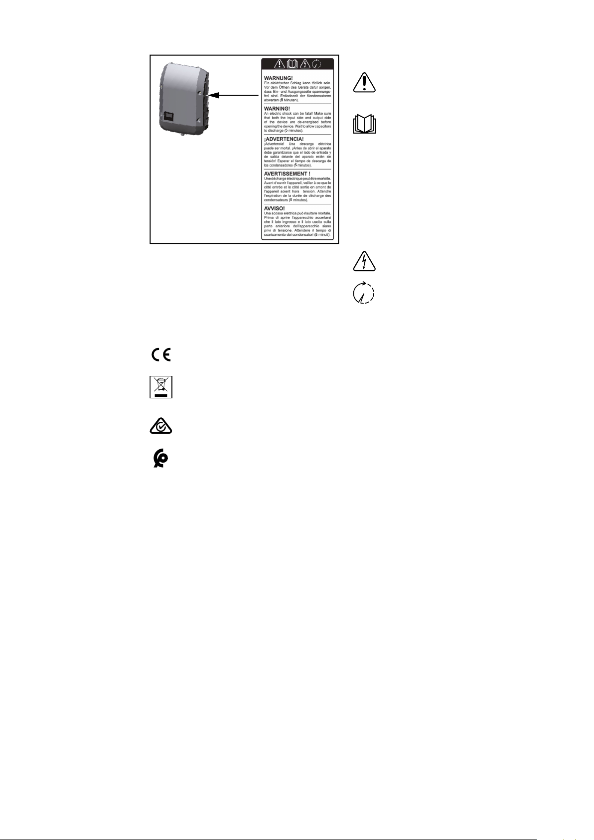
Symbols on the rating plate:
CE mark – confirms compliance with applicable EU directives and
regulations.
Safety symbols:
Danger of serious injury and
damage due to incorrect operation
Do not use the functions de-
scribed here until you have
fully read and understood the
following documents:
These Operating Instruc-
-
tions
All the Operating In-
-
structions for the system
components of the
photovoltaic system, especially the safety rules
Dangerous electrical voltage
Wait for the capacitors to dis-
charge.
WEEE mark – waste electrical and electronic equipment must be
collected separately and recycled in an environmentally sound manner
in accordance with the European Directive and national law.
RCM mark – tested in accordance with the requirements of Australia
and New Zealand.
CMIM mark – tested in accordance with IMANOR requirements for
import regulations and compliance with Moroccan standards.
Text of the warning notices:
WARNING!
An electric shock can be fatal. Before opening the device, it must be disconnected at the input and output. Wait for the capacitors to discharge (5 minutes).
10
Page 11

Data communication and Fronius Solar Net
EN
Fronius Solar
Net and data interface
Fronius Solar Net was developed to make system add-ons flexible to use in a
variety of different applications. Fronius Solar Net is a data network that enables multiple inverters to be linked up using system add-ons.
It is a bus system that uses a ring topology. One suitable cable is sufficient for
communication between one or several inverters that are connected on the
Fronius Solar Net using a system add-on.
Similarly, every inverter on the Fronius Solar Net must be assigned a unique
number.
Refer to the section entitled "The SETUP menu item" for instructions on how
to assign a unique number.
Fronius Solar Net automatically recognises a wide variety of system add-ons.
In order to distinguish between several identical system add-ons, each one
must be assigned a unique number.
More detailed information on the individual system add-ons can be found in
the relevant operating instructions or on the internet at http://www.fronius.com
More detailed information on cabling Fronius DATCOM components can be
found at:
→ http://www.fronius.com/QR-link/4204101938
Data communication area
Depending on the model, the inverter may be equipped with the Fronius
Datamanager plug-in card (8).
11
Page 12

Ite
m Description
(1) Switchable multifunction current interface.
For more details, refer to the section below entitled "Explanation of the
multifunction current interface"
Use the 2-pin mating connector supplied with the inverter to connect to
the multifunction current interface.
(2)
(3)
(4) The "Fronius Solar Net" LED
(5) The "Data transfer" LED
(6) USB A socket
(7) Floating switch contact (relay) with mating connector
IN Fronius Solar Net connection / interface protocol IN
OUT Fronius Solar Net connection / interface protocol
"Fronius Solar Net" / interface protocol input and output for connecting
to other DATCOM components (e.g. inverter, Fronius sensor box, etc.)
If several DATCOM components are linked together, a terminating plug
must be connected to every free IN or OUT connection on a DATCOM
component.
For inverters with a Fronius Datamanager plug-in card, two terminating
plugs are supplied with the inverter.
indicates whether the Fronius Solar Net power supply is available
flashes while the USB flash drive is being accessed. The USB flash drive
must not be removed while recording is in progress.
for connecting a USB flash drive with maximum dimensions of
65 x 30 mm (2.6 x 2.1 in.)
The USB flash drive can function as a datalogger for any inverter that it
is connected to. The USB flash drive is not included in the scope of supply of the inverter.
Explanation of
the multifunction current interface
Max. 250 V AC / 4 A AC
Max. 30 V DC / 1 A DC
Max. 1.5 mm² (AWG 16) cable cross-section
Pin 1 = NO contact (normally open)
Pin 2 = C (common)
Pin 3 = NC contact (normally closed)
For a more detailed explanation, please see the "Menu items in the
Setup menu / Relay" section.
Use the mating connector supplied with the inverter to connect to the
floating switch contact.
(8) Fronius Datamanager with WLAN antenna
or
cover for option card compartment
(9) Cover for option card compartment
Various wiring variants can be connected to the multifunction current interface.
However, these cannot be operated simultaneously. For example, if an S0 meter
is connected to the multifunction current interface, it is not possible to connect
a signal contact for the surge protection device (or vice versa).
12
Page 13

Pin 1 = measurement input: max. 20 mA, 100 Ohm measurement resistor (load
impedance)
Pin 2 = max. short circuit current 15 mA, max. open-circuit voltage 16 V DC or
GND
Wiring diagram variant 1: Signal contact for surge protective device
Depending on the setting in the Basic menu (Signal Input submenu), the DC SPD
option (surge protective device) either outputs a warning or an error on the display. Further information on the DC SPD option can be found in the Installation
Instructions.
Wiring diagram variant 2: S0 meter
A meter for recording the self-consumption of each S0 can be connected directly to the inverter. This S0 meter can be positioned directly at the feed-in point
or in the consumption branch.
IMPORTANT! In order to connect an S0 meter to the inverter, it may be necessary to update the inverter firmware.
EN
Description of
the "Fronius Solar Net" LED
The S0 meter must comply with the IEC62053-31 Class B standard
Recommended max. pulse rate of the S0 meter:
PV output kWp [kW] Max. pulse rate per kWp
30 1000
20 2000
10 5000
≤ 5.5 10000
With this meter, dynamic power reduction can be performed in two ways:
Dynamic power reduction by means of inverter
-
For more information see chapter Dynamic power reduction by means of in-
verter on page 15
Dynamic power reduction by means of the Fronius Datamanager 2.0
-
for more info see: manuals.fronius.com/html/4204260191/
#0_m_0000017472
The "Fronius Solar Net" LED is on:
the power supply for data communication within the Fronius Solar Net / interface protocol is OK
The "Fronius Solar Net" LED flashes briefly every 5 seconds:
data communication error in the Fronius Solar Net
13
Page 14
Overcurrent (current flow > 3 A, e.g. resulting from a short circuit in the
1 2
3
IN
OUT
°C
W/m²
m/s
IN
OUT
IN
OUT
Sensor Box
WLAN
* Fronius Datamanager
*
IN
OUT
-
Fronius Solar Net ring)
Undervoltage (not a short circuit, voltage in Fronius Solar Net < 6.5 V, e.g. if
-
there are too many DATCOM components on the Fronius Solar Net and not
enough electrical power is available)
In this case, power for the Fronius DATCOM components must be supplied
by connecting an additional power supply (43,0001,1194) to one of the
Fronius DATCOM components.
To detect the presence of an undervoltage, check some of the other Fronius
DATCOM components for faults as required.
After cutting out because of overcurrent or undervoltage, the inverter attempts
to restore the power supply in the Fronius Solar Net every 5 seconds while the
fault is still present.
Once the fault is rectified, power to the Fronius Solar Net will be restored within
5 seconds.
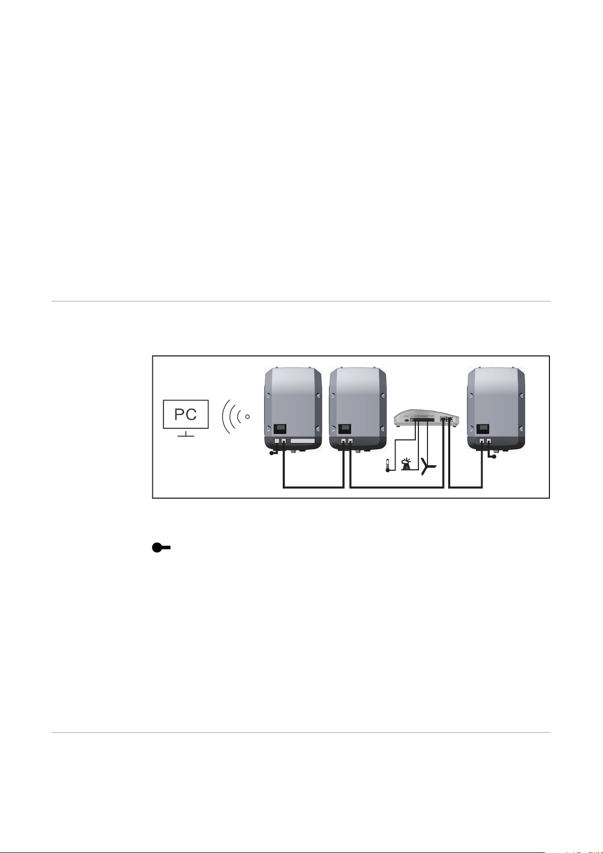
Example Recording and archiving data from the inverter and sensor using a Fronius
Datamanager and a Fronius Sensor Box:
Installing option
cards in the inverter
14
Data network with 3 inverters and a Fronius Sensor Box:
- Inverter 1 with Fronius Datamanager
- Inverters 2 and 3 without Fronius Datamanager!
The external communication (Fronius Solar Net) takes place on the inverter via
the data communication area. The data communication area contains two RS 422
interfaces as inputs and outputs. RJ45 plug connectors are used to make the
connection.
IMPORTANT! Since the Fronius Datamanager functions as a data logger, the
Fronius Solar Net ring must not include any other data logger.
Only one Fronius Datamanager per Fronius Solar Net ring!
Any other Fronius Datamanagers must be removed and the unoccupied option
card compartment sealed off using the blanking cover (42,0405,2020 - available
from Fronius as an optional extra); alternatively, use an inverter without Fronius
Datamanager (light version).
Information on installing option cards (e.g.: Datamanager) in the inverter and
connecting the data communication cable can be found in the Installation Instructions.
= Terminating plug
Page 15

Dynamic power
reduction by
means of inverter
Energy companies or grid operators may impose feed-in limits on an inverter. Dynamic power reduction takes account of self-consumption by the household before the power of an inverter is reduced:
A counter for determining self-consumption of the S0 can be connected directly
to the inverter – see chapter Explanation of the multifunction current interface
on page 12
A feed-in limit can be set in the Basic menu under Signal input – S0 meter – see
chapter Menu items in the Basic menu on page 43.
Setting options for S0 meter:
Grid feed-in limit
-
Field for entering the maximum grid feed-in power in W. If this value is exceeded, the inverter regulates down to the set value within the time required
by national standards and regulations.
Pulses per kWh
-
Field for entering the pulses per kWh of the S0 meter.
Zero feed-in is possible with this configuration.
When using the S0 meter and power reduction by means of an inverter, the S0
meter must be installed in the consumption branch.
EN
S0 meter in the consumption branch
If dynamic power reduction is subsequently configured using the Fronius
Datamanager 2.0 (Inverter user interface - UC Editor menu - Dynamic power reduction), dynamic power reduction must be deactivated using the inverter (Inverter display - Basic menu - Signal input - S0 meter).
15
Page 16

System monitoring
General The inverter is fitted with the WLAN-enabled system monitoring Fronius
Datamanager 2.0 as standard.
The following functions are included with the system monitoring:
Dedicated web page displaying current data and a wide range of settings
-
Ability to connect to Fronius Solar.web using WLAN or LAN
-
Automatic sending of service messages by SMS or e-mail in the event of a
-
fault
Option of controlling the inverter by specifying power limit values, minimum
-
or maximum running times or target running times
Control of the inverter via Modbus (TCP / RTU)
-
Ability to assign control priorities
-
Ability to control the inverter by means of connected meters (Fronius Smart
-
Meter)
Ability to control the inverter via a ripple control signal receiver (e.g. by spe-
-
cifying the reactive power or effective power)
Dynamic power reduction, taking self-consumption into account
-
Further information on Fronius Datamanager 2.0 can be found online in the
Fronius Datamanager 2.0 Operating Instructions.
Fronius
Datamanager
during the night
or when the
available DC
voltage is insufficient
Starting for the
first time
The Night Mode parameter under "Display Settings" in the Setup menu is preset
to OFF in the factory.
For this reason the Fronius Datamanager cannot be accessed during the night or
when the available DC voltage is insufficient.
To nevertheless activate the Fronius Datamanager, switch the inverter off and on
again at the mains and press any function button on the inverter display within
90 seconds.
See also the chapters on "Menu items in the Setup menu", "Display settings"
(Night Mode).
Starting the Fronius Datamanager 2.0 for the first time is made considerably
easier with the Fronius Solar.start app. The Fronius Solar.start app is available in
the respective app stores.
16
When starting the Fronius Datamanager 2.0 for the first time,
the Fronius Datamanager 2.0 plug-in card must be installed in the inverter,
-
or
there must be a Fronius Datamanager Box 2.0 in the Fronius Solar Net ring.
-
IMPORTANT! In order to establish a connection to Fronius Datamanager 2.0,
"Obtain IP address automatically (DCHP)" must be activated on the end device in
question (e.g. laptop, tablet, etc.).
Page 17

NOTE!
Stand by
WiFi Access Point
DATCOM
USB
Clock
If the photovoltaic system has only one inverter, steps 1 and 2 below can be
skipped.
In this case, starting for the first time will commence with step 3.
Connect inverter with Fronius Datamanager 2.0 or Fronius Datamanager Box
1
2.0 to the Fronius Solar Net
When networking several inverters in Fronius SolarNet:
2
Set the Fronius Solar Net client/server switch on the Fronius Datamanager
2.0 plug-in card correctly
One inverter with Fronius Datamanager 2.0 = master
-
All other inverters with Fronius Datamanager 2.0 = slave (the LEDs on
-
the Fronius Datamanager 2.0 plug-in cards are not illuminated)
Switch the device to Service mode
3
Activate the WiFi Access Point via the Setup menu on the inverter
-
EN
The inverter establishes the WLAN access point. The WLAN access point remains open for 1 hour. The IP switch on the Fronius Datamanager 2.0 can remain
in switch position A due to the activation of the WiFi Access Point.
Installation using the Solar.start
Installation using a web browser
app
Download Fronius Solar.start
4
Connect the end device to the
4
WLAN access point
SSID = FRONIUS_240.xxxxx (5-8
digits)
Search for a network with the
-
name "FRONIUS_240.xxxxx"
Establish a connection to this
Run the Fronius Solar.start app
5
-
network
Enter the password 12345678
-
(Alternatively, connect the end
device and inverter using an Ethernet cable.)
Enter the following in the
5
browser:
http://datamanager
or
192.168.250.181 (IP address for
WLAN connection)
or
169.254.0.180 (IP address for
LAN connection)
17
Page 18

The Setup wizard start page is displayed.
The technician wizard is intended for the installer and contains standard-specific
settings. Running the technician wizard is optional.
If the technician wizard is run, it is vital to note the service password that is issued. This service password is necessary for setting the "DNO Editor" menu item.
If the technician wizard is not run, no specifications regarding power reduction
are set.
Further information on Fronius
Datamanager 2.0
Running the Fronius Solar.web wizards is mandatory.
Run the Fronius Solar.web wizards and follow the instructions
6
The Fronius Solar.web homepage is displayed,
or
the Fronius Datamanager 2.0 web page is displayed.
Where necessary, run the technician wizard and follow the instructions
7
Further information on the Fronius Datamanager 2.0 and other start-up options can be found at:
→ http://www.fronius.com/QR-link/4204260191DE
18
Page 19
Controls and indicators
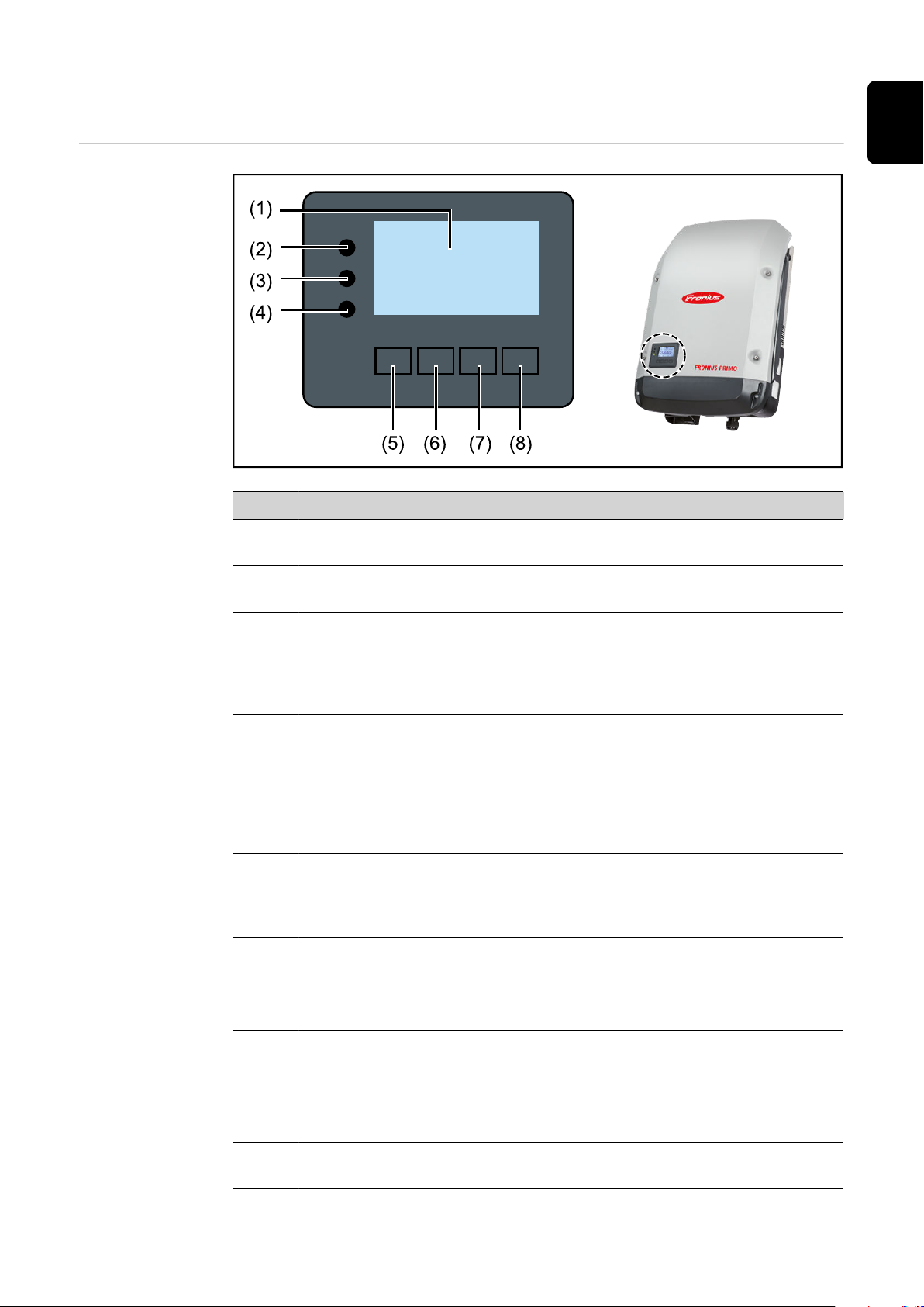
Controls and displays
Item Description
(1) Display
For displaying values, settings and menus
EN
Monitoring and status LEDs
(2) General status LED (red) lights up
if a status message is being displayed on the monitor
-
If the process of feeding energy into the grid is interrupted
-
During error handling (the inverter waits for an acknowledge-
-
ment or for an error to be rectified)
(3) Startup LED (orange) lights up
If the inverter is in its automatic startup or self-test phase (as
-
soon after sunrise as the solar modules are delivering sufficient
power)
If the inverter has been switched to Standby mode in the Setup
-
menu (= feeding energy into the grid switched off manually)
If the inverter software is being updated
-
(4) Operating status LED (green) lights up
If the PV system is working correctly after the inverter's auto-
-
matic startup phase
all the time while energy is being fed into the grid
-
Function keys - allocated different functions depending on the selection:
(5) "Left/up" key
For navigating to the left and up
(6) "Down/right" key
For navigating down and to the right
(7) "Menu/Esc" key
For switching to the menu level
For quitting the Setup menu
(8) "Enter" key
For confirming a selection
19
Page 20

The keys are capacitive and any exposure to water can impair their function. Wipe
the keys dry with a cloth if necessary to ensure optimum functionality.
Display Power for the display comes from the mains voltage. Depending on the setting
selected in the Setup menu, the display can be kept on all day.
IMPORTANT! The display on the inverter is not a calibrated measuring device.
A slight inaccuracy in comparison with the energy meter used by the energy
company is intrinsic to the system. A calibrated meter will be needed to calculate
the bills for the power supply company.
Display areas in Display mode
Display areas in Setup mode
(*) Scroll bar
(**) The Energy Manager symbol
is displayed when the Energy Manager function is activated
(***) Inv. no. = Inverter DATCOM number,
Save symbol - appears briefly while set values are being saved,
USB connection - appears if a USB stick has been connected
20
Page 21
The menu level
EN
Activating display backlighting
Automatic deactivation of display backlighting / changing to
the "NOW" menu
item
Open menu level
Press any key
1
The display backlighting is activated.
There is an option under "Display Settings - Backlighting" in the SETUP menu
to set the display backlighting so that it is on all the time or off all the time.
If two minutes pass without any button being pressed, the display backlighting
switches off automatically and the inverter goes to the "NOW" menu item (assuming the display backlighting is set to AUTO).
The automatic selection of the "NOW" menu item can happen from any position
on the menu level, unless the inverter was manually switched into the "Standby"
operating mode.
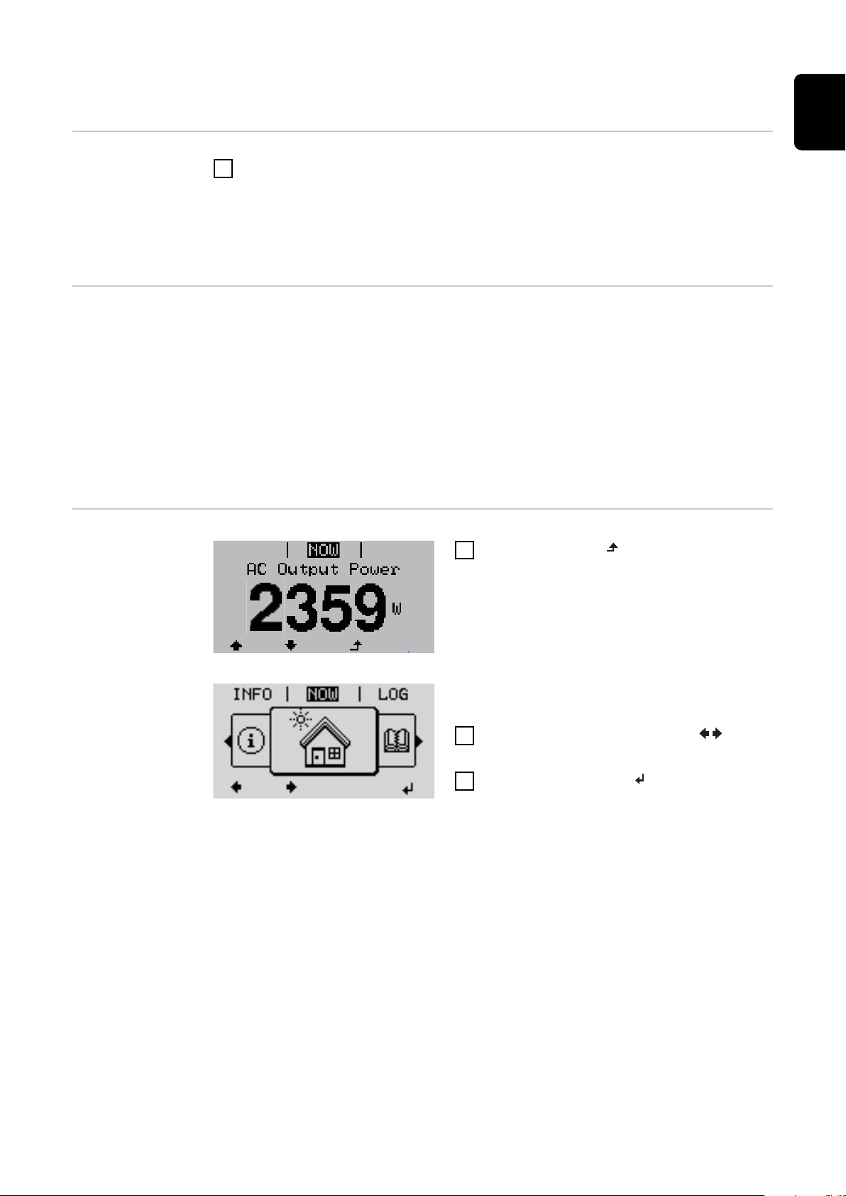
After automatically selecting the "NOW" menu item, the current power of feeding in is displayed.
1
Press the "Menu" key
The display switches to the menu level.
2
Using the "Left" or "Right" keys select the desired menu item
3
Press the "Enter" key to select the
desired menu item
21
Page 22
The NOW, LOG and GRAPH menu items
GRAPH
GRAPH
NOW
LOG
GRAPH
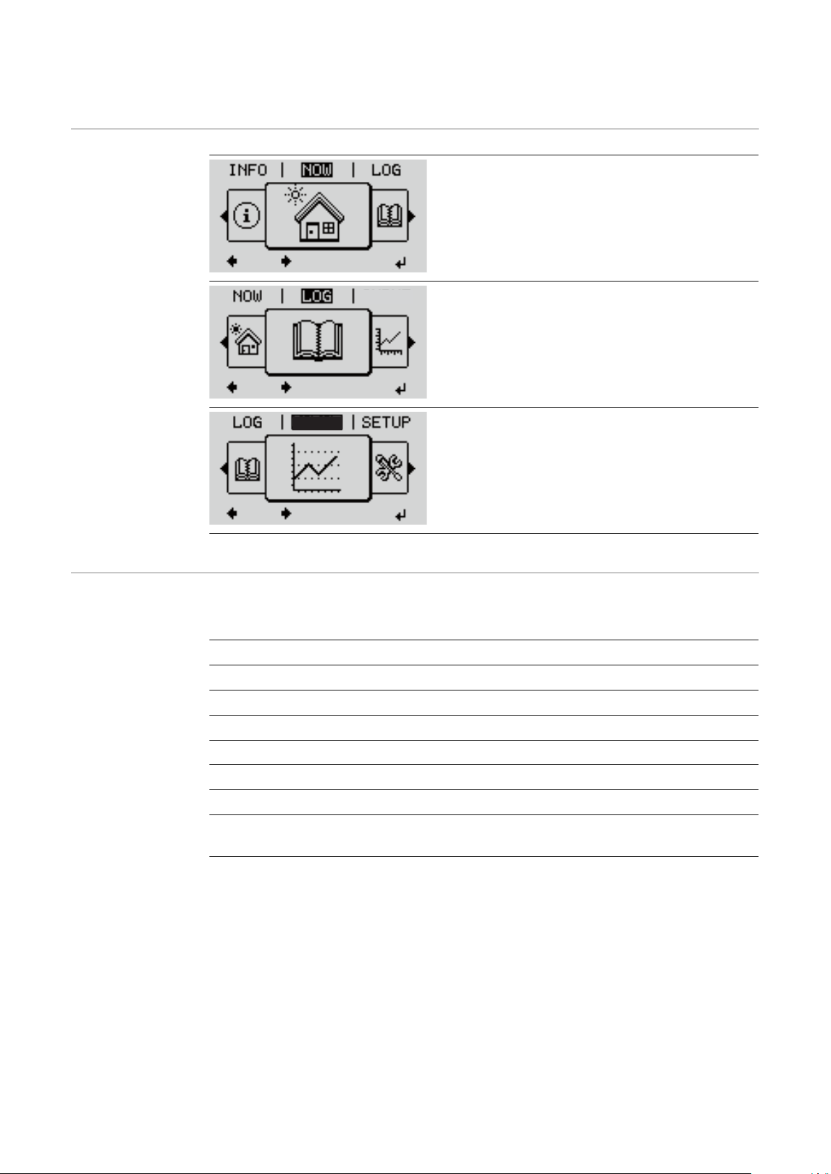
NOW
(Displays real-time values)
LOG
(Data recorded today, during the current calendar year and since the inverter was first
commissioned)
GRAPH
Day characteristic
displays a plot showing the output power
during the day. The time axis is scaled automatically.
Press the "Back" key to close the display
Values displayed
in the NOW and
LOG menu items
Values displayed in the NOW menu item:
AC Output power (W)
AC Reactive power (V Ar)
AC Voltage (V)
AC Output current (A)
AC Frequency (Hz)
PV Array Voltage (V)
PV Array Current (A)
Time / date
Time and date on the inverter or in the Fronius Solar Net ring
22
Page 23

Values displayed in the LOG menu item:
(for today, during the current calendar year and since the inverter was started
for the first time)
AC Energy Yield (kWh / MWh)
Energy fed into the grid during the period in question
There may be discrepancies with values displayed on other measuring instruments because of differences in measuring methods. As far as the billing of
the energy fed in is concerned, the only binding display values are those produced by the calibrated measuring device provided by the electricity supply
company.
AC Max. Output Power (W)
Largest amount of power fed into the grid during the period in question
Earnings
Amount of money earned during the period in question (currency can be selected in the Setup menu)
Like the energy supplied figure, the yield figure may also exhibit discrepancies
with other measured values.
The 'Setup Menu' section explains how to select a currency and charge rate.
The factory setting depends on the respective country setup.
EN
CO2 savings (g / kg)
CO2 emissions saved during the period in question
The value for CO2 savings depends on the power station facilities and corresponds to the CO2 emissions that would be released when generating the same
amount of energy. The factory setting is 0.53 kg / kWh (source: DGS –
Deutsche Gesellschaft für Sonnenenergie e.V. (German Society for Solar Energy).
AC Max. Voltage L-N (V)
Highest voltage measured between the conductor and neutral conductor during the period in question
PV Array Max. Voltage (V)
Highest solar module voltage measured during the period in question
Operating Hours
Length of time the inverter has been working (HH:MM).
IMPORTANT! A prerequisite for the correct display of day and year values is
that the time is set correctly.
23
Page 24

SETUP menu item
GRAPH
GRAPH
Relay
Initial setting The inverter is pre-configured after commissioning has been completely carried
out (e.g. using the Installation Wizard) according to the country setup.
The SETUP menu item allows the initial settings of the inverter to be changed
easily to bring it in line, as closely as possible, with the preferences and requirements of the user.
SETUP
Navigating the
SETUP menu
item
SETUP
(Setup menu)
NOTE!
As a result of software updates, you may find that your device has certain functions that are not described in these Operating Instructions, or vice versa.
Certain illustrations may also differ slightly from the actual controls on your
device, but these controls function in exactly the same way.
Entering the SETUP menu item
At the menu level, use the "Left" or
1
"Right" keys to select the "SETUP"
menu item
2
Press the "Enter" key
Menu level, "SETUP" selected
The first entry under the SETUP menu item
is displayed:
"Standby"
"Standby" entry
Scrolling between the entries
24
Page 25

Relay
3
GRAPH
Use the "Up" and "Down" keys to
scroll between the available entries
Example: "WiFi Access Point" menu item
Exiting an entry
To exit a menu entry, press the "Back"
4
key
The menu level appears
If no key is pressed for 2 minutes:
The inverter switches from wherever it is on the menu level back to the
-
"NOW" display mode (exception: "Standby" Setup menu entry),
The display backlighting goes out.
-
The amount of power currently being fed in is displayed.
-
EN
Setting menu
entries, general
Open the desired menu
1
2
Use the 'Up' or 'Down' keys to select the desired menu item
3
Press "Enter"
The available settings are displayed: The first digit of a value to be set
flashes:
Use the 'Up' or 'Down' buttons to
4
select the desired setting
Press the 'Enter' key to save and
5
Use the 'Up' or 'Down' keys to se-
4
lect a value for the first digit
5
Press "Enter"
apply the setting.
The second digit of the value flashes.
To discard the setting, press the
Repeat steps 4 and 5 until ...
'Esc' key.
6
the whole value to be set flashes.
7
Press "Enter"
Repeat steps 4 - 6 as required for
8
units or other values that are to
be set until the appropriate unit
or the value flashes.
Press the 'Enter' key to save and
9
apply the changes.
To discard the changes, press the
'Esc' key.
25
Page 26

The currently selected menu item is
displayed.
The currently selected menu item is
displayed.
Application example: Setting
the time
Select "Clock" from the Setup menu
1
.
2
Press the "Enter" key
An overview of the values that can be
changed is displayed.
3
Use the "Up" and "Down" keys Select
"Set time"
4
Press the "Enter" key
The current time appears. (HH:MM:SS, 24hour clock), the "tens" digit for the hour will
flash.
5
Use the "Up" and "Down" keys to select a value for the first digit of the code
6
Press the "Enter" key
The "units" digit for the hour will flash.
Repeat steps 5 and 6 to set the "units"
7
digit for the hour, for the minutes and for
the seconds until...
the set time starts flashing.
8
Press the "Enter" key
The time is applied and the overview of values that can be changed is displayed.
4
Press the "Esc" key
26
Page 27

The "Clock" item on the Setup menu appears.
EN
27
Page 28

The Setup menu items
Standby Manual activation / deactivation of Standby mode
No energy is fed into the grid.
-
The Startup LED will show steady orange.
-
In the display, STANDBY / ENTER are alternately displayed
-
In Standby mode, no other menu item at menu level can be accessed or ad-
-
justed.
The automatic switchover into the "NOW" display mode after 2 minutes of
-
keyboard inactivity does not occur.
Standby mode can only be terminated manually by pressing the "Enter" key.
-
Pressing "Enter" at any time will cause energy to resume feeding into the
-
grid, as long as there is no error (state code)
Switching off Standby mode (manually switching off feeding energy into the
grid):
Select the "Standby" item
1
2
Press "Enter" function key
"STANDBY" and "ENTER" appear alternately on the display.
Standby mode is now active.
The Startup LED shows steady orange.
WiFi Access
Point
Resuming feeding energy into the grid:
In standby mode, the display alternates between 'STANDBY' and 'ENTER'.
1
Press the "Enter" function key to resume feeding energy into the grid
The "Standby" menu item is displayed.
At the same time, the inverter enters the startup phase.
The operating state LED shows steady green when feeding energy into the grid
has been resumed.
Activating / deactivating the WiFi Access Point. This is necessary for setting up
or adjusting system monitoring using the Datamanager web interface, for example. If no Datamanager is detected by the inverter, [not available] is displayed
Setting range WiFi Access Point
[stopped]
Activate WiFi AP?
To activate the WiFi Access Point Press the "Enter"
key
WiFi Access Point
[active]
28
The SS-ID (SS) and password (PW) are displayed.
Deactivate WiFi AP?
To deactivate the WiFi Access Point Press the
"Enter" key
Page 29

DATCOM Checking data communications, entering the inverter number, protocol settings
Setting range Status / inverter number / protocol type
Status
Indicates data communication is taking place via Fronius Solar Net or that a
data communications error has occurred
Inverter number
Sets the number (= address) of the inverter in a system with several inverters
Setting range 00 - 99 (00 = inverter address 100)
Factory setting 01
WiFi Access Point
[not available]
Displayed if there is no system monitoring present on
the inverter.
EN
IMPORTANT! If a number of inverters are linked together in a data communic-
ations system, assign a unique address to each one.
Protocol type
Specifies the communications protocol to be used to transfer the data:
Setting range Solar Net / Interface *
Factory setting Fronius Solar Net
* The protocol type "Interface" only functions when there is no Datamanager
card in the inverter. All Fronius Datamanager cards should be removed from
the inverter.
USB Running firmware updates or saving detailed information from the inverter to the
USB flash drive
Setting range Safely remove hardware / Software update / Logging in-
terval
Safely remove hardware
To remove a USB flash drive from the USB A socket on the plug-in data communications card without losing any data.
The USB flash drive can be removed:
If the OK message appears
-
when the "Data transfer" LED stops flashing or comes on steady
-
Software update
To update the inverter firmware using a USB flash drive.
29
Page 30
Procedure:
Download the relevant firmware update file "froxxxxx.upd"
1
(e.g. from http://www.fronius.com; xxxxx stands for the version number)
NOTE!
To successfully update the inverter software, the USB flash drive provided for
the purpose must not have a hidden partition or any encryption (see chapter
"Suitable USB flash drives").
Save the firmware update file to the highest data level of the USB flash drive
2
Open the lid of the data communication area on the inverter
3
Plug the USB flash drive containing the firmware update file into the USB
4
socket in the inverter's data communication area
Select "USB" from the Setup menu, followed by "Software update"
5
Press the "Enter" key
6
Wait until the version currently installed on the inverter and the new firm-
7
ware version are displayed for comparison:
First Page: Recerbo software (LCD), key controller software (KEY), coun-
-
try setup version (Set)
Second Page: Power stage set software (PS1/PS2)
-
Press the "Enter" function button after each page
8
The inverter starts copying the data.
"BOOT" and the progress of storing the individual tests expressed in % are displayed until all the data for all the electronic modules has been copied.
Once copying is complete, the inverter updates the electronic modules as required in sequence.
"BOOT", the affected modules and the update progress in % are displayed.
The final step is for the inverter to update the display.
The display remains dark for approx. 1 minute while the monitoring and status
LEDs flash.
Once the firmware update is complete, the inverter enters its start-up phase before going on to start feeding energy into the grid. Unplug the USB flash drive using the "Safely remove hardware" function.
When the inverter firmware is updated, any custom settings that were configured
in the Setup menu are retained.
30
Page 31

Logging interval
Activate / deactivate the USB logging function and specify a logging interval
Unit Minutes
Setting range 30 min. / 20 min./ 15 min./ 10 min./ 5 min./ No log
Factory setting 30 min.
30 min. The logging interval is 30 minutes; every 30 minutes new
logging data will be saved to the USB flash drive.
20 min.
15 min.
10 min.
5 min. The logging interval is 5 minutes; every 5 minutes new
logging data will be saved to the USB flash drive.
No log No data is saved
IMPORTANT! In order for the USB logging function to work correctly the time
must be set correctly. Setting the time is discussed in the section "Menu items in
the Setup menu" - "Clock".
EN
Relay (floating
contact switch)
Status codes (state codes), the status of the inverter (e.g. feeding energy into the
grid) or Energy Manager functions can be displayed using the floating switch contact (relay).
Setting range Relay mode / Relay test / Switch-on point* / Switch-off
point*
* these are only shown if the "E-Manager" function has been activated under "Relay mode".
Relay mode
The following functions can be shown using relay mode:
Alarm function (Permanent / ALL / GAF)
-
Active output (ON / OFF)
-
Energy Manager (E-Manager)
-
Setting range ALL / Permanent / GAF / OFF / ON / E-Manager
Factory setting ALL
Alarm function:
ALL / Permanent:
Switching the floating switch contact for permanent and temporary service codes (e.g. brief interruption to energy being
fed into the grid, a service code occurs a certain number of
times a day - can be adjusted in the "BASIC" menu)
31
Page 32

GAF As soon as GAF mode is selected, the relay is switched on.
The relay opens as soon as the power stage set registers an
error and goes from normally feeding energy into the grid to
being in an error state. This means that the relay can be used
for fail-safe functions.
Application example
It may be necessary to perform phase compensation when using a single-phase inverter at a multiphase site. If an error occurs on one or several inverters and the connection to the grid
is broken, the other inverters must also be disconnected to
maintain the phase balance. The "GAF" relay function can be
used in conjunction with the Datamanager or an external protection device to recognise or signal that an inverter is not
feeding in or is disconnected from the grid and to then disconnect the remaining inverters from the grid using a telecontrol command.
Active output:
ON: The floating NO contact is on all the time the inverter is in op-
eration (as long as the display is not dark or is displaying
something).
OFF: The floating NO contact is off.
Energy Manager:
E-Manager: Further details on the "Energy Manager" function may be
found in the "Energy Manager" section.
Relay test
Function test to determine whether the floating switch contact switches
Switch-on point (only if "Energy Manager" function is activated)
for setting the effective power limit beyond which the floating switch contact is
switched on
Factory setting 1000 W
Setting range Set switch-off point up to the maximum nominal output
of the inverter (W or kW)
Switch-off point (only if "Energy Manager" function is activated)
for setting the effective power limit beyond which the floating switch contact is
switched off
Factory setting 500
Setting range 0 to the set switch-on point of the inverter (W or kW)
Energy Manager
(under Relay
menu item)
32
The "Energy Manager" (E-Manager) function can be used to activate the floating
switch contact in such a way that it functions as an actuator.
Thus, a consumer that is connected to the floating switch contact can be controlled by specifying a switch-on or switch-off point that depends on the feed-in
power (effective power).
The floating switch contact is automatically switched off:
If the inverter is not feeding any power into the grid
-
If the inverter is manually switched to Standby mode
-
If the effective power is set to < 10% of the nominal output of the inverter.
-
Page 33

To activate the Energy Manager function, select the "E-Manager" item and press
the "Enter" key.
When the "Energy Manager" function is running, the "Energy Manager" symbol
will appear in the top left corner of the display:
When the floating NO contact is off (open contact)
When the floating NC contact is on (closed contact)
To deactivate the Energy Manager function, select a different function (ALL /
Permanent / OFF / ON) and press the "Enter" key.
NOTE!
Notes on setting up the switch-on and switch-off points
If the difference between the switch-on and switch-off points is too small, or if
there are fluctuations in effective power, the result may be multiple switching
cycles.
To avoid switching on and off frequently, the difference between the switch-on
and switch-off points should be at least 100 - 200 W.
When choosing the switch-off point, the power consumption of the connected
consumer should be taken into account.
EN
When choosing the switch-on point, the weather conditions and anticipated insolation should be taken into account.
Application example
Switch-on point = 2000 W, switch-off point = 1800 W
If the inverter is outputting 2000 W or above, then the floating switch contact on
the inverter is switched on.
If the inverter output falls to below 1800 W, the floating switch contact is
switched off.
This allows useful applications, such as operating a heat pump or an air-conditioning system using as much self-generated power as possible, to be implemented quickly
Time / Date Set the time, date, the display format and automatic changeover between sum-
mer and winter time
Setting range Set time / Set date / Time display format / Date display
format / Summer/winter time
Set time
Set the time (hh:mm:ss or hh:mm am/pm – depending on the setting for the
time display format)
Set date
Set the date (dd.mm.yyyy or mm/dd/yyyy - depending on the setting for the
date display format)
Time display format
For specifying the time display format
33
Page 34

Setting range 12hrs / 24hrs
Factory setting Depends on country setup
Date display format
for specifying the date display format
Setting range mm/dd/yyyy or dd.mm.yy
Factory setting Depends on country setup
Summer/winter time
Activate/deactivate automatic changeover between summer and winter time
IMPORTANT! Only use the automatic summer/winter time changeover function if the Fronius Solar Net ring does not include any LAN- or WLAN-compatible system components (e.g. Fronius Datalogger Web, Fronius Datamanager or
Fronius Hybridmanager).
Setting range on / off
Factory setting on
IMPORTANT! The time and date must be set accurately in order for the day
and year values and for the day characteristic to be displayed correctly.
Display settings
Setting range Language / Night mode / Contrast / Illumination
Language
Set language for display
Setting range English, German, French, Spanish, Italian, Dutch,
Czech, Slovakian, Hungarian, Polish, Turkish, Por-
tuguese, Romanian
Night mode
Night mode controls Fronius DATCOM and inverter display operation during
the night or when the DC voltage is insufficient
Setting range AUTO / ON / OFF
Factory setting OFF
AUTO: Fronius DATCOM mode is always in effect as long as there is a
Fronius Datamanager connected in an active and uninterrupted
Fronius Solar Net.
The inverter display remains dark during the night, but can be activated by pressing any function button.
34
Page 35

ON: Fronius DATCOM mode is always in effect. The inverter supplies 12
V of DC voltage continuously to power the Fronius Solar Net. The
display is always active.
IMPORTANT! If Fronius DATCOM night mode is set to ON or
AUTO when there are Fronius Solar Net components connected,
the inverter's current consumption during the night will increase to
around 7 W.
OFF: Fronius DATCOM will not run at night, the inverter therefore does
not require any power during the night to supply the Fronius Solar
Net with energy.
The inverter display is switched off during the night and the Fronius
Datamanager is not available. To nevertheless activate the Fronius
Datamanager, switch the inverter off and on again at the mains and
press any function button on the inverter display within 90
seconds.
Contrast
Set the contrast on the inverter display
Setting range 0 - 10
Factory setting 5
EN
Since the contrast is temperature-dependent, it may be necessary to adjust
the setting under the "Contrast" menu item when the environmental conditions
change.
Illumination
Initial setting for inverter display illumination
The "Illumination" menu item only relates to the inverter display backlighting.
Setting range AUTO / ON / OFF
Factory setting AUTO
AUTO: The inverter display backlighting is activated by pressing any key. If
no key is pressed for 2 minutes, the display backlighting will go off
again.
ON: The inverter display backlighting remains permanently on when the
inverter is active.
OFF: The inverter display backlighting is permanently switched off.
ENERGY YIELD The following settings can be changed/set here:
Counter deviation / Calibration
-
Currency
-
Feed-in tariff
-
CO2 factor
-
Setting range Currency / Feed-in tariff
35
Page 36

Counter deviation / calibration
Calibrating the counter
Currency
Set the currency
Setting range 3 characters, A-Z
Feed-in tariff
Set the remuneration rate for energy fed into the grid
Setting range 2 digits, 3 decimal places
Factory setting (depends on country setup)
CO2 factor
Setting the CO2 factor of the energy fed into the grid
Fan To check that the fan is working correctly
Setting range Test fan #1 / Test fan #2 (depending on the device)
Use the "Up" and "Down" keys to select the desired fan
-
Testing of the selected fan is initiated by clicking "Enter".
-
The fan will continue to run until the operator exits the menu by pressing
-
"Esc".
IMPORTANT! Nothing will show on the inverter display if the fan is working. The
only way to check how the fan is working is by listening and feeling.
36
Page 37

The INFO menu item
EN
INFO
Measured values
PSS status
Grid status
Measured values
INFO
(Information about the device and the software)
Display range: PV ins. / Ext. lim. / U PV1 / U PV2 /
GVDPR / Fan #1
PV ins.
Insulation resistance of the PV system
(with unearthed solar modules and solar modules with negative pole earthing)
Ext. lim.
External power reduction in per cent e.g. specified by grid operator
U PV1
Current DC voltage on the terminals, even if the inverter is
feeding no power into the grid whatsoever (from the 1st MPP
tracker)
PSS status The status of the most recent inverter fault can be displayed.
Grid status The five most recent grid faults can be displayed:
U PV2
Current DC voltage on the terminals, even if the inverter is
feeding no power into the grid whatsoever (from the 2nd MPP
tracker)
GVDPR
Grid voltage-dependent power reduction
Fan #1
Percentage of target output for fan
IMPORTANT! Due to the low level of insolation early in the
morning and in the evening, the status codes 306 (Power low)
and 307 (DC low) are displayed routinely at these times of
day. These status codes do not indicate any kind of fault.
Press the "Enter" key to see the status of the power stage
-
set and the most recent fault
Use the "Up" and "Down" keys to scroll through the list
-
Press the "Back" key to close the status and fault list
-
Press the 'Enter' key to see the five most recent grid
-
faults
Use the "Up" and "Down" keys to scroll through the list
-
Press the 'Back' key to close the grid fault display
-
37
Page 38

Device information
Display area General / Country-specific setting / MPP tracker / Grid monitoring / Grid
General: Device type - the exact name of the inverter
For displaying the settings that will be of relevance to a power supply company.
The values shown will depend on the country setup or the device-specific settings of the inverter.
voltage limits / Grid frequency limits / Q-mode / AC power limit / AC voltage
derating / Fault Ride Through
fam. - inverter family of the inverter
serial number - serial number of the inverter
Country-specific
setting:
MPP Tracker: Tracker 1 - indicates the set tracking behaviour (MPP AUTO / MPP USER /
Grid monitoring: GMTi - Grid Monitoring Time - start-up time of the inverter in sec (seconds)
Setup - specified country setup
Version - version of country setup
Origin activated - indicates that the normal country-specific setup is activated.
Alternat. activated - indicates that the alternative country-specific setup is
activated (for Fronius Symo Hybrid only)
Group - group for updating the inverter software
FIX)
Tracker 2 (only on Fronius Symo except for Fronius Symo 15.0-3 208) - indicates the set tracking behaviour (MPP AUTO / MPP USER / FIX)
GMTr - Grid Monitoring Time reconnect - reconnection time in sec (seconds)
after a grid fault
ULL - U (voltage) Longtime Limit - voltage limit value in V (volts) for the 10minute average voltage value
LLTrip - Longtime Limit Trip - trip time for ULL monitoring, how fast the inverter should switch off
Grid voltage limits
inner limit value:
38
UImax - upper inner grid voltage in V (volts)
TTMax - Trip Time Max - trip time for exceeding the upper inner grid voltage
limit value in cyl*
UMin - lower inner grid voltage in V (volts)
TTMin - Trip Time Min - trip time for falling below the lower inner grid
voltage limit value in cyl*
*cyl = grid periods (cycles); 1 cyl corresponds to 20 ms at 50 Hz or 16.66 ms
at 60 Hz
Page 39

Grid voltage limits
outer limit value
UMax - upper outer grid voltage in V (volts)
TTMax - Trip Time Max - trip time for exceeding the upper outer grid voltage
limit value in cyl*
UMin - lower outer grid voltage in V (volts)
TTMin - Trip Time Min - trip time for falling below the lower outer grid
voltage limit value in cyl*
*cyl = grid periods (cycles); 1 cyl corresponds to 20 ms at 50 Hz or 16.66 ms
at 60 Hz
EN
Grid frequency limits:
Q-mode: Indicates which reactive power setting is currently active on the inverter (e.g.
AC power limit including SoftStart indicator and/or AC
grid frequency derating:
AC voltage derating: GVDPRe - Grid Voltage Depending Power Reduction enable limit - threshold
FILmax - upper inner grid frequency in Hz (Hertz)
FILmin - lower inner grid frequency in Hz (Hertz)
FOLmax - upper outer grid frequency in Hz (Hertz)
FOLmin - lower outer grid frequency in Hz (Hertz)
OFF, Q / P, etc.)
Max P AC - maximum output power, which can be changed using the "Manual Power Reduction" function
GPIS - Gradual Power Incrementation at Startup - indicates (%/sec) whether the SoftStart function is active on the inverter
GFDPRe - Grid Frequency Dependent Power Reduction enable limit - indicates the set grid frequency in Hz (Hertz) from when power derating takes
place
GFDPRv - Grid Frequency Dependent Power Reduction derating gradient indicates the set grid frequency in %/Hz, how strong power derating is
value in V from which voltage-dependent power derating starts
GVDPRv - Grid Voltage Depending Power Reduction derating gradient - derating gradient %/V with which the power is reduced
Message - indicates whether the dispatch of an info message via Fronius Solar Net is active
Version Displays the version and serial numbers of the PC boards in the inverter (e.g. for
service purposes)
Display area Display / Display Software / Integrity Checksum /
Memory Card / Memory Card #1 / Power Stage / Power
Stage Software / EMI Filter / Power Stage #3 / Power
Stage #4
39
Page 40

Switching the key lock on and off
Acess Code
General The inverter has a key lock function.
When the key lock is active, the Setup menu is not accessible, i.e. the setup data
cannot be changed accidentally (or maliciously).
The code 12321 has to be entered in order to activate / deactivate the key lock.
Switching the
key lock on and
off
1
Press the "Menu" key
The menu level appears.
Press the unassigned "Menu / Esc" key
2
5 times
"Access Code" is displayed in the "CODE"
menu; the first digit starts flashing.
Enter the code 12321: Use the "Plus" and
3
"Minus" keys to select a value for the
first digit of the code
4
Press the "Enter" key
The second digit flashes.
Repeat steps 3 and 4 for the second,
5
third, fourth and fifth digits of the access
code until...
the selected code starts flashing.
6
Press the "Enter" key
"Setup Menu Lock" is displayed in the
"LOCK" menu.
7
Use the "Plus" and "Minus" keys to
turn the key lock on or off:
ON = key lock is on (the Setup menu is
not accessible)
OFF = key lock is off (the Setup menu is
accessible)
8
Press the "Enter" key
40
Page 41

USB Stick as a Data Logger and for Updating Inverter Software
USB flash drive
as a datalogger
If a USB flash drive is connected to the USB A socket it can function as a datalogger for an inverter.
At any time, the logging data stored on the USB flash drive can be
imported into the Fronius Solar.access software using the FLD file that was
-
logged at the same time,
viewed directly in third-party programs (e.g. Microsoft® Excel) using the CSV
-
file logged at the same time.
Older versions (before Excel 2007) are limited to a maximum of 65,536 rows.
Further information on "Data on a USB flash drive", "Data volume and storage
capacity" as well as "Buffer memory" can be found at:
EN
® http://www.fronius.com/QR-link/4204260204DE
Suitable USB
flash drives
Due to the variety of USB flash drives available on the market, it cannot be guaranteed that every USB flash drive will be detected by the inverter.
Fronius recommends that only certified, industry-grade USB flash drives are
used (look out for the USB-IF logo).
The inverter supports USB flash drives with the following file systems:
FAT12
-
FAT16
-
FAT32
-
Fronius recommends that the USB flash drive employed should only be used for
recording logging data or updating the inverter software. The USB flash drives
should not contain any other data.
41
Page 42

USB symbol on the inverter display, e.g. in display mode 'NOW':
AC Output Power
NOW
Do not disconnect
USB-Stick
while LED is flashing!
X
If the inverter detects a USB flash
drive, the USB symbol will appear in
the top right corner of the display.
When inserting a USB flash drive,
check whether the USB symbol is displayed (it may also flash).
Note! Please note for outdoor applications that conventional USB flash drives
are often only guaranteed to work within a restricted temperature range.
For outdoor applications ensure that the USB flash drive also functions, for example, at low temperatures.
USB stick for updating the inverter software
Removing the
USB flash drive
With the help of the USB stick, end customers can also update the inverter software via the USB item on the SETUP menu: the update file is first saved to the
USB stick, from where it is then transferred to the inverter. The update file must
be saved in the root directory on the USB stick.
Safety instruction concerning the removal of a USB flash drive:
IMPORTANT! To avoid any loss of
data, a USB flash drive may only be
removed if the following conditions
are met:
Only remove a USB flash drive
-
via the 'Safely remove USB /
HW' item on the SETUP menu
The 'Data transmission' LED has
-
stopped flashing or comes on
steady.
42
Page 43

The Basic menu
Access Code
General The Basic menu is used to set the following parameters, which are important for
installing and operating the inverter:
EN
Access the Basic
menu
DC operating mode
-
Fixed voltage
-
MPPT1 / MPPT2 start voltage
-
USB logbook
-
Event counter
-
Grounding mode / grounding
-
monitoring
Insulation settings
-
TOTAL reset
-
1
Press the "Menu” button
The menu level appears.
Press the unassigned "Menu / Esc" key
2
5 times
"Access Code" is displayed in the "CODE"
menu; the first digit starts flashing.
Enter the code 22742: Use the "Plus" and
3
"Minus" keys to select a value for the
first digit of the code
4
Press the "Enter" button
Menu items in
the Basic menu
The second digit flashes.
Repeat steps 3 and 4 for the second,
5
third, fourth and fifth digits of the access
code until...
the selected code starts flashing.
6
Press the "Enter" button
The Basic menu appears.
7
Use the "Plus" and "Minus" keys to select the desired entry
8
Edit the desired menu item by pressing the "Enter" button
9
Press the "Esc" key to exit the Basic menu
The Basic menu is used to set the following parameters, which are important
for installing and operating the inverter:
43
Page 44

MPP Tracker 1 / MPP Tracker 2
MPP Tracker 2: ON / OFF (only for devices with multiple MPP trackers)
-
DC operating mode: MPP AUTO / FIX / MPP USER
-
MPP AUTO: normal operating status; the inverter automatically
-
searches for the ideal operating point
FIX: for entering a fixed DC voltage at which the inverter will operate
-
MPP USER: for entering a lower MP voltage above which the inverter
-
will search for its ideal operating point
Dynamic Peak Manager: ON / OFF
-
Fixed voltage: for inputting a fixed voltage (80–800 V)
-
MPPT start-up input voltage: for entering the start-up input voltage (80–
-
800 V)
USB log book
Activates or deactivates the function for saving all error messages to a USB
flash drive
AUTO / OFF / ON
Input signal
Ext Sig. / S0-Meter / OFF operating mode
-
Ext Sig. operating mode:
Triggering method: Warning (warning shown on display) / Ext. Stop
-
(inverter switches off)
Connection type: N/C (normally closed contact) / N/O (normally open
-
contact)
S0 meter operating mode – see chapter Dynamic power reduction by
means of inverter on page 15.
Grid feed-in limit
-
Field for entering the maximum grid feed-in power in W. If this value
is exceeded, the inverter regulates down to the set value within the
time required by national standards and regulations.
Pulses per kWh
-
Field for entering the pulses per kWh of the S0 meter.
SMS / relay
Event delay:
-
for entering the time delay after which an SMS is sent or the relay is to
switch
900–86,400 seconds
Event counter:
-
for entering the number of events that lead to signalling:
10–255
Isolation setting
Isolation warning: ON / OFF
-
Threshold warning: for entering a threshold that leads to a warning
-
TOTAL Reset
Under the LOG menu item, this setting resets the max. and min. voltage values
and the max. power of feeding in to zero.
Once the values have been reset, this action cannot be undone.
44
To reset the values to zero, press the ‘Enter’ key.
‘CONFIRM’ is displayed.
Press ‘Enter’ again.
The values are reset and the menu is displayed
Page 45

Switching off current supply and restarting the
inverter
Switch off power
to the inverter
EN
Turn off the automatic circuit
1
1.
breaker.
Turn the DC disconnector to the
2.
"Off" switch position.
To start up the inverter again, follow
the steps listed above in reverse order.
45
Page 46

Status diagnostics and troubleshooting
manuals.fronius.com/html/4204102165/#0_t_0000
000061
STATE CODES
Fronius Primo
Status code display
Total failure of
the display
Status codes in
the e-Manual
The inverter performs a system self-diagnosis that automatically detects many
faults that may occur and shows them on the display. This means you are
promptly made aware of malfunctions in the inverter or the photovoltaic system,
or of any installation or operating faults.
If the system self-diagnosis has detected a specific fault, the associated status
code will be shown on the display.
IMPORTANT! Status codes may sometimes appear briefly as a result of the in-
verter's control response. If the inverter then continues working with no sign of
any problem, this means that there was no fault.
If the display fails to come on some time after sunrise:
Check the AC voltage ON the inverter connections:
-
the AC voltage must be 230 V (+ 10 % / - 5 %)*.
* The mains voltage tolerance depends on the country setup
The latest status codes can be found in the e-Manual version of these Operating
Instructions:
Customer service
manuals.fronius.com/html/4204102165/#0_t_0000000061
IMPORTANT! Contact your Fronius dealer or a Fronius-trained service techni-
cian if
an error appears frequently or all the time
-
an error appears that is not listed in the tables
-
Operation in
dusty environments
46
When operating the inverter in extremely dusty environments:
when necessary, clean the cooling elements and fan on the back of the inverter
as well as the air intakes at the mounting bracket using clean compressed air.
Page 47

Technical data
EN
General data and
protection
devices Fronius
Primo 3.0-1 -
8.2-1
Self-consumption at night 0.6 W
Cooling Controlled forced-air ventila-
tion
Protection class IP 65
Dimensions h x w x d 628 x 428 x 205 mm
Weight 21.6 kg
Permitted ambient temperature -40 °C – +55 °C
Permissible humidity 0 - 100%
EMC emission class B
DC / AC overvoltage category
Inverter topology Non-insulated transformer-
less
Voltage classification
Decisive Voltage Classification
(DVC rating)
Protection devices
AC DVC-C
DC DVC-C
Data DVC-A
DC isolation measurement
Manifestation of DC overload Operating point shift, power
DC disconnector Integrated
Active anti-islanding method Frequency conversion meth-
Fronius Primo 3.0-1 3.5-1 3.6-1
Input data
MPP voltage range 200 - 800 V
Max. input voltage
at 1000 W/m²/14 °C in an open circuit
Max. input current (MPPT 1 / MPPT 2) 12.0 A
Max. short circuit current of the solar modules
(MPPT1 / MPPT2)
Max. inverter backfeed current to the array
8)
3)
Warning/shutdown 2) at R
< 1 MOHM
limiter
od
1000 V
24 / 24 A
18 A
ISO
Output data
47
Page 48

Fronius Primo 3.0-1 3.5-1 3.6-1
Rated power (P
) 3000 W 3500 W 3680 W
nom
Max. output power 3000 W 3500 W 3680 W
Rated apparent power 3000 VA 3500 VA 3680 VA
Nominal grid voltage 1 ~ NPE 220 / 230 / 240 V
Min. grid voltage
Max. grid voltage
Inverter topology 150 V
270 V
1)
1)
Max. output current 13.7 A 16.0 A 16.8 A
Nominal frequency
50 / 60 Hz
1)
Total harmonic distortion < 3%
Power factor (cos phi)
Max. permitted mains impedance Z
Current (inrush)
5)
max
at PCC
0.85 - 1 ind./cap.
None
36 A / 2.2 ms
2)
Max. output fault current / duration 38 A / 172 ms
Efficiency
Maximum efficiency 98.0% 98.0% 98.0%
European efficiency 96.1% 96.8% 96.8%
Fronius Primo 4.0-1 4.6-1 5.0-1
Input data
MPP voltage range 210 - 800 V 240 - 800 V 240 - 800 V
Max. input voltage
at 1000 W/m²/14 °C in an open circuit
1000 V
Max. input current (MPPT 1 / MPPT 2) 12.0 A
Max. short circuit current of the solar modules
(MPPT1 / MPPT2)
Max. inverter backfeed current to the array
8)
3)
24 / 24 A
18 A
Output data
Rated power (P
) 4000 W 4600 W 5000 W
nom
Max. output power 4000 W 4600 W 5000 W
Rated apparent power 4000 VA 4600 VA 5000 VA
Nominal grid voltage 1 ~ NPE 220 / 230 / 240 V
Min. grid voltage
Max. grid voltage
150 V
270 V
1)
1)
Max. output current 18.3 A 21.1 A 22.9 A
48
Page 49

Fronius Primo 4.0-1 4.6-1 5.0-1
Nominal frequency
50 / 60 Hz
1)
Total harmonic distortion < 3 %
Power factor (cos phi)
0.85 - 1 ind./cap.
2)
EN
Max. permitted mains impedance Z
Current (inrush)
5)
max
at PCC
None
36 A / 2.2 ms
Max. output fault current / duration 38 A / 172 ms
Efficiency
Maximum efficiency 98.1% 98.1% 98.1%
European efficiency 97.0% 97.0% 97.1%
Fronius Primo 5.0-1 AUS 6.0-1 8.2-1
Input data
MPP voltage range 240 - 800 V 240 - 800 V 270 - 800 V
Max. input voltage
at 1000 W/m²/14 °C in an open circuit
1000 V
Max. input current (MPPT 1 / MPPT 2) 18.0 A
Max. short circuit current of the solar modules
(MPPT1 / MPPT2)
Max. inverter backfeed current to the array
8)
3)
36 A / 36 A
27,0 A
Output data
Rated power (P
) 4600 W 6000 W 8200 W
nom
Max. output power 5000 W 6000 W 8200 W
Rated apparent power 5000 VA 6000 VA 8200 VA
Nominal grid voltage 1 ~ NPE 220 / 230 / 240 V
Min. grid voltage
Max. grid voltage
150 V
270 V
1)
1)
Max. output current 22.9 A 27.5 A 37.5 A
Nominal frequency
50 / 60 Hz
1)
Total harmonic distortion < 3%
Power factor (cos phi)
Max. permitted mains impedance Z
Current (inrush)
5)
max
at PCC
0.85 - 1 ind./cap.
None
36 A / 2.2 ms
2)
Max. output fault current / duration 38 A / 172 ms
Efficiency
49
Page 50

Fronius Primo 5.0-1 AUS 6.0-1 8.2-1
Maximum efficiency 98.1% 98.1% 98.1%
European efficiency 97.1% 97.3% 97.7%
Fronius Primo 5.0-1 SC
Input data
MPP voltage range 240 - 800 V
Max. input voltage
at 1000 W/m²/14 °C in an open circuit
1000 V
Max. input current (MPPT 1 / MPPT 2) 18.0 A
Max. short circuit current of the solar modules
(MPPT1 / MPPT2)
Max. inverter backfeed current to the array
8)
3)
36 / 36 A
27 A
Output data
Rated power (P
) 5000 W
nom
Max. output power 5000 W
Rated apparent power 5000 VA
Nominal grid voltage 1 ~ NPE 220 / 230 / 240 V
Min. grid voltage
Max. grid voltage
150 V
270 V
1)
1)
Max. output current 22.9 A
Nominal frequency
50 / 60 Hz
1)
Total harmonic distortion < 3%
Power factor (cos phi)
0.85 - 1 ind./cap.
2)
WLAN
50
Max. permitted mains impedance Z
Current (inrush)
5)
max
at PCC
None
36 A / 2.2 ms
Max. output fault current / duration 38 A / 172 ms
Efficiency
Maximum efficiency 98.1%
European efficiency 97.1%
WLAN
Frequency range 2412–2462 MHz
Page 51

WLAN
Explanation of
footnotes
Channels / power used Channel: 1–11 b,g,n HT20
Channel: 3–9 HT40
<18 dBm
Modulation 802.11b: DSSS (1 Mbps DBPSK,
2 Mbps DQPSK, 5.5/11 Mbps CCK)
802.11g: OFDM (6/9 Mbps BPSK,
12/18 Mbps QPSK, 24/36 Mbps 16-
QAM, 48/54 Mbps 64-QAM)
802.11n: OFDM (6.5 BPSK, QPSK,
16-QAM, 64-QAM)
1) The values stated are defaults; the inverter is configured specifically to
suit the requirements of the relevant country.
2) Depending on the country setup or device-specific settings
(ind. = inductive; cap. = capacitive).
3) Maximum current from a defective PV module to all other PV modules.
From the inverter itself to the PV side of the inverter, it is 0 A.
4) Guaranteed by the electrical configuration of the inverter
5) Current peak when switching on the inverter
6) Specified values are standard values; depending on the requirement and
PV power, these values must be adjusted accordingly.
7) Specified value is a max. value; exceeding the max. value may negatively
affect the function.
8)
I
SC PV
= I
SC max
≥ ISC (STC) x 1.25 according to e.g.: IEC 60364-7-712,
NEC 2020, AS/NZS 5033:2021
EN
Integrated DC
disconnector
Settings
Product name Benedict LS32 E 7798
Rated insulation voltage 1500 V
Rated impulse withstand
8 kV
DC
voltage
Suitability for insulation Yes, DC only
Utilisation category and / or PV
utilisation category
Rated short-time withstand current (Icw)
Rated short-circuit making capacity (Icm)
As per IEC/EN 60947-3 utilisation category
DC-PV2
Rated short-time withstand current (Icw):
1000 A for 2 poles; 1700 A for 2 + 2 poles
Rated short-time withstand current (Icm):
1000 A for 2 poles; 1700 A for 2 + 2 poles
51
Page 52

Rated
operating
voltage
(Ue)
[V d.c.]
Rated
operating
current
(Ie)
[A]
I(make)
/
I(break)
[A]
Rated
operating
current
(Ie)
[A]
I(make)
/
I(break)
[A]
Rated
operating
voltage
(Ie)
[A]
I(make)
/
I(break)
[A]
Rated breaking capacity
Applicable
standards and
guidelines
1P
1P
≤ 500 14 56 32 128 50 200
600 8 32 27 108 35 140
700 3 12 22 88 22 88
800 3 12 17 68 17 68
900 2 8 12 48 12 48
1000 2 8 6 24 6 24
CE mark
The devices comply with all the requisite and relevant standards and guidelines
that form part of the relevant EU Directive, and are therefore permitted to display the CE mark.
Circuit to prevent stand-alone operation
The inverter has an approved circuit to prevent stand-alone operation.
Grid failure
The standard measurement and safety procedures integrated into the inverter
ensure that in the event of a grid failure, the feed-in of energy is immediately interrupted (e.g. switch-off by the energy supplier or damage to lines).
2P
2P
2 + 2P
2 + 2P
52
Page 53

Warranty terms and conditions, and disposal
EN
Fronius manufacturer's warranty
Disposal Waste electrical and electronic equipment must be collected separately and re-
Detailed, country-specific warranty terms are available on the internet:
www.fronius.com/solar/warranty
To obtain the full warranty period for your newly installed Fronius inverter or
storage system, please register at: www.solarweb.com.
cycled in an environmentally responsible manner in accordance with the
European Directive and national law. Used equipment must be returned to the
distributor or through a local, authorised collection and disposal system. Proper
disposal of the old device promotes sustainable recycling of material resources.
Ignoring this may lead to potential health/environmental impacts.
53
Page 54

54
Page 55

Sommaire
Consignes de sécurité 57
Généralités 57
Conditions environnementales 57
Personnel qualifié 57
Données relatives aux valeurs des émissions sonores 58
Mesures CEM 58
Élimination 58
Sûreté des données 58
Droits d'auteur 59
Généralités 60
Explication des consignes de sécurité 60
Concept d'appareil 60
Utilisation conforme à la destination 61
Avertissements sur l'appareil 61
Communication de données et Fronius Solar Net 63
Fronius Solar Net et transfert de données 63
Zone de communication de données 63
Explication relative à l’interface de courant multifonction 64
Description de la DEL « Fronius Solar Net » 65
Exemple 66
Installation des cartes d'option dans l'onduleur 66
Réduction dynamique de la puissance au moyen d’un onduleur 67
Surveillance des installations 68
Généralités 68
Fronius Datamanager durant la nuit ou en cas de tension DC insuffisante 68
Première mise en service 68
Informations complémentaires concernant le Fronius Datamanager 2.0 70
Éléments de commande et voyants 71
Éléments de commande et voyants 71
Écran 72
Le niveau menu 73
Activation de l'éclairage de l'écran 73
Désactivation automatique de l'éclairage de l'écran/Accès au point de menu « ACTUEL » 73
Appeler le niveau de sélection des menus 73
Les points de menu ACTUEL, LOG et GRAPHE 74
ACTUEL LOG GRAPHE 74
Valeurs affichées dans les points de menu ACTUEL et LOG 74
Le point de menu SETUP 76
Configuration initiale 76
SETUP 76
Navigation dans le point de menu SETUP 76
Configuration des entrées de menu – généralités 77
Exemple d'application : réglage de l'heure 78
Les entrées du menu Setup 80
Veille 80
Point d'accès WiFi 80
DATCOM 81
USB 81
Relais (contact de commutation sans potentiel) 83
Energie-Manager(dans le point de menu Relais) 84
Heure / Date 85
Réglage affichage 86
Gain d'énergie 88
Ventilateur 88
Le point de menu INFO 89
INFO 89
Valeurs de mesure État EP État du réseau 89
Informations sur l’appareil 90
Version 92
Activer/désactiver le verrouillage des touches 93
FR
55
Page 56

Généralités 93
Activer/désactiver le verrouillage des touches 93
Clé USB en tant que Datalogger et pour actualiser le logiciel de l'onduleur 94
Clé USB en tant que datalogger 94
Clés USB adaptées 94
Clé USB pour l'actualisation du logiciel de l'onduleur 95
Retrait de la clé USB 95
Le menu Basic 96
Généralités 96
Accéder au menu Basic 96
Les entrées du menu Basic 96
Mettre l'onduleur hors tension et le rallumer 98
Mettre l'onduleur hors tension 98
Diagnostic d'état et élimination des défauts 99
Affichage de messages d'état 99
Panne générale de l'écran 99
Messages d'état dans le e-Manual 99
Service clientèle 99
Fonctionnement dans des environnements soumis à un fort dégagement de poussières 100
Caractéristiques techniques 101
Données générales et dispositifs de protection Fronius Primo 3.0-1 - 8.2-1 101
WLAN 105
Explication des notes de bas de page 105
Sectionneur DC intégré 105
Normes et directives appliquées 106
Conditions de garantie et élimination 107
Garantie constructeur Fronius 107
Élimination 107
56
Page 57

Consignes de sécurité
Généralités Cet appareil est fabriqué selon l'état actuel de la technique et conformément
aux règles techniques de sécurité en vigueur. Cependant, en cas d'erreur de manipulation ou de mauvaise utilisation, il existe un risque :
de blessure et de mort pour l'utilisateur ou des tiers ;
-
de dommages pour l'appareil et les autres biens de l'exploitant.
-
Toutes les personnes concernées par la mise en service, la maintenance et la remise en état de l'appareil doivent :
posséder les qualifications correspondantes ;
-
connaître le maniement des installations électriques ;
-
lire attentivement et suivre avec précision les prescriptions des présentes in-
-
structions de service.
Les instructions de service doivent être conservées en permanence sur le lieu
d'utilisation de l'appareil. En complément des présentes instructions de service,
les règles générales et locales en vigueur concernant la prévention des accidents
et la protection de l'environnement doivent être respectées.
Concernant les avertissements de sécurité et de danger présents sur l'appareil,
veiller à :
leur lisibilité permanente ;
-
ne pas les détériorer ;
-
ne pas les retirer ;
-
ne pas les recouvrir, ni coller d'autres autocollants par-dessus, ni les peindre.
-
FR
Conditions environnementales
Les bornes de raccordement peuvent atteindre des températures élevées.
Mettre l'appareil en service uniquement si tous les dispositifs de protection sont
entièrement opérationnels. Si les dispositifs de protection ne sont pas entièrement opérationnels, il existe un risque :
de blessure et de mort pour l'utilisateur ou des tiers ;
-
de dommages pour l'appareil et les autres biens de l'exploitant.
-
Les dispositifs de sécurité dont la fonctionnalité n'est pas totale doivent être remis en état par une entreprise spécialisée agréée avant la mise en marche de
l'appareil.
Ne jamais mettre hors circuit ou hors service les dispositifs de protection.
Les emplacements des avertissements de sécurité et de danger présents sur
l'appareil se trouvent au chapitre « Généralités » des instructions de service de
l'appareil.
Éliminer les pannes qui peuvent menacer la sécurité avant de mettre l'appareil en
marche.
Votre sécurité est en jeu !
Le fait de faire fonctionner ou de stocker l'appareil en dehors des limites fixées
est considéré comme une utilisation incorrecte. Le fabricant n'est pas responsable des dommages en résultant.
Personnel qualifié
Les informations de service contenues dans les présentes instructions de service
sont exclusivement destinées au personnel technique qualifié. Une décharge
57
Page 58

électrique peut être mortelle. Ne pas effectuer d'opérations autres que celles indiquées dans les instructions de service. Ceci s'applique même si vous possédez
les qualifications correspondantes.
Tous les câbles et toutes les conduites doivent être solides, intacts, isolés et de
dimension suffisante. Faire réparer sans délai les connexions lâches, encrassées,
endommagées ou les câbles sous-dimensionnés par une entreprise spécialisée
agréée.
Les travaux de maintenance et de remise en état ne doivent être réalisés que par
une entreprise spécialisée agréée.
Les pièces provenant d'autres fournisseurs n'offrent pas de garantie de construction et de fabrication conformes aux exigences de qualité et de sécurité. Utiliser
uniquement les pièces de rechange d'origine (valable également pour les pièces
standardisées).
Ne réaliser aucune modification, installation ou transformation sur l'appareil sans
autorisation du fabricant.
Remplacer immédiatement les composants qui ne sont pas en parfait état.
Données relatives aux valeurs
des émissions
sonores
Mesures CEM Dans certains cas, des influences peuvent se manifester dans la zone d'applica-
Élimination Conformément à la directive européenne 2012/19/UE relative aux déchets
L'étage maximal de puissance sonore de l'onduleur est < 65 dB (A) (réf. 1 pW) en
fonctionnement à pleine charge, conf. à la norme IEC 62109-1:2010.
Grâce à une régulation électronique de la température, le bruit du refroidissement de l'appareil est maintenu aussi faible que possible et dépend de la puissance transformée, de la température ambiante, du niveau de propreté de l'appareil, etc.
Une valeur d'émission rapportée au poste de travail ne peut être indiquée pour
cet appareil, car le niveau de pression acoustique est fortement dépendant de la
situation de montage, de la qualité du réseau, des cloisons environnantes et des
caractéristiques générales du local.
tion prévue malgré le respect des valeurs limites d'émissions normalisées (p. ex.
en présence d'appareils sensibles sur le site d'installation ou lorsque ce dernier
est situé à proximité de récepteurs radio ou TV). L'exploitant est alors tenu de
prendre les mesures nécessaires pour éliminer les dysfonctionnements.
d'équipements électriques et électroniques et sa transposition dans le droit national, les appareils électriques usagés doivent être collectés de manière séparée
et faire l'objet d'un recyclage conforme à la protection de l'environnement.
Veillez à rapporter votre appareil usagé auprès de votre revendeur ou renseignezvous sur l'existence d'un système de collecte et d'élimination local autorisé. Le
non-respect de cette directive européenne peut avoir des conséquences pour
l'environnement et pour la santé !
Sûreté des
données
58
L'utilisateur est responsable de la sûreté des données liées à des modifications
par rapport aux réglages d'usine. Le fabricant décline toute responsabilité en cas
de perte de réglages personnels.
Page 59

Droits d'auteur Les droits de reproduction des présentes Instructions de service sont réservés
au fabricant.
Les textes et les illustrations correspondent à l'état de la technique lors de l'impression. Sous réserve de modifications. Le contenu des Instructions de service
ne peut justifier aucune réclamation de la part de l'acheteur. Nous vous remercions de nous faire part de vos propositions d'amélioration et de nous signaler les
éventuelles erreurs contenues dans les Instructions de service.
FR
59
Page 60

Généralités
Explication des
consignes de
sécurité
Concept d'appareil
AVERTISSEMENT!
Signale une situation potentiellement dangereuse.
Si elle n'est pas évitée, elle peut entraîner la mort ou des blessures graves.
▶
ATTENTION!
Signale une situation susceptible de provoquer des dommages.
Si elle n'est pas évitée, elle peut entraîner des blessures légères ou minimes,
▶
ainsi que des dommages matériels.
REMARQUE!
Signale la possibilité de mauvais résultats de travail et de dommages sur
l'équipement.
Soyez extrêmement attentif lorsque vous voyez l'un des symboles illustrés dans
le chapitre « Consignes de sécurité ».
Structure de l'appareil :
(1) Couvercle du boîtier
(2) Onduleur
(3) Support de montage
(4) Zone de raccordement avec in-
terrupteur principal DC
(5) Zone de communication de
données
(6) Capot de la zone de communic-
ation de données
60
L'onduleur transforme le courant continu généré par les modules solaires en
courant alternatif. Ce courant alternatif, synchrone avec la tension du secteur, est injecté dans le réseau électrique public.
L'onduleur a été exclusivement conçu pour être utilisé avec des installations
photovoltaïques couplées au réseau, une production de courant indépendante du
réseau électrique public n'est donc pas possible.
L'onduleur surveille automatiquement le réseau électrique public. En cas de conditions de réseau anormales (par ex. coupure de courant, interruption, etc.), l'onduleur arrête immédiatement son fonctionnement et interrompt l'injection de
courant dans le réseau électrique.
La surveillance du réseau est basée sur la surveillance de la tension, de la
fréquence et des conditions d'ilotage.
L'onduleur fonctionne de manière totalement automatique. Dès que les modules
solaires fournissent suffisamment d'énergie après le lever du soleil, la surveil-
Page 61

lance du réseau par l'onduleur commence. Lorsque le rayonnement solaire est
suffisant, l'onduleur entame le mode d'injection dans le réseau.
L'onduleur fonctionne alors de façon à extraire le maximum de puissance possible des modules solaires.
Dès que l'apport en énergie n'est plus suffisant pour permettre l'injection de
courant dans le réseau, l'onduleur déconnecte complètement l'électronique de
puissance et interrompt le fonctionnement. Tous les réglages et toutes les
données enregistrées sont mémorisés.
Lorsque la température de l'onduleur est trop élevée, celui-ci s'autoprotège en
réduisant automatiquement la puissance de sortie actuelle.
Une température d'onduleur trop importante peut être due à une température
ambiante élevée ou à une évacuation de l'air chaud insuffisante (par ex. en cas
d'installation dans une armoire de commande sans évacuation de l'air chaud adaptée).
FR
Utilisation conforme à la destination
L'onduleur est exclusivement destiné à transformer le courant continu des modules solaires en courant alternatif et à injecter ce dernier dans le réseau électrique public.
Est considérée comme non conforme :
toute autre utilisation ou toute utilisation allant au-delà de la destination ;
-
toute transformation apportée à l'onduleur qui n'est pas expressément re-
-
commandée par Fronius ;
l'installation de composants qui ne sont pas expressément recommandés ou
-
distribués par Fronius.
Le fabricant n'assume aucune responsabilité pour les dommages consécutifs.
Toute prétention à garantie devient caduque.
Font également partie de l'emploi conforme :
la lecture intégrale et le respect de toutes les indications ainsi que de tous
-
les avertissements de sécurité et de danger fournis dans les instructions de
service et les instructions d'installation ;
le respect des travaux de maintenance ;
-
le montage selon les instructions d'installation.
-
Lors de la conception d'une installation photovoltaïque, veiller à ce que les composants soient exploités exclusivement dans leur domaine d'utilisation autorisé.
Toutes les mesures recommandées par le fabricant destinées au maintien durable des propriétés du module solaire doivent être respectées.
Avertissements
sur l'appareil
Respecter les directives fournies par le distributeur d'électricité pour l'injection
dans le réseau et les méthodes de connexion.
Des avertissements et symboles de sécurité sont placés sur et dans l'onduleur.
Ces avertissements et symboles de sécurité ne doivent être ni retirés, ni recouverts. Ils permettent de prévenir les erreurs de manipulation pouvant être à
l'origine de graves dommages corporels et matériels.
61
Page 62

Symboles de sécurité :
Risque de dommages cor-
porels et matériels graves
suite à une erreur de manipulation.
N'utiliser les fonctions
décrites qu'après avoir lu et
compris l'intégralité des documents suivants :
les présentes instructions
-
de service ;
toutes les instructions de
-
service des composants
périphériques de l'installation photovoltaïque, en
particulier les consignes
de sécurité.
Tension électrique
dangereuse.
Attendre l'expiration de la
durée de décharge des condensateurs !
Symboles sur la plaque signalétique :
Marquage CE - confirme la conformité aux directives et règlements
européens applicables.
Marquage DEEE - les déchets d'équipements électriques et
électroniques doivent être collectés de manière séparée et recyclés
dans le respect de l'environnement, conformément à la directive
européenne et à la législation nationale.
Marquage RCM - conforme aux exigences australiennes et néozélandaises.
Marquage CMIM - conforme aux exigences d'IMANOR (Institut
Marocain de Normalisation) concernant les règles d'importation et aux
normes marocaines.
Texte des avertissements :
AVERTISSEMENT !
Une décharge électrique peut être mortelle. Avant d'ouvrir l'appareil, veiller à ce
que le côté entrée et le côté sortie soient hors tension. Attendre l'expiration de la
durée de décharge des condensateurs (5 minutes).
62
Page 63

Communication de données et Fronius Solar Net
Fronius Solar
Net et transfert
de données
Fronius Solar Net a été développé par Fronius pour une utilisation individuelle
des extensions de système. Fronius Solar Net est un réseau de données permettant de relier plusieurs onduleurs aux extensions de système.
Fronius Solar Net est un système de bus à topologie en anneau. Pour que un ou
plusieurs onduleurs reliés dans le Fronius Solar Net puissent communiquer
avec une extension de système, un câble adapté suffit.
Pour définir chaque onduleur de manière univoque dans Fronius Solar Net, il
faut également leur affecter un numéro individuel.
Procéder à l'attribution des numéros individuels conformément aux prescriptions de la section « Le point de menu SETUP ».
Diverses extensions de système sont automatiquement reconnues par Fronius
Solar Net.
Pour différencier plusieurs extensions de système identiques, il est nécessaire
de leur attribuer un numéro individuel.
Des informations détaillées sur les différentes extensions de système figurent
dans les instructions de service correspondantes et sur le site Internet http://
www.fronius.com.
Vous trouverez plus d'informations concernant le câblage des composants
Fronius DATCOM sur le site :
FR
Zone de communication de
données
→ http://www.fronius.com/QR-link/4204101938
Selon le modèle, l'onduleur peut être équipé de la carte enfichable Fronius
Datamanager (8).
63
Page 64

Pos. Désignation
(1) Interface de courant multifonction commutable.
Pour une explication plus détaillée, voir la section suivante « Explication
relative à l'interface de courant multifonction »
Pour le raccordement à l'interface de courant multifonction, utiliser la
contre-fiche à 2 pôles fournie avec l'onduleur.
(2)
(3)
(4) LED « Fronius Solar Net »
(5) LED « Transfert de données »
(6) Connecteur USB A
Connecteur Fronius Solar Net/Interface Protocol IN
Connecteur Fronius Solar Net/Interface Protocol OUT
Entrée et sortie « Fronius Solar Net »/Interface Protocol pour la connexion avec d'autres composants DATCOM (par ex. onduleur, Fronius
Sensor Box, etc.)
Lors de la mise en réseau de plusieurs composants DATCOM, un obturateur de port libre doit être enfiché sur chaque connecteur IN ou OUT
libre d'un composant DATCOM.
Deux obturateurs de port libre sont inclus dans la livraison des onduleurs équipés de la carte enfichable Fronius Datamanager.
indique si l'alimentation Fronius Solar Net est disponible
clignote lors de l'accès à la clé USB. Pendant ce laps de temps, la clé
USB ne doit pas être retirée.
pour le raccordement d'une clé USB de taille maximale
65 x 30 mm (2.6 x 2.1 in.).
La clé USB peut jouer le rôle de datalogger pour l'onduleur auquel elle
est connectée. La clé USB n'est pas comprise dans la livraison de l'onduleur.
Explication relative à l’interface de courant
multifonction
(7) Contact commutable sans potentiel (relais) avec contre-fiche
max. 250 V AC/4 A AC
max. 30 V DC/1 A DC
max. 1,5 mm² (AWG 16) de section de câble
broche 1 = contact à fermeture (Normally Open)
broche 2 = racine (Common)
broche 3 = contact à ouverture (Normally Closed)
Pour une explication plus détaillée, voir la section «Les entrées du menu
Setup/Relais ».
Pour le raccordement au contact de commutation sans potentiel, utiliser la contre-fiche fournie avec l'onduleur.
(8) Fronius Datamanager avec antenne WLAN
ou
cache pour compartiment de cartes d'option
(9) Cache pour compartiment de cartes d'option
Plusieurs variantes de raccordement peuvent être connectées à l’interface de
courant multifonction. Cependant, elles ne peuvent pas fonctionner simultanément. Par exemple, si un compteur S0 a été raccordé à l’interface de courant
multifonction, aucune borne à signaux pour protection contre la surtension ne
peut être raccordée (et inversement).
64
Page 65

Broche 1 = entrée de mesure : max. 20 mA, résistance de mesure (charge)
100 Ohm
Broche 2 = courant de court-circuit max. 15 mA, tension à vide max. 16 V DC ou
GND
Variante de raccordement 1 : Borne à signaux pour protection contre la surtension
L’option DC SPD (protection contre la surtension) déclenche l’affichage d’un
avertissement ou d’une erreur sur l’écran, selon le réglage dans le menu Basic
(sous-menu Entrée de signal). Vous trouverez des informations plus détaillées
concernant l’option DC SPD dans les Instructions d’installation.
Variante de raccordement 2 : Compteur S0
Un compteur pour la saisie de l’autoconsommation par S0 peut être directement
raccordé à l’onduleur. Ce compteur S0 peut être placé au niveau du point d’injection ou dans le secteur de consommation.
IMPORTANT ! Le raccordement d’un compteur S0 sur l’onduleur peut nécessiter
une mise à jour du micrologiciel de l’onduleur.
FR
Description de la
DEL « Fronius
Solar Net »
Le compteur S0 doit être conforme à la norme CEI62053-31 classe B.
Taux d’impulsion max. recommandé du compteur S0 :
Puissance PV kWc [kW] Taux d’impulsion max. par kWc
30 1 000
20 2 000
10 5 000
≤ 5,5 10 000
Ce compteur permet d’effectuer une réduction dynamique de la puissance de
deux manières :
Réduction dynamique de la puissance au moyen d’un onduleur
-
Pour plus d’informations, voir le chapitre Réduction dynamique de la puis-
sance au moyen d’un onduleur à la page 67
Réduction dynamique de la puissance au moyen de Fronius Datamanager
-
2.0
pour plus d’informations, voir : manuals.fronius.com/html/4204260191/
#0_m_0000017472
La DEL « Fronius Solar Net » est allumée :
l'alimentation électrique pour la communication de données au sein du Fronius
Solar Net/Interface Protocol fonctionne correctement.
La DEL « Fronius Solar Net » clignote brièvement toutes les 5 secondes :
erreur dans la communication de données dans le Fronius Solar Net
65
Page 66

Surintensité (flux de courant > 3 A, par ex. en raison d'un court-circuit dans
1 2
3
IN
OUT
°C
W/m²
m/s
IN
OUT
IN
OUT
Sensor Box
WLAN
* Fronius Datamanager
*
IN
OUT
-
le circuit Fronius Solar Net)
Sous-tension (pas de court-circuit, tension dans le Fronius Solar Net < 6,5 V,
-
par ex. en raison d'un nombre de composants DATCOM trop important dans
le Fronius Solar Net et d'une alimentation électrique insuffisante)
Dans ce cas, une alimentation électrique supplémentaire pour les composants DATCOM Fronius à l'aide d'un bloc d'alimentation externe
(43,0001,1194) est nécessaire sur l'un des composants DATCOM Fronius.
Pour détecter une sous-tension existante, vérifier, le cas échéant, la présence
d'éventuelles erreurs sur d'autres composants DATCOM Fronius.
Après une déconnexion suite à une surintensité ou une sous-tension, l'onduleur
essaie toutes les 5 secondes de rétablir l'alimentation énergétique dans le Fronius Solar Net, p. ex. durant tout le temps du court-circuit.
Lorsque l'erreur est éliminée, Fronius Solar Net est à nouveau alimenté en courant dans les 5 secondes.
Exemple Enregistrement et archivage des données relatives à l'onduleur et au capteur à
l'aide du Fronius Datamanager et de la Fronius Sensor Box :
Installation des
cartes d'option
dans l'onduleur
66
Réseau de données avec 3 onduleurs et une Fronius Sensor Box :
- onduleur 1 avec Fronius Datamanager
- onduleurs 2 et 3 sans Fronius Datamanager !
La communication externe (Fronius Solar Net) s'effectue sur l'onduleur via la
zone de communication de données. La zone de communication de données
comprend deux interfaces RS 422 jouant un rôle d'entrée et de sortie. La liaison
est réalisée au moyen de connecteurs RJ45.
IMPORTANT ! Puisque le Fronius Datamanager fonctionne comme un Datalogger, aucun autre Datalogger ne doit être présent dans le circuit Fronius Solar
Net.
Un seul Fronius Datamanager par circuit Fronius Solar Net !
Démonter tous les autres Fronius Datamanager et obturer le compartiment pour
cartes d'option libre au moyen du cache disponible en option auprès de Fronius
(42,0405,2020) ou utiliser un onduleur sans Fronius Datamanager (version light).
Plus d'informations sur l'installation de cartes d'option (par ex. : Datamanager)
dans l'onduleur et le raccordement des câbles de communication de données
dans les Instructions d'installation.
= obturateur de port libre
Page 67

Réduction dynamique de la
puissance au
moyen d’un onduleur
Les entreprises du secteur de l’électricité ou l’opérateur réseau peuvent définir
des limites d’injection pour un onduleur. La réduction dynamique de la puissance
tient compte de l’autoconsommation du foyer avant que la puissance de l’onduleur ne soit réduite.
Un compteur déterminant l’autoconsommation par S0 peut être directement
raccordé à l’onduleur - voir le chapitre Explication relative à l’interface de cour-
ant multifonction à la page 64
Une limite d’injection peut être réglée dans le menu Basic sous Entrée signal - S0
Meter - voir chapitre Les entrées du menu Basic à la page 96.
Possibilités de réglage du S0 Meter :
Limite d’injection dans le réseau
-
Champ permettant de saisir la puissance maximale d’injection dans le réseau
en W. Si cette valeur est dépassée, l’onduleur réduit la puissance à la valeur
réglée dans le temps requis par les normes et dispositions nationales.
Impulsions par kWh
-
Champ permettant de saisir les impulsions par kWh du compteur S0.
L’option zéro injection peut être utilisée avec cette configuration.
En cas d’utilisation du compteur S0 et de réduction de la puissance au moyen
d’un onduleur, le compteur S0 doit être installé dans le secteur de consommation.
FR
Compteur S0 dans le secteur de consommation
Si une réduction dynamique de la puissance est configurée ultérieurement au
moyen de Fronius Datamanager 2.0 (interface utilisateur de l’onduleur - menu
Éditeur Fournisseur d’électricité - Réduction dynamique de la puissance), la
réduction dynamique de la puissance doit être désactivée au moyen d’un onduleur (écran de l’onduleur- menu Basic - Entrée de signal - S0 Meter).
67
Page 68

Surveillance des installations
Généralités L'onduleur est équipé par défaut d'une surveillance des installations Fronius
Datamanager 2.0 compatible WLAN.
La surveillance des installations comprend les fonctions suivantes :
page Web dédiée avec affichage des données actuelles et des diverses pos-
-
sibilités de réglage ;
possibilité de connexion à Fronius Solar.web via WLAN ou LAN ;
-
envoi automatique de messages de service par SMS ou e-mail en cas d'er-
-
reur ;
commande possible de l'onduleur par l'indication de valeurs limites de puis-
-
sance et de durées de service minimales, maximales ou théoriques ;
commande de l'onduleur via Modbus (TCP/RTU) ;
-
définition de priorités de commande ;
-
commande de l'onduleur via un compteur raccordé (Fronius Smart Meter) ;
-
commande de l'onduleur via un récepteur de signal pour télécommande
-
centralisée (par ex. indication de puissance réactive ou de puissance effective) ;
réduction dynamique de la puissance avec prise en compte de l'auto-con-
-
sommation.
Pour plus d'informations sur le Fronius Datamanager 2.0, consulter en ligne les
Instructions de service correspondantes.
Fronius
Datamanager
durant la nuit ou
en cas de tension
DC insuffisante
Première mise
en service
Le paramètre « Mode nuit » de l'entrée de menu Setup Réglage affichage est
réglé par défaut sur OFF.
Par conséquent, le Fronius Datamanager n'est pas accessible durant la nuit ou en
cas de tension DC insuffisante.
Pour activer le Fronius Datamanager, éteindre puis redémarrer l'onduleur côté
AC et appuyer dans un délai de 90 secondes sur n'importe quelle touche de
fonction sur l'écran de l'onduleur.
Voir également le chapitre « Les entrées du menu Setup », « Réglage affichage »
(Mode Nuit).
L’application Fronius Solar.start simplifie considérablement la première mise en
service du Fronius Datamanager 2.0. L’application Fronius Solar.start est disponible sur l’App Store.
68
Pour la première mise en service du Fronius Datamanager 2.0 :
une carte enfichable Fronius Datamanager 2.0 doit être intégrée dans l’ond-
-
uleur,
ou
une Fronius Datamanager Box 2.0 doit se trouver dans le circuit Fronius Sol-
-
ar Net.
Page 69

IMPORTANT ! Pour l’établissement de la connexion avec le Fronius Datamanager
Stand by
WiFi Access Point
DATCOM
USB
Clock
2.0, « Obtenir une adresse IP automatiquement (DHCP) » doit être activé sur le
terminal correspondant (par ex. ordinateur portable, tablette, etc.).
REMARQUE!
S’il n’y a qu’un seul onduleur dans l’installation photovoltaïque, les étapes de
travail 1 et 2 peuvent être ignorées.
Dans ce cas, la première mise en service a lieu à l’étape de travail 3.
Câbler l’onduleur avec le Fronius Datamanager 2.0 ou la Fronius Dataman-
1
ager Box 2.0 dans Fronius Solar Net
Lors de la mise en réseau de plusieurs onduleurs dans Fronius Solar Net :
2
Positionner correctement le commutateur Maître / Esclave Fronius Solar Net
sur la carte enfichable Fronius Datamanager 2.0
un onduleur avec Fronius Datamanager 2.0 = Maître ;
-
tous les autres onduleurs avec Fronius Datamanager 2.0 = Esclave (les
-
LED des cartes enfichables Fronius Datamanager 2.0 sont éteintes).
Basculer l’appareil en mode de service
3
Activer le point d’accès WLAN via le menu Setup de l’onduleur
-
FR
L’onduleur établit le point d’accès WLAN. Le point d’accès WLAN reste ouvert
pendant 1 heure. Le commutateur IP sur le Fronius Datamanager 2.0 peut rester
en position de commutation B avec l’activation du point d’accès WLAN.
Installation avec Solar.start App Installation avec un navigateur In-
ternet
Télécharger Fronius Solar.start
4
Connecter le terminal au point
4
d’accès WLAN
SSID = FRONIUS_240.xxxxx
(5-8 chiffres)
rechercher un réseau portant
-
le nom « FRONI-
Exécuter Fronius Solar.start App
5
US_240.xxxxx » ;
établir la connexion à ce
-
réseau ;
saisir le mot de passe
-
12345678
(ou connecter le terminal et l’onduleur au moyen d’un câble Ethernet)
69
Page 70

Dans le navigateur, saisir :
5
http://datamanager
ou
192.168.250.181 (adresse IP pour
la connexion WLAN)
ou
169.254.0.180 (adresse IP pour la
connexion LAN)
La page d’accueil de l’assistant de mise en service s’affiche.
Informations
complémentaires concernant le Fronius Datamanager
2.0
L’assistant technique est destiné à l’installateur et contient des paramétrages
normalisés. L’exécution de l’assistant technique est facultative.
Si l’assistant technique est exécuté, le mot de passe de service doit être absolument noté. Ce mot de passe de service est nécessaire pour la configuration du
point de menu Éditeur fournisseur.
Si l’assistant technique n’est pas exécuté, aucune consigne n’est paramétrée pour
la réduction de puissance.
L’exécution de l’assistant Fronius Solar.web est obligatoire !
Exécuter l’assistant Fronius Solar.web et suivre les instructions
6
La page d’accueil Fronius Solar.web s’affiche.
ou
La page Internet du Fronius Datamanager 2.0 s’affiche.
En cas de besoin, exécuter l’assistant technique et suivre les instructions
7
Plus d'informations concernant le Fronius Datamanager 2.0 et d'autres options
de mise en service sous :
→ http://www.fronius.com/QR-link/4204260191FR
70
Page 71

Éléments de commande et voyants
Éléments de
commande et
voyants
Pos. Description
(1) Écran
pour l'affichage des valeurs, paramètres et menus
FR
LED de contrôle et d'état
(2) LED d'état général (rouge) allumée,
si un message d'état est affiché à l'écran
-
en cas d'interruption du mode d'injection dans le réseau
-
durant le traitement de l'erreur (l'onduleur attend une validation
-
ou l'élimination d'une erreur survenue)
(3) LED de démarrage (orange) allumée lorsque
l'onduleur est en phase automatique de démarrage ou d'auto-
-
contrôle (dès que les modules solaires délivrent une puissance
suffisante après le lever du soleil)
l'onduleur a été mis en mode Veille dans le menu Setup (= décon-
-
nexion manuelle du mode d'injection dans le réseau)
le logiciel de l'onduleur est mis à jour
-
(4) LED d'état de fonctionnement (verte) allumée,
lorsque l'installation photovoltaïque fonctionne correctement à
-
l'issue de la phase automatique de démarrage de l'onduleur
aussi longtemps que le mode d'injection dans le réseau est en
-
cours
Touches de fonction - fonctions différentes selon le choix :
(5) Touche « vers la gauche/vers le haut »
pour la navigation vers la gauche et vers le haut
(6) Touche « vers le bas / vers la droite »
pour la navigation vers le bas et vers la droite
(7) Touche « Menu/Echap »
pour passer au niveau de sélection des menus
pour quitter le menu Setup
(8) Touche « Entrée »
pour confirmer une sélection
71
Page 72

Les touches sont capacitives, le contact avec de l'eau peut altérer leur fonctionnement. Pour un fonctionnement optimal des touches, les essuyer avec un tissu
sec.
Écran L'alimentation de l'écran est assurée par la tension du secteur AC. Selon la con-
figuration dans le menu Setup, l'écran peut être disponible pendant toute la
journée.
IMPORTANT! L'écran de l'onduleur n'est pas un instrument de mesure étalonné.
Un faible écart par rapport au compteur d'énergie du fournisseur d'électricité est
conditionné par le système. Le décompte exact des données avec le fournisseur
d'électricité nécessite donc un compteur étalonné.
Zones d'affichage sur l'écran, mode d'affichage
Zones d'affichage sur l'écran, mode Setup
(*) Barre de défilement
(**) Le symbole Energie-Manager
s'affiche lorsque la fonction « Energie-Manager » est activée
(***) N° onduleur = numéro DATCOM de l'onduleur,
Symbole d'enregistrement – apparaît brièvement lors de l'enregistrement
de valeurs paramétrées,
Connexion USB - apparaît lorsqu'une clé USB est branchée
72
Page 73

Le niveau menu
Activation de
l'éclairage de
l'écran
Désactivation
automatique de
l'éclairage de
l'écran/Accès au
point de menu
« ACTUEL »
Appeler le
niveau de sélection des menus
Appuyer sur une touche quelconque
1
L'éclairage de l'écran est activé.
L'entrée de menu Setup permet de paramétrer un éclairage d'écran constamment allumé ou constamment éteint sous l'entrée « Réglage affichage –
Éclairage ».
Si aucune touche n'est actionnée pendant 2 minutes, l'éclairage de l'écran
s'éteint automatiquement et l'onduleur passe au point de menu « ACTUEL » (si
l'éclairage de l'écran est réglé en mode automatique).
Le passage automatique au point de menu « ACTUEL » peut être effectué depuis
n'importe quelle position dans le niveau de sélection des menus, sauf si l'onduleur a été placé manuellement en mode de service Veille.
Après le passage automatique au point de menu « ACTUEL », la puissance d'injection actuelle s'affiche.
1
Appuyer sur la touche « Menu »
FR
L'écran passe au niveau de sélection des
menus.
Sélectionner le point de menu souhaité
2
à l'aide des touches « gauche » ou
« droite »
Accéder au point de menu souhaité en
3
appuyant sur la touche « Entrée »
73
Page 74

Les points de menu ACTUEL, LOG et GRAPHE
ACTUEL
LOG
GRAPHE
ACTUEL
(Affichage des valeurs actuelles)
LOG
(Données enregistrées pour la journée en
cours, l'année en cours et depuis la première
mise en service de l'onduleur)
GRAPHE
Caractéristique journalière
Représente sous forme graphique l'évolution
de la puissance de sortie au cours de la
journée. L'échelle de l'axe des temps s'adapte
automatiquement.
Appuyer sur la touche « Retour » pour fermer l'affichage
Valeurs affichées dans les
points de menu
ACTUEL et LOG
Valeurs affichées dans le point de menu ACTUEL :
Puissance de sortie (W)
Puissance réactive AC (VAr)
Tension du secteur (V)
Courant de sortie (A)
Fréquence de réseau (Hz)
Tension solaire (V)
Courant solaire (A)
Heure / date
heure et date de l'onduleur ou du circuit Fronius Solar Net
74
Page 75

Valeurs affichées dans le point de menu LOG :
(pour la journée en cours, l'année en cours et depuis la première mise en service de l'onduleur)
Énergie injectée (kWh / MWh)
énergie injectée dans le réseau pendant la période considérée
En raison des différentes procédures de mesure, il peut exister des écarts
entre les valeurs mesurées avec différents appareils. Pour le calcul de l'énergie
injectée, seules les valeurs d'affichage de l'appareil étalonné fourni par le distributeur d'électricité font foi.
Puissance de sortie maximale (W)
puissance maximale injectée dans le réseau durant la période considérée
Gain
somme d'argent économisée durant la période considérée (possibilité de configuration de la devise dans le menu Setup)
Comme pour l'énergie injectée, certains écarts peuvent apparaître en comparaison avec d'autres valeurs mesurées.
La configuration de la devise et du taux de facturation est décrite à la section
« Le menu Setup ».
La configuration d'usine dépend du Setup Pays.
FR
Économies de CO2 (g / kg)
émissions de CO2non rejetées durant la période considérée
La valeur des économies de CO2 rejeté dans l'air correspond à l'émission de
CO2produite par un parc de production pour une quantité de courant équivalente. La valeur de la configuration d'usine est de 0,53 kg / kWh (Source : DGS
– Société allemande pour l'énergie solaire).
Tension L-N maximale (V)
tension maximale mesurée entre le conducteur et le conducteur neutre durant
la période considérée
Tension solaire maximale (V)
tension du module solaire maximale mesurée durant la période considérée
Heures de fonctionnement
durée de fonctionnement de l'onduleur (HH:MM).
IMPORTANT ! Pour un affichage exact des valeurs journalières et annuelles,
l'heure doit être correctement réglée.
75
Page 76

Le point de menu SETUP
Configuration
initiale
SETUP
Après la mise en service complète, l'onduleur est préconfiguré en fonction du
Setup pays (par exemple avec Installation Wizard).
Le point de menu SETUP permet de modifier très facilement la configuration initiale de l'onduleur afin de l'adapter aux souhaits et exigences spécifiques de l'utilisateur.
SETUP
(menu Setup)
REMARQUE!
En raison des mises à jour de logiciel, il est possible que certaines fonctions non
décrites dans les présentes Instructions de service soient disponibles sur votre
appareil ou inversement.
En outre, certaines illustrations peuvent différer légèrement des éléments de
commande disponibles sur votre appareil. Toutefois, le fonctionnement de ces
éléments de commande reste identique.
Navigation dans
le point de menu
SETUP
Accéder au point de menu SETUP
Niveau de menu, « SETUP » sélectionné
Entrée « Veille »
Naviguer entre les entrées
Dans le niveau de sélection des menus,
1
sélectionner le point de menu
« SETUP » à l'aide des touches
« gauche » ou « droite »
2
Appuyer sur la touche « Entrée »
La première entrée du point de menu
SETUP s'affiche :
« Veille »
76
Page 77

Naviguer entre les entrées disponibles
3
à l'aide des touches « haut » et
« bas »
Configuration
des entrées de
menu –
généralités
Exemple : Point de menu « Point d'accès
WiFi »
Quitter une entrée
Pour sortir d'une entrée, appuyer sur la
4
touche « Retour »
Le niveau de sélection des menus s'affiche
Si aucune touche n'est activée pendant 2 minutes,
l'onduleur passe, à partir de toute position au sein du niveau de menu, au
-
point de menu « ACTUEL » (exception : entrée du menu Setup « Veille ») ;
l'éclairage de l'écran s'éteint ;
-
la puissance d'injection actuelle s'affiche.
-
Accéder au menu souhaité
1
2
Sélectionner l'entrée souhaitée à l'aide des touches « haut » et « bas »
3
Appuyer sur la touche « Entrée »
FR
Les paramètres disponibles s'affichent :
Sélectionner le réglage souhaité à
4
l'aide des touches « haut » et
« bas »
Pour enregistrer et appliquer la
5
sélection, appuyer sur la touche
« Entrée ».
Pour ne pas enregistrer la sélection, appuyer sur la touche
« Echap ».
La première position de la valeur à
configurer clignote :
Sélectionner un chiffre pour la
4
première position à l'aide des
touches « haut » et « bas »
Appuyer sur la touche « Entrée »
5
La deuxième position de la valeur
clignote.
Répéter les étapes 4 et 5 jusqu'à
6
ce que...
la valeur à configurer toute entière
clignote.
77
Page 78

Appuyer sur la touche « Entrée »
7
Le cas échéant, répéter les étapes
8
4 à 6 pour les unités ou les autres
valeurs à configurer, jusqu'à ce
que l'unité ou la valeur clignote.
Pour enregistrer et appliquer les
9
modifications, appuyer sur la
touche « Entrée ».
Pour ne pas enregistrer les modifications, appuyer sur la touche
« Echap ».
Exemple d'application :
réglage de
l'heure
L'entrée actuellement sélectionnée
s'affiche.
L'entrée actuellement sélectionnée
s'affiche.
Sélectionner l'entrée « Heure / Date »
1
dans le menu Setup .
2
Appuyer sur la touche « Entrée »
La vue d'ensemble des valeurs configurables s'affiche.
3
Sélectionner « Régler l'heure » à
l'aide des touches « haut » ou « bas »
4
Appuyer sur la touche « Entrée »
L'heure s'affiche. (HH:MM:SS, affichage
24 heures), le chiffre des dizaines de l'heure
clignote.
78
5
Sélectionner « Régler l'heure » à
l'aide des touches « haut » ou « bas »
6
Appuyer sur la touche « Entrée »
Le chiffre des unités de l'heure clignote.
Répéter les étapes 5 et 6 pour le chiffre
7
des unités de l'heure, les minutes et les
secondes, jusqu'à ce que...
Page 79

l'heure configurée clignote.
8
Appuyer sur la touche « Entrée »
L'heure est appliquée, la vue d'ensemble
des valeurs configurables s'affiche.
4
Appuyer sur la touche « Echap »
L'entrée « Heure / Date » du menu Setup
s'affiche.
FR
79
Page 80

Les entrées du menu Setup
Veille Activation/désactivation manuelle du mode Veille
Il n'y a pas d'injection dans le réseau.
-
La LED de démarrage est allumée en orange.
-
L'écran affiche en alternance VEILLE/ENTRÉE
-
En mode de service Veille, aucun autre point de menu ne peut être affiché ou
-
configuré au niveau de sélection des menus.
Le passage automatique au point de menu « ACTUEL » après qu'aucune
-
touche n'a été actionnée pendant 2 minutes n'est pas activé.
Le mode Veille ne peut être terminé manuellement qu'en appuyant sur la
-
touche « Entrée ».
Le mode d'injection dans le réseau peut être repris à tout moment en ap-
-
puyant sur la touche « Entrée », à condition qu'aucune erreur (code State) ne
soit présente
Configurer le mode de service Veille (déconnexion manuelle du mode d'injection
dans le réseau) :
Sélectionner l'entrée « Veille »
1
2
Appuyer sur « Entrée »
Point d'accès
WiFi
L'écran affiche en alternance « VEILLE » et « ENTRÉE ».
Le mode « Veille » est désormais activé.
La LED de démarrage est allumée en orange.
Reprise du mode d'injection dans le réseau :
En mode veille, l'écran affiche en alternance « VEILLE » et « ENTRÉE ».
1
Pour reprendre le mode d'injection dans le réseau, appuyer sur « Entrée »
L'entrée « Veille » s'affiche.
Parallèlement, l'onduleur passe à la phase de démarrage.
Après la reprise du mode d'injection dans le réseau, la LED d'état de fonctionnement est allumée en vert.
Pour activer/désactiver le point d'accès WiFi. Cette action est nécessaire, par exemple pour régler ou adapter le système de surveillance des installations via l'interface Internet du Datamanager. Si l'onduleur ne détecte aucun Datamanager,
l'indication [non disponible] s'affiche
Plage de réglage Point d'accès WiFi
[arrêté]
80
Activer PA WiFi ?
Pour activer le point d'accès WiFi Appuyer sur la
touche « Entrée »
Point d'accès WiFi
[actif]
L'ID (SS) et le mot de passe (Key) sont affichés.
Page 81

Arrêter PA WiFi ?
Pour désactiver le point d'accès WiFi Appuyer sur la
touche « Entrée »
DATCOM Contrôle d'une communication de données, saisie du numéro d'onduleur, config-
urations de protocole
Plage de réglage État/Numéro d'onduleur/Type de protocole
État
Affiche une communication de données existante via Fronius Solar Net ou une
erreur intervenue dans la communication de données.
Numéro d'onduleur
Configuration du numéro (= adresse) de l'onduleur dans une installation comprenant plusieurs onduleurs.
Plage de réglage 00 à 99 (00 = adresse d'onduleur 100)
Point d'accès WiFi
[non disponible]
S'affiche lorsqu'aucune surveillance des installations
n'est disponible sur l'onduleur.
FR
Réglage usine 01
IMPORTANT ! Pour intégrer plusieurs onduleurs dans un système de communication de données, attribuer une adresse propre à chaque onduleur.
Type de protocole
Détermine quel protocole de communication transmet les données :
Plage de réglage Fronius Solar Net/Interface *
Réglage usine Fronius Solar Net
* Le type de protocole Interface fonctionne uniquement sans carte Fronius
Datamanager. Les cartes Fronius Datamanager présentes doivent être retirées
de l'onduleur.
USB Exécution de mises à jour du micrologiciel ou enregistrement de valeurs
détaillées de l'onduleur sur la clé USB
Plage de réglage Retirer le matériel en toute sécurité/Mise à jour de logi-
ciel/Intervalle d'enregistrement
Retirer le matériel en toute sécurité
Pour déconnecter une clé USB du connecteur USB A sur l'insert de communication de données.
81
Page 82

La clé USB peut être retirée :
lorsque le message OK est affiché ;
-
lorsque la LED « Transfert de données » ne clignote plus ou est allumée.
-
Mise à jour de logiciel
Pour actualiser le micrologiciel de l'onduleur avec une clé USB.
Procédure :
Télécharger le fichier de mise à jour du micrologiciel « froxxxxx.upd »
1
(par ex. sur http://www.fronius.com ; xxxxx représente le numéro de version
correspondant)
REMARQUE!
Pour une actualisation sans problème du logiciel de l'onduleur, la clé USB
prévue à cet effet ne doit comporter ni partition cachée, ni cryptage (voir
chapitre « Clés USB adaptées »).
Enregistrer le fichier de mise à jour du micrologiciel au dernier niveau de
2
données de la clé USB
Ouvrir le couvercle de la zone de communication de données sur l'onduleur
3
Connecter la clé USB contenant le fichier de mise à jour du micrologiciel sur
4
le connecteur USB de la zone de communication de données dans l'onduleur
Dans le menu Setup, sélectionner le point de menu « USB » puis « Mise à jour
5
logiciel »
Appuyer sur la touche « Entrée »
6
Patienter jusqu'à ce que la comparaison entre la version actuellement
7
existante sur l'onduleur et la nouvelle version du micrologiciel s'affiche à
l'écran :
1ère page : logiciel Recerbo (LCD), logiciel de contrôle des touches (KEY),
-
version Setup pays (Set)
2ème page : logiciel étage de puissance (PS1, PS2)
-
Appuyer sur la touche de fonction « Entrée » après chaque page
8
L'onduleur démarre la copie des données.
« BOOT » ainsi que l'avancement de l'enregistrement de chaque test en % s'affichent jusqu'à ce que les données de tous les modules électroniques soient
copiées.
Après la copie, l'onduleur actualise l'un après l'autre les modules électroniques
requis.
« BOOT », le module concerné ainsi que l'avancement en % de l'actualisation s'affichent.
En dernier lieu, l'onduleur actualise l'écran.
L'écran reste sombre pendant env. 1 minute, les LED d'état et de contrôle clignotent.
Une fois la mise à jour du micrologiciel terminée, l'onduleur bascule en phase de
démarrage puis en mode d'injection dans le réseau. Débrancher la clé USB à
l'aide de la fonction « Retirer le matériel en toute sécurité ».
Les paramètres individuels du menu Setup sont conservés lors de la mise à jour
du micrologiciel de l'onduleur.
82
Page 83

Intervalle d'enregistrement
Pour activer/désactiver la fonction Logging USB et programmer un intervalle
d'enregistrement.
Unité Minutes
Plage de réglage 30 min / 20 min / 15 min / 10 min / 5 min / No Log
Réglage usine 30 min
30 min L'intervalle d'enregistrement est de 30 minutes ; toutes
les 30 minutes, de nouvelles données de logging sont
enregistrées sur la clé USB.
20 min
15 min
10 min
5 min L'intervalle d'enregistrement est de 5 minutes : toutes
les 5 minutes, de nouvelles données de logging sont en-
registrées sur la clé USB.
No Log Pas d'enregistrement de données.
IMPORTANT ! Pour une fonction Logging USB sans erreur, l'heure doit être correctement configurée. Le réglage de l'heure est décrit au point « Les entrées du
menu Setup » - « Heure / Date ».
FR
Relais (contact
de commutation
sans potentiel)
Les messages d'état (codes State), l'état de l'onduleur (par ex. le mode d'injection
dans le réseau) ou les fonctions de gestion de l'énergie peuvent être affichés au
moyen d'un contact de commutation sans potentiel (relais) sur l'onduleur.
Plage de réglage Mode relais/Test relais/Point de connexion*/Point de
déconnexion*
* affiché uniquement lorsque la fonction « E-Manager » est activée sous « Mode
relais ».
Mode relais
Les fonctions suivantes peuvent être représentées via le mode relais :
fonction alarme (Permanent/ALL/GAF) ;
-
sortie active (ON/OFF) ;
-
gestion énergie (E-Manager).
-
Plage de réglage ALL/Permanent/GAF/OFF/ON/E-Manager
Réglage usine ALL
Fonction alarme :
ALL/
Permanent :
Commutation du contact sans potentiel pour des codes de
service durables et temporaires (par ex. brève interruption du
mode d'injection dans le réseau, un code de service apparaît
un certain nombre de fois par jour – configurable dans le
menu « BASIC »).
83
Page 84

GAF Le relais est enclenché lorsque le mode GAF est sélectionné.
Le relais s'ouvre lorsque l'étage de puissance signale une erreur et passe du mode normal d'injection dans le réseau à un
état d'erreur. Le relais peut donc être utilisé pour des fonctions de sécurité (Fail-Safe).
Exemple d'application
En cas d'utilisation d'onduleurs monophasés sur un secteur
multiphasé, un équilibrage des phases peut s'avérer nécessaire. Si une erreur survient sur un ou plusieurs onduleurs et
que la connexion au réseau est interrompue, les autres onduleurs doivent également être déconnectés pour maintenir
l'équilibrage des phases. La fonction relais « GAF » peut être
utilisée en association avec le Datamanager ou avec un dispositif de protection externe pour détecter ou signaler qu'un
onduleur n'effectue pas d'injection ou est déconnecté du
réseau et que les autres onduleurs doivent également être
déconnectés du réseau via la commande à distance.
Sortie active :
ON : Le contact de commutation sans potentiel NO est constam-
ment connecté tant que l'onduleur est en fonctionnement
(tant que l'écran est allumé ou affiche une information).
OFF : Le contact de commutation sans potentiel NO est décon-
necté.
Energie-Manager (Gestion énergie) :
E-Manager : Pour plus d'informations sur la fonction « Energie-Manager »
(Gestion énergie), voir la section suivante.
Test relais
Essai de fonctionnement pour savoir si le contact sans potentiel commute.
Pt de connexion (uniquement lorsque la fonction « Energie-Manager » (Gestion
énergie) est activée)
Pour le réglage de la limite de puissance effective à partir de laquelle le contact sans potentiel est connecté.
Réglage usine 1 000 W
Plage de réglage Point de déconnexion réglé jusqu'à la puissance nom-
inale max. de l'onduleur (W ou kW)
Pt de déconnexion (uniquement lorsque la fonction « Energie-Manager » (Ges-
tion énergie) est activée)
Pour le réglage de la limite de puissance effective à partir de laquelle le contact sans potentiel est déconnecté.
Réglage usine 500
Plage de réglage De 0 jusqu'au point de connexion réglé pour l'onduleur
(W ou kW)
Energie-Manager
(dans le point de
menu Relais)
84
La fonction « Energie-Manager » (E-Manager – Gestion énergie) permet de commander le contact de commutation sans potentiel de manière à ce que celui-ci
fonctionne en tant qu'acteur.
Un consommateur raccordé au contact de commutation sans potentiel peut ainsi
être commandé par la programmation de l'un des points de connexion ou de
déconnexion dépendant de la puissance d'injection (puissance effective).
Page 85

Le contact sans potentiel est automatiquement déconnecté :
lorsque l'onduleur n'injecte pas de courant dans le réseau public ;
-
lorsque l'onduleur est commuté manuellement en mode de service Veille ;
-
en cas de programmation d'une puissance effective < 10 % de la puissance
-
nominale de l'onduleur.
Pour activer la fonction « Energie-Manager » (Gestion énergie), sélectionner le
point « E-Manager » et appuyer sur la touche « Entrée ».
Lorsque la fonction « Energie-Manager » est activée, l'écran affiche le symbole
« Energie-Manager » en haut à gauche :
avec contact sans potentiel NO déconnecté (contact ouvert)
avec contact sans potentiel NC connecté (contact fermé)
Pour désactiver la fonction « Energie-Manager » (Gestion énergie), sélectionner
une autre fonction (ALL/Permanent/OFF/ON) et appuyer sur la touche « Entrée ».
REMARQUE!
Remarques concernant le réglage des points de connexion et de déconnexion
Une différence trop faible entre les points de connexion et de déconnexion ainsi
que des variations de la puissance effective peuvent entraîner des cycles de
coupure multiples.
FR
Pour éviter des connexions et des déconnexions fréquentes, la différence entre
les points de connexion et de déconnexion doit être au minimum comprise entre
100 et 200 W.
Lors du choix du point de déconnexion, tenir compte de la puissance absorbée du
consommateur raccordé.
Lors du choix du point de connexion, tenir compte des conditions météorologiques et du rayonnement solaire attendu.
Exemple d'application
Point de connexion = 2 000 W, point de déconnexion = 1 800 W
Si l'onduleur fournit au moins 2 000 W ou plus, le contact sans potentiel de l'onduleur est connecté.
Si la puissance de l'onduleur passe en dessous de 1 800 W, le contact sans potentiel est déconnecté.
Des possibilités d'application intéressantes s'offrent alors, comme l'utilisation
d'une pompe à chaleur ou d'une installation de climatisation avec une consommation maximale du courant autoproduit.
Heure / Date Réglage de la date, de l'heure, du format d'affichage et du changement d'heure
été/hiver automatique
Plage de réglage Régler l'heure / Régler la date / Format d'affichage de
l'heure / Format d'affichage de la date / Heure d'été/
hiver
85
Page 86

Régler l'heure
Pour régler l'heure (hh:mm:ss ou hh:mm am/pm - selon le format d'affichage
de l'heure)
Régler la date
Pour régler la date (jj.mm.aaaa ou mm/jj/aaaa - selon le format d'affichage de
la date)
Format d'affichage de l'heure
Pour régler le format d'affichage de l'heure
Plage de réglage 12 h/24 h
Réglage usine en fonction du Setup pays
Format d'affichage de la date
Pour régler le format d'affichage de la date
Plage de réglage mm/jj/aaaa ou jj.mm.aa
Réglage usine en fonction du Setup pays
Heure d'été/hiver
Pour activer/désactiver le changement d'heure été/hiver automatique
IMPORTANT ! Utiliser la fonction de changement d'heure été/hiver automatique uniquement lorsqu'aucun composant périphérique compatible LAN ou
WLAN ne se trouve dans un circuit Fronius Solar Net (par ex. Fronius Datalogger Web ou Fronius Datamanager).
Réglage affichage
Plage de réglage on/off
Réglage usine on
IMPORTANT ! La configuration correcte de l'heure et de la date est une condition indispensable au bon affichage des valeurs journalières et annuelles et de
la caractéristique journalière.
Plage de réglage Langue/Mode Nuit/Contraste/Éclairage
Langue
Configuration de la langue d'affichage
Plage de réglage Anglais, Allemand, Français, Espagnol, Italien, Néer-
landais, Tchèque, Slovaque, Hongrois, Polonais, Turc,
Portugais, Roumain
Mode Nuit
Le mode Nuit commande le Fronius DATCOM ainsi que le mode d'affichage de
l'onduleur pendant la nuit ou lorsque la tension DC existante n'est pas suffisante
86
Plage de réglage AUTO/ON/OFF
Réglage usine OFF
Page 87

AUTO :Le mode Fronius DATCOM est maintenu tant qu'un Fronius
Datamanager est connecté dans un circuit Fronius Solar Net actif,
non interrompu.
Durant la nuit, l'écran de l'onduleur est sombre et peut être activé
en appuyant sur une touche de fonction quelconque.
ON : Le mode Fronius DATCOM est maintenu en permanence. L'ond-
uleur délivre en continu la tension de 12 V DC pour l'alimentation
de Fronius Solar Net. L'écran reste en permanence actif.
IMPORTANT ! Si le Mode Nuit Fronius DATCOM est sur ON ou sur
AUTO avec les composants Fronius Solar Net connectés, la consommation de courant de l'onduleur pendant la nuit augmente à
près de 7 W.
OFF : Aucun mode Fronius DATCOM pendant la nuit, l'onduleur n'a be-
soin d'aucune puissance de réseau pour l'alimentation électrique de
Fronius Solar Net pendant la nuit.
L'écran de l'onduleur est désactivé durant la nuit, le Fronius
Datamanager n'est pas disponible. Pour activer le Fronius
Datamanager, éteindre puis redémarrer l'onduleur côté AC et appuyer dans un délai de 90 secondes sur n'importe quelle touche de
fonction sur l'écran de l'onduleur.
Contraste
Configuration du contraste de l'écran de l'onduleur
Plage de réglage 0 à 10
Réglage usine 5
FR
Comme le contraste est dépendant de la température, la configuration du
point du menu « Contraste » peut s'avérer nécessaire lorsque les conditions environnementales sont changeantes.
Éclairage
Configuration de l'éclairage de l'écran de l'onduleur
Le point de menu « Éclairage » concerne uniquement l'éclairage d'arrière-plan
de l'écran de l'onduleur.
Plage de réglage AUTO/ON/OFF
Réglage usine AUTO
AUTO :L'éclairage de l'écran de l'onduleur est activé en appuyant sur une
touche quelconque. Si aucune touche n'est actionnée pendant
2 minutes, l'éclairage de l'écran s'éteint.
ON : Lorsque l'onduleur est actif, l'éclairage de l'écran est activé en per-
manence.
OFF : L'éclairage de l'écran de l'onduleur est désactivé en permanence.
87
Page 88

Gain d'énergie En cas de besoin, les réglages suivants peuvent être modifiés/effectués :
Écart/calibrage compteur
-
Devise
-
Tarif d'injection
-
Facteur CO2
-
Plage de réglage Devise/Tarif d'injection
Écart/Calibrage compteur
Calibrage du compteur
Devise
Configuration de la devise
Plage de réglage 3 lettres, A-Z
Tarif d'injection
Configuration du taux de facturation pour le paiement de l'énergie injectée
Plage de réglage 2 chiffres, 3 décimales
Réglage usine (en fonction du Setup pays)
Facteur CO2
Configuration du facteur CO2 de l'énergie injectée
Ventilateur Pour contrôler la fonctionnalité du ventilateur
Plage de réglage Test ventilateur nº 1/Test ventilateur nº 2 (en fonction
de l'appareil)
Sélectionner le ventilateur souhaité à l'aide des touches « haut » et « bas ».
-
Démarrer le test du ventilateur sélectionné en appuyant sur la touche « En-
-
trée ».
Le ventilateur fonctionne jusqu'à ce que l'actionnement de la touche
-
« Echap » entraîne la sortie du menu.
IMPORTANT ! L'écran de l'onduleur n'affiche pas si le ventilateur est fonctionnel.
Le fonctionnement du ventilateur peut uniquement être contrôlé à l'ouïe et au
toucher.
88
Page 89

Le point de menu INFO
INFO
Valeurs de
mesure
État EP
État du réseau
Valeurs de
mesure
INFO
(Informations concernant l'appareil et le logiciel)
Plage d'affichage : PV Iso. / Limite ext. / U PV1 / U PV2 /
GVDPR / Ventilateur n° 1
PV Iso.
Résistance d'isolement de l'installation photovoltaïque
(en cas de modules solaires non mis à la terre ou dont le pôle
négatif est raccordé à la terre)
Lim. ext.
Limitation de puissance externe en pourcentage, par ex. :
donnée par l'opérateur du réseau
U PV1
Tension DC instantanée aux bornes de raccordement, même
lorsque l'onduleur n'injecte pas du tout de courant (du 1er
tracker MPP)
FR
État EP Affichage du voyant d'état de la dernière erreur survenue
U PV2
Tension DC instantanée aux bornes de raccordement, même
lorsque l'onduleur n'injecte pas du tout de courant (du 2e
tracker MPP)
GVDPR
Limitation de puissance en fonction de la tension du secteur
Ventilateur nº 1
Pourcentage de la puissance de consigne du ventilateur
dans l'onduleur.
IMPORTANT ! En raison du faible rayonnement solaire, les
messages d'état 306 (Power low – Puissance basse) et 307
(DC low – DC basse) s'affichent normalement chaque matin
et chaque soir. Ces messages d'état ne sont pas consécutifs à
un dysfonctionnement.
Appuyer sur la touche « Entrée » pour afficher l'état de
-
l'étage de puissance ainsi que la dernière erreur survenue
Naviguer dans la liste à l'aide des touches « haut » et
-
« bas »
Appuyer sur la touche « Retour » pour sortir de la liste
-
d'état et d'erreurs
89
Page 90

État du réseau Affichage des 5 dernières erreurs réseau survenues :
Appuyer sur la touche « Entrée » pour afficher les
-
5 dernières erreurs réseau survenues
Naviguer dans la liste à l'aide des touches « haut » et
-
« bas »
Appuyer sur la touche « Retour » pour sortir de l'af-
-
fichage des erreurs réseau
Informations sur
l’appareil
Plage d’affichage Généralités / Réglages pays / Tracker MPP / Surveillance réseau / Limites
Généralités : Type d’appareil – la désignation exacte de l’onduleur
Réglages pays : Setup – Setup pays configuré
Tracker MPP : Tracker 1 – Indication du comportement de suivi du soleil réglé (MPP
Pour l’affichage des paramètres importants pour un distributeur d’électricité. Les
valeurs affichées dépendent du Setup pays correspondant ou des réglages spécifiques à l’onduleur.
tens. du secteur / Limites fréq. réseau / Mode Q / Limite puissance AC / Derating tension AC / Fault Ride Through
Fam. – famille de l’onduleur
Numéro de série – Numéro de série de l’onduleur
Version – Version du Setup pays
Origin activated – indique que le Setup pays normal est activé.
Alternat. activated – indique qu’un Setup pays alternatif est activé (uniquement pour Fronius Symo Hybrid)
Groupe – Groupe pour l’actualisation du logiciel de l’onduleur
AUTO/MPP USER/FIX)
Tracker 2 (uniquement avec Fronius Symo, à l’exception de Fronius Symo
15.0-3 208) – Indication du comportement de suivi du soleil réglé (MPP
AUTO/MPP USER/FIX)
Surveillance réseau : GMTi – Grid Monitoring Time – Durée de démarrage de l’onduleur en sec
(secondes)
GMTr – Grid Monitoring Time reconnect – Durée de reconnexion en sec
(secondes) après une erreur de réseau
ULL – U (tension) Longtime Limit – Valeur limite de tension en V (Volt) pour
la valeur moyenne de tension de 10 minutes
LLTrip – Longtime Limit Trip -– Durée de déclenchement pour la surveillance ULL, détermine à quelle rapidité l’onduleur doit être mis hors service
90
Page 91

Valeurs limites
intérieures de tension du secteur :
UMax – Valeur supérieure intérieure de tension du secteur en V (Volt)
TTMax – Trip Time Max – Durée de déclenchement en cas de dépassement
de la valeur limite supérieure intérieure de tension du secteur en cyl*
UMin – Valeur inférieure intérieure de tension du secteur en V (Volt)
Valeurs limites
extérieures de tension du secteur
Limites de
fréquence de
réseau :
TTMin – Trip Time Min – Durée de déclenchement en cas de valeur
inférieure à la valeur limite inférieure intérieure de tension du secteur en cyl*
*cyl = périodes de réseau (cycles) ; 1 cyl correspond à 20 ms à 50 Hz ou
16,66 ms à 60 Hz
UMax – Valeur supérieure extérieure de tension du secteur en V (Volt)
TTMax – Trip Time Max – Durée de déclenchement en cas de dépassement
de la valeur limite supérieure extérieure de tension du secteur en cyl*
UMin – Valeur inférieure extérieure de tension du secteur en V (Volt)
TTMin – Trip Time Min – Durée de déclenchement en cas de valeur
inférieure à la valeur limite inférieure extérieure de tension du secteur en cyl*
*cyl = périodes de réseau (cycles) ; 1 cyl correspond à 20 ms à 50 Hz ou
16,66 ms à 60 Hz
FILmax – Valeur supérieure intérieure de fréquence de réseau en Hz (Hertz)
FILmin – Valeur inférieure intérieure de fréquence de réseau en Hz (Hertz)
FOLmax – Valeur supérieure extérieure de fréquence de réseau en Hz
(Hertz)
FR
FOLmin – Valeur inférieure extérieure de fréquence de réseau en Hz (Hertz)
Mode Q : Indique quel paramètre de puissance réactive est actuellement réglé sur
l’onduleur (par ex. OFF, Q/P...)
Limite de puissance
AC avec indication
Soft-Start et/ou derating de fréquence
de réseau AC :
Derating tension
AC :
Max P AC – puissance de sortie maximale qui peut être modifiée avec la
fonction « Manual Power Reduction » (réduction de puissance manuelle)
GPIS – Gradual Power Incrementation at Startup – Indique (%/sec) si la
fonction Soft-Start est activée sur l’onduleur
GFDPRe – Grid Frequency Dependent Power Reduction enable limit – indique la fréquence de réseau réglée en Hz (Hertz) et le point à partir duquel
une réduction de puissance a lieu
GFDPRv – Grid Frequency Dependent Power Reduction derating gradient –
indique la fréquence de réseau réglée en %/Hz et le degré de la réduction de
puissance
GVDPRe – Grid Voltage Depending Power Reduction enable limit – Valeur
seuil en V à partir de laquelle commence la réduction de puissance en fonction de la tension
GVDPRv – Grid Voltage Depending Power Reduction derating gradient – Degré de réduction de la puissance en %/V
Message – indique si l’envoi d’un message d’information via Fronius Solar
Net est activé
91
Page 92

Version Affichage des numéros de version et de série des circuits imprimés installés dans
l'onduleur (par ex. à des fins de service)
Plage d'affichage Affichage / Logiciel affichage / Somme de contrôle
SW / Mémoire de données / Mémoire de données n°1 /
Étage de puissance / Étage de puissance SW / Filtre
CEM / Étage de puissance n°3 / Étage de puissance n°4
92
Page 93

Activer/désactiver le verrouillage des touches
Généralités L'onduleur est équipé de la fonction Verrouillage des touches (Setup Lock).
Lorsque la fonction « Setup Lock » est activée, il n'est pas possible d'afficher le
menu Setup, p. ex. empêcher toute modification involontaire de données de
setup.
Pour activer/désactiver la fonction « Setup Lock », il est nécessaire de saisir le
code 12321.
FR
Activer/désactiver le verrouillage des touches
1
Appuyer sur la touche « Menu »
Le niveau de sélection des menus s'affiche.
Appuyer 5 fois sur la touche
2
« Menu/Echap » non affectée
« Code d'accès » s'affiche dans le menu
« CODE », le premier chiffre clignote.
Saisir le code 12321 : sélectionner la
3
valeur du premier chiffre du code à
l'aide des touches « plus » et « moins »
4
Appuyer sur la touche « Entrée »
Le deuxième chiffre clignote.
Répéter les étapes 3 et 4 pour le
5
deuxième, le troisième, le quatrième et le
cinquième chiffre du code, jusqu'à ce
que...
le code configuré clignote.
6
Appuyer sur la touche « Entrée »
« Verrouill. menu setup » s'affiche dans le
menu « VERR. ».
Activer ou désactiver le verrouillage des
7
touches à l'aide des touches « haut »
et « bas » :
ON = la fonction de verrouillage des
touches est activée (il n'est pas possible
d'accéder au point de menu Setup)
OFF = la fonction de verrouillage des
touches est désactivée (il est possible
d'accéder au point de menu Setup)
8
Appuyer sur la touche « Entrée »
93
Page 94

Clé USB en tant que Datalogger et pour actualiser
le logiciel de l'onduleur
Clé USB en tant
que datalogger
Une clé USB raccordée à un connecteur USB A peut jouer un rôle de datalogger
pour un onduleur.
Les données de logging enregistrées sur la clé USB peuvent à tout moment :
être importées dans le logiciel Fronius Solar.access via le fichier FLD loggé ;
-
être visualisées directement dans des programmes de fournisseurs tiers (par
-
ex. Microsoft® Excel) via le fichier CSV loggé.
Sur les anciennes versions (jusqu'à Excel 2007) le nombre de lignes est limité à
65536.
Vous trouverez des informations complémentaires concernant les « données
sur la clé USB », « les quantités de données et la capacité de stockage », ainsi
que la « mémoire tampon » à l'adresse :
® http://www.fronius.com/QR-link/4204260204DE
Clés USB adaptées
En raison du grand nombre de clés USB disponibles sur le marché, aucune
garantie ne peut être donnée quant à la reconnaissance de toutes les clés USB
par l'onduleur.
Fronius recommande l'utilisation exclusive de clés USB certifiées, adaptées à
l'utilisation industrielle (respecter le logo USB-IF !).
L'onduleur prend en charge les clés USB avec les systèmes de fichiers suivants :
FAT12
-
FAT16
-
FAT32
-
Fronius recommande d'utiliser les clés USB uniquement pour l'enregistrement
de données de logging ou pour l'actualisation du logiciel de l'onduleur. Les clés
USB ne doivent pas contenir d'autres données.
94
Page 95

Symbole USB sur l'écran de l'onduleur, par ex. en mode d'affichage « ACTUEL » :
Do not disconnect
USB-Stick
while LED is flashing!
X
Lorsque l'onduleur détecte une clé
USB, le symbole USB s'affiche en haut
à droite de l'écran.
Lors de la connexion d'une clé USB,
vérifier que le symbole USB est bien
affiché (il peut éventuellement clignoter).
Remarque ! Pour les applications en extérieur, ne pas oublier que le bon fonctionnement des clés USB usuelles n'est souvent garanti que dans une plage de
température limitée.
Pour les applications en extérieur, s'assurer que la clé USB fonctionne également
à basses températures par exemple.
FR
Clé USB pour
l'actualisation du
logiciel de l'onduleur
Retrait de la clé
USB
Une clé USB permet également au client final de procéder à la mise à jour du logiciel de l'onduleur via l'entrée USB du point de menu SETUP : le fichier de mise
à jour doit être au préalable enregistré sur la clé USB avant d'être transféré sur
l'onduleur. Le fichier de mise à jour doit se trouver dans le répertoire racine de la
clé USB.
Consigne de sécurité pour le retrait d’une clé USB :
IMPORTANT ! Pour éviter toute
perte de données, une clé USB connectée ne peut être retirée que dans
les conditions suivantes :
via le point de menu SETUP, en-
-
trée « Oter USB / HW sans
risque » uniquement,
lorsque la LED « Transfert de
-
données » ne clignote plus ou
est allumée.
95
Page 96

Le menu Basic
Généralités Le menu Basic permet de configurer les paramètres suivants, essentiels pour l'in-
stallation et le fonctionnement de l'onduleur :
Accéder au
menu Basic
Mode de service DC
-
Tension fixe
-
Tension de départ MPPT1 /
-
MPPT2
Journal USB
-
Compteur d'événements
-
1
Appuyer sur la touche « Menu »
Mode terre / Surveillance terre
-
Paramètres d'isolation
-
Reset TOTAL
-
Le niveau de sélection des menus s’affiche.
Appuyer 5 fois sur la touche
2
« Menu/Échap » non affectée
« Code d’accès » s’affiche dans le menu
« CODE », le premier chiffre clignote.
Saisir le code 22742 : Sélectionner la
3
valeur du premier chiffre du code à
l’aide des touches « plus » et « moins »
Les entrées du
menu Basic
4
Appuyer sur la touche « Entrée »
Le deuxième chiffre clignote.
Répéter les étapes 3 et 4 pour le
5
deuxième, le troisième, le quatrième et le
cinquième chiffre du code, jusqu’à ce
que...
le code configuré clignote.
6
Appuyer sur la touche « Entrée »
Le menu Basic s’affiche.
7
Sélectionner l’entrée souhaitée à l’aide des touches « plus » et « moins »
8
Éditer l’entrée sélectionnée en appuyant sur la touche « Entrée »
9
Pour quitter le menu Basic, appuyer sur la touche « Échap »
Le menu Basic permet de configurer les paramètres suivants, essentiels pour
l'installation et le fonctionnement de l'onduleur :
96
Page 97

MPP Tracker 1 / MPP Tracker 2
MPP Tracker 2 : ON / OFF (uniquement sur les appareils MultiMPP Track-
-
er)
Mode de service DC : MPP AUTO/FIX/MPP USER
-
MPP AUTO : état de fonctionnement normal ; l'onduleur recherche
-
automatiquement le point de travail optimal
FIX : pour la saisie d'une tension DC fixe avec laquelle l'onduleur
-
fonctionne
MPP USER : pour la saisie de la tension MP basse à partir de laquelle
-
l'onduleur recherche son point de travail optimal
Dynamic Peak Manager : ON/OFF
-
Tension fixe : pour la saisie de la tension fixe (80 à 800 V)
-
Tension de départ MPPT : pour la saisie de la tension de départ (80 à
-
800 V)
Journal USB
Pour l'activation/la désactivation de la fonction permettant d'enregistrer tous
les messages d'erreur sur clé USB
AUTO/OFF/ON
Entrée signal
Mode de fonctionnement : Ext Sig. / S0-Meter / OFF
-
Mode de fonctionnement : Ext Sig. :
Type de déclenchement : Warning (affichage d'un message d'aver-
-
tissement sur l'écran) / Ext. Stop (déconnexion de l'onduleur)
Type de connecteur : N/C (normal closed, contact de repos) / N/O
-
(normal open, contact de travail)
FR
Fonctionnement du S0 Meter - voir le chapitre Réduction dynamique de
la puissance au moyen d’un onduleur à la page 67.
Limite d'injection dans le réseau
-
Champ permettant de saisir la puissance maximale d'injection dans le
réseau en W. Si cette valeur est dépassée, l'onduleur réduit la puissance à la valeur réglée dans le temps requis par les normes et dispositions nationales.
Impulsions par kWh
-
Champ permettant de saisir les impulsions par kWh du compteur S0.
SMS / Relais
Tempo événement :
-
Pour la saisie du temps de retard à partir duquel un SMS est envoyé ou le
relais doit commuter :
900 à 86 400 secondes
Compteur d'événements :
-
Pour indiquer le nombre d'événements qui mènent à la signalisation :
10 - 255
Paramètres d'isolation
Alarme d'isolation : ON/OFF
-
Avertissement de valeur seuil : pour la saisie d'une valeur seuil déclen-
-
chant un avertissement
Reset TOTAL
Pour la réinitialisation de la puissance d'injection max. et des valeurs de tension
min. et max. sur zéro dans le point de menu LOG.
La réinitialisation des valeurs est irréversible.
Pour réinitialiser les valeurs sur zéro, appuyer sur la touche « Entrée ».
« CONFIRM » s'affiche.
Appuyer à nouveau sur la touche « Entrée ».
Les valeurs sont réinitialisées, le menu s'affiche
97
Page 98

Mettre l'onduleur hors tension et le rallumer
Mettre l'onduleur hors tension
Déconnecter le système de protec-
1
1.
tion automatique.
Régler le sectionneur DC sur la po-
2.
sition « Off ».
Pour remettre l'onduleur en service,
effectuer les étapes mentionnées cidessus dans l'ordre inverse.
98
Page 99

Diagnostic d'état et élimination des défauts
manuals.fronius.com/html/4204102165/#0_t_0000
000061
STATE CODES
Fronius Primo
Affichage de
messages d'état
Panne générale
de l'écran
Messages d'état
dans le e-Manual
L'onduleur possède un système d'autodiagnostic capable de reconnaître un grand
nombre de pannes possibles qu'il affiche à l'écran. Il est ainsi possible de trouver
rapidement les dysfonctionnements sur l'onduleur et l'installation photovoltaïque
ainsi que les erreurs d'installation ou de commande.
Lorsque le système d'autodiagnostic a trouvé une erreur concrète, le message
d'état correspondant s'affiche à l'écran.
IMPORTANT ! Des messages d'état apparaissant brièvement à l'écran peuvent
provenir du fonctionnement normal de l'onduleur. Si l'onduleur fonctionne ensuite correctement, il n'y a pas de panne.
L'écran reste sombre pendant longtemps après le lever du soleil :
Vérifier la tension AC aux raccords de l'onduleur :
-
la tension AC doit être 230 V (+ 10 % / - 5 %)*.
* Tolérance de la tension du secteur en fonction du Setup pays
Les messages d'état les plus récents sont disponibles dans la version e-Manual
des présentes Instructions de service:
FR
manuals.fronius.com/html/4204102165/#0_t_0000000061
Service clientèle IMPORTANT ! Contacter un revendeur Fronius ou un technicien de maintenance
formé par Fronius si :
une erreur apparaît fréquemment ou durablement ;
-
une erreur apparaît qui ne figure pas dans le tableau.
-
99
Page 100

Fonctionnement
dans des environnements
soumis à un fort
dégagement de
poussières
En cas de fonctionnement de l'onduleur dans des environnements soumis à un
fort dégagement de poussières :
Au besoin, souffler de l'air comprimé propre dans les éléments réfrigérants et les
ventilateurs situés à l'arrière de l'onduleur, ainsi que dans les orifices d'aération
du support de montage.
100
 Loading...