


Installation
Instructions
Fronius Primo 208-240:
3.8-1 / 5.0-1 / 6.0-1
7.6-1 / 8.2-1
10.0-1 / 11.4-1
12.5-1 / 15.0-1
EN-US
Installation instructions
42,0426,0197,EA 017-10082022


Table of contents
Safety 5
Explanation of Safety Instructions 5
General 5
Electrical installations 5
Safety 6
Intended Use 7
Installation location and position 8
Selecting a location 8
Installation position 10
Selecting a location – general information for Fronius Primo 3.8 - 8.2 11
Selecting a location – general information for Fronius Primo 10.0 - 15.0 11
Example: Installation of several inverters 12
Preparation 13
Attaching the Mounting Bracket 15
Safety 15
Selecting Dowels and Screws 15
Screw recommendation 15
Opening the inverter 16
Installing the mounting bracket on a brick or concrete wall 16
Fitting the mounting bracket to a timber wall 17
Do not warp or deform the mounting bracket 17
Attaching the mounting bracket to a metal carrier 18
Installing the inverter on a mast 18
Notes on the Knockouts 19
Safety 19
General 19
Knocking or drilling out knockouts 19
EN-US
AC~ 21
Suitable Grids 23
Suitable Grids 23
Connecting the inverter to the public grid (AC side) 25
Safety 25
Permitted cables 26
Preparing Aluminum Cables for Connection 27
Monitoring the grid 27
Notes on grid connection 28
AC Connection 28
Maximum AC fuse protection 29
Additional external AC and/or DC disconnect 30
DC= 31
Notes on DC Connection 33
Safety 33
General Information about Solar Modules 35
String Fuses 35
Inverter DC Connection 36
Multi MPP Tracker inverter – Fronius Primo 3.0–8.2 36
Multi MPP Tracker Inverter – Fronius Primo 10.0–15.0 38
Notes on Laying Data Communication Cables 39
Laying Data Communication Cables 39
Notes on Clipping the Inverter into the Wall Bracket 40
Clipping the Inverter onto the Wall Bracket 40
Notes on Anti-theft device 41
Anti-Theft Device 41
Notes on Software Updates 43
Notes on Software Updates 43
3

USB Stick as a Data Logger and for Updating Inverter Software 44
USB Flash Drive as a Data Logger 44
Data on the USB stick 44
Data Amount and Memory Capacity 45
Buffer Memory 46
Suitable USB Thumb Drives 46
USB Stick for Updating Inverter Software 47
Removing the USB Stick 47
Notes on Maintenance 48
Maintenance 48
Cleaning 48
Serial Number Sticker for Customer Use 49
Serial number sticker for customer use 49
4

Safety
EN-US
Explanation of
Safety Instructions
DANGER!
Indicates an immediate danger.
Death or serious injury may result if appropriate precautions are not taken.
▶
WARNING!
Indicates a possibly dangerous situation.
Death or serious injury may result if appropriate precautions are not taken.
▶
CAUTION!
Indicates a situation where damage or injury could occur.
Minor injury or damage to property may result if appropriate precautions are
▶
not taken.
NOTE!
Indicates the possibility of flawed results and damage to the equipment.
General This manual contains important instructions for the inverter that must be fol-
lowed during installation and maintenance of the inverter.
The inverter is designed and tested according to international safety requirements. Due to its electrical and electronic components, certain precautions must
be taken when installing and operating the inverter.
In order to reduce the risk of injury to persons and to ensure safe installation and
operation of the inverter, be sure to read these Operating Instructions carefully
and follow all instructions and safety instructions.
Failure to observe the Operating Instructions and safety instructions can void
the warranty and/or cause damage to the inverters or other property damage!
Electrical installations
All electrical installations must be carried out in accordance with the National
Electrical Code, ANSI/NFPA 70, and any other codes and regulations applicable
to the installation site.
For installations in Canada, the installations must be done in accordance with
applicable Canadian standards.
5

Safety
WARNING!
Danger from incorrect operation and work that is not carried out properly.
This can result in severe personal injury and damage to property.
Only qualified personnel are authorized to commission your inverter and only
▶
within the scope of the respective technical regulations.
Read the Installation Instructions and Operating Instructions before in-
▶
stalling and commissioning the equipment.
WARNING!
Danger due to a ground fault. A normally grounded conductor can become ungrounded and live due to a ground fault.
An electric shock can be fatal.
A ground fault must be repaired before operation is resumed.
▶
WARNING!
Danger of DC voltage from solar modules. When solar modules are grounded,
the inverter's insulation monitoring is deactivated.
An electric shock can be fatal.
Ensure that grounded solar modules are double insulated according to
▶
Safety Class II.
Attach corresponding safety labels to the photovoltaic system where they
▶
can be seen easily.
Set the inverter so that an error message is displayed if the fuse trips.
▶
Fire prevention
CAUTION!
Danger from faulty or incorrect installations.
They may result in damage to inverters and other current-carrying components
of a photovoltaic system.
Faulty or improper installation may cause overheating of cables and terminals as
well as the formation of arcs. This could cause thermal damage, which in turn
may lead to fires.
Please note the following when connecting the AC and DC cables:
Securely tighten all terminals using the proper torque listed in the Operating
▶
Instructions
Securely tighten all grounding terminals (PE/GND) using the proper torque
▶
listed in the Operating Instructions, even for free grounding terminals
Do not overload cables
▶
Check cables for damage and correct wiring
▶
Follow all Safety Instructions, Operating Instructions, and any local connec-
▶
tion regulations
Always secure the inverter to the mounting bracket with fixing screws using
▶
the torque specified in the Operating Instructions.
Only start up the inverter with the fixing screws tightened.
▶
NOTE!
Follow general ESD guidelines when handling option cards.
6

NOTE!
Fronius will not bear any costs for production downtimes, or for installations,
etc., which may arise due to a detected electric arc and its consequences.
Fronius accepts no liability for fires which may break out despite integrated arc
detection/interruption (e.g., due to a parallel arc).
NOTE!
Before an inverter can be reset following a detected electric arc, check the entire affected photovoltaic system for any damage.
Intended Use The inverter is designed exclusively to be connected and used with nongrounded
solar modules. The solar modules cannot be grounded at either the positive or
negative pole.
The solar inverter is designed exclusively to convert direct current from solar
modules into alternating current and feed this power into the public grid.
The following are deemed not to be in conformity with its intended purpose:
utilization for any other purpose, or in any other manner
-
alterations to the inverter that are not expressly recommended by Fronius
-
installation of components that are not expressly recommended or sold by
-
Fronius.
EN-US
The manufacturer is not responsible for any damage resulting from improper use.
All warranty claims are considered void in such cases.
Proper use also means
carefully reading and obeying all the instructions and safety and danger no-
-
tices in the operating instructions
carrying out all the specified inspection and servicing work
-
installation as per operating instructions.
-
When configuring the photovoltaic system, make sure that all photovoltaic system components are operating completely within their permitted operating
range.
All measures recommended by the solar module manufacturer for maintaining
solar module properties must be followed.
Utility company regulations regarding grid power feed must be followed.
7

Installation location and position
Selecting a location
Please observe the following criteria when choosing a location for the inverter:
The inverter is suitable for indoor installation.
The inverter is suitable for outdoor installation.
Because of its NEMA4X protection class, the inverter is not susceptible to hose water on any side and can also be operated in
moist environments.
In order to keep inverter heating as low as possible, do not expose
the inverter to direct sunlight. The inverter should be installed in a
protected location, e.g., near the solar modules or under an overhanging roof.
Fronius Primo 3.8–8.2
Altitude above sea level: up to 13,123 ft. (4000 m)
IMPORTANT! The inverter must not be installed or operated
above an altitude of 13,123 ft (4000 m).
Fronius Primo 10.0–15.0
8

NH
3
Altitude above sea level: up to 11,811 ft. (3600 m)
IMPORTANT! The inverter must not be installed or operated
above an altitude of 11,811 ft (3600 m).
Do not install the inverter:
Where it may be exposed to ammonia, corrosive gases, acids,
-
or salts
(e.g., fertilizer storage areas, vent openings for livestock
stables, chemical plants, tanneries)
During certain operating phases the inverter may produce a slight
noise. For this reason it should not be installed in an occupied living area.
Do not install the inverter in:
Areas where there is an increased risk of accidents from farm
-
animals (horses, cattle, sheep, pigs, etc.)
Stables or adjoining areas
-
Storage areas for hay, straw, chaff, animal feed, fertilizers, etc.
-
EN-US
The inverter is designed to be dust-proof in principle. However, in
areas of high dust accumulation, the cooling surfaces can become
dusty, which can impair the thermal performance. In this case, the
dust must be removed regularly. We therefore recommend not installing the inverter in areas and environments with high dust accumulation.
Do not install the inverter in:
Greenhouses
-
Storage or processing areas for fruit, vegetables, or viticulture
-
products
Areas used in the preparation of grain, green fodder, or animal
-
feeds
9

Installation position
The inverter is suitable for vertical installation on a vertical wall or
column.
The inverter is suitable for a horizontal installation position.
The inverter is suitable for installation on a sloping surface.
Do not install the inverter on a sloping surface with the connections upwards.
Do not install the inverter in a sloping position on a vertical wall or
column.
Do not install the inverter in a horizontal position on a vertical
wall or column.
Do not install the inverter with the connections upwards on a vertical wall or column.
10
Do not install the inverter overhanging with the connections upwards.

Do not install the inverter overhanging with the connections
downwards.
Do not install the inverter on the ceiling.
EN-US
Selecting a location – general information for
Fronius Primo
3.8 - 8.2
Please observe the following criteria when choosing a location for the inverter:
Only install on a solid, non-flammable surface
Max. ambient temperatures:
-40°F to +131°F
(-40°C to +55°C)
Relative humidity:
0 - 100%
The air flow direction within
the inverter is from left and
right to top (cold air intake
on the left and right, hot air
outflow at the top).
The waste air can reach a
temperature of 70°C.
When installing the inverter in a switch cabinet or similar closed environment, it
is necessary to make sure that the hot air that develops will be dissipated by
forced-air ventilation
If you wish to install the inverter on the outer walls of a cattle shed, it is important to maintain a minimum clearance of 6 ft. 7 in. (2 m) between all sides of the
inverter and air vents and other openings.
The place of installation should not be exposed to ammonia, corrosive gases,
salts, or acids.
Selecting a location – general information for
Fronius Primo
10.0 - 15.0
Please observe the following criteria when choosing a location for the inverter:
Only install on a solid, non-flammable surface
11

Max. ambient temperatures:
-40°F to +140°F
(-40°C to +60°C)
Relative humidity:
0 - 100%
The air flow direction within
the inverter is from right to
top (cold air intake on the
right, hot air outflow at the
top).
When installing the inverter in a switch cabinet or similar closed environment, it
is necessary to make sure that the hot air that develops will be dissipated by
forced-air ventilation
If you wish to install the inverter on the outer walls of a cattle shed, it is important to maintain a minimum clearance of 6 ft. 7 in. (2 m) between all sides of the
inverter and air vents and other openings.
The place of installation should not be exposed to ammonia, corrosive gases,
salts, or acids.
Example: Installation of several
inverters
12

Preparation
13

14

Attaching the Mounting Bracket
EN-US
Safety
WARNING!
Danger of residual voltage from capacitors.
An electric shock can be fatal.
Wait until the capacitors have discharged. Discharge takes 3 minutes.
▶
WARNING!
Danger due to insufficient ground conductor connection.
This can result in severe personal injury and damage to property.
The housing screws provide an adequate ground conductor connection for
▶
grounding the housing and should not be replaced under any circumstances
by other screws that do not provide a reliable ground conductor connection.
CAUTION!
Danger due to soiling or water on the terminals and contacts in the connection
area.
The inverter may be damaged.
When drilling, make sure that terminals and contacts in the connection area
▶
do not become soiled or wet.
The mounting bracket without integrated inverter does not correspond to the
▶
degree of protection according to the data sheet. For this reason do not
leave the mounting bracket exposed to environmental influences without the
inserted inverter.
Protect the mounting bracket from soiling and moisture during installation.
▶
Selecting Dowels
and Screws
Screw recommendation
NOTE!
Protection class NEMA4X is only ensured when the inverter is mounted and
firmly screwed into the wall bracket.
The mounting bracket without inverter has no NEMA protection.
Important! Depending on the surface, different mounting materials may be required for installing the mounting bracket. These mounting materials are not part
of the scope of delivery for the inverter. The installer is responsible for selecting
the proper mounting materials.
For the installation of the inverter we recommend steel or aluminum screws with
a diameter of 0.2–0.3 in. (6–8 mm).
15

Opening the inverter
1 2
Installing the
mounting bracket on a brick or
concrete wall
1 2
3
16

Fitting the
mounting bracket to a timber
wall
1
EN-US
Do not warp or
deform the
mounting bracket
When attaching the wall bracket to the wall or to a column, make sure that the
wall bracket is not warped or deformed.
17

Attaching the
mounting bracket to a metal carrier
NOTE!
When mounted on metal supports, the inverter must not be exposed to rainwater or splashing water from the rear.
Provide suitable rainwater protection or splash water protection.
The mounting bracket must be secured in at least four places.
1
Installing the inverter on a mast
For installation of the inverter on a
mast or beam, Fronius recommends
using the "Pole clamp" (order no.
SZ 2584.000) mast mounting kit from
Rittal GmbH.
With the kit, the inverter can be mounted on a round or rectangular mast
with the following diameter: Æ from 40
to 190 mm (round mast)
ÿ from 50 to 150 mm (rectangular
mast)
Example of a mast mounting kit
18

Notes on the Knockouts
EN-US
Safety
Danger of short circuit from loose metal parts from knockouts.
Loose metal parts in the inverter may cause short circuits when the inverter is
powered up. When removing knockouts, make sure that
▶
▶
When using the cable inlets at the back, take care to seal them according to protection class NEMA4X before operating outdoors.
When installing outdoors, only use waterproof conduit fittings and conduits.
Conduit fittings and conduits are not part of the scope of supply for the inverter.
General The wall bracket contains several knockouts of different sizes. When knocked
out, the openings are used for feeding in the various cables:
CAUTION!
no loose metal parts fall into the connection area of the inverter,
any metal pieces that do fall into the connection area are removed immedi-
ately.
NOTE!
NOTE!
Knocking or
drilling out
knockouts
1/2 in. for data communication cable (DATCOM)
for Fronius Primo 3.8-8.2:
3/4 in. for AC and DC cables
for Fronius Primo 10.0-15.0:
3/4 in. 1 1/4 in.
* A grounding electrode terminal (GET) may be required depending
IMPORTANT! The knockouts on the rear of the wall bracket are made of metal.
IMPORTANT! The side knockouts and the knockouts on the underside of the
wall bracket may be knocked out using a hammer or screwdriver, or drilled out
using a step drill.
The knockouts at the back may only be drilled out using a step drill.
for AC and DC cables
on local regulations.
The cable for the grounding electrode terminal can be fed through
the designated opening on the underside of the wall bracket.
19
Use suitable eye protection when knocking/drilling out the
*
knockouts.
Only knock out knockouts using a hammer or screwdriver from
the inside outwards.
Only use suitable step drills to drill out the knockouts.
Do not use spiral drills for drilling out!
Only drill out knockouts using a step drill from the outside in-
wards.
When drilling out using a step drill, ensure that the DC discon-
nector and the AC/DC connection block are not damaged.
When drilling out the knockouts at the back, place the mounting bracket on an even surface with the back upwards so that
shavings and pieces of metal can fall out of the mounting
bracket.
Attach appropriate conduits to all knocked/drilled out knock-
outs.
In the event of installation outside, only use watertight conduits and conduit fittings.
Conduits and conduit fittings are not included with the inverter.
20

AC~
21

22

Suitable Grids
Suitable Grids Inverters can be operated on the following grids:
208 V Delta - Corner Grounded, without neutral conductor
-
208 V Delta: 120 V WYE, with neutral conductor
-
220 V Delta - Corner Grounded, without neutral conductor
-
220 V Delta: 127 V WYE, with neutral conductor
-
240 V Delta - Corner Grounded, without neutral conductor
-
240 V: 120 V WYE, with neutral conductor
-
240 V: 120 V split phase, with neutral conductor
-
50 Hz (220 V Delta - Corner Grounded, 50 Hz, without neutral conductor)
-
50 HN (220 V Delta: 127 V WYE, 50 Hz, with neutral conductor)
-
EN-US
240 V: 120 V Stinger Setup: 240N, HI1
Neutral conductor available
208 V Delta - Corner Grounded *
Setup: 208, CAL4, HI4
No neutral conductor
Setup 240 V: 120 V Split phase
208 V Delta: 120 V WYE Setup: 208N, CAL2,
(without neutral)
Setup: 240N, CAL1, HI1
(with neutral)
HI2
Neutral conductor available
23

220 V Delta - Corner Grounded * Setup: 220
No neutral conductor
240 V Delta - Corner Grounded *
Setup: 240, CAL5, HI5
No neutral conductor
220 V Delta: 127 V WYE Setup: 220N
Neutral conductor available
24

Connecting the inverter to the public grid (AC
side)
Safety
WARNING!
Danger from grid voltage and DC voltage from solar modules that are exposed
to light.
An electric shock can be fatal.
Prior to any connection work, ensure that the inverter is de-energized on the
▶
AC side and the DC side.
The DC main switch is used only to switch off power to the power stage set.
▶
When the DC main switch is turned off, the connection area is still energized.
Maintenance and service work on the inverter power stage set should only be
▶
carried out by Fronius-trained service technicians.
All maintenance and service work should only be carried out when the invert-
▶
er and the mounting bracket have been disconnected from each other.
The inverter must only be disconnected from the mounting bracket after be-
▶
ing disconnected from the mains power.
Only an authorized electrician is permitted to connect this inverter to the
▶
public grid.
WARNING!
EN-US
Inadequately sized electrical components can cause serious injury and damage
to property.
An electric shock can be fatal.
All electrical connections must be established in accordance with the nation-
▶
al standard (e.g., for the US National Electrical Code, ANSI/NFPA 70) and
any other regulations applicable to the installation site.
Installations in Canada must be carried out in accordance with applicable
▶
Canadian standards.
Use min. 167°F (75°C) copper wire for all grounding wires (see NEC table
▶
250.122).
Use for all AC/DC wires, min. 167°F (75°C).
▶
Voltage drop and other considerations, such as improving power quality, may
▶
mean larger cable cross sections need to be used.
Use only solid or stranded wire. Do not use fine stranded wire.
▶
WARNING!
Danger from work that is not carried out properly
This can result in severe personal injury and damage to property.
The surge protection device should only be installed and connected by li-
▶
censed electricians.
Observe the safety rules!
▶
Prior to any installation and connection work, ensure that the inverter is de-
▶
energized on the AC side and the DC side.
25

CAUTION!
Danger due to improperly connected terminals.
This can result in thermal damage to the inverter, which can lead to fires.
When connecting the AC and DC cables, make sure that all terminals are
▶
tightened securely using the proper torque.
CAUTION!
Fire hazard due to incorrectly designed AC fuse.
This can result in thermal damage to the inverter, which can lead to fires.
Only connect to a circuit provided with branch circuit overcurrent protection
▶
in accordance with the National Electrical Code, ANSI / NFPA 70.
Observe maximum values for branch circuit overcurrent protection.
▶
NOTE!
When connecting aluminum cables:
Follow all national and international guidelines regarding the connection of
▶
aluminum cables.
Follow the instructions of the cable manufacturer, especially the note about
▶
whether an annual check to ensure that the cables are firmly attached
should be performed.
NOTE!
Form a min. 4 in. (100 mm) cable loop with all cables.
NOTE!
To enable trouble-free operation of the inverter:
Make sure that the grid's neutral conductor is grounded. For insulated net-
▶
works (without grounding), this is not the case, and operation of the inverter
is not possible.
A neutral conductor is required for measurement purposes when operating
▶
the inverter. The neutral conductor must have a current carrying capacity of
at least 1 A.
Permitted cables Cables with the following design can be connected to the AC and DC terminals
of the inverter:
Copper or aluminum: round, solid
-
Copper: round, fine-stranded, up to conductor class 4
-
26
Fronius Primo 3.8 - 8.2 Fronius Primo 10.0 - 15.0
Cable cross-sections:
Cable cross-sections:

Cu: min. AWG 14 – max. AWG 2
Al: AWG 6
DC =
Cu: min. AWG 14 - max. AWG 6
Al: AWG 6
Cu / Al: min. AWG 4 - max. AWG 2
Cu: min. AWG 14 – max. AWG 6
Al: AWG 6
(with optional connection distributor)
AC ~
Cu: min. AWG 10 - max. AWG 2;
AWG 6 - AWG 2 (for single-wire
cable or stranded wires)
Multifunctional power interface:
AWG12
Terminal tightening torque:
Terminal tightening torque:
16 lbf.in / 1.33 t. lb. /1.8 Nm AC ~
31 lbf.in / 2.58 ft. lb. / 3.5 Nm
DC =
16 lbf.in / 1.33 ft. lb. /1.8 Nm
EN-US
Preparing Aluminum Cables
for Connection
The AC-side terminals are designed for connecting single-wire, round aluminum
cables. Due to the reaction of aluminum with air that creates a tough, non-conductive oxide layer the following points must be considered when connecting aluminum cables:
Reduced rated currents for aluminum cables
-
The connection requirements listed below
-
Always follow the instructions of the cable manufacturer when using aluminum
cables.
Take into account local specifications when configuring cable cross sections.
Connection Requirements:
Carefully clean off the oxide layer of the stripped end of the cable, e.g., using
1
a knife
IMPORTANT! Do not use brushes, files, or sandpaper; aluminum particles may
get stuck and can transfer to other cables.
After removing the oxide layer of the cable end, rub in a neutral grease, e.g.,
2
acid-free and alkali-free Vaseline
Then immediately connect it to the terminal
3
Monitoring the
grid
IMPORTANT!Repeat the steps above whenever the cable is disconnected and
then reconnected.
The resistance in the leads to the AC-side connection terminals must be as low
as possible for optimal functioning of grid monitoring.
27
Notes on grid connection
AC Connection
NOTE!
Fronius Primo 3.
8–8.2 only:
To ensure a proper ground connection, all 3 grounding terminals GND must be
tightened with the specified torque during installation.
NOTE!
Loop the AC cables when connecting them to the AC terminals:
Fronius Primo 3.
8–8.2: min. 4 in. (102 mm)
Fronius Primo 10.0–15.0: in accordance with NEC
IMPORTANT! The ground conductor GND of the AC cable must be laid so that it
is disconnected last.
Measure the ground conductor GND longer, for example, and loop.
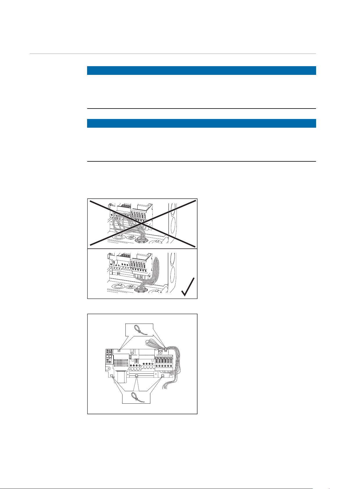
If AC cables are laid over the shaft of
the DC main switch or across the DC
main switch connection block, the
cables may be damaged when the inverter is pivoted or the inverter may
not be able to be pivoted.
Example: Fronius Primo 3.8–8.2
IMPORTANT! Do not lay AC cables
over the shaft of the DC main switch
or across the DC main switch connection block!
If excessively long AC or DC cables are
laid in loops in the connection area, fix
the cables to the designated eyelets at
the top and bottom of the connection
block using cable ties.
28
Example: AC cables (Fronius Primo 3.8–8.2)
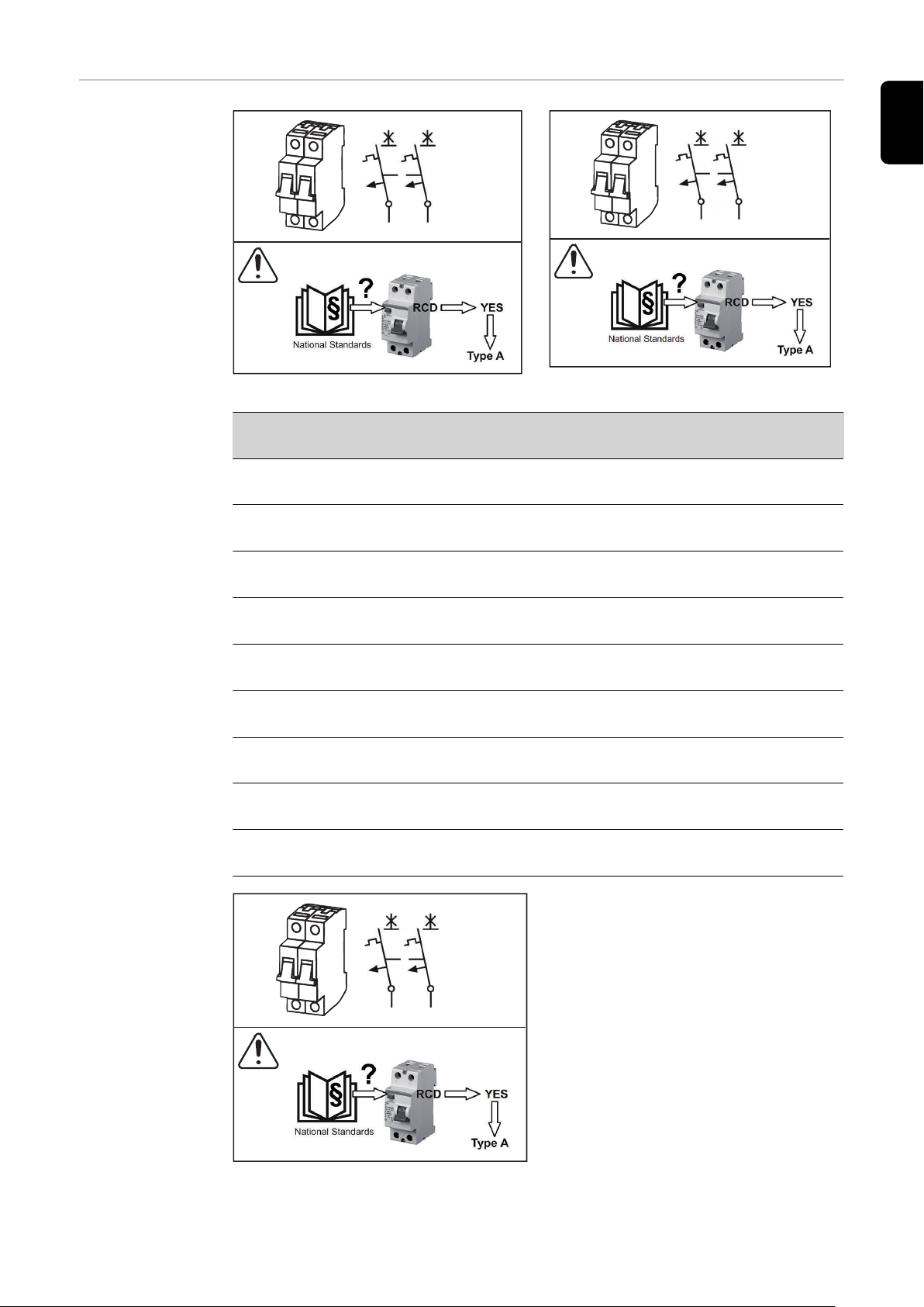
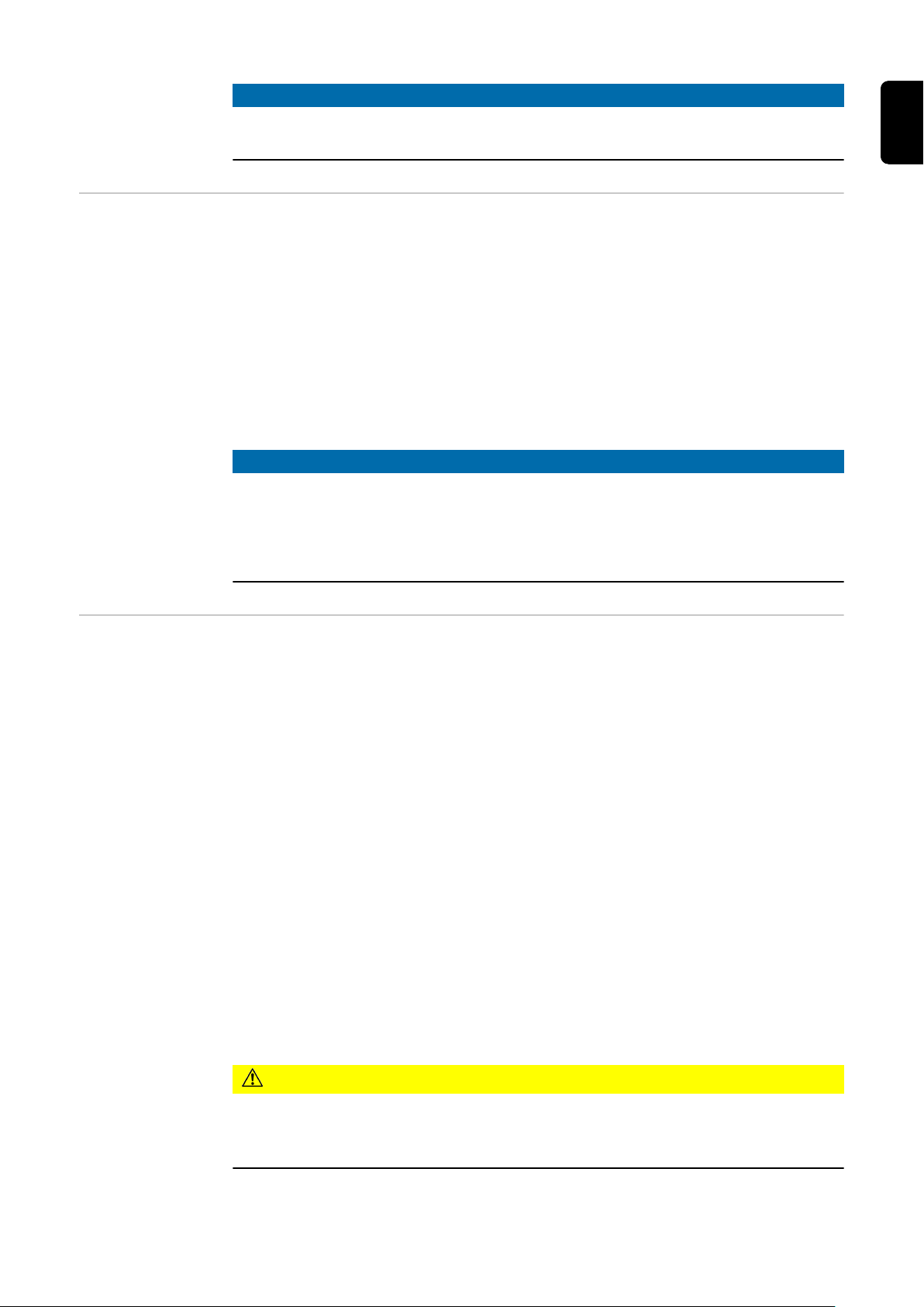
Maximum AC
AC ~
max. 63 A
2 4
31
I∆N ≥ 100 mA
max. 100 A
AC ~
2 4
31
AC ~
max. 63 A
2 4
31
I∆N ≥ 100 mA
fuse protection
EN-US
Fronius 3.8–8.2
Fronius 10.0–15.0
Inverter Phases Max. output Max. fuse protec-
tion
Fronius Primo 3.8-1
1 / 2 3800 W 63 A
208-240
Fronius Primo 5.0-1
1 / 2 5000 W 63 A
208-240
Fronius Primo 6.0-1
1 / 2 6000 W 63 A
208-240
Fronius Primo 7.6-1
1 / 2 7600 W 63 A
208-240
Fronius Primo 8.2-1
1 / 2 8200 W 63 A
208-240
Fronius Primo 10.0-1
1 / 2 10,000 W 100 A
208-240
Fronius Primo 11.4-1
1 / 2 11,400 W 100 A
208-240
Fronius Primo 12.5-1
1 / 2 12,500 W 100 A
208-240
Fronius Primo 15.0-1
208-240
1 / 2 15,000 W 100 A
29

NOTE!
A residual current circuit breaker for the AC connecting cable may be required
depending on local regulations, the power supply company as well as other conditions.
A type A residual current circuit breaker with a trip current of at least 100 mA is
generally sufficient in this case. Nevertheless, false alarms can be triggered for
the type A residual current circuit breaker in individual cases and depending on
local conditions.
For this reason, Fronius recommends that you use a residual current circuit
breaker suitable for a frequency converter.
Additional external AC and/or
DC disconnect
Depending on the installation, an additional external AC and/or DC disconnect
may be required if the inverter is installed in a location not easily accessible to
utility or fire personnel. Contact your local authorities for additional information.
30

DC=
31

32

Notes on DC Connection
EN-US
Safety
WARNING!
Danger from grid voltage and DC voltage from solar modules that are exposed
to light.
An electric shock can be fatal.
Prior to any connection work, ensure that the inverter is de-energized on the
▶
AC side and the DC side.
The DC main switch is used only to switch off power to the power stage set.
▶
When the DC main switch is turned off, the connection area is still energized.
Maintenance and service work on the inverter power stage set should only be
▶
carried out by Fronius-trained service technicians.
All maintenance and service work should only be carried out when the invert-
▶
er and the mounting bracket have been disconnected from each other.
The inverter must only be disconnected from the mounting bracket after be-
▶
ing disconnected from the mains power.
Only an authorized electrician is permitted to connect this inverter to the
▶
public grid.
WARNING!
Inadequately sized electrical components can cause serious injury and damage
to property.
An electric shock can be fatal.
All electrical connections must be established in accordance with the nation-
▶
al standard (e.g., for the US National Electrical Code, ANSI/NFPA 70) and
any other regulations applicable to the installation site.
Installations in Canada must be carried out in accordance with applicable
▶
Canadian standards.
Use min. 167°F (75°C) copper wire for all grounding wires (see NEC table
▶
250.122).
Use for all AC/DC wires, min. 167°F (75°C).
▶
Voltage drop and other considerations, such as improving power quality, may
▶
mean larger cable cross sections need to be used.
Use only solid or stranded wire. Do not use fine stranded wire.
▶
WARNING!
Danger from work that is not carried out properly
This can result in severe personal injury and damage to property.
The surge protection device should only be installed and connected by li-
▶
censed electricians.
Observe the safety rules!
▶
Prior to any installation and connection work, ensure that the inverter is de-
▶
energized on the AC side and the DC side.
33

WARNING!
Danger due to incorrect or insufficient solar module grounding.
An electric shock can be fatal.
The inverter is designed for solar module grounding at the negative pole as
▶
standard. Solar module grounding is carried out via a GFDI fuse in the inverter.
When operating ungrounded solar modules, remove the GFDI fuse before
▶
starting operation and adjust the inverter grounding settings accordingly.
When operating solar modules with grounding at the positive pole, the solar
▶
modules are not grounded via the fuse in the inverter, but rather must be
grounded externally to the inverter.
CAUTION!
Danger due to improperly connected terminals.
This can result in thermal damage to the inverter, which can lead to fires.
When connecting the AC and DC cables, make sure that all terminals are
▶
tightened securely using the proper torque.
CAUTION!
Danger due to overload on the inverter.
The inverter may be damaged.
Only connect a maximum of 20 A to each DC terminal.
▶
Connect the DC+ and DC- cables to the correct DC+ and DC- terminals on
▶
the inverter.
Observe the maximum DC input voltage.
▶
NOTE!
Do not connect the ground to the negative DC line at any point!
This is already done within the inverter. If negative DC lines are connected to the
DC terminals or prior to this to the ground, this will circumvent the GFDI protection system, preventing your inverter from properly detecting a fault current. In
addition, turning the DC disconnector to the "OFF"/open circuit condition will
not disconnect the PV modules from ground, as it only disconnects the DC positive.
NOTE!
When connecting aluminum cables:
Follow all national and international guidelines regarding the connection of
▶
aluminum cables.
Follow the instructions of the cable manufacturer.
▶
Perform an annual check to ensure that the cables are firmly attached ac-
▶
cording to the proper torque.
NOTE!
When connecting DC cables, ensure the polarity is correct.
34
NOTE!
Form a min. 4 in. (100 mm) cable loop with all cables.
NOTE!
To ground solar module frames or mounts, you must observe both the relevant
instructions from the solar module manufacturer and national guidelines.
EN-US
General Information about Solar
Modules
String Fuses Only valid for the device types with the "Ecofuse" option:
In order to select suitable solar modules and get the most efficient use out of
the inverter, please note the following points:
The open circuit voltage of the solar modules increases as the temperature
-
decreases (assuming constant irradiance).
Note the temperature coefficients in the solar module data sheet.
-
More exact data for sizing the solar modules can be obtained using calcula-
-
tion tools such as the Fronius Configuration Tool (available at http://
www.solarweb.com).
See NEC table 690.7 for the appropriate code-related voltage adjustment
-
factor for crystalline silicon modules, or use the manufacturer’s specified
voltage coefficient.
NOTE!
Before connecting solar modules, make sure that the voltage specified by the
manufacturer corresponds to the actual measured voltage.
Note the safety instructions and specifications of the solar module manufacturer
regarding solar module grounding.
The use of string fuses provides additional fuse protection for solar modules.
The maximum short circuit current ISC, the maximum module backfeed current
IR, and the specification of the maximum string fuse value in the module data
sheet of the respective solar module are decisive factors in the protection of the
solar module.
The maximum short circuit current ISC per terminal is 15 A.
The string fuse release current can be set to greater than 15 A if required.
However, a release current of 20 A must not be exceeded.
If the inverter is being operated with an external string collection box, the DC
connector kit 25 (item numbers 42,0201,4479 for DC+ and 42,0201,4480 for
DC-) must be used. In this case the solar modules are externally protected in the
string collection box and the metal bolts should be used in the inverter.
National regulations regarding fuse protection must be observed. The electrical
engineer carrying out the installation is responsible for the correct choice of
string fuses.
CAUTION!
Danger due to faulty fuses.
This can result in fire.
Only replace faulty fuses with new ones of the same rating.
▶
The inverter is delivered with metal bolts as standard.
35

Option DC SPD
DC+ 2.1
DC+ 1.1
DC+ 1.3
DC+ 1.2
DC+ 2.3
DC+ 2.2
DC- 1.2
DC- 1.1
DC- 1.3
DC- 2.1
DC- 2.2
DC- 2.3
Do not remove cover!
Each Terminal: I
max
= 15 A
Inverter DC
Connection
The inverter is designed exclusively to
be connected and used with nongrounded solar modules.
The solar modules cannot be grounded
at either the positive or negative pole.
IMPORTANT! Check the polarity and voltage of the solar module strings.
If DC cables are laid over the shaft of
the DC main switch, or across the DC
main switch connection block, they
could be damaged when the inverter
swivels in, or the inverter could be prevented from swiveling in.
Multi MPP
Tracker inverter
– Fronius Primo
3.0–8.2
36
IMPORTANT! Do not lay the DC cable
over the DC main switch or across the
DC main switch connection block.
Multi MPP Tracker inverters have two independent DC inputs (MPP Tracker).
These inputs can be connected to a number of different modules.
Each MPP Tracker has 2 DC+ terminals. There are a total of four DC- terminals.

Connecting 2–4 strings in Multi MPP Tracker mode:
Connect the strings separately to the
two MPP Tracker inputs (DC+1/DC+2).
The DC- terminals can be used as desired, since they are connected internally.
Set MPP TRACKER 2 to "ON" when
starting for the first time (also possible
in the basic menu subsequently).
Connecting two solar module fields to a Multi
MPP Tracker inverter
Single MPP Tracker mode on a Multi MPP Tracker inverter:
If the strings are connected with a
string collection box and only one collective line is used for connection to
the inverter, connection DC+1 (pin 2)
and DC+2 (pin 1) must be bridged.
The cable cross section of the DC connecting line and bridging must be the
same. Bridging the DC terminal is not
necessary because it is bridged internally.
EN-US
Connecting multiple combined solar module
fields to a line on a Multi MPP Tracker inverter
Set MPP TRACKER 2 to "OFF" when
starting for the first time (also possible
in the basic menu subsequently).
If the Multi MPP Tracker inverter is operated in Single MPP Tracker mode,
the currents of the connected DC lines
are distributed evenly across both inputs.
37

Single MPP Tracker mode with just one string on a Multi MPP Tracker inverter:
DC-1
PV 1PV 1
PV 2
DC+1
DC-2
DC+2
MPP1: each Terminal
I
max
= 15 A
1
DC
+1 DC+2
DC-1 DC-2
2
1 2 3 4 1 2
3 1 2
4
If only one string is used for connection to the inverter, connection DC+1
(pin 2) and DC+2 (pin 1) must be
bridged.
The cable cross section of the DC connecting line and bridging must be the
same. Bridging the DC terminal is not
necessary because it is bridged internally.
Set MPP TRACKER 2 to "OFF" when
starting for the first time (also possible
in the basic menu subsequently).
Multi MPP
Tracker Inverter
– Fronius Primo
10.0–15.0
Connecting just one string to a Multi MPP Tracker inverter
If the Multi MPP Tracker inverter is operated in Single MPP Tracker mode,
the currents of the connected DC lines
are distributed evenly across both inputs.
Multi MPP Tracker inverters have 2 independent DC inputs (MPP Tracker). These
inputs can be connected to a number of different modules.
MPP Tracker 1 has 4 DC+ terminals.
MPP Tracker 2 has 2 DC+ terminals.
There are a total of 6 DC- terminals.
Connecting 2-6 strings in Multi MPP Tracker mode:
Connect the strings separately to the
two MPP Tracker inputs (DC+1/DC+2).
The DC- terminals can be used as desired, since they are connected internally.
Set MPP TRACKER 2 to "ON" when
starting for the first time (also possible
in the basic menu subsequently).
38
Connecting two solar module fields to a Multi
MPP Tracker inverter

Notes on Laying Data Communication Cables
EN-US
Laying Data
Communication
Cables
IMPORTANT! The inverter must not be operated with one option card and 2
knocked-out option card slots.
In this case Fronius provides an appropriate dummy cover as an accessory:
42,0405,2020 ... for Fronius Primo 3.8–8.2
42,0405,2094 ... for Fronius Primo 10.0–15.0
IMPORTANT! If data communication cables are wired into the inverter, observe
the following points:
Provide separate conduits for data communication cables
-
Lay data communication cables in the supplied protective hose
-
Knock out the appropriate opening
-
Cleanly deburr the knocked-out opening
-
Fronius Primo 3.9–8.2 only:
-
Insert the supplied cable gland into the opening (if both openings are
knocked out, an additional cable gland 42,0405,2019 is required)
Clip the inverter onto the wall bracket
-
Guide the data communication cables through the cable glands from behind
-
When pivoting the inverter, ensure that the cables are not trapped, kinked, or
-
damaged in any other way. Do not loop the data communication cables.
Lay the data communication cables in the data communication area of the
-
inverter and connect to the Solar Net "IN" and "OUT" connections.
Plug the termination plugs into the remaining Solar Net connections.
39

Notes on Clipping the Inverter into the Wall
ON
OFF
Lock
22.1 lbf.in / 2.5 Nm
Bracket
Clipping the Inverter onto the
Wall Bracket
The side areas of the housing cover are
designed to function as carrying grips
and/or handles.
NOTE!
The inverter is fitted with a lock for
safety reasons, which allows the inverter to be pivoted in the wall bracket
only when the DC main switch is off.
Only clip on and pivot the inverter
▶
in the wall bracket when the DC
main switch is off.
Do not use excessive force to clip
▶
on the inverter and pivot it.
The fixing screws in the data communication area of the inverter are used to fix
the inverter to the wall bracket. Fixing screws must be properly tightened to ensure correct contact between the inverter and the wall bracket.
CAUTION!
Danger of damaging the inverter due to improperly tightened fixing screws.
Improperly tightened fixing screws may cause arcs to occur when the inverter is
operated, which may lead to fire. Always tighten the fixing screws with the specified torque.
40

Notes on Anti-theft device
2
2
1
TX25
2
22.1 lbf.in
2.5 Nm
3
1
TX25
EN-US
Anti-Theft
Device
Fronius Primo 3.8–8.2 only
An optional anti-theft device is included in the scope of delivery.
If required, the anti-theft device is installed before the inverter is screwed to the
wall bracket.
To ensure that the fixing screws cannot fall out in the inverter's data communications area, these are fitted with a screw release.
To remove the fixing screw from the inverter
Push the fixing screw upwards from the other side e.g. using needle-nose pli-
-
ers
Undo the fixing screw
-
Mounting the Anti-Theft Device
IMPORTANT! Please refer to the instructions for attaching the inverter to the
wall bracket.
Swing the inverter out
1
Push the fixing screw upwards
2
from the other side e.g. using
needle-nose pliers
Undo the fixing screw
3
Insert the fixing screw into the
4
anti-theft device
Insert the anti-theft device plus
5
fixing screw into the inverter
Swing the inverter in
6
Tighten both fixing screws to the
7
specified torque
41

2
2
1
max 0.28 in. (7 mm)
Fit the padlock to the anti-theft
8
device
42

Notes on Software Updates
USB
+
3
5
4
4
1
2
2
EN-US
Notes on Software Updates
Insert the USB stick in the inverter
1
data communication area
Access the Setup menu
2
Select the "USB" menu item
3
Select "Update Software"
4
Install the update
5
43

USB Stick as a Data Logger and for Updating Inverter Software
USB Flash Drive
as a Data Logger
Data on the USB
stick
A USB flash drive connected to the USB A socket can act as a data logger for an
inverter.
The logging data that is saved on the USB flash drive can be viewed directly in
third-party applications (e.g., Microsoft® Excel) at any time via the included CSV
file.
Older Excel versions (up to Excel 2007) have a row limit of 65536.
If the USB stick is used as a datalogger, three files are automatically created:
FRONIUS.sys system file:
-
This file saves information from the inverter that is irrelevant to the customer. The file must not be deleted individually. Only delete all files together
(sys, fld, csv).
DALO.fld log file:
-
Log file for reading out data in Fronius Solar.access.
You can find additional information on the Fronius Solar.access Software in
the "DATCOM Detail" operating instructions at http://www.fronius.com
DATA.csv log file:
-
A log file for reading out data in a spreadsheet program (e.g., Microsoft® Excel)
Data structure on the USB stick
(1) USB root directory
(2) Fronius inverter (Fronius Galvo,
Fronius Symo, Fronius Primo, or
Fronius Eco)
(3) Inverter number – can be set in
the setup menu under DATCOM
If multiple inverters exist with the
same inverter number, the three files
are saved in the same folder. A number
is appended to the file name (e.g.,
DALO_02.fld)
44

Structure of the CSV file:
(1) (2) (3)
(4)
(5) (6) (7)
(8)
(9)
(1) ID
(2) Inverter no.
(3) Inverter type (DATCOM code)
(4) Logging interval in seconds
(5) Energy in watt-seconds with reference to the logging interval
(6) Inductive reactive power
(7) Capacitive reactive power
(8) Averages over the logging interval (AC voltage, AC current, DC voltage,
DC current)
(9) Additional information
EN-US
Data Amount
and Memory Ca-
One USB thumb drive with a memory capacity of 1 GB, for example, can record
logging data at a logging interval of 5 minutes for approx. 7 years.
pacity
CSV file
CSV files can store only 65,535 rows (data records) (up to Microsoft® Excel version 2007, afterwards there is no limit).
At a logging interval of 5 minutes, the 65,535 rows are written within approx. 7
months (CSV data size of approx. 8 MB).
To avoid a loss of data, the CSV file should be backed up to a PC within these
7 months and deleted from the USB thumb drive. If the logging interval is set
longer, this time frame is extended accordingly.
FLD file
The FLD file should not be larger than 16 MB. At a logging interval of 5 minutes,
this corresponds to a storage duration of approx. 6 years.
If the file exceeds this 16 MB limit, it should be backed up to a PC, and all data
should be deleted from the USB thumb drive.
After you have backed up the data and removed it from the USB thumb drive,
the thumb drive should be immediately reinserted so that it can record logging
data; no further steps are required.
Notice! A full USB thumb drive can lead to loss of data or overwriting of data.
When inserting the USB thumb drive, make sure that it has a sufficient memory
capacity.
45

NOTE!
Risk from a full USB thumb drive.
This can result in the loss of data or data being overwritten.
When inserting the USB thumb drive, make sure that it has a sufficient
▶
memory capacity.
Buffer Memory If the USB flash drive is removed (e.g., to back up data), the logging data is writ-
ten to a buffer memory in the inverter.
As soon as the USB flash drive is reinserted, the data is automatically transferred
from the buffer memory to the USB flash drive.
The buffer memory can store a maximum of 6 logging points. Data is logged only
during inverter operation (power greater than 0 W). The logging interval is set to
30 minutes. This results in a time span of 3 hours for recording data in the buffer
memory.
When the buffer memory is full, the oldest data in the buffer memory is written
over with the new data.
IMPORTANT! The buffer memory requires a constant power supply.
If there is an AC power outage during operation, all data in the buffer memory is
lost. The automatic night switch-off must be deactivated so that data is not lost
at night (set “Night Mode” setup parameter to ON – see the Operating Instructions for Datamanager 2.0 and the sections “Setting and Displaying Menu Items,”
“Displaying and Setting Parameters in the ‘DATcom’ Menu Item”).
For Fronius Eco or Fronius Symo 15.0-3 208, the buffer memory also works with
pure DC voltage.
Suitable USB
Thumb Drives
Due to the number of USB thumb drives on the market, we cannot guarantee
that every USB thumb drive will be recognized by the inverter.
Fronius recommends using only certified, industrial USB thumb drives (look for
the USB-IF logo).
The inverter supports USB thumb drives using the following file systems:
FAT12
-
FAT16
-
FAT32
-
Fronius recommends that the USB thumb drive only be used for recording logging data or for updating the inverter software. USB thumb drives should not
contain any other data.
46

USB symbol on the inverter display, e.g., in the 'NOW' display mode:
AC Output Power
NOW
When the inverter recognizes a USB
thumb drive, the USB symbol will appear at the top right of the display.
When inserting the USB thumb drive,
make sure that the USB symbol is displayed (it may also be flashing).
Notice! Please be aware that in outdoor applications the USB thumb drive may
only function in a limited temperature range.
Make sure, for example, that the USB thumb drive will also function at low temperatures for outdoor applications.
EN-US
USB Stick for
Updating Inverter Software
Removing the
USB Stick
The USB stick can be used to help end customers update inverter software via
the USB menu item in the SETUP menu item: the update file is first saved on the
USB stick and then transferred to the inverter. The update file must be saved in
the USB stick root directory.
Safety information for removing a USB stick
IMPORTANT! To prevent a loss of
data, the connected USB stick
should only be removed under the
following conditions:
via the SETUP and "Safely re-
-
move USB / hardware" menu
items
when the "Data Transfer" LED is
-
no longer flashing or illuminated.
47

Notes on Maintenance
Maintenance Notice! For a horizontal installation position and installation outside: perform an
annual check to ensure that all screw connections are tightly fastened.
Maintenance and service work may only be carried out by Fronius-trained service
technicians.
Cleaning Wipe the inverter, if necessary, with a damp cloth.
Do not use cleaning agents, scouring agents, solvents, or similar products to
clean the inverter.
48

Serial Number Sticker for Customer Use
EN-US
Serial number
sticker for customer use
The inverter's serial number can be
found on the rating plate on the bottom of the inverter.
The installation position may make it
difficult to access or read the serial
number, e.g. if the inverter has been installed in a dark or shaded area.
Two serial number stickers are enclosed with the Installation Instructions for the inverter:
* 57 x 20 mm
** 67 x 20 mm
The customer can attach these stickers themselves in a clearly visible
place, e.g. on the front of the inverter
or on the Operating Instructions.
Application example:
Serial number stickers on the Operating Instructions or on the front of the
inverter
Australia only:
Affix DRM Australia sticker in
Datamanager area.
49

50

EN-US
51

-
-
 Loading...