

Page 1

/ Battery Charging Systems / Welding Technology / Solar Electronics
EN-US
Fronius Personal Display DL
Operating Instructions
System monitoring
42,0410,1818 003-17042012
Page 2

0
Page 3

Dear reader,
Introduction Thank you for the trust you have placed in our company and congratulations on buying this
high-quality Fronius product. These instructions will help you familiarize yourself with the
product. Reading the instructions carefully will enable you to learn about the many different
features it has to offer. This will allow you to make full use of its advantages.
Please also note the safety rules to ensure greater safety when using the product. Careful
handling of the product will repay you with years of safe and reliable operation. These are
essential prerequisites for excellent results.
EN-US
1
Page 4

2
Page 5

Contents
General ...................................................................................................................................................... 5
Device concept ..................................................................................................................................... 5
Information on radio certification........................................................................................................... 5
System requirements ............................................................................................................................ 5
Utilization in accordance with "intended purpose" ................................................................................ 6
Functional principle ............................................................................................................................... 6
Included system components ............................................................................................................... 7
Operating controls and connections .......................................................................................................... 8
General ................................................................................................................................................. 8
Operating controls and connections ..................................................................................................... 8
Display .................................................................................................................................................. 9
Before installation ...................................................................................................................................... 11
Safety.................................................................................................................................................... 11
Installation specifications ...................................................................................................................... 11
Inserting a Fronius Display Card or Fronius Com Card into the inverter .............................................. 11
Attaching the antenna to the wall and connecting to the inverter ......................................................... 12
Installing and connecting the antenna to the inverter ...........................................................................13
Integrating the Fronius Personal Display DL Box into Fronius Solar Net ............................................. 14
Installing / Setting up the Fronius Personal Display DL ........................................................................ 15
Commissioning .......................................................................................................................................... 16
Inverter configuration ............................................................................................................................ 16
Start-up operation ................................................................................................................................. 16
Establishing power supply - inserting batteries..................................................................................... 16
Establishing power supply - connecting power supply unit................................................................... 17
Start-up phase - setting the date and time............................................................................................ 17
Connecting to the Fronius Personal Display DL Box or inverter ........................................................... 19
Operating concept...................................................................................................................................... 21
General ................................................................................................................................................ 21
Display modes ...................................................................................................................................... 21
Activating display illumination ............................................................................................................... 21
Display sleep mode............................................................................................................................... 21
Automatic switching to the ‘Now’ display mode .................................................................................... 22
Operating status LED............................................................................................................................ 22
Operating scheme - the display ................................................................................................................. 23
Selecting display modes ....................................................................................................................... 23
Displaying power data for the total system (ALL) or individual inverters (IGxx).................................... 23
Display values............................................................................................................................................ 25
Display values for an individual inverter in the 'Now' display mode ...................................................... 25
Display values for a total system in the 'Now' display mode ................................................................. 26
Display values for individual inverters in the 'Day / Year / Total' display modes................................... 26
Display values for a total system in the 'Day / Year / Total' display modes .......................................... 28
The Setup Menu ........................................................................................................................................ 29
General ................................................................................................................................................. 29
Accessing the Setup menu ................................................................................................................... 29
Setting Menu Items - General ............................................................................................................... 30
Menu Items in the Setup Menu .................................................................................................................. 31
Sequence of menu items ...................................................................................................................... 31
OFFSET................................................................................................................................................ 31
CASH .................................................................................................................................................... 31
SLEEP LCD .......................................................................................................................................... 31
CONTRAST .......................................................................................................................................... 32
LIGHT LCD ........................................................................................................................................... 32
CHECK RF............................................................................................................................................ 32
ADD IG.................................................................................................................................................. 33
DEL IG .................................................................................................................................................. 33
VERSION.............................................................................................................................................. 33
TIME ..................................................................................................................................................... 34
LOG ...................................................................................................................................................... 34
MENU MODE........................................................................................................................................ 34
Fronius Personal Display DL as a datalogger............................................................................................ 35
EN-US
3
Page 6

General ................................................................................................................................................. 35
Memory capacity................................................................................................................................... 35
Overwriting data when memory is full ................................................................................................... 35
Processing recorded data ..................................................................................................................... 36
Charging batteries...................................................................................................................................... 37
Safety.................................................................................................................................................... 37
Checking the battery charge status ...................................................................................................... 37
Charging batteries................................................................................................................................. 38
Battery disposal .................................................................................................................................... 38
Troubleshooting ......................................................................................................................................... 39
General ................................................................................................................................................. 39
Troubleshooting .................................................................................................................................... 39
Resetting the Fronius Personal Display Card in the inverter ................................................................ 41
Technical data............................................................................................................................................ 42
Fronius Personal Display DL ................................................................................................................ 42
Fronius Personal Display Card ............................................................................................................. 42
Fronius Personal Display DL Box ......................................................................................................... 42
4
Page 7

General
Device concept The Fronius Personal Display DL can be used to display real-time power data from one or
more inverters from any location within range of the device.
The Fronius Personal Display DL also functions as a datalogger.
The recorded data are then analyzed using Fronius Solar.access.
The Fronius Personal Display DL can show power data from up to 15 Fronius inverters.
The various display modes can show power data for the entire system or for each individual
inverter.
The Fronius Personal Display DL is powered via a battery or the power supply included
with the device.
EN-US
Information on radio certification
System requirements
The Fronius Personal Display DL is fitted with an radio module.
In the USA radio modules are subject to FCC requirements::
This device complies with Part 15 of the FCC Rules. Operation is subject to
the following conditions:
(1) This device may not cause harmful interference, and
(2) This device must accept any interference received, including interference that may cause undesired operation.
FCC ID: QKWFRF905
Changes or modifications of the radio module not expressly approved are not allowed and
will void the user’s authority to operate the equipment.
The Fronius Personal Display DL can be used with up to 15 of the following Fronius inverters:
- Fronius IG
- Fronius IG Plus / Fronius IG Plus V
- Fronius CL
Different inverter types can also be combined.
The following are required to send data to the Fronius Personal Display DL
a) a Fronius Display Card with a radio antenna for each inverter,
or
b) a Fronius Personal Display DL Box
and
a Fronius Com Card for each inverter.
The Fronius Personal Display DL can be used with a Fronius IG inverter serial number
17xxxxxx and higher.
The datalogging function is not available when using a Fronius Personal Display DL Card
with a Fronius IG inverter.
A Fronius Personal Display DL Box must be connected to a Fronius IG inverter to enable
the datalogging function.
5
Page 8

When the Fronius Personal Display DL is configured with the Fronius Personal Display DL
IN
*
OUT
...
Fronius IG Plus 1 Fronius IG Plus 2 Fronius IG Plus 15
Com Card
IN
OUT
Com Card
IN
OUT
Com Card
Fronius Personal
Display DL Box
IN
Card, the Fronius Personal Display DL does not log data if another data logger is present
in the system (e.g., Fronius Datalogger or Fronius Datalogger Web).
No other data logger may be present in the system when using the Fronius Personal Display DL Box.
In addition to inverters, the Fronius Personal Display DL can also be operated in conjunction with a Fronius Personal Display DL Box with the following DATCOM components:
- 1 x Fronius Power Control Box
- 1 or more Fronius String Control(s)
- 1 x Fronius Sensor Card / Box (assigned no. 1)
- 1 x Fronius Public Display (assigned no. 1)
Utilization in accordance with
"intended purpose"
Functional principle
The Fronius Personal Display DL is designed only for use in photovoltaic systems with a
Fronius inverter.
Any other purpose does not constitute intended use.
The manufacturer shall not be liable for any damage resulting from such improper use. Intended use also includes following all information from the operating instructions.
Example: Fronius IG with Fronius Personal Display Card
6
Example: Fronius IG Plus with Fronius Com Card and Fronius Personal Display DL Box (* = termination plug)
Page 9

Included system
USB
2 m
components
EN-US
Fronius Personal Display DL included components Fronius Personal Display Card included components
Fronius Personal Display DL Box included components
7
Page 10

Operating controls and connections
General
Operating controls and connections
NOTE! Because of firmware updates, certain functions may be available for your
device but not described in these operating instructions or vice versa. In addition,
individual figures may also differ slightly from the operating elements of your device. However, the function of these operating elements is identical.
The Fronius Personal Display DL can be used to display power data for the entire system
as well as for each individual inverter. The menu control is mostly identical to that of the
inverter.
(1)
(2)
(3)
(4)(5)(6)(7)(8)
Item Description
(1) Display
for displaying values, settings and menus
(2) Operating status LED
for displaying the operating status
(3) 'Enter' key
for confirming a selection
(4) Battery compartment with cover
for battery insertion to supply power
(5) 'Menu/Esc' key
for switching to the menu level
for exiting the Setup menu
(6) 'Down/Right' key
depending on the selection:
for navigating down
or to the right
(7) 'Left/Up' key
depending on the selection:
for navigating left
or up
(8) USB connection (Micro-USB)
8
Page 11

Display
(11) (10)
(3) (4) (5)
(6)
(7)
(13)
(12)
(9) (8)
(1) (2)
EN-US
Item Function
(1) Icons for the 'Now' display mode
(2) Icons for the 'Day' display mode
(3) Icons for the 'Year' display mode
(4) Icons for the 'Total' display mode
(5) Icons for the 'Setup' display mode
(6) Icons for operating conditions
The value shown represents the maximum value within the period of
observation (depending on which display mode is selected).
The value shown represents the minimum value within the period of
observation (depending on which display mode is selected).
IMPORTANT The min. and max. values may not correspond to the
absolute extreme values, as the measured data are recorded at two
second intervals.
... appears with data readings that are directly related to the solar
modules
... appears with AC data readings that are directly related to the grid
... appears with data readings that are directly related to the inverter
(7) Area for display unit
for displaying the applicable measuring unit
(8) Icon for the 'Enter' key
(9) Icons for the 'Menu/Esc' key
(10) Icons for the 'Down/Right' key
(11) Icons for the 'Left/Up' key
9
Page 12

Item Function
(12) Area for display value
for displaying the value
(13) Segment bars
display the current charge status of the batteries (100 - 20%)
The bars begin to flash when the charge status approaches 0.
IMPORTANT When the batteries discharge further, the Fronius Personal Display DL switches to Sleep mode and discontinues wireless traffic. No information is shown on the display in Sleep mode.
'LOW BATT' appears on the display after any key is pressed.
Recharge batteries by plugging in the power supply.
10
Page 13

Before installation
EN-US
Safety
Installation specifications
WARNING! Operating the device incorrectly can cause serious injury and dam-
age. Do not use the functions described until you have thoroughly read and understood the following documents:
- these operating instructions
- all operating instructions for system components, especially the safety rules
WARNING! An electric shock can be fatal. Danger from grid voltage and DC voltage from solar modules.
- The inverter connection area should only be opened by a licensed electrician
after being disconnected from the grid power.
- Plug-in cards should only be inserted after the inverter has been disconnected from the AC and DC sides.
- Please note the safety information in your inverter's operating instructions.
WARNING! Risk of injury and damage by overvoltage!
The Fronius Personal Display Card is not suitable for a grid voltage of 277 V AC.
Only operate the Fronius Personal Display Card with the grid voltage specified by
the manufacturer.
The Fronius Personal Display DL should only be used indoors due to its NEMA 1 degree
of protection.
The device should be protected against direct exposure to moisture.
Inserting a Fronius Display Card
or Fronius Com
Card into the inverter
The antenna can be set up and operated outdoors without limitation.
NOTE! Follow general ESD precautions when handling option cards.
Insert and secure a Fronius Display Card or Fronius Com Card as per the inverter's
1
operating instructions.
Follow all safety information.
NOTE! When inserting the Fronius Display Card into the Fronius IG, the plug-in
card
- should only be inserted into slots labeled 'Option 1' or 'Option 2'
- should not be inserted under any circumstances into the slot on the far left
labeled 'ENS'
11
Page 14

Attaching the an-
1
1
tenna to the wall
and connecting to
the inverter
The antenna included with the Fronius Personal Display Card comes with a 2 m long connection cable. If the inverter is located within a room shielded from radio waves, it is possible to install the antenna outside of this area.
A cable extension is available from Fronius for Fronius CL inverters.
Fronius Personal Display DL
+
Fronius Personal Display Card
+
Fronius IG / Fronius IG Plus / Fronius CL inverters
NOTE! For systems with several inverters, antennas must be at least 19.7 in. (0,5
m) apart so that communication with the Fronius Personal Display DL is not disrupted. For an optimal range, we recommend a distance of 39.4 in. (1 m).
IMPORTANT The mounting bracket is part of the antenna. Only fit the antenna to the
mounting bracket supplied with the antenna.
2
Attaching the antenna to the wall Connecting the antenna cable to the inverter (e.g., to
the Fronius IG)
12
Page 15

Installing and
1
connecting the
antenna to the inverter
The following steps only apply to the following system configurations:
Fronius Personal Display DL
+
Fronius Personal Display Card
+
Fronius IG inverter
NOTE! For systems with several inverters, antennas must be at least 19.7 in. (0.5
m) apart so that communication with the Fronius Personal Display DL is not disrupted. For an optimal range, we recommend a distance of 39.4 in. (1 m) .
IMPORTANT The mounting bracket is part of the antenna. Only fit the antenna to the
mounting bracket supplied with the antenna.
Use the previously removed original housing screw to screw the antenna mounting
bracket onto the housing.
EN-US
1
2
3
5
Installing and connecting the antenna to the inverter
4
13
Page 16

Integrating the
...
1
2
3
4
6
5
7
(1)
(2)
(3)
(4)
(5)
(6)
(7) (7)
(4) (4)
(7)
IN
IN
IN
IN
OUT
OUT OUT
Fronius Personal
Display DL Box
into Fronius Solar
Net
The following steps only apply to the following system configurations:
- Fronius inverter with Fronius Com Card
- 1 Fronius Personal Display DL Box
1
(1) Inverter 1 (e.g., Fronius IG Plus)
(2) Inverter 2 (e.g., Fronius IG Plus)
(3) Inverter n (max. 15, e.g., Fronius IG Plus)
(4) Fronius Com Card
(5) Fronius Personal Display DL Box (corresponds to the functionality of a DATCOM
'IN' connection or termination plug)
(6) Termination plug (included with the Fronius Personal Display DL Box)
(7) CAT-5 cable (Solar Net cable)
14
Page 17

Installing / Setting
2
1
3
up the Fronius
Personal Display
DL
Using the included wall mounting device, the personal display can be
- installed on the wall in any room
or
- used as a tabletop device by turning the wall mounting device 90°
Wall installation:
EN-US
1
Tabletop device:
1
1
2
2
15
Page 18
Commissioning
1
Inverter configuration
Start-up operation
Establishing power supply - inserting batteries
The Fronius Personal Display DL can show power data from up to 15 Fronius inverters.
Therefore, each inverter must be assigned a unique address in order for the Fronius Personal Display DL to be able to distinguish between individual inverters. This address must
be in the form of a number from 01 - 15.
Set the inverter address as per the inverter's operating instructions, section "The setup
menu," "IG-Nr." menu item.
The start-up operation for the Fronius Personal Display DL includes the following sections:
a) Establishing the power supply
- Inserting the batteries
or
- Connecting the power supply unit
b) Connecting to the Fronius Personal Display DL Box or inverter
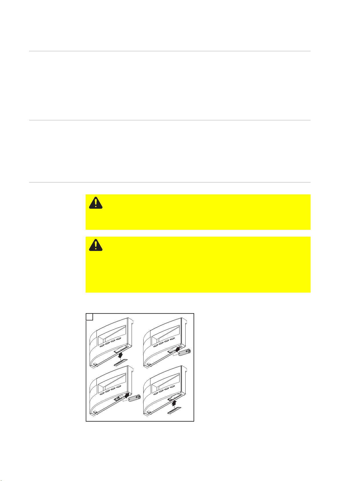
CAUTION! Using the wrong battery types can cause damage.
The Fronius Personal Display DL requires the following battery type for operation:
- NiMH batteries
- 1.2 V
- Size AA / LR6
CAUTION! Damaged, unequally charged or deeply discharged batteries may
cause damage.
- Only insert 2 fully charged batteries of the same type
- Only insert batteries with the same state of charge
(e.g., do not insert a half charged battery with a fully charged battery)
- Check batteries for damage before insertion
(e.g., acid leaks)
do not use damaged batteries.
The batteries delivered in the original packaging are already charged.
Make sure that batteries are inserted correctly.
1
3
2
4
After the batteries are inserted, the display runs through the start-up phase for setting the
time and date.
Afterwards, you can establish the connection to the inverters.
16
Page 19

Establishing power supply - connecting power
supply unit
The Fronius Personal Display DL can also be operated using a regular wall socket instead
of the batteries.
- Leave the battery compartment empty
- Connect the power supply unit to the Fronius Personal Display DL
Connect an appropriate power adapter to the power supply unit
1
2
EN-US
Start-up phase setting the date
and time
1
3
2
After the power supply unit is connected, the display runs through the start-up phase for
setting the time and date.
Afterwards, you can establish the connection to the inverters.
All display elements light up for about two seconds after the power supply is established.
The Operating Status LED lights up green for about one second, then red.
The code for the region is displayed for
about two seconds.
17
Page 20

The sequence for entering the date is displayed, the first digit of the day flashes.
Date format: DD.MM.YYYY
IMPORTANT The date and time must be
set so that the Fronius Personal Display DL
can operate as a datalogger.
Use the 'Up' and 'Down' keys to select
1
a value for the first digit of the day
Press the 'Enter' key
2
The second digit of the day flashes.
Repeat steps 1 and 2 for the second di-
3
git of the day, for the month and for the
last digits of the year.
The sequence for entering the time is displayed, the first digit of the hour flashes.
Time format: HH:MM, 24 h
Use the 'Up' and 'Down' keys to select
4
a value for the first digit of the hour
Press the 'Enter' key
5
The second digit of the hour flashes.
Repeat steps 4 and 5 for the second di-
6
git of the hour and for the minutes.
The date and time are stored, 'TIME' is displayed.
The Fronius Personal Display DL is now
ready to establish the connection to the
Fronius Personal Display DL Box or to the
inverter.
If an entry is not made, the Fronius Personal Display DL automatically switches to
the menu item 'ADD IG' for establishing a
connection after two minutes.
This time can be shortened by selecting the
menu item 'ADD IG' using the 'Down' key.
18
Page 21

Connecting to the
Fronius Personal
Display DL Box or
inverter
'ADD IG' is displayed.
Press the 'Enter' key
1
Depending on the system configuration, the
device starts searching for an available
Fronius Personal Display DL Box or any
available inverters.
'WAIT' is displayed.
For a configuration with a Fronius Personal
Display DL Box, the Fronius Personal Display DL Box found is then displayed.
No additional Fronius Personal Display DL
Boxes can be entered since there is only
one in the system.
EN-US
For a configuration with Fronius Personal
Display Cards, the first inverter found is displayed (e.g., IG 01).
Press the 'Enter' key to save the Froni-
2
us Personal Display DL Box or inverter
in the system
IMPORTANT If you do not press the 'Enter'
key to confirm the Fronius Personal Display
DL Box or inverter found, then they will not
be saved in the system and will not transmit
any power data to the Fronius Personal
Display DL.
'ADD IG' is displayed.
Repeat steps 1 and 2 until all inverters
3
have been saved in the system
19
Page 22

When the device cannot find any more inverters, 'WAIT' remains on the display.
Press the 'Esc' key to stop the process.
4
The Fronius Personal Display DL is now ready to show all system power data.
20
Page 23

Operating concept
General Four display modes are available for power data on the Fronius Personal Display DL. The
Setup menu is used to configure the various parameters.
Because the Fronius Personal Display DL has an independent power supply, you can also
access power data after nightfall.
During the day, the Fronius Personal Display DL shows the 'Now' display mode by default.
The inverter disconnects from the public grid at nightfall and the Fronius Personal Display
DL switches to the 'Day' display mode.
Display modes The 'Now' display mode shows the total power data of all inverters in the system by default.
If the system has up to 15 inverters, then you can access the power data of each individual
inverter.
If the system only has one inverter, then the Fronius Personal Display DL menu control is
nearly identical to that of the inverter.
The following display modes are available for power data for a total system or for each individual inverter in the system:
EN-US
Activating display
illumination
'Now' display mode ...... Displays real-time values
'Day' display mode ...... Displays values for power fed into the grid during that day
'Year' display mode ...... Displays values for power fed into the grid during the
present calendar year (only available in combination with
the optional Fronius Datalogger or for system configurations with the Fronius Personal Display DL Box)
'Total' display mode ...... Displays values for power fed into the grid since your in-
verter first started operating
Press any key.
1
The display illumination is activated.
If no key is pressed for 10 seconds, the display illumination goes out (provided that the
display illumination is set to automatic in the Setup menu).
The Setup menu also offers a choice between a permanently lit or permanently dark
display.
Display sleep
mode
To save battery power, the display switches to sleep mode and the display goes out after
the time defined in the Setup menu expires.
You can also deactivate the sleep mode in the Setup menu.
21
Page 24

Automatic
switching to the
‘Now’ display
mode
If no key is pressed for 2 minutes, the Fronius Personal Display DL switches automatically
to the 'Now' display mode and the real-time output power for the entire system is displayed.
The display switches to the ‘Now’ display mode from anywhere within the display modes
or the Setup menu.
Operating status
LED
The operating status LED on the Fronius Personal Display DL always indicates the current
status of the selected inverter.
During normal operation in the 'ALL' menu, the operating status LED remains dark.
When a service message is triggered for an inverter in the system, the operating status
LED begins to flash.
LED Description
Lights up red Service message for an individual inverter
Flashes red In the 'ALL' menu:
a service message has been triggered for an inverter in the system
Lights up green Normal operation for the selected inverter
Off In the 'ALL' menu:
Normal system operation
For an individual inverter:
The inverter is inactive (e.g., at night)
For more detailed information about statuses and the meaning of the operating status LED,
please see the inverter's operating instructions.
22
Page 25

Operating scheme - the display
2
EN-US
Selecting display
modes
Press the ‘Menu’ key
1
'MENU ALL' is displayed.
Use the ‘left’ or ‘right’ keys to select
your preferred display mode:
Now - Day - Year - Total
Press the 'Enter' key
3
The selected display mode is shown, e.g.,
'Day' display mode.
Displaying power
data for the total
system (ALL) or
individual inverters (IGxx)
Pressing 'Enter' changes the navigation arrows:
Use the 'left' or 'right' keys to select an individual inverter in the system:
ALL - IG01 - IG02 - ... - IG15
Use the 'Up' and 'Down' keys to display the power data for an individual inverter:
[W] - [V] - [A] - ... - [A]
dc
ALL Total system
IGxx Individual inverter
(e.g., IG 01)
Press the 'Enter' key
1
23
Page 26

'ALL' is displayed, the navigation arrows
2
4
6
switch to 'left' and 'right.'
Use the ‘Left’ or ‘Right’ keys to select
the desired system inverter
Release the 'Left' or 'Right' keys
3
The display switches to the display of power data for the inverter currently selected.
Press the 'Enter' key to access additional power data for this inverter.
The navigation arrows switch to 'up' and
'down.'
Use the 'Up' and 'Down' keys to display
5
additional power data for the selected
inverter.
Press the 'Enter' key to access power
data for additional inverters.
The navigation arrows switch to 'left' and
'right.'
Use the ‘Left’ or ‘Right’ keys to select
7
additional system inverters
Press the 'Enter' key to access additio-
8
nal power data for this inverter.
Press both navigation keys simultaneously to switch back to the 'Now' display mode showing the power data for
the total system.
24
Page 27
Display values
EN-US
Display values for
an individual inverter in the 'Now'
display mode
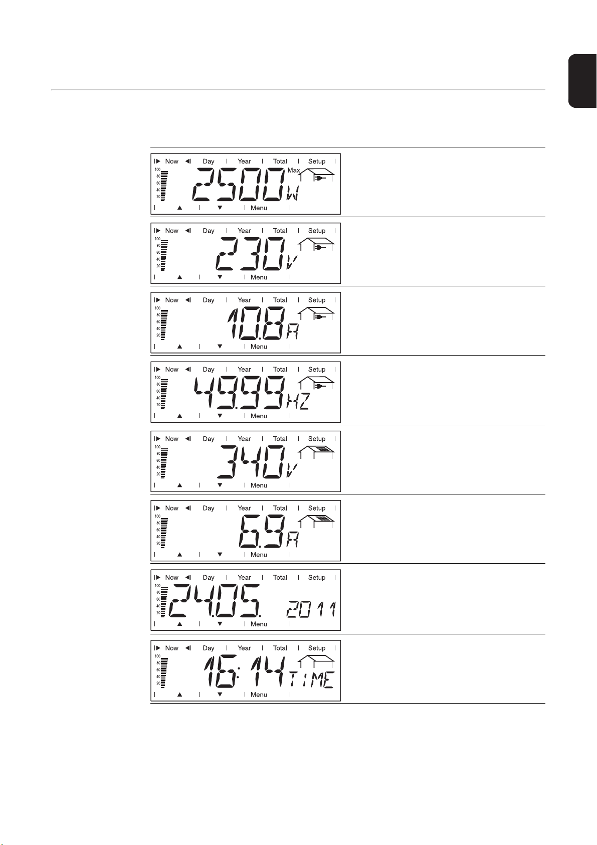
The Fronius Personal Display DL can show the following power data in the 'Now' display
mode for an individual inverter in the system:
Output power
Power (in Watts) currently being fed into
the grid
Grid voltage
External conductor voltage (Volts)
Output current
Current supplied to the grid at the particular moment (Amperes)
Grid frequency
(Hertz)
Solar module voltage
Voltage of the solar modules at the moment of data display (Volts)
Solar module current
Current supplied by solar modules at the
moment of data display (Amperes)
Date
When the date on the inverter or a data
communication component is changed,
this changes the date on all devices connected via Solar Net.
Time
When the time on the inverter or a data
communication component is changed,
this changes the time on all devices connected via Solar Net.
25
Page 28

Display values for
a total system in
the 'Now' display
mode
The Fronius Personal Display DL can show the following power data in the 'Now' display
mode for a total system:
Output power
Power (in Watts) currently being fed into
the grid
Date
When the date on the inverter or a data
communication component is changed,
this changes the date on all devices connected via Solar Net.
Time
When the time on the inverter or a data
communication component is changed,
this changes the time on all devices connected via Solar Net.
Display values for
individual inverters in the 'Day /
Year / Total' display modes
The Fronius Personal Display DL can show the following power data in the 'Day,' 'Year' and
'Total' display modes for an individual inverter in the system:
Output energy
Energy fed into the grid over the period of
time in question (kWh / MWh)
Due to the variety of different monitoring systems, there can be deviations between the
readings of other metering instruments and the readings from the inverter. For determining the energy supplied to the grid, only the readings of the calibrated meter supplied by
the electric utility company are relevant.
Yield
Amount of money earned during the period of time in question (currency can be selected in the Setup menu)
As was the case for the output energy, readings may differ from those of other instruments.
26
'The Setup menu' section describes how to set the currency and rate for the output energy. The factory setting depends on the respective country-specific setting.
Page 29

CO2 reduction
CO
emissions saved during the monitored period
2
(LB / T; T = tons)
The area for unit display switches between ‘LB’ or ‘T’ and ‘CO2.’
EN-US
The CO
meter gives an indication of CO2 emissions that would be released during the
2
generation of the same amount of electricity in a combustion power plant.
The factory setting is 1.3 lb / kWh.
Maximum output power
Highest output power of the inverter during observation period (Watts)
Maximum grid voltage
Highest reading of grid voltage (V) during
observation period
Minimum grid voltage
Lowest reading of grid voltage (V) during
observation period
Maximum solar module voltage
Highest reading of solar module voltage
(V) during observation period
Operating hours
Indicates how long the inverter has been
operating
(HH:MM)
Duration of operation is shown in hours and minutes up to 999 h and 59 min (display:
‘999:59’). After that only full hours are displayed.
Although the inverter does not operate during the night, all sensor data are recorded
around the clock.
27
Page 30

Display values for
a total system in
the 'Day / Year /
Total' display
modes
The Fronius Personal Display DL can show the following power data in the 'Day,' 'Year' and
'Total' display modes for a total system:
Output energy
Energy fed into the grid over the period of
time in question (kWh / MWh)
Due to the variety of different monitoring systems, there can be deviations between the
readings of other metering instruments and the readings from the inverter. For determining the energy supplied to the grid, only the readings of the calibrated meter supplied by
the electric utility company are relevant.
Yield
Amount of money earned during the period of time in question (currency can be selected in the Setup menu)
As was the case for the output energy, readings may differ from those of other instruments.
'The Setup menu' section describes how to set the currency and rate for the output energy. The factory setting depends on the respective country-specific setting.
CO
reduction
2
CO
emissions saved during the monitored period
2
(LB / T; T = tons)
The area for unit display switches between ‘LB’ or ‘T’ and ‘CO2.’
The CO
meter gives an indication of CO2 emissions that would be released during the
2
generation of the same amount of electricity in a combustion power plant.
The factory setting is 1.3 lb / kWh.
28
Page 31

The Setup Menu
General The Setup menu is used to configure the personal display for operation.
IMPORTANT It does not give you access to inverter settings.
EN-US
Accessing the
Setup menu
Press the ‘Menu’ key
1
'MENU ALL' is displayed.
Use the ‘Left’ or ‘Right’ keys to select
2
'Setup'
Press the 'Enter' key
3
The Setup menu’s first menu item is shown.
Scroll through the individual menu
4
items using the ‘Up’ and ‘Down’ keys.
Press the 'Menu' key to exit the Setup
menu.
29
Page 32

Setting Menu
4
5
6
7
8
9
Items - General
Access the Setup menu
1
Use the "Up" or "Down" keys to select the desired menu item
2
Press the "Enter" key
3
The first digit of a value to be set flashes:
Use the "Up" and "Down" keys to select a value for the first digit
Press the "Enter" key
The second digit of the value flashes.
Repeat steps 4 and 5 until ...
the entire value flashes.
Press the "Enter" key
Repeat steps 4 - 6 for units or other
values to be set until the unit or value
flashes.
Press the "Enter" key to save and apply the changes.
Press the "Esc" key to not save the
changes.
The available settings are displayed:
Use the "Up" and "Down" keys to se-
4
lect the desired setting
Press the "Enter" key to save and ap-
5
ply the selection.
Press the "Esc" key to not save the
selection.
The currently selected menu item is displayed.
The currently selected menu item is displayed.
30
Page 33

Menu Items in the Setup Menu
EN-US
Sequence of
menu items
OFFSET
The menu items of the Setup menu are described in ascending order.
You can scroll through menu items by pressing the 'Up' key.
Correction value setting for the Total energy display
The correction value defined is added to
the power data sent by the inverters in the
'ALL TOTAL' display mode.
Unit MWh
Setting range + or - (sign) / 4-digit (correction value) / decimal point*
Factory setting 0
* Once you have entered the 4-digit correction value, the navigation arrows switch
from 'up' and 'down' to 'left' and 'right.'
Use the 'Left' and 'Right' keys to move the decimal point to the desired location and
press the 'Enter' key.
CASH
SLEEP LCD
Currency setting and rate for invoicing the
energy supplied
Unit -
Display range Currency / Charge rate/kWh
Factory setting EUR
Time value setting for the sleep mode
The display turns off after the time has expired to save battery power.
Unit Minutes
Setting range 1 / 5 / 10 / NEVER
Factory setting 1
1 / 5 / 10 If no key is pressed, the display turns off after 1, 5 or 10 minutes.
The display is re-activated by pressing any key.
NEVER The display does not turn off in sleep mode.
31
Page 34

CONTRAST
Contrast setting on LCD display
Unit -
Setting range 0 - 7
Factory setting 7
Since contrast depends on temperature, it may be necessary to adjust the "CONTRAST"
menu item when ambient conditions change.
LIGHT LCD
CHECK RF
Initial setting for display illumination.
Unit -
Setting range AUTO / ON / OFF
Factory setting AUTO
AUTO: The display illumination will stop 10 seconds after the last time
a key has been pressed.
ON: The display illumination will be permanently on.
OFF: The display illumination will be permanently off.
The 'ON' setting is identical to the 'AUTO' for battery operation to prevent premature battery
discharge.
Tests the wireless connection to the inverters.
32
Scroll through the available inverters using
the ‘Up’ and ‘Down’ keys.
Display range IG01, IG02 - max. IG15;
RF OK IGxx
or
NO RF IGxx
RF OK IGxx The wireless connection is functioning properly for the selected
inverter.
NO RF IGxx The wireless connection with the selected inverter has been in-
terrupted or the selected inverter is out of range.
See also "Troubleshooting."
Page 35

ADD IG
Add a new inverter to the system.
EN-US
See also "Start-up operation" - "Connecting to the inverter."
DEL IG
VERSION
Deleting inverters from the system
You can delete an inverter from the system so that its data are not displayed by the Fronius
Personal Display DL:
- Select the desired inverter using the ‘Up’ and ‘Down’ keys.
- Press the 'Enter' key to confirm the inverter to be deleted
The display flashes.
- Press the 'Esc' key to cancel the process
or
press the 'Enter' key to delete the inverter from the system
Accesses and updates information about
the Fronius Personal Display DL and associated plug-in card in the inverter.
Unit -
Display range DISPLAY / SW UPDATE / CARD IGxx
Factory setting -
DISPLAY Accesses the software version of the Fronius Personal Display
DL
SW UPDATE The personal display software can be updated if required.
CARD IGxx Accesses the software version of the Fronius Personal Display
Card in the inverter.
When you press the 'Enter' key, the Fronius Personal Display
DL connects to the selected inverter. You can press the 'Esc'
key to cancel the process.
33
Page 36

TIME
For setting the date and time
Date format DD.MM.YYYY
Time format HH:MM, 24 h
See also "Start-up operation" - "Start-up phase - setting the date and time."
LOG
MENU MODE
Resetting all saved data that have not yet
been transferred to the PC or laptop
(e.g., test data, set-up data, data without
date and time)
- For Fronius Personal Display DL Box: use menu item 'CHECK RF' to check if there is
a wireless connection to the box.
- Press the 'Enter' key
'DEL LOG' is displayed.
- Press the 'Enter' key
The display 'DEL LOG' flashes.
- Press the 'Esc' key: cancels the process
or
press the 'Enter' key: resets saved data
'WAIT' is displayed, the data are deleted.
The Fronius Personal Display DL switches to the start-up phase.
User-specific display data settings in the
Now, Day, Year and Total display modes
34
Unit -
Setting range PRO MODE / EASY MODE
Factory setting EASY MODE
PRO MODE Displays all available system data
EASY MODE Only displays the following data:
- Output power
- Yield
-CO
reduction
2
- Operating hours
- Date and time
Page 37

Fronius Personal Display DL as a datalogger
General At 15 minute intervals, the Fronius Personal Display DL saves the real-time data from all
inverters integrated into the system, as well as the real-time data from a Fronius Sensor
Card or a Fronius Sensor Box.
The data can be easily edited, archived, and viewed with a PC or laptop using the "Fronius
Solar.access" software.
The datalogging function is not available when using a Fronius Personal Display DL Card
with a Fronius IG inverter.
When the Fronius Personal Display DL is configured with the Fronius Personal Display DL
Card, the Fronius Personal Display DL does not log data if another data logger is present
in the system (e.g., Fronius Datalogger or Fronius Datalogger Web).
No other data logger may be present in the system when using the Fronius Personal Display DL Box.
Memory capacity The Fronius Personal Display DL has a memory capacity of up to 500 days for a photovol-
taic system with one inverter.
However, the memory capacity of the Fronius Personal Display DL is reduced accordingly
depending on the number of inverters that are integrated into the system.
EN-US
Overwriting data
when memory is
full
When the Fronius Personal Display DL memory is full, the oldest data will be overwritten
by the newest data.
35
Page 38

Processing recorded data
Recorded data can be processed further using a PC/laptop and the Fronius Solar.access
software.
Installing Fronius Solar.access to a PC/laptop from the CD:
1
- Close all programs and applications on the PC/laptop.
- Insert the CD-ROM
- Select the Fronius Solar.access folder
- Run the setup.exe file
- Follow the instructions of the installation wizard
Install the USB driver (... / Solar.access / Driver / USB)
2
Only using the power supply:
3
2
1
3
4
1
2
Processing recorded data using Fronius Solar.access
5
36
For a more detailed explanation of the functions of Solar.access, please see the respective help in the software.
Page 39

Charging batteries
EN-US
Safety
Checking the battery charge status
CAUTION! Using the wrong battery types can cause damage.
The Fronius Personal Display DL requires the following battery type for operation:
- NiMH batteries
- 1.2 V
- Size AA / LR6
CAUTION! Damaged, unequally charged or deeply discharged batteries may
cause damage.
- Only insert 2 fully charged batteries of the same type
- Only insert batteries with the same charge level
(e.g., do not insert a half charged battery with a fully charged battery)
- Check batteries for damage before insertion
(e.g., acid leaks)
do not use damaged batteries.
CAUTION! Batteries may be destroyed if an unsuitable charger is used. The included batteries should only be charged in the Fronius Personal Display DL.
New, fully charged batteries can power the Fronius Personal Display DL for approx. 3-4
weeks depending on the system configuration.
The segment bars on the display show the current battery charge (100 - 20%).
Check the battery charge status via the
1
segment bars on the display
NOTE! The batteries may be destroyed if they are allowed to discharge too deeply. Ensure that the
batteries do not discharge below
20% (see segment bars on display).
The batteries should be recharged
2
when the charge level reaches 20%
Segment bars on display, batteries approx. 60% charged
When the battery charge starts to fall toward 0, the segment bars begin flashing.
IMPORTANT When the batteries discharge further, the Fronius Personal Display DL
switches to Sleep mode and discontinues wireless traffic. No information is shown on the
display in Sleep mode.
'LOW BATT' appears on the display after any key is pressed.
Recharge batteries by plugging in the power supply.
37
Page 40

Charging batteries
Connect an appropriate power adapter to the power supply unit
1
2
1
Charge the batteries until the segment bars on the display show a state of charge of
3
3
2
100%:
4
2
1
3
Battery disposal Defective batteries should only be disposed of in accordance with national and local regu-
lations.
38
Page 41

Troubleshooting
General The Fronius Personal Display DL shows error messages for
- Disruptions or errors for an inverter in the system
- Disruptions or errors for the Fronius Personal Display DL
When an inverter in the system sends a service message, the Fronius Personal Display
DL signals this via a red-flashing operating status LED.
To identify the associated inverter:
Press the ‘Enter’ key
1
Use the ‘Left’ or ‘Right’ keys to scroll through the available system inverters.
2
The operating status LED will light up red when a service message is triggered in an
inverter. The inverter service code is also displayed.
Please see the inverter's operating instructions for information about displayed service
codes.
The displayed service code can be confirmed and removed from the display by press-
3
ing the 'Esc' key.
EN-US
Troubleshooting
IMPORTANT The display can save up to 8 inverter errors. Confirming the service code by
pressing the 'Esc' key will display the next service code, if any.
IGxx MISS / NO RF IGxx
(after Check RF prompt)
Cause: Connection to inverter has been disrupted
or
the inverter is out of range
Remedy: Check antenna connection, check communication
Cause: No power to the Fronius Personal Display Card in the inverter
Remedy: Check AC connection to inverter.
IGxx MISS / RF OK
(after Check RF prompt)
Cause: Connection to inverter is OK, no DC-side power to inverter (the
inverter disconnects from the grid after sundown).
Remedy: Wait for sunrise
Cause: The connection between the inverters and solar modules has
been interrupted
Remedy: Check the connection between the inverters and solar modules
The Fronius Personal Display DL does not find all inverters in 'ADD IG' search
mode
Cause: Inverters were not assigned different numbers.
39
Page 42

Remedy: Check inverter numbers and correct if necessary according to
2
the inverter operating instructions.
Cause: The inverter is not in range of the wireless connection.
Remedy: Check the wireless connection range
Cause: There is a one-sided wireless pairing between a Fronius Per-
sonal Display Card and the Fronius Personal Display DL
Remedy: Reset the Fronius Personal Display Card in the inverter
The Fronius Personal Display DL does not find a Fronius Personal Display DL Box
in 'ADD IG' search mode
Cause: There is a one-sided wireless pairing between a Fronius Per-
sonal Display DL Box and the Fronius Personal Display DL
(e.g., after replacing the Fronius Personal Display)
Remedy: Select the 'ADD IG' menu item in the Setup menu of the
ADD IG --
(for 'ADD IG' search mode)
1
Fronius Personal Display DL
Disconnect and then reinsert the Solar Net cable at the Fronius Personal Display DL Box
Press the 'Enter' key within 10 seconds on the Fronius Per-
3
sonal Display DL
Cause: DC power to the inverter has been interrupted.
Remedy: Check the DC-side inverter power supply.
Cause: Old firmware version for inverter
Remedy: Update the firmware
ERROR IGxx
(for 'ADD IG' search mode)
Cause: The address number assigned to the inverter is higher than 15.
Remedy: Check inverter number and correct if necessary according to
the inverter operating instructions.
ERROR BATT
Power supply unit plugged in, battery charging operation
Cause: Incorrect or faulty batteries were inserted.
Remedy: Check batteries
FULL LIST
(for 'ADD IG' search mode)
Cause: 15 Fronius inverters are already integrated into the system.
40
Page 43
No communication possible between the Fronius Personal Display DL and invert-
3
ers
Resetting the Fronius Personal
Display Card in
the inverter
Cause: Only one Fronius Personal Display DL can communicate with
the available system inverters.
Remedy: When the Fronius Personal Display DL is replaced by a new
one, delete all system inverters from the configuration of the
Fronius Personal Display DL (see "The Setup menu," "DEL
IG").
NOTE! If the available inverters are not deleted from the configuration of the
Fronius Personal Display DL and the previous Fronius Personal Display DL is
no longer available, e.g., due to damage, reset the Fronius Personal Display
Card in the inverter.
Access the 'DATCOM' menu item in the Setup menu
1
Scroll to the 'PDCD RST' menu item using the arrow keys
2
Press the 'Enter' key to reset the Fronius Personal Display Card
EN-US
41
Page 44

Technical data
Fronius Personal
Display DL
Fronius Personal
Display Card
Energy supply
Battery
Power supply unit
Memory capacity 540 KB
Memory duration
(1 inverter)
Degree of protection IP 20
Operating temperature 32 - 104 °F
Frequency range
USA
Europe
Australia
Wireless connection range Up to 328 yards (300 m) outdoors
Dimensions 7.5 x 4.5 x 2.1 in.
Nominal voltage 208 / 230 / 240 V AC
Degree of protection
(integrated into the inverter)
Operating temperature -4 to 122 °F
Frequency range
USA
Europe
Australia
Wireless connection range Up to 328 yards (300 m) outdoors
Dimensions 5.5 x 3.9 x 1.0 in.
2 x 1.2 V NiMH batteries, size AA / LR6
5 V DC; 0.5 A (class 2)
500 days
(is equivalent to NEMA 1)
0 - 40 °C
902 - 928 MHz
868 MHz
915 - 928 MHz
190 x 114 x 53 mm
as per the inverter's operating instructions
-20 to +50 °C
902 - 928 MHz
868 MHz
915 - 928 MHz
140 x 100 x 26 mm
Fronius Personal
Display DL Box
Energy supply via Solar Net
Degree of protection IP 20
(is equivalent to NEMA 1)
Operating temperature -4 - +122 °F
-20 - +50 °C
Frequency range
USA
Europe
Australia
Wireless connection range Up to 218 yards 2 ft. (200 m) outdoors
Dimensions 3.1 x 2.8 x 0.9 in.
902 - 928 MHz
868 MHz
915 - 928 MHz
78 x 70 x 24 mm
Page 45

EN-US
43
Page 46

44
Page 47

EN-US
45
Page 48

Fronius Worldwide - www.fronius.com/addresses
Fronius International GmbH
4600 Wels, Froniusplatz 1, Austria
E-Mail: pv@fronius.com
http://www.fronius.com
Under http://www.fronius.com/addresses you will find all addresses of our sales branches and partner firms!
Fronius USA LLC Solar Electronics Division
10421 Citation Drive, Suite 1100, Brighton, MI 48116
E-Mail: pv-us@fronius.com
http://www.fronius-usa.com
46
 Loading...