


/ Perfect Charging / Perfect Welding / Solar Energy
Fronius IG-TL 3.0 / 3.6 / 4.0 / 4.6 / 5.0
Fronius IG-TL Dummy
Operating Instructions
Inverter for grid-connected photo-
EN-US
voltaic systems
42,0426,0074,EA 008-31072015

0

Dear reader,
Introduction Thank you for the trust you have placed in our company and congratulations on buying this
high-quality Fronius product. These instructions will help you familiarize yourself with the
product. Reading the instructions carefully will enable you to learn about the many different
features it has to offer. This will allow you to make full use of its advantages.
Please also note the safety rules to ensure greater safety when using the product. Careful
handling of the product will repay you with years of safe and reliable operation. These are
essential prerequisites for excellent results.
EN-US
1

2

Contents
Safety Instructions ..................................................................................................................................... 7
General Information 11
Protection of Persons and Equipment ....................................................................................................... 13
Safety.................................................................................................................................................... 13
Protection of Persons and Equipment .................................................................................................. 13
RCMU ................................................................................................................................................... 13
Monitoring the Grid ............................................................................................................................... 13
Warning notices affixed to the device ................................................................................................... 14
Information on Dummy Devices............................................................................................................ 16
Utilization in accordance with "intended purpose" ..................................................................................... 17
Utilization in Conformity with "Intended Purpose"................................................................................. 17
Field of application ............................................................................................................................... 17
Photovoltaic system stipulations........................................................................................................... 17
The Fronius IG TL Unit in the PV System.................................................................................................. 18
General ................................................................................................................................................. 18
Tasks .................................................................................................................................................... 18
Converting DC into AC current ............................................................................................................. 18
Fully automatic operation management................................................................................................ 18
Display function and data communication ............................................................................................ 18
Solar Module String Monitoring............................................................................................................. 18
System upgrades.................................................................................................................................. 18
Active inverter cooling........................................................................................................................... 19
Power derating...................................................................................................................................... 19
EN-US
Installation and Startup 21
Fronius IG TL Installation and Connection................................................................................................. 23
Fronius IG TL construction.................................................................................................................... 23
Overview............................................................................................................................................... 23
Choosing the Location ............................................................................................................................... 24
Choosing the Location (General).......................................................................................................... 24
Choosing a Location for Inside Installation ........................................................................................... 25
Choosing a Location for Outdoor Installation........................................................................................ 25
Connection Options and Knockouts on the Fronius IG TL......................................................................... 26
Connection options on the Fronius IG TL ............................................................................................. 26
Knockouts on the Fronius IG TL ........................................................................................................... 26
Attaching the Wall Bracket......................................................................................................................... 28
Selecting dowels and screws................................................................................................................ 28
Screw recommendation ........................................................................................................................ 28
Separating the wall bracket and power stage set .................................................................................28
Installation position ............................................................................................................................... 28
Attaching the wall bracket - Wall installation......................................................................................... 29
Attaching the wall bracket - Column installation ................................................................................... 30
Connecting Fronius IG TL Dummy to the Public Grid Using a Separate Power Supply Unit..................... 31
General ................................................................................................................................................. 31
Connecting Fronius IG TL Dummy to the Public Grid Using a Separate Power Supply Unit (AC) ....... 31
Connecting the Fronius IG TL to the public grid (AC) ................................................................................ 32
Monitoring the Grid ............................................................................................................................... 32
AC terminals ......................................................................................................................................... 32
Connecting Aluminum Cables............................................................................................................... 32
AC cable cross section ......................................................................................................................... 33
Safety.................................................................................................................................................... 33
Connecting the Fronius IG TL to the public grid (AC)........................................................................... 33
Maximum AC-side Overcurrent Protection ........................................................................................... 34
Connecting Solar Module Strings to the Fronius IG TL (DC)..................................................................... 35
Fronius IG TL field of application .......................................................................................................... 35
General information about solar modules............................................................................................. 35
Safety.................................................................................................................................................... 35
3

DC terminals ......................................................................................................................................... 36
Connecting aluminum cables................................................................................................................ 36
Cable cross section of solar module strings ......................................................................................... 36
Polarity reversal of solar module strings............................................................................................... 37
Information on Dummy Devices............................................................................................................ 37
Connecting Solar Module Strings to the Fronius IG TL (DC)................................................................ 37
Inserting String Fuses into the Fronius IG TL ............................................................................................ 40
General ................................................................................................................................................. 40
Selecting string fuses............................................................................................................................ 40
Safety.................................................................................................................................................... 40
Inserting string fuses into the Fronius IG TL......................................................................................... 41
Criteria for the Proper Selection of String Fuses ....................................................................................... 43
General ................................................................................................................................................. 43
Criteria for the Proper Selection of String Fuses .................................................................................. 43
Effects of Using Underrated Fuses....................................................................................................... 43
Fuse recommendations ........................................................................................................................ 43
Application example.............................................................................................................................. 43
Fuses .................................................................................................................................................... 44
Clipping Power Stage Sets onto the Wall Bracket ..................................................................................... 45
Clipping power stage sets onto the wall bracket................................................................................... 45
Data Communication and Solar Net .......................................................................................................... 46
Fronius Solar Net and Data Interface ................................................................................................... 46
Data communication rack ..................................................................................................................... 46
Overcurrent and under-voltage shutdown............................................................................................. 46
Data communication connections......................................................................................................... 47
'Solar Net' LED description ................................................................................................................... 48
Example................................................................................................................................................ 48
Maximum output current for data communication and the 12 V signaling output ................................. 49
Connecting data communication cables to inverters ............................................................................ 49
USB Stick as a Data Logger and for Updating Inverter Software .............................................................. 50
USB stick as a data logger.................................................................................................................... 50
Data on the USB stick........................................................................................................................... 50
Data amount and memory capacity ...................................................................................................... 51
Buffer memory ...................................................................................................................................... 52
Suitable USB sticks............................................................................................................................... 52
USB stick for updating inverter software............................................................................................... 53
Removing the USB stick ....................................................................................................................... 53
First startup ................................................................................................................................................ 54
Factory pre-set configuration ................................................................................................................ 54
First startup........................................................................................................................................... 54
Operation 57
Keys and symbols...................................................................................................................................... 59
Keys and Symbols ................................................................................................................................ 59
Display .................................................................................................................................................. 60
Symbols for function key functions ....................................................................................................... 60
Control and Status LEDs ...................................................................................................................... 61
Startup Phase and Grid Feed-in Mode ...................................................................................................... 62
Startup phase........................................................................................................................................ 62
The operation of feeding energy into the grid ....................................................................................... 62
Navigation in the Menu Level..................................................................................................................... 63
Activating display illumination ............................................................................................................... 63
Automatic Deactivation of Display Illumination / Switching to the "NOW" Display Mode...................... 63
Accessing the menu level ..................................................................................................................... 63
The Display Modes .................................................................................................................................... 64
Display modes ...................................................................................................................................... 64
Selecting a display mode...................................................................................................................... 64
Overview of display values ................................................................................................................... 65
Display Values in the ‘NOW’ Display Mode ............................................................................................... 66
Selecting a display mode...................................................................................................................... 66
Display values in the ‘NOW’ display mode ........................................................................................... 66
Display Values in the ‘TODAY’ / ‘YEAR’ / ‘TOTAL’ Display Modes ........................................................... 68
Selecting the ‘TODAY’ / ‘YEAR’ / ‘TOTAL’ display mode ..................................................................... 68
4

Display values in the ‘TODAY’ / ‘YEAR’ / ‘TOTAL’ display modes ....................................................... 69
The Setup Menu ........................................................................................................................................ 71
Presetting.............................................................................................................................................. 71
Accessing the Setup menu ................................................................................................................... 71
Scrolling through menu items ............................................................................................................... 71
Menu Items in the Setup Menu .................................................................................................................. 72
Standby................................................................................................................................................. 72
Contrast ................................................................................................................................................ 72
Backlight ............................................................................................................................................... 73
Language ............................................................................................................................................. 73
Currency .............................................................................................................................................. 73
CO2 Factor ........................................................................................................................................... 73
Yield...................................................................................................................................................... 74
DATCOM .............................................................................................................................................. 74
Signal relay ........................................................................................................................................... 75
Energy manager ................................................................................................................................... 76
Energy manager: Notes on configuring the switch-on and switch-off points ........................................ 77
Energy manager: Example ................................................................................................................... 77
USB....................................................................................................................................................... 77
String Control........................................................................................................................................ 78
Device Info............................................................................................................................................ 79
Clock .................................................................................................................................................... 81
PS Status.............................................................................................................................................. 81
Grid Status............................................................................................................................................ 81
Version.................................................................................................................................................. 81
Setting and Displaying Menu Items ........................................................................................................... 82
General menu item settings.................................................................................................................. 82
Exiting a menu item .............................................................................................................................. 83
Examples of Setting and Displaying Menu Items.................................................................................. 83
Setting the display illumination.............................................................................................................. 83
Setting the currency and feed-in tariff................................................................................................... 84
Updating inverter software using a USB stick....................................................................................... 85
Safely removing USB sticks.................................................................................................................. 88
Activating solar module string monitoring ............................................................................................. 89
Setting the time and date...................................................................................................................... 92
Switching the key lock on and off............................................................................................................... 94
General ................................................................................................................................................. 94
Switching the Key Lock On and Off ...................................................................................................... 94
EN-US
Troubleshooting and Maintenance 97
Status Diagnosis and Troubleshooting ...................................................................................................... 99
Displaying Status Codes....................................................................................................................... 99
Total failure of the display..................................................................................................................... 99
Class 1 status codes............................................................................................................................. 99
Class 3 status codes............................................................................................................................. 101
Class 4 status codes............................................................................................................................. 103
Class 5 status codes............................................................................................................................. 108
Class 7 status codes............................................................................................................................. 110
Class 10–12 Status Codes ................................................................................................................... 116
Customer Service ................................................................................................................................. 116
Maintenance .............................................................................................................................................. 117
Safety.................................................................................................................................................... 117
General ................................................................................................................................................. 117
Opening Fronius IG TL for service/maintenance ..................................................................................
Operation in dusty environments .......................................................................................................... 118
Replacing String Fuses.............................................................................................................................. 120
Safety.................................................................................................................................................... 120
Preparation ........................................................................................................................................... 120
Replacing fuses .................................................................................................................................... 122
Finally.................................................................................................................................................... 123
Appendix 125
117
5

Technical Data ........................................................................................................................................... 127
Fronius IG TL 3.0.................................................................................................................................. 127
Fronius IG TL 3.6.................................................................................................................................. 128
Fronius IG TL 4.0.................................................................................................................................. 129
Fronius IG TL 4.6.................................................................................................................................. 130
Fronius IG TL 5.0.................................................................................................................................. 131
Fronius IG TL Dummy........................................................................................................................... 132
Protection devices for all inverters........................................................................................................ 132
Explanation of footnotes ....................................................................................................................... 132
Relevant Standards and Directives............................................................................................................ 133
CE Conformity Marking......................................................................................................................... 133
Relevant standards and directives........................................................................................................ 133
Grid interface ........................................................................................................................................ 133
Parallel Operation of In-Plant Power Generation Systems................................................................... 133
Circuit to Prevent Islanding................................................................................................................... 133
Grid Failure ........................................................................................................................................... 133
Terms and conditions of warranty and disposal......................................................................................... 134
Fronius Manufacturer's Warranty.......................................................................................................... 134
Disposal ................................................................................................................................................ 134
.............................................................................................................................................................. 136
6

Safety Instructions
EN-US
Explanation of
Safety Instructions
General
DANGER! Indicates an immediate danger. Death or serious injury may result if
appropriate precautions are not taken.
WARNING! Indicates a possibly dangerous situation. Death or serious injury may
result if appropriate precautions are not taken.
CAUTION! Indicates a situation where damage or injury could occur. Minor injury
or damage to property may result if appropriate precautions are not taken.
NOTE! Indicates the possibility of flawed results and damage to the equipment.
IMPORTANT! Indicates tips for correct operation and other particularly useful information.
It does not indicate a potentially damaging or dangerous situation.
If you see any of the symbols depicted in the "Safety Rules," special care is required.
The device is manufactured using state-of-the-art technology and according
to recognized safety standards. If used incorrectly or misused, however, it can
cause
- injury or death to the operator or a third party,
- damage to the device and other material assets belonging to the operator,
- inefficient operation of the device
All persons involved in commissioning, maintaining and servicing the device
must
- be suitably qualified,
- have knowledge of and experience in dealing with electrical installations
and
- read and follow these operating instructions carefully
The operating instructions must always be at hand wherever the device is being used. In addition to the operating instructions, attention must also be paid
to any generally applicable and local regulations regarding accident prevention and environmental protection.
All safety and danger notices on the device
- must be kept in a legible state
- must not be damaged/marked
- must not be removed
- must not be covered, pasted or painted over
For the location of the safety and danger notices on the device, refer to the
section headed "General" in the operating instructions for the device.
Before switching on the device, remove any faults that could compromise
safety.
Your personal safety is at stake!
7

Utilization in Accordance with
"Intended Purpose"
The device is to be used exclusively for its intended purpose.
Utilization for any other purpose, or in any other manner, shall be deemed to
be "not in accordance with the intended purpose." The manufacturer shall not
be liable for any damage resulting from such improper use.
Utilization in accordance with the "intended purpose" also includes
- carefully reading and obeying all the instructions and all the safety and
danger notices in the operating instructions
- performing all stipulated inspection and servicing work
- installation as specified in the operating instructions
The following guidelines should also be applied where relevant:
- Regulations of the utility regarding energy fed into the grid
- Instructions from the solar module manufacturer
Environmental
Conditions
Qualified Service
Engineers
Operation or storage of the device outside the stipulated area will be deemed
as "not in accordance with the intended purpose." The manufacturer is not responsible for any damages resulting from unintended use.
For exact information on permitted environmental conditions, please refer to
the "Technical data" in the operating instructions.
The servicing information contained in these operating instructions is intended
only for the use of qualified service engineers. An electric shock can be fatal.
Do not perform any actions other than those described in the documentation.
This also applies to those who may be qualified.
All cables and leads must be secured, undamaged, insulated and adequately
dimensioned. Loose connections, scorched, damaged or inadequately dimensioned cables and leads must be immediately repaired by authorized personnel.
Maintenance and repair work must only be carried out by authorized personnel.
It is impossible to guarantee that externally procured parts are designed and
manufactured to meet the demands made on them, or that they satisfy safety
requirements. Use only original replacement parts (also applies to standard
parts).
Do not carry out any modifications, alterations, etc. without the manufacturer's
consent.
Components that are not in perfect condition must be changed immediately.
Safety Measures
at the Installation
Location
8
When installing devices with openings for cooling air, ensure that the cooling air can enter
and exit unhindered through the vents. Only operate the device in accordance with the degree of protection shown on the rating plate.

Data Regarding
Noise Emission
Values
The inverter generates a maximum sound power level of < 80 dB(A) (ref. 1
pW) when operating under full load in accordance with IEC 62109-1:2010.
The device is cooled as quietly as possible with the aid of an electronic temperature control system, and depends on the amount of converted power, the
ambient temperature, the level of soiling of the device, etc.
It is not possible to provide a workplace-related emission value for this device,
because the actual sound pressure level is heavily influenced by the installation situation, the power quality, the surrounding walls and the properties of
the room in general.
EN-US
EMC Device Classifications
EMC Measures
Grid Connection
Devices in emission class A:
- Are only designed for use in industrial settings
- Can cause line-bound and radiated interference in other areas
Devices in emission class B:
- Satisfy the emissions criteria for residential and industrial areas.
This is also true for residential areas in which the energy is supplied from the public low-voltage grid.
EMC device classification as per the rating plate or technical data.
In certain cases, even though a device complies with the standard limit values
for emissions, it may affect the application area for which it was designed (e.g.,
when there is sensitive equipment at the same location, or if the site where the
device is installed is close to either radio or television receivers). If this is the
case, then the operator is obliged to take appropriate action to rectify the situation.
High-performance devices (> 16 A) can affect the voltage quality of the grid
because of a high output current in the main supply.
This may affect a number of types of device in terms of:
- connection restrictions
- criteria with regard to maximum permissible mains impedance *)
- criteria with regard to minimum short-circuit power requirement *)
Electrical Installations
*) at the interface with the public grid
see Technical Data
In this case, the operator or the person using the device should check whether
or not the device is allowed to be connected, where appropriate through discussion with the power supply company.
Electrical installations must only be carried out according to relevant national
and local standards and regulations.
9

Protective Measures against
ESD
Danger of damage to electrical components from electrical discharge. Suitable
measures should be taken to protect against ESD when replacing and installing components.
Safety measures
in normal operation
Safety Symbols
Disposal
Only operate the device when all safety devices are fully functional. If the safety devices are not fully functional, there is a risk of
- injury or death to the operator or a third party
- damage to the device and other material assets belonging to the operating company
- inefficient operation of the device
Safety equipment that is not fully functional must be repaired by an authorized
specialist before the device is turned on.
Never bypass or disable safety devices.
Devices with the CE marking satisfy the essential requirements of the low-voltage and electromagnetic compatibility directives. Further details can be found
in the appendix or the chapter entitled "Technical data" in your documentation.
Do not dispose of this device with normal domestic waste! To comply with the
European Directive 2002/96/EC on Waste Electrical and Electronic Equipment and its implementation as national law, electrical equipment that has
reached the end of its life must be collected separately and returned to an approved recycling facility. Any device that you no longer require must be returned to your dealer, or you must locate the approved collection and recycling
facilities in your area. Ignoring this European Directive may have potentially
adverse affects on the environment and your health!
Backup
Copyright
10
The user is responsible for backing up any changes made to the factory settings. The manufacturer accepts no liability for any deleted personal settings.
Copyright of these operating instructions remains with the manufacturer.
Text and illustrations are technically correct at the time of going to print. The
right to make modifications is reserved. The contents of the operating instructions shall not provide the basis for any claims whatsoever on the part of the
purchaser. If you have any suggestions for improvement, or can point out any
mistakes that you have found in the operating instructions, we will be most
grateful for your comments.

General Information


Protection of Persons and Equipment
EN-US
Safety
Protection of Persons and Equipment
RCMU RCMU = Residual Current Monitoring Unit
The design and function of the inverter provide a maximum level of safety during both installation and operation.
The inverter provides operator and equipment protection through:
a) RCMU
b) monitoring the grid
The inverter is equipped with an RCMU according to DIN VDE 0126-1-1.
It monitors residual currents from the solar module to the inverter grid connection and disconnects the inverter from the grid when an improper residual current is detected.
Additional residual current protection may be needed depending on the installation's protection system or the requirements of the utility company. In this case, use a type A residual
current circuit breaker with a release current of at least 100 mA.
WARNING! If the equipment is used or tasks are carried out incorrectly, serious
injury or damage may result. Only qualified personnel are authorized to install
your inverter and only within the scope of the respective technical regulations. It
is essential that you read the "Safety regulations" chapter before commissioning
the equipment or carrying out maintenance work.
Monitoring the
Grid
Whenever conditions in the electric grid are inconsistent with standard conditions (for example, grid switch-off, interruption), the inverter will immediately stop operating and interrupt the supply of power into the grid.
Grid monitoring is carried out using:
- Voltage monitoring
- Frequency monitoring
- Monitoring islanding conditions
13

Warning notices
affixed to the device
The inverter wall bracket contains warning notices and safety symbols. These warning notices and safety symbols must NOT be removed or painted over. The notices and symbols
warn against operating the equipment incorrectly, as this may result in serious injury and
damage.
14

Safety Symbols:
Risk of serious injury or damage due to incorrect operation
Do not use the functions described until you have thoroughly read and understood the following documents:
- These operating instructions
- All operating instructions for the system components of the photovoltaic
system, especially the safety rules
Dangerous electrical voltages
Warning Notice Texts:
WARNING!
An electric shock can be fatal. Before opening the machine, it must be de-energized at the
input and output.
You must wait until the capacitors have discharged. Discharge takes 3 minutes.
Solar modules exposed to light create dangerous voltage.
The service area should only be opened by a licensed electrician.
CAUTION!
Inverters and other current-carrying components of a photovoltaic system may be damaged through faulty or improper installation. Faulty or improper installation may cause
overheating of cables and terminals as well as the formation of arcs. This could cause thermal damage, which in turn may lead to fires. Please note the following when connecting
the AC and DC cables:
- Securely tighten all terminals using the proper torque listed in the operating instructions
- Do not overload cables
- Check cables for damage and that they are wired correctly
- Follow all safety instructions, operating instructions as well as any local connection
regulations
EN-US
Dear Customer, The purpose of this information sheet is to emphasize that the manufacturer's specifications regarding connection, installation and operation must be followed.
You must carefully follow all installation steps and make all connections in accordance with
specifications and regulations to minimize any risk of danger. The tightening torques for
the respective terminals are listed in the operating instructions for each respective device.
15

Information on
Dummy Devices
A dummy device should not be connected to a photovoltaic system for real operation and
may only be used for demonstration purposes.
IMPORTANT! When using a dummy device:
- you should never connect a live DC cable to the DC connection sockets
- you should never connect the public grid to the AC connection sockets.
You may connect live cables or cable pieces for demonstration purposes.
Dummy devices receive their power supply from a separate power unit.
Dummy devices can be recognized by their device rating plate:
Dummy device rating plate
16

Utilization in accordance with "intended purpose"
EN-US
Utilization in Conformity with "Intended Purpose"
Field of application
Photovoltaic system stipulations
The Fronius IG TL solar inverter is designed exclusively to convert direct current from solar
modules into alternating current and feed this power into the pubic grid.
The following are deemed to be not in conformity with its intented purpose:
- Utilization for any other purpose, or in any other manner
- Alterations to the Fronius IG TL that are not expressly recommended by Fronius
- Installation of components that are not expressly recommended or sold by Fronius
The manufacturer is not responsible for any damages resulting from unintended use.
All warranty claims are voided.
Utilization in conformity with the "intended purpose" also includes
- Following all the instructions in these operating instructions
- Carrying out all the specified inspection and servicing work
The inverter has been designed exclusively for use in grid-connected photovoltaic systems. It cannot generate electric power independently of the grid.
NOTE! The inverter is designed exclusively to be connected and used with nongrounded solar modules in protection class II. The solar modules cannot be
grounded at either the positive or negative pole.
Use with other DC generators (e.g., wind generators) is not permitted.
When configuring the photovoltaic system, make sure that all photovoltaic system components are operating completely within their permitted operating range.
All measures recommended by the solar module manufacturer for maintaining solar module properties must be followed.
17

The Fronius IG TL Unit in the PV System
General The solar inverter is the highly complex link between the solar modules and the public grid.
Tasks The main tasks of the inverter include:
- Converting DC to AC current
- Fully automatic operational management
- Display function and data communication
Converting DC
into AC current
Fully automatic
operation management
Display function
and data communication
The inverter transforms the direct current generated by the solar modules into alternating
current. This alternating current is fed into your home system or into the public grid and
synchronized with the voltage that is used there.
The inverter is fully automatic. Starting at sunrise, as soon as the solar modules generate
enough energy, the automatic control unit starts monitoring grid voltage and frequency. As
soon as there is a sufficient level of irradiance, your solar inverter starts feeding energy into
the grid.
The control system of the inverter ensures that the maximum possible power output is
drawn from the solar modules at all times.
This function is called MPPT (Maximum Power Point Tracking).
As dusk starts and there is no longer sufficient energy available to feed power into the grid,
the inverter shuts down the grid connection completely and stops operating. All settings
and recorded data are saved.
The display on the inverter is the interface between the inverter and the operator. The design of the display is geared toward simple operation and making system data available at
all times.
The inverter is equipped with basic logging functions for recording minimum and maximum
data on a daily, yearly, and cumulative basis. These values are shown on the display.
A wide range of data communication products allows many possibilities for recording and
viewing data.
Solar Module
String Monitoring
System upgrades The inverter is designed for various system upgrades, e.g.:
18
The inverter has a function that can monitor incoming solar module strings to detect errors
in the solar module field.
- Data logger (when using a PC to record and manage data from your photovoltaic system), includes a data logger and a modem interface.
- Various large-format displays
- Actuators (e.g.: relays, alarms)
- Fronius Sensor Box (sensors for temperature, irradiance, energy measurement, etc.)
- Fronius DC Box 60/12 (general mailbox)

Active inverter
cooling
Power derating Should there be insufficient heat dissipation in spite of the fan operating at maximum speed
The inverter's temperature-controlled, variable-speed fan with ball-bearing support provides:
- Optimal inverter cooling
- Higher efficiency
- Cooler parts, thus extending the service life
- The least possible energy consumption and lowest possible noise level
- Weight reduction due to the reduction of the cooling element surface
(for example, inadequate heat transfer away from the heat sinks), the power will be derated
to protect the inverter when the ambient temperature reaches approx. 40 °C and above.
Derating the power reduces the output of the inverter for a short period sufficient to ensure
that the temperature will not exceed the permissible limit.
Your inverter will remain ready for operation as long as possible without any interruption.
EN-US
19

20

Installation and Startup


Fronius IG TL Installation and Connection
EN-US
Fronius IG TL
construction
Fronius IG TL main components
Overview "Fronius IG TL Installation and Connection" contains the following sections:
- Choosing the Location
- Connection Options and Knockouts on the Fronius IG TL
- Attaching the Wall Bracket
- Connecting Fronius IG TL Dummy to the Public Grid Using a Separate Power Supply
Unit (AC)
- Connecting Fronius IG TL to the Public Grid (AC)
- Connecting Solar Module Strings to Fronius IG TL (DC)
- Inserting String Fuses
- Criteria for the Proper Selection of String Fuses
- Clipping Power Stage Sets onto the Wall Bracket
The inverter consists of the following main
components:
- Wall bracket with connection area
- Power stage set with data communication rack
- Housing cover
The inverter is delivered with these components assembled.
23

Choosing the Location
Choosing the Location (General)
Please note the following criteria when choosing a location for the inverter:
Only install on a stable, vertical wall
Max. ambient temperatures: -20°C / +55°C
Relative humidity: 0–95%
Altitude above sea level: up to 2,000 m
- There should be a 200 mm clearance on both sides of the inverter for the cooling air
openings.
- Keep a distance of 300 mm either side between the individual Fronius IG TL units.
50 mm
200 mm
300 mm
The air flow direction within the inverter is from left to right (cold air intake on the left, hot
air outflow on the right).
When installing the inverter in a switch cabinet or similar closed environment, it is necessary to make sure that the hot air that develops will be dissipated by forced-air ventilation.
The inverter is designed for installation both indoors and outdoors.
If you wish to install the inverter on the outer walls of cattle stables, it is important to keep
a minimum clearance of 2 m between all sides of the inverter and air vents and other openings.
The place of installation should not be exposed to ammonia, corrosive gases, salts, or acids.
24

Choosing a Location for Inside Installation
During certain operation phases the inverter may produce a slight noise. For this reason
it should not be installed in an occupied living area.
Do not install the inverter in:
- areas with large amounts of dust
- areas with large amounts of conducting dust particles (e.g., iron filings)
- areas with corrosive gases, acids or salts
- areas where there is an increased risk of accidents, e.g., from farm animals (horses,
cattle, sheep, pigs, etc.)
- stables or adjoining areas
- storage areas for hay, straw, chaff, animal feed, fertilizers, etc.
- storage or processing areas for fruit, vegetables or winegrowing products
- areas used in the preparation of grain, green fodder or animal feeds
- greenhouses
EN-US
Choosing a Location for Outdoor
Installation
Because of its IP 44 protection class, the inverter is not susceptible to hose water on any
side and can also be operated in moist environments.
In order to keep inverter heating as low as possible, the inverter should not be exposed
to direct sunlight. Ideally, the inverter should be installed in a protected location, e.g., near
the solar modules or under an overhanging roof.
Do not install the inverter:
- where it may be exposed to ammonia, corrosive gases, acids or salts (e.g., fertilizer
storage areas, vent openings for livestock stables, chemical plants, tanneries, etc.).
25

Connection Options and Knockouts on the Fronius
IG TL
Connection options on the Fronius IG TL
(1)
(2)
Connection options on the wall bracket of the Fronius IG TL
Item Description
(1) DC+ terminals
(2) Strain relief device
(3) DC- terminals
(4) Metric screw joint M32 or M40 (AC connection)
(5) AC terminals
(3)
(5)
(4)
Knockouts on the
Fronius IG TL
The connection area contains several knockouts of different sizes. When knocked out, the
openings are used as inputs for the DC wires.
(1)
Knockouts on the Wall Bracket of the Fronius IG TL 5.0
NOTE! You should only remove the number of knockouts required for the available cables (e.g., 3 openings for 3 module strings).
(2)
(3)
(4)
26

Item Description
(1) 5 inputs for DC+ cables, cable diameter min. 4 - max. 9 mm
(2) 1 input for DC+ cable, cable diameter min. 4 - max. 11 mm
(3) 5 inputs for DC- cables, cable diameter min. 4 - max. 9 mm
(4) 1 input for DC- cable, cable diameter min. 4 - max. 11 mm
EN-US
27

Attaching the Wall Bracket
Selecting dowels
and screws
Screw recommendation
Separating the
wall bracket and
power stage set
IMPORTANT! Depending on the surface, different dowels and screws may be required for
installing the wall bracket. Therefore, these dowels and screws are not part of the scope of
supply for the inverter. The system installer is responsible for selecting the proper dowels
and screws.
The head height of the screws used may be a maximum of 6 mm.
When using washers, the maximum head height of th screws is reduced by the thickness
of the washers.
The manufacturer recommends using screws with a min. diameter of 6 mm for inverter installation.
The side areas of the housing cover are designed to function as carrying grips and/or handles.
1
2
2
2
2
2
2
Installation position
2
2
1 2
1
WARNING! An inadequate grounding conductor connection can cause serious
personal injuries and damage to (or loss of) property. The housing screws provide
an adequate grounding conductor connection for the housing ground and should
not be replaced under any circumstances by other screws that do not provide a
proper grounding conductor connection.
NOTE! The inverter should only be installed upright, e.g., on a wall, column, or
metal carrier.
2
1
28

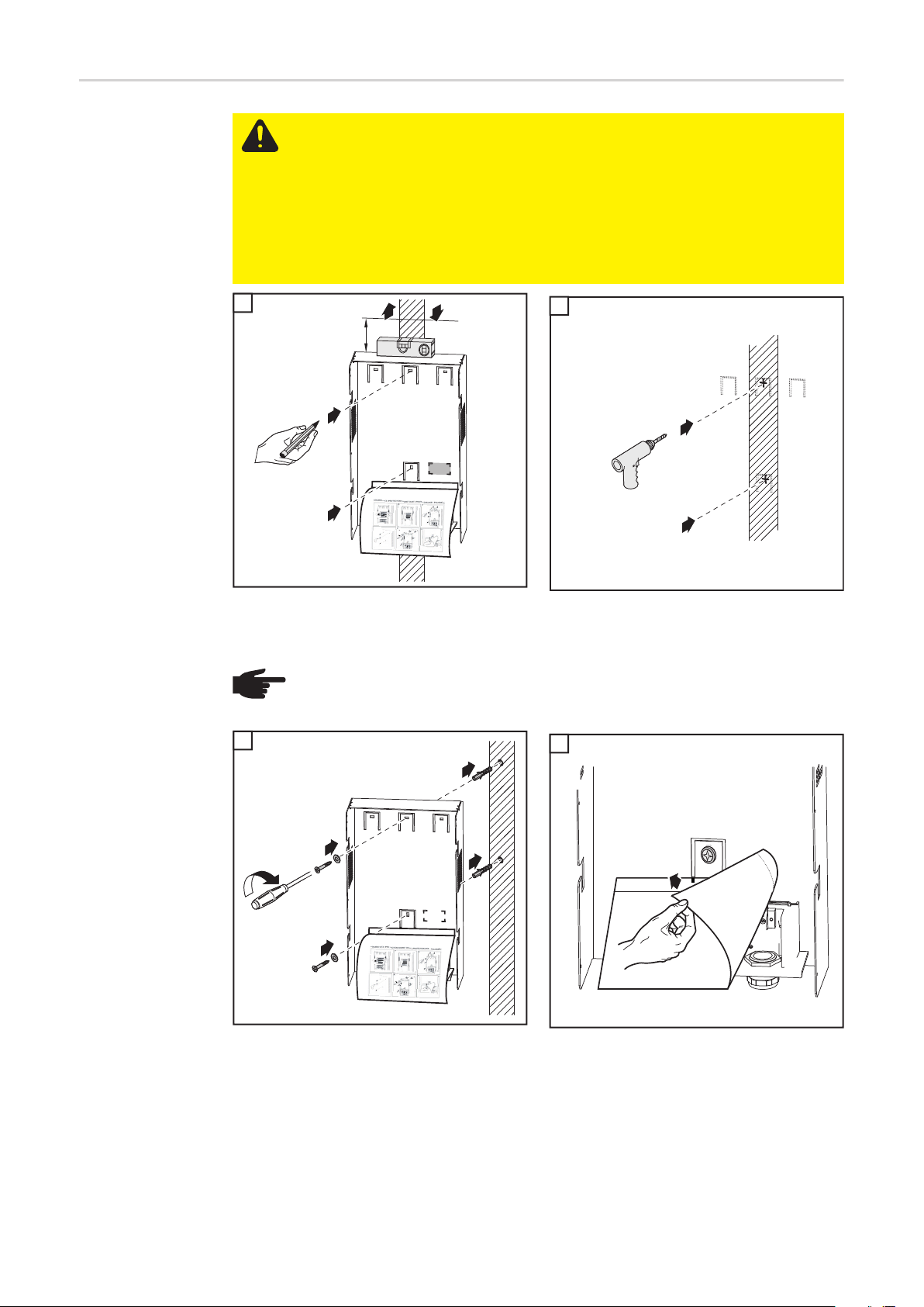
Attaching the wall
bracket - Wall installation
CAUTION! The inverter can be damaged by soiling or water on the terminals and
contacts of the connection area.
- When drilling, make sure that terminals and contacts in the connection area
do not become soiled or wet. Leave the dust cover in position.
- The wall bracket apart from the power stage set does not possess the degree
of protection of the complete inverter and, therefore, should not be attached
without a power stage set.
Protect the wall bracket against soiling and moisture during installation.
EN-US
1
min. 50 mm
min. 2 in.
2
3
4
1 2
1
1
(*)
2
1
2
3
IMPORTANT! Attach the wall bracket so that the display marking (*) on the wall bracket is
at eye level.
NOTE! When attaching the wall bracket to the wall, make sure that the wall bracket is not warped or deformed.
3
2
4
1
3
4
1
2
4
1
29
Attaching the wall
bracket - Column
installation
CAUTION! The inverter can be damaged by soiling or water on the terminals and
contacts of the connection area.
- When drilling, make sure that terminals and contacts in the connection area
do not become soiled or wet. Leave the dust cover in position.
- The wall bracket without the power stage set does not possess the same degree of protection as the complete inverter and, therefore, should not be attached without a power stage set.
Protect the wall bracket from soiling and moisture during installation.
1
min. 50 mm
min. 2 in.
2
1
1
2
2
1
(*)
3
1
2
IMPORTANT! Attach the wall bracket so that the display marking (*) on the wall bracket is
at eye level.
NOTE! When attaching the wall bracket to the wall, make sure that the wall bracket is not warped or deformed.
3
1
2
4
30
2
3
1
1
1
3
4
1
2
4

Connecting Fronius IG TL Dummy to the Public Grid
Using a Separate Power Supply Unit
General Dummy devices receive their power supply from the power unit provided with the dummy
device.
IMPORTANT! Do not connect any live AC cables to the AC terminals on the wall brackets.
You may connect live cables or cable pieces for demonstration purposes.
EN-US
Connecting Fronius IG TL Dummy to the Public
Grid Using a Separate Power Supply Unit (AC)
1
1
AC ~
100 - 240 V
50 / 60 Hz
1
31

Connecting the Fronius IG TL to the public grid (AC)
Monitoring the
Grid
AC terminals
IMPORTANT! The resistance in the leads to the AC-side connection terminals must be as
low as possible for optimal functioning of grid monitoring.
Legend:
AC
PE N LPE
PE(a)
NOTE! Connect the phase (L), neutral conductor (N), and grounding conductor
(PE) cables correctly!
L Phase conductor
N Neutral conductor
PE Grounding conductor / Ground
PE (a) Connection option for additional
ground
Max. cable cross section per conductor cable:
16 mm²
Min. cable cross section per conductor cable:
corresponds to the AC-side overcurrentprotected value, but at least 2.5 mm²
Connecting Aluminum Cables
The AC-side terminals are designed for connecting single-wire, round aluminum cables.
The following points must be taken into account when connecting aluminum cables due to
the non-conducting oxide layer of aluminum:
- reduced rated currents for aluminum cables
- the connection requirements listed below.
NOTE! Take into account local specifications when configuring cable cross sections.
Connection Requirements:
Carefully clean off the oxide layer of the stripped end of the cable, e.g., using a knife.
1
IMPORTANT! Do not use brushes, files, or sandpaper; aluminum particles may get stuck
and can transfer to other cables.
After removing the oxide layer of the cable end, rub in a neutral grease, e.g., acid-free
2
and alkali-free Vaseline.
Then immediately connect it to the terminal.
3
Repeat the steps above whenever the cable is disconnected and then reconnected.
32

AC cable cross
section
For a standard M32 metric screw joint with a reducer:
Cable diameter 7 - 15 mm
For an M32 metric screw joint (reducer removed):
Cable diameter 11 - 21 mm
(a cable diameter of 11 mm reduces the strain relief force from 100 N to a max. of 80 N)
For an M40 metric screw joint (option):
Cable diameter 19 - 28 mm
If required, use reducers for smaller cable diameters.
EN-US
Safety
Connecting the
Fronius IG TL to
the public grid
(AC)
WARNING! An electric shock can be fatal. Danger from grid voltage and DC volt-
age from solar modules.
- Never work with live wires! Prior to all connection work, make sure that the
AC and DC wires are not charged.
- Only an authorized electrician is permitted to connect this inverter to the public grid.
CAUTION! Danger of damaging the inverter from improperly connected terminals. Improperly connected terminals can cause thermal damage to the inverter
and may cause a fire. When connecting the AC and DC cables, make sure that
all terminals are tightened securely using the proper torque.
NOTE! Finely stranded cables up to conductor class 5 can be connected to the
AC-side terminals without wire end ferrules.
1
1
OFF
2
*
3x
6
5
4
3
AC
12 mm
60-80 mm
1 1
NOTE! When attaching the AC cable using metric screw joints, make sure that no
kinks form in the connected conductor cables. Otherwise, you may no longer be
able to close the inverter.
7
1
2
**
* Tightening torque:
min. 1.5 Nm
max. 1.7 Nm
** Tightening torque: 7.5 Nm
33

NOTE!
- Make sure that the grid neutral conductor is grounded. For IT networks (isolated networks without grounding), this is not the case, and operation of the
inverter is not possible.
- To use the inverter, a neutral conductor connector is required.
The infeed of the inverter can be adversely affected by a neutral conductor
with small dimensions. Therefore, the neutral conductor must have the same
dimensions as the other current-bearing conductors.
Maximum ACside Overcurrent
Protection
Inverter Number of
phases
Fronius IG TL 3.0 1 3130 W 1 x C 20 A
Fronius IG TL 3.6 1 3760 W 1 x C 20 A
Fronius IG TL 4.0 1 4190 W 1 x C 32 A
Fronius IG TL 4.6 1 4820 W 1 x C 32 A
Fronius IG TL 5.0 1 5250 W 1 x C 32 A
NOTE! The inverter is equipped with a universal current-sensitive RCMU according to DIN VDE 0126-1-1. This monitors residual currents from the solar module
up to the inverter grid connection and disconnects the inverter from the grid when
an improper residual current is detected.
If an external residual current circuit breaker is required due to local regulations,
it must have a rated current of at least 100 mA.
In this case, a type A residual current circuit breaker can be used.
If more than one inverter is used, a rated current of 100 mA must be provided for
each connected inverter; for example, for two inverters connected to a common
residual current circuit breaker, a residual current circuit breaker with at least
200 mA must be used.
Max. output Fuse protection
34

Connecting Solar Module Strings to the Fronius IG
TL (DC)
EN-US
Fronius IG TL
field of application
General information about solar
modules
NOTE! The inverter is designed exclusively to be connected and used with non-
grounded solar modules. The solar modules must correspond to protection class
II and class A according to IEC 61730, and they cannot be grounded at either the
positive or negative pole. Use with other DC generators (e.g., wind generators) is
not permitted.
In order to select suitable solar modules and get the most efficient use out of the inverter,
please note the following points:
- The open circuit voltage of the solar modules increases as the temperature decreases
(assuming constant irradiance). Open circuit voltage may not exceed 850 V.
If the open circuit voltage exceeds 850 volts, the inverter may be damaged, and all
warranty rights will become null and void.
- Note the temperature coefficients in the solar module data sheet
- More exact data for sizing the solar array for the particular location can be obtained
using calculations tools such as the Fronius Solar.configurator (available at http://
www.fronius.com).
NOTE! Before connecting solar modules, make sure that the voltage specified by
the manufacturer corresponds to the actual measured voltage.
Note the safety instructions and specifications of the solar module manufacturer
regarding solar module grounding.
Solar modules that require a ground at the positive or negative pole cannot be
used with the Fronius IG TL.
Safety
WARNING! An electric shock can be fatal. Danger from grid voltage and DC volt-
age from solar modules.
- Never work with live wires! Prior to all connection work, make sure that the
AC and DC wires are not charged.
- Only an authorized electrician is permitted to connect this inverter to the public grid.
CAUTION! Danger of injury from hazardous electrical voltage. Transformerless
systems can transfer leakage currents to solar module frames and mounts due to
their topology.
Connect and ground all solar module frames and mounts and other conductive
surfaces.
To ground solar module frames or mounts, please refer to the specifications provided by the solar module manufacturer and national guidelines.
CAUTION! Danger of damaging the inverter from improperly connected terminals. Improperly connected terminals can cause thermal damage to the inverter
and may cause a fire. When connecting the AC and DC cables, make sure that
all terminals are tightened securely using the proper torque.
CAUTION! Overloading the inverter may damage it. Only connect a maximum of
20 A to each DC terminal.
35

DC terminals
Connecting aluminum cables
DC+
DC+ and DC- terminals on the Fronius IG TL
DC-
The DC-side terminals are designed for connecting single-wire, round aluminum cables.
The following points must be taken into account when connecting aluminum cables due to
the non-conducting oxide layer of aluminum:
- Reduced rated currents for aluminum cables
- The connection requirements listed below
NOTE! Take into account local specifications when configuring cable cross sections.
Cable cross section of solar module strings
Connection Requirements:
Carefully clean off the oxide layer of the stripped end of the cable, e.g., using a knife.
1
IMPORTANT Do not use brushes, files or sandpaper. Aluminum particles may get stuck
and can transfer to other cables.
After removing the oxide layer of the cable end, rub in a neutral grease, e.g., acid- and
2
alkali-free Vaseline.
Then immediately connect it to the terminal.
3
Repeat the steps above whenever the cable is disconnected and then reconnected.
The cable cross section for solar module strings should be a maximum of 16 mm² per cable.
The min. cable cross section should be 2.5 mm².
NOTE! To ensure that the strain relief device is effective for solar module strings,
only use cable cross sections of the same size.
36

Polarity reversal
of solar module
strings
The inverter comes standard with 6 metal bolts in fuse holders in the power stage set.
These metal bolts ensure that the inverter is protected against reversed polarity. Reverse
polarity in the solar module strings will not cause any damage to the inverter.
If string fuses are used instead of metal bolts, reverse polarity in an individual solar module
string can cause damage to the inverter and may cause an inverter fire.
CAUTION! Risk of damage and fire to inverter due to reverse polarity of solar
module strings when using string fuses.
Reverse polarity of solar module strings can lead to an unacceptable overload to
a string fuse being used. This can cause a strong arc, which can lead to an inverter fire.
When using string fuses, always make sure that the polarity is correct before connecting the individual solar module strings.
EN-US
Information on
Dummy Devices
Connecting Solar
Module Strings to
the Fronius IG TL
(DC)
A dummy device (which is labeled as such on its rating plate) should not be connected to
a photovoltaic system for real operation and may only be used for demonstration purposes.
IMPORTANT! When using a dummy device, you should never connect a live DC cable to
the DC connection sockets.
You may connect live cables or cable pieces for demonstration purposes.
The following section "Connecting Solar Module Strings to the Fronius IG TL (DC)" only
applies to genuine inverters.
NOTE! You should only remove the number of knockouts required for the available cables (e.g., 3 openings for 3 DC cables).
1
2
2
1
4
1
1
3
2
NOTE! Finely stranded cables up to conductor class 5 can be connected to the
DC-side terminals without wire end ferrules.
37

3
2
4
DC+
DC-
12 mm
2
1
1
5
6 x
2
*
1
1
6
6
4
3
5
1
* Tightening torque:
min. 1.5 Nm
max. 1.7 Nm
7
12 mm
1
2
8
2
1
6
4
3
5
38
1
NOTE! When attaching the DC cables using a strain-relief device, make sure that
no kinks form in the connected DC cables. Otherwise, you may no longer be able
to close the inverter.

9
1
10
1
* Tightening torque:
min. 1.5 Nm
max. 1.7 Nm
11
max. 850 V
6 x
2
*
1
3
**
4
2
1
EN-US
** Tightening torque:
min. 1.5 Nm
max. 1.9 Nm
IMPORTANT Check the polarity and voltage of the solar module strings: the voltage should be a max. of 850 V; the
difference between the individual solar
module strings should be a max. of 10 V.
1
39

Inserting String Fuses into the Fronius IG TL
General The steps described in the ‘Inserting String Fuses into the Fronius IG TL’ section should
only be carried out if the solar module manufacturer requires the use of string fuses for operation.
Selecting string
fuses
Safety
If the solar module manufacturer requires the use of string fuses for operation, select string
fuses according to the information from the solar module manufacturer or according to the
‘Criteria for the Proper Selection of String Fuses’ section:
- max. 20 A per fuse holder
- max. 6 DC inputs
- max. 11 A per measuring channel if solar module string monitoring is activated and
being used
- max. 20 A of total input current
- Fuse dimensions: Diameter 10.3 x 35 - 38 mm
IMPORTANT!
- Follow all solar module safety instructions
- Follow all solar module manufacturer requirements
WARNING! An electric shock can be fatal. Danger from grid voltage and DC voltage from solar modules.
- The DC main switch is used only to switch off power to the power stage set.
When the DC main switch is turned off, the connection area is still energized.
- Only licensed electricians should access the connection area.
- All maintenance and service work should only be carried out when the power
stage set has been disconnected from the connection area.
- Maintenance and service work on the inverter power stage set should only
be carried out by Fronius-trained personnel.
WARNING! An electric shock can be fatal. Danger from residual voltage from capacitors.
You must wait until the capacitors have discharged. Discharge takes 3 minutes.
40

Inserting string
fuses into the
Fronius IG TL
IMPORTANT! If you add string fuses at a later date, follow all safety information.
EN-US
CAUTION! If screws are not tightened correctly, there is a danger of damage re-
sulting from water getting into the device. The housing cover screws help to seal
the power stage set and must not be replaced by different screws.
1
1
4 x
1
2
2
2
4
4
1
2
3
3
3 4
3
- Carefully lift up the housing cover on
the bottom of the power stage set
- Reach into the opening
- Disconnect the ribbon cable from the
PC display board
4
1
2
1
3
4
41

NOTE!
- Use pliers to insert fuses with a fuse cover into their respective fuse holder
- To prevent the fuse from falling out, only insert the fuse cover into the fuse
holder with the opening upright.
- Do not operate the inverter without fuse covers
1
5
1
- Place the housing cover at an angle on
the power stage set so that there is an
opening at the bottom of the power stage set
- Reach into the opening
1
4
2
3
3
1
6
- Connect the ribbon cable to the display
PC board
* Tightening torque: 2.5 Nm
*
2
1
IMPORTANT! Check the polarity of solar module strings!
42

Criteria for the Proper Selection of String Fuses
General The use of string fuses in the inverter also adds fuse protection to the solar modules.
A crucial factor for the fuse protection of solar modules is the maximum short circuit current
Isc of the respective solar module.
EN-US
Criteria for the
Proper Selection
of String Fuses
Effects of Using
Underrated Fuses
Fuse recommendations
The following criteria must be met for each solar module string when using fuse protection:
-IN > 1.5 x I
-IN < 2.0 x I
-UN ≥ 850 V DC
- Fuse dimensions: Diameter 10.3 x 35 - 38 mm
I
N
I
SC
V
N
With underrated fuses, the nominal current value may be less than the short circuit current
of the solar module.
Effect:
The fuse may trip in intensive lighting conditions.
SC
SC
Nominal current rating of the fuse
Short circuit current for standard test conditions (STC) according to solar mod-
ule data sheet
Nominal voltage rating of the fuse
NOTE! Only select fuses suitable for a voltage of 850 V DC.
Application example
You should only use the following fuses, which have been tested by Fronius, to ensure
problem-free fuse protection:
- Cooper Bussmann PV fuses
Fronius shall not be liable for any damage or other incidents resulting from the use of other
fuses. Moreover, all warranty claims are voided.
Example: Maximum short circuit current (ISC) for the solar module = 5.75 A
According to the criteria for selecting the correct fuse, the fuse must have a nominal current
greater than 1.5 times the short circuit current:
5.75 A x 1.5 = 8.625 A
The fuse that should be selected according to the ‘Fuses’ table:
PV-10A10F with 10 A and nominal voltage of 1000 V DC.
43

Fuses
Nominal current
value
1.0 A PV-1A10F 6.0 A PV-6A10F
2.0 A PV-2A10F 8.0 A PV-8A10F
3.0 A PV-3A10F 10.0 A PV-10A10F
4.0 A PV-4A10F 12.0 A PV-12A10F
5.0 A PV-5A10F 15.0 A PV-15A10F
‘Fuses’ Table: Selection of suitable fuses, e.g., Cooper Bussmann fuses
Fuse Nominal current
value
Fuse
44

Clipping Power Stage Sets onto the Wall Bracket
EN-US
Clipping power
stage sets onto
the wall bracket
The side areas of the housing cover are designed to function as carrying grips and/or handles.
WARNING! An inadequate grounding conductor connection can cause serious
injuries to persons and damage to (or loss of) property. The housing screws provide an adequate grounding conductor connection for the housing ground and
should not be replaced under any circumstances by other screws that do not provide a proper grounding conductor connection.
1 1
1
2
*
2
1
1
1
1
1
2
1
1
* Tightening torque: 2 Nm
45

Data Communication and Solar Net
Fronius Solar Net
and Data Interface
Fronius developed Solar Net to make these system add-ons flexible and capable of being
used in a wide variety of different applications. Fronius Solar Net is a data network that
enables several inverters to be linked to the system add-ons.
Fronius Solar Net is a bus system with ring topology. Just one suitable cable is enough
to provide communication between one or more inverter connected to Fronius Solar Net
and a system add-on.
Different system add-ons are automatically recognized by Fronius Solar Net.
In order to distinguish between several identical system add-ons, each one must be as-
signed a unique number.
In order to clearly define each inverter in Fronius Solar Net, each inverter must also be
assigned an individual number.
You can assign individual numbers as per the "SETUP Menu" section in this manual.
More detailed information on individual system upgrades can be found in the relevant operating instructions or on the internet at http://www.fronius.com
More detailed information on cabling DATCOM components can be found at
http://www.fronius.com/QR-link/4204101938
Data communication rack
Overcurrent and
under-voltage
shutdown
The inverter is equipped with a rack for data communication devices on the bottom of the
unit.
The rack can be pulled out after removing the 2 screws, making the data communication
connections accessible.
IMPORTANT! When closing the data communication rack make sure that both screws
have been reattached in order to seal the inverter securely.
The data communication rack has a shutdown function that interrupts the energy supply to
Fronius Solar Net and to the 12 V signaling output:
- in the event of overcurrent, e.g., in case of a short circuit
- in the event of under-voltage
The overcurrent and under-voltage shutdown function does not depend on the direction of
the current flow. When a current flow of > 3 A or a voltage of < 6.5 V is measured in Fronius
Solar Net, the energy supply is interrupted to Fronius Solar Net.
The energy supply is re-established automatically.
46

Data communication connections
Data communication rack with connections:
(3)
(4)
(5)
(6)
USB OUT
Do not
disconnect
while LED is
flashing.
GND
12 V DC
EN-US
(1)
(2)
(1)
Item Description
(1) Screw for attaching the data communication rack
(2) Sealing insert for data communication cable
(3) USB A socket
for connecting a USB stick with a max. size of
l x w x h = 80 x 33 x 20 mm
A USB stick can act as a datalogger for an inverter. The USB stick is not part of
the scope of supply for the inverter.
(4) Solar Net IN connection
'Fronius Solar Net' input for connecting other DATCOM components (e.g., inverters, sensor cards)
(5) 'Data Transfer' LED
Flashes when logging data are being recorded
(6) Termination plug
When networking several DATCOM components, a termination plug must be
placed on each free IN and/or OUT connection of a DATCOM component.
The termination plug is not part of the scope of supply for the inverter.
(7) Safety information for removing USB sticks
(8) Solar Net OUT connection
'Fronius Solar Net' output for connecting other DATCOM components (e.g., in-
verters, sensor box)
(9) 12 V output (no contact)
Used to connect a finely stranded conductor with a max. 1.5 mm² cross section
for controlling common 12 V signaling systems such as alarm horns, indicator
lamps or installation relays; 12 V (+ 0 V / - 2 V / 300 mA)
(10) 'Solar Net' LED
Indicates the current status of Fronius Solar Net and the 12 V signaling output
(7)
(8)
(9) (10)
47

'Solar Net' LED
description
The 'Solar Net' LED lights up:
Power supply for data communication within Fronius Solar Net and the 12 V signaling output are OK
The 'Solar Net' LED flashes continually 3x per second:
Overcurrent or short circuit at the 12 V signaling output (e.g. connected consumer load is
too high or faulty), data communication in Fronius Solar Net is OK
The 'Solar Net' LED is off:
Error in data communication in Fronius Solar Net; the 12 V signaling output is deactivated
- Overcurrent (current flow > 3 A, e.g. due to a short circuit in Fronius Solar Net)
- Under-voltage (no short circuit, voltage in Fronius Solar Net < 6.5 V, e.g. if too many
DATCOM components are in Fronius Solar Net and the electrical supply is insufficient)
In this case, the DATCOM components require an external energy supply via an external power supply unit.
Check other DATCOM components to detect any under-voltage present.
The 'Solar Net' flashes briefly every 5 seconds:
After a shutdown due to over-current or under-voltage, the inverter tries to restore the energy supply in the Fronius Solar Net every 5 seconds so long as there is an error, for example.
Once the error has been corrected, power is restored to Fronius Solar Net within 5 seconds
and then to the 12 V signaling output 1 second later.
During this time the 'Solar Net' LED flashes 3x per second. Once there is no longer an error
at the signaling output, the 'Solar Net' LED lights up again.
Example Logging and archiving data from the inverter and sensor using a Fronius Datalogger Box
and Fronius Sensor Box:
Fronius
IG-TL
IN
OUT
Datalogger Box
IN OUT
Fronius
IG-TL
Fronius
IG-TL
Sensor Box
12 3
OUT
IN
OUT
IN
IN OUT
°C
m/s
W/m²
48
= terminating plug
Explanation of illustration:
Data network with 3 inverters, one Data Logger Box and one Sensor Box

External communication (Solar Net) takes place in the inverter via the data communication
rack. The data communication rack is equipped with two RS 422 interfaces - an input and
an output.
RJ45 plug connectors are used to establish the connection.
EN-US
Maximum output
current for data
communication
and the 12 V signaling output
Connecting data
communication
cables to inverters
The maximum total output current for data communication and the 12 V signaling output is
500 mA, which can be divided up as follows:
Data communication 200 mA 500 mA
12 V signaling output + 300 mA + 0 mA
Total 500 mA 500 mA
For more information about DATCOM components, see the "DATCOM Detail" operating
instructions.
1 2
1
5x
1
2
1
3
2
3
"click"
4
2
1
2
1
3
IMPORTANTWhen networking several
DATCOM components, a terminating plug
must be placed on each free IN or OUT
connection of a DATCOM component.
IMPORTANT Close any unused openings
at the sealing insert using the appropriate
blanking plugs.
3
2
3
1
49

USB Stick as a Data Logger and for Updating Inverter Software
USB stick as a
data logger
Data on the USB
stick
A USB stick connected to the USB A socket can act as a data logger for an inverter.
Logging data saved to the USB stick can at any time
- be imported into the Fronius Solar.access software via the included FLD file,
- be viewed directly in third-party applications (e.g., Microsoft® Excel) via the included
CSV file.
Older Excel versions (up to Excel 2007) have a row limit of 65536.
If a USB stick is used as a data logger, three files are automatically created:
- System file *.sys:
This file saves information from the inverter that is irrelevant to the customer. The file
must not be deleted individually. Only delete all files together (sys, fld, csv).
- Log file TLxxx_yy.fld (xxx = IG number, yy = a serial 2-digit number):
Log file for reading out data in Fronius Solar.access.
You can find additional information on the Fronius Solar.access Software in the "DATCOM Detail" operating instructions at http://www.fronius.com
- Log file TLxxx_yy.csv (xxx = IG number, yy = a serial 2-digit number):
A log file for reading out data in a spreadsheet program (e.g., Microsoft® Excel)
Structure of the CSV file:
(1) (2) (3) (4)
50

(5) (6) (7)
(1) ID
(2) Inverter no.
(3) Inverter type (DATCOM code)
(4) Logging interval in seconds
(5) Energy in watt-seconds with reference to the logging interval
(6) Averages over the logging interval
(7) Additional information
EN-US
Data amount and
memory capacity
One USB stick with a memory capacity of 128 MB, for example, can record logging data at
a logging interval of 5 minutes for approx. 7 years.
CSV file
CSV files can store only 65535 rows (data records) (up to Microsoft® Excel version 2007,
afterwards there is no limit).
At a logging interval of 5 minutes, the 65536 rows are written within approx. 7 months (CSV
data size of approx. 8 MB).
To avoid loss of data, the CSV file should be backed up to a PC within these 7 months and
deleted from the USB stick. If the logging interval is set longer, this time frame is extended
accordingly.
FLD file
The FLD file should not be larger than 16 MB. At a logging interval of 5 minutes, this corresponds to a storage duration of approx. 7 years.
If the file exceeds this 16 MB limit, it should be backed up to a PC, and all data should be
deleted from the USB stick.
After you have backed up the data and removed it from the USB stick, the stick should be
immediately reinserted so that it can record logging data; no further steps are required.
NOTE! A full USB stick can lead to the loss of data or the overwriting of data.
When inserting the USB stick, make sure that it has sufficient memory capacity.
51

Buffer memory If the USB stick is removed (e.g., to back up data), the logging data are written to a buffer
memory in the inverter.
As soon as the USB stick is reinserted, the data are automatically transferred from the buffer memory to the USB stick.
The buffer memory can store a maximum of 24 logging points. Data are logged only during
inverter operation (power greater than 0 W). The following time spans for storing data result from the different logging intervals:
Logging interval [min] Time span [min]
5 120
10 240
15 360
20 480
30 720
When the buffer memory is full, the oldest data in the buffer memory are written over with
the new data.
IMPORTANT The buffer memory requires a constant power supply.
If there is an AC power outage during operation, all data in the buffer memory are lost. The
automatic night switch-off must be deactivated so that the data are not lost at night (set
'Night Mode' to ON - see chapter "Setting and Displaying Menu Items," section "Displaying
and setting parameters in the 'DATCOM' menu item").
Suitable USB
sticks
Due to the number of USB sticks on the market, we cannot guarantee that every USB stick
will be recognized by the inverter.
Fronius recommends using only certified, industrial USB sticks (look for the USB-IF logo).
The inverter supports USB sticks using the following file systems:
- FAT12
- FAT16
- FAT32
Fronius recommends that the USB stick only be used for recording logging data or for updating the inverter software. USB sticks should not contain any other data.
52

USB symbol on the inverter display, e.g.,
in the ‘NOW’ display mode
USB stick for updating inverter
software
When the inverter recognizes a USB stick,
the USB symbol will appear at the top right
of the display.
When inserting the USB stick, make sure
that the USB symbol is displayed (it may
also be flashing).
NOTE! Please be aware that in outdoor applications the USB stick may only function in a limited temperature range. Make sure, for example, that the USB stick
will also function at low temperatures for outdoor applications.
End customers can also use the USB stick to update the inverter software: The update file
is first saved to the USB stick and then transferred to the inverter.
For more information about updating inverter software using a USB stick, please see the
section ‘Setting and Displaying Menu Items’ in the chapter ‘Operation.’
EN-US
Removing the
USB stick
The inverter software can be updated through a data logger or a Fronius SmartConverter
(= through a PC/ laptop connection) in conjunction with the Fronius solar.update Software
(see ‘Fronius Solar.update’ operating instructions.)
Safety information for removing a USB
stick
IMPORTANT To prevent the loss of data,
Do not
disconnect
while LED is
flashing.
the connected USB stick should only be
removed under the following conditions:
- Only via the Setup menu, ‘USB / Disconnect Device’ menu item
- When the ‘Data Transfer’ LED is no
longer flashing or lit
53

First startup
Factory pre-set
configuration
The inverter has been pre-configured at the factory. The language and time must be set
during the first startup.
To change your inverter settings, please see ‘The Setup Menu’ section in these instructions.
First startup Once the inverter has been connected to the solar modules (DC) and the public grid (AC),
turn the main switch to position - 1 -.
NOTE! To ensure the inverter maintains its degree of protection:
- Insert blanking plugs into all openings at the sealing insert where there are
no cables
- If cables are run through the sealing insert, insert the remaining blanking
plugs in the recesses located on the outside
1 2
1
2
1
2
3
- As soon as the solar modules produce sufficient power, the Startup LED lights up orange. The inverter switches to the Startup phase. The orange LED indicates that the
feed-in mode of the inverter will begin shortly.
- After the automatic inverter start, the Operating Status LED lights up green.
- Provided that power continues to feed into the grid, the Operating Status LED will remain green to confirm that the inverter is functioning correctly.
- A display appears for setting the language:
Use the ‘Up’ and ‘Down’ keys to se-
3
lect the desired language.
Press the ‘Enter’ key to apply the lan-
4
guage.
54
- Finally, the time and date must still be set:

The time is shown as
(HH:MM:SS, 24 h display),
the digits for the hour flash.
Use the ‘Up’ and ‘Down’ keys to se-
5
lect a value for the hour.
Press the "Enter" key.
6
The digits for the minutes flash.
Repeat steps 5 and 6 for the minutes
7
and seconds until...
the set time flashes.
EN-US
Press the ‘Enter’ key
8
The time is applied, the date is shown
(DD.MM.YYYY), the digits for the day
flash.
Use the ‘Up’ and ‘Down’ keys to se-
9
lect a value for the day.
Press the ‘Enter’ key
10
The digits for the month flash.
Repeat steps 9 and 10 for the month
11
and the last 2 digits of the year until...
55

the set date flashes.
Press the ‘Enter’ key
12
If the language and time settings are skipped with the Back key and no settings are made
in the Setup, these two queries will appear again the next time the inverter starts.
56

Operation


Keys and symbols
Keys and Symbols
EN-US
(8)
(1)
Item Description
(1) Display
for displaying values, settings and menus
Function keys - each has a different function depending on the selection:
(2) ‘Left/Up’ key
for navigating left and up
(3) ‘Down/Right’ key
for navigating down and right
(4) 'Menu/Esc' key
for switching to the menu level
to exit the Setup menu
(5) 'Enter' key
for confirming a selection
(2)
(3)
(4)
(7)
(6)
(5)
Control and Status LEDs
(6) Operating status LED (green)
for displaying the operating status
(7) Startup LED (orange)
indicates whether or not the inverter is in the start phase or in standby mode
(8) General Status LED (red)
indicates when a status message is shown on the display
59

Display Power for the display comes from the AC grid voltage. The display can be available all day
long depending on the setting in the Setup menu.
IMPORTANT! The inverter display is not a calibrated measuring instrument. Slight deviation of a few percentage points from the utility company meter is intrinsic to the system. A
calibrated meter is required to make calculations for the utility company.
Display modes
Parameter explanation
Display of values and units as well as
status codes
Function key assignment
Display area, display mode
Energy Management (**)
Inverter no. | USB conn. | Storage sym. (***)
Symbols for function key functions
1
Display modes
Preceding menu items
Currently selected menu item
Next menu items
(*)
Display area, setup mode
Function key assignment
(*) Scroll bars
(**) The Energy Manager symbol
is displayed, if the Energy Manager function has been activated
(***) WR no. = InverterDATCOM number,
Store icon - appears briefly when set values are stored,
USB connection - appears if a USB stick has been inserted
The following symbols are shown on the display for function key assignment:
Navigation: Left
60
Navigation: Up
Increase value
Navigation: Right
Navigation: Down
Reduce value

Menu / Back
Control and Status LEDs
Enter
(1) General Status LED (red)
(2) Startup LED (orange)
(3) Operating Status LED (green)
(1)
(2)
(3)
LED Color Action Explanation
(1) red lights up General status: the appropriate status code is
shown on the screen
Interruption of feed operation
During troubleshooting (the inverter is waiting to
be reset or for an error to be corrected)
(2) orange lights up The inverter will enter the automatic startup or
self test phase as soon as the solar modules
yield sufficient power output after sunrise
the inverter has been set to standby operation in
the setup menu (= manual shutoff of operation)
The inverter software is being updated
(3) green lights up A green light lights up as soon as the inverter has
completed the startup phase, and stays green as
long as the operation of feeding power into the
grid continues.
It indicates problem-free operation of the photovoltaic system.
EN-US
A list of most status codes, the corresponding status information, their status causes and
repair measures can be found in the chapter ‘Troubleshooting and Maintenance’, under the
section ‘Status diagnosis and troubleshooting.’
61

Startup Phase and Grid Feed-in Mode
Startup phase The inverter automatically carries out the following tests and checks after it is turned on:
a) Self-test of essential inverter components - the inverter goes through a virtual checklist
b) Synchronization with the grid
c) Startup test
Before the inverter starts feeding energy into the grid, the conditions of the grid are
tested in accordance with local regulations.
The startup test can take anything from just a few seconds to several minutes depending on national regulations.
During the startup phase
- The operating status LED lights up orange,
- ‘wait ...’ appears on the display and the component currently being tested is displayed,
e.g.:
The operation of
feeding energy
into the grid
- After the tests are completed, the inverter starts feeding energy into the grid.
- Once connected to the grid, the inverter checks the relay function without power: within 1 second, several relay switching operations can be heard.
- The display shows the present power feeding into the grid, e.g.:
- The Operating Status LED lights up green, and the inverter starts operating.
62

Navigation in the Menu Level
EN-US
Activating display
illumination
Automatic Deactivation of Display
Illumination /
Switching to the
"NOW" Display
Mode
Accessing the
menu level
Press any key.
1
The display illumination is activated.
The Setup menu also offers a choice between a permanently lit or permanently dark
display.
If no key is pressed for 2 minutes:
- the display illumination turns off automatically and the inverter switches to the "NOW"
display mode (if the display illumination is set to automatic)
- the inverter can be switched to the "NOW" display mode from any menu level, except
for the "Standby" menu item
- the current output power is displayed.
Press the ‘Menu’ key.
1
‘Menu’ appears on the display.
The inverter is now at the menu level.
From the menu level you can
- Set the desired display mode
- Access the Setup menu
63

The Display Modes
Display modes The following display modes are available for the inverter:
The ‘NOW’ display mode ...... Displays real-time values
The ‘TODAY’ display mode ...... Displays values for power fed into the grid during
that day
The ‘YEAR‘ display mode ...... Shows data for the current calendar year
The ‘TOTAL’ display mode ...... Displays values for power fed into the grid since
your inverter first started operating
Selecting a display mode
Access the menu level
1
Use the ‘left’ or ‘right’ keys to select
2
your preferred display mode
Press the ‘Enter’ key
3
The first display value of the selected display mode is shown.
64

Overview of display values
Display mode Unit Display value
‘NOW’ W Output Power
Daily Characteristic Curve
V AC Grid Voltage
A Output Current
Hz AC Grid Frequency
V PV Array Voltage
A Solar Power
String Control Status
‘TODAY’
‘YEAR’
HH:MM
DD.MM
SS
YY
kWh / MWh Fed-In Energy
Clock
Date
Daily Characteristic Curve (‘TODAY’)
‘TOTAL’ Currency Yield
g / kg CO2 Savings
W Max. Output
V Max. Grid Voltage
V Max. PV Array Voltage
HH:MM Operating Hours
EN-US
65

Display Values in the ‘NOW’ Display Mode
Selecting a display mode
Display values in
the ‘NOW’ display
mode
First display value in the ‘NOW’ display mode
Selecting the ‘NOW’ display mode
1
The first display value appears in the
‘NOW’ display mode.
Use the ‘Down’ key to scroll to the
2
next display value.
Use the ‘Up’ key to scroll back.
Output
power supplied to the grid at a given moment
(Watts)
Press the ‘Enter’ key to display the daily charac-
teristic curve.
Daily Characteristic Curve
graphically represents the course of power output
during the day. The time axis is automatically
scaled.
Press the ‘Back’ key to close the display.
Grid Voltage
(Volts)
Output Current
current supplied to the grid at a given moment
(Amperes)
Grid Frequency
(Hertz)
66

Array Voltage
voltage of the solar array at the moment of data
display
(Volts)
Solar Power
current supplied by solar array at the moment of
data display (Amperes)
Press the ‘Enter’ key to arrive at the ‘String Con-
trol Status’ menu
String Control Status
displays the PV array current produced during the
day on channel 1 and channel 2, respectively, and
the present deviation between them.
Press the ‘Back’ key to close the display.
Time
When the time on the inverter or a system up-
grade is changed, this changes the time on all de-
vices connected via Solar Net.
EN-US
Date
When the date on the inverter or a system up-
grade is changed, this changes the date on all de-
vices connected via Solar Net.
67

Display Values in the ‘TODAY’ / ‘YEAR’ / ‘TOTAL’
Display Modes
Selecting the ‘TODAY’ / ‘YEAR’ /
‘TOTAL’ display
mode
The First Display Value in the ‘TODAY’ Display
Mode
The first display value in the ‘YEAR’ display
mode
Selecting the ‘TODAY,’
1
‘YEAR,’ or
‘TOTAL’ display mode
The first display value appears in the selected display mode.
Use the ‘Down’ key to scroll to the
2
next display value.
Use the ‘Up’ key to scroll back.
68
The first display value in the ‘TOTAL’ display
mode

Display values in
the ‘TODAY’ /
‘YEAR’ / ‘TOTAL’
display modes
Output Energy
energy fed into the grid over a given period of time
(kWh / MWh)
Press the ‘Enter’ key to display the daily charac-
teristic curve (only in the ‘Today’ display mode).
Daily Characteristic Curve
graphically represents the course of the output
power during the day. The time axis is automati-
cally scaled.
Press the ‘Back’ key to close the display.
Due to the variety of different monitoring systems, there can be deviations between the
readings of other metering instruments and the readings from the inverter. For determining the energy supplied to the grid, only the readings of the calibrated meter supplied by
the electric utility company are relevant.
Yield
Amount of money earned during the period of time
in question (currency can be selected in the Setup
menu)
EN-US
As was the case for the output energy, readings may differ from those of other instruments.
‘The Setup menu’ section describes how to set the currency and rate for the energy supplied. The factory setting depends on the respective country-specific setup.
CO2 Savings
CO2emission (g / kg) saved during the period
monitored
The CO2 meter gives an indication of CO2 emissions that would be released during the
generation of the same amount of electricity depending on the available power plant.
The factory setting is 0.59 kg / kWh (source: DGS - German Society for Solar Energy).
Maximum Output Power
highest output power during observation period
(W)
69

Maximum grid voltage
Highest reading of grid voltage (V) during obser-
vation period
maximum PV Array Voltage
highest reading of solar module voltage (V) during
observation period
Operating Hours
indicates how long the inverter has been operat-
ing (HH:MM).
Although the inverter does not operate during the night, all sensor data are recorded
around the clock for the Sensor Box option.
IMPORTANTThe time must be set correctly for day and year values to be displayed properly.
70

The Setup Menu
Presetting The inverter is pre-configured and ready to use. No manual control is necessary for feeding
the power it generates into the grid.
The setup menu allows easy readjustment of the inverter's preset parameters to your
needs.
EN-US
Accessing the
Setup menu
‘SETUP’ mode selected at the menu level
‘Standby’ menu item
Switch to the menu level
1
(by pressing the ‘Menu’ key).
Select the ‘SETUP’ mode using the
2
‘Left’ or ’Right’ keys.
Press the ‘Enter’ key.
3
The Setup menu’s first menu item ‘Standby’ is shown.
Scrolling through
menu items
Example: ‘Standby’ menu item Example: ‘Contrast’ menu item
Accessing the Setup menu
1
Scroll through the available menu items using the ‘Up’ and ‘Down’ keys.
2
71

Menu Items in the Setup Menu
Standby Manual activation/deactivation of the standby mode
Unit Setting range Enter
Factory setting ‘Standby’ deactivated
- The power electronics are switched off in standby mode. No power is fed into the grid.
- The Startup LED lights up orange.
- In standby mode, no other menu item can be accessed or set in the Setup menu.
- Automatic switching to the ‘NOW’ display mode after 2 minutes if no key is pressed is
not activated.
- The standby mode can only be deactivated manually by pressing the ‘Enter’ key.
- Grid supply operation can be resumed at any time (deactivate ‘Standby’).
Setting standby mode (manual shutoff for feeding energy into the grid):
Select the ‘Standby’ menu item.
1
Press the ‘Enter’ key.
2
The display alternates between ‘STANDBY’ and ‘ENTER.’
The Standby mode is now activated.
The Startup LED lights up orange.
Restoring the grid feed:
In Standby mode, the display alternates between ‘STANDBY’ and ‘ENTER.’
Press ‘Enter’ to restore the grid feed.
1
The menu item ‘Standby’ is shown.
The inverter also switches to the Startup phase.
After the grid feed is restored, the Operation Status LED lights up green.
Contrast Contrast setting on LCD display
Unit Setting range 0 - 10
Factory setting 5
Since contrast depends on temperature, it may be necessary to adjust the ‘Contrast’ menu
item when ambient conditions change.
72

Backlight Initial setting for display illumination.
Unit Setting range AUTO / ON / OFF
Factory setting AUTO
AUTO: The display illumination is activated by pressing any key. If no
key is pressed for 2 minutes, the display backlight goes out.
ON: The display illumination will be permanently on when the invert-
er is active.
OFF: The display illumination will be permanently off.
IMPORTANT! The ‘Backlight’ menu item only applies to the display background illumination and key illumination.
Language Setting the display language
EN-US
Unit Display range German, English, French, Dutch, Italian, Spanish, Czech, Slo-
vak
Factory setting (depends on the country setup)
Currency Currency setting and rate for invoicing the energy supplied
Unit Display range Currency / Feed-in tariff
Factory setting (depends on the country setup)
CO2 Factor Setting the CO2 reduction factor
Unit kg/kWh
Setting range 00,01 - 99,99
Factory setting 0.59 kg/kWh
73

Yield Setting
- an OFFSET value for the Total energy display
- a measurement correction value for the day, year and total energy display
Setting range Energy Meter Offset / Energy Meter Unit / Meter Calibration
Energy Meter Offset
Specification of a value for the energy supplied that is added to the currently supplied energy (e.g., the transfer value when an inverter is replaced)
Unit Wh
Setting range 5-digit
Factory setting 0
Energy Meter Unit
Assignment of the SI prefix (k..., M...)
Unit Setting range k / M
Factory setting -
Meter Calibration
Specification of a correction value so that the data shown on the inverter display correspond to the calibrated data shown on the electric meter
Unit %
Setting range -5,0 - +5,0
Factory setting 0
DATCOM Check of a data communication, entry of the inverter number, DATCOM night mode, pro-
tocol settings
Setting range Status / inverter number / night mode / protocol type
Status
Displays data communication available via Solar Net or an error that occurred in data communication
Inverter Number
Number setting (address) of the inverter in a setup where multiple solar inverters are linked
together
Unit Setting range 00 - 99 (00 = 100 inverter)
Factory setting 01
74
IMPORTANT! Each inverter must be assigned its own address when using multiple inverters in a data communications system.

Night Mode
DATCOM night mode; controls DATCOM and display operation at night or when there is
not enough DC voltage available
Unit Setting range AUTO / ON / OFF
Factory setting AUTO
AUTO: DATCOM operation is constant as long as a Data logger is con-
nected to an active, uninterrupted Solar Net.
The display is dark during the night and can be activated by
pressing any key.
ON: DATCOM operation is constant as long as DATCOM compo-
nents are connected to Solar Net (even when Solar Net is interrupted). The inverter provides 12 V constantly to supply Solar
Net with power.
The display is always active.
IMPORTANT When the DATCOM night mode is ON or on
AUTO with connected Solar Net components, the power consumption of the inverter is increased at night to 7.3 W.
EN-US
OFF: No DATCOM operation at night, the inverter requires no AC
power to supply Solar Net.
The display is deactivated at night.
Protocol Type
Defines the communication protocol used to transmit data:
Unit Setting range Solar Net / Interface
Factory setting Solar Net
Signal relay Data communication control, signal activation, signal settings, signal test, DATCOM night
mode, protocol settings
Setting range Signal Mode / Signal Test / Switch on Point* / Switch off Point*
* are only shown if the 'E-manager' function has been activated under 'Signal Mode.
Signal Mode
for selection of the various functions of the 12 V output to the data communications rack:
- Alarm function
- Active output
- Energy manager
Unit Setting range ALL / Permanent / OFF / ON / E-manager
Factory setting ALL
75

Alarm function:
Permanent / ALL: Switches the 12 V output for continual and temporary service
codes (e.g., brief interruption of power being fed into the grid, a
service code occurring more than 50 x per day)
Active output:
ON: The 12 V output is turned on continually while the inverter is op-
erating (as long as the display lights up or displays.)
OFF: The 12 V output is switched off.
Energy manager:
E-manager: Via the 'Energy manager' function, the 12 V output can be trig-
gered by assigning a power feed dependent switch-on or
switch-off point, so that this functions as an actuator.
You can find additional information on the 'Energy manager'
function in the following sections:
- Energy manager
- Energy manager: Notes on configuring the switch-on and
switch-off points
- Energy manager: Example
Signal Test
Function test to determine whether or not the 12 V message output turns on periodically
Switch on point
(only when the 'Energy manager' function is activated)
for setting the effective power limit at which the 12 V output is switched on
Factory setting: 20% of the power rating
Setting range Switch off point - max. power rating of the inverter / W / kW / MW
Switch off point
(only when the 'Energy manager' function is activated)
for setting the effective power limit at which the 12 V output is switched off
Factory setting: 0
Setting range 0 - Switch on point / W / kW / MW
Energy manager Via the 'Energy manager' function, the 12 V output can be triggered so that this functions
as an actuator.
A user connected to the 12 V output can thus be controlled by assigning a power feed dependent switch-on or switch-off point.
76
The 12 V output is switched off automatically
- When no current is being fed into the public grid supply by the inverter;
- When the inverter is switched manually to standby mode;
- When there is an effective power assignment of 10% of the power rating;
- When there is insufficient solar radiation.

To activate the 'Energy manager' function, select 'E-manager' and press the 'Enter' key.
When the 'Energy manager' function is activated, the 'Energy manager' icon is displayed
at the top left of the display:
When the 12 V output is switched off (open contact)
When the 12 V output is switched on (closed contact)
To deactivate the 'Energy manager' function, select another function and press the 'Enter'
key.
EN-US
Energy manager:
Notes on configuring the switchon and switch-off
points
Energy manager:
Example
Pay attention to the following when configuring the switch-on and switch-off points:
Insufficient difference between the switch-on point and the switch-off point or power fluctuations can cause frequent switching cycles.
To avoid excessive switching on and off, the difference between the switch-on and switchoff points should be at least 100 - 200 W.
When selecting the switch-off point, consider the power consumption of the connected user.
When selecting the switch-on point also bear in mind the weather conditions and the expected solar radiation.
Switch on point = 2000 W
Switch off point = 1800 W
If the inverter supplies 2000 W or more, the 12 V output of the inverter is switched on.
If the inverter output sinks below 1800 W, the 12 V output is switched off.
Possible applications:
Operation of a heat pump or an air-conditioning system, using as much self-produced power as possible.
IMPORTANT Do not connect any 230 V user directly to the 12 V output.
To control a 230 V user via the 12 V output extra relays or protection is required.
USB Value settings when using a USB stick
Setting range Disconnect Device / Update Software / Logging Interval
Disconnect Device
To remove a USB stick from the USB A socket on the data communication rack without
losing data.
The USB stick can be removed:
- When OK is displayed
- When the ‘Data Transfer’ LED is no longer flashing or lit
Update Software
Updating the inverter software using a USB stick.
For more information about updating inverter software using a USB stick, please see the
section ‘Setting and Displaying Menu Items.’
77

Logging Interval
Activating / Deactivating the logging function, as well as setting the logging interval
Unit Minutes
Setting range 30 Min. / 20 Min. / 15 Min. / 10 Min. / 5 Min. / No Log
Factory setting No Log
30 Min. The logging interval is 30 minutes; new logging data are saved
to the USB stick every 30 minutes.
20 Min.
15 Min.
10 Min.
5 Min. The logging interval is 5 minutes; new logging data are saved to
the USB stick every 5 minutes.
No Log No data are saved
IMPORTANT The time must be set correctly in order for the logging function to work correctly.
String Control For monitoring incoming solar modules strings
Functional principle:
- The incoming solar module strings are combined at 2 measuring channels.
- The 2 measuring channels record the total current of the respective connected solar
module strings over the entire charging day.
- The average solar module string current is used for an effective comparison of the two
measuring channel values.
- The average solar module string current is calculated from the channel measurement
value divided by the number of solar module strings connected per channel.
- The difference of the two average values is calculated and displayed as a % with the
smaller average value being deducted from the larger average value.
- A warning is shown on the display when
a) The difference of the two average values is larger than the defined maximum
deviation
and
b) The threshold value defined for the average solar module string current of a
measuring channel is exceeded.
Setting range Display: Status / Config. Channel ONE / Config. Channel TWO
/ max. Deviation / Threshold
78
IMPORTANTThe time must be set correctly in order for the solar module string monitoring
function to work properly.
Status
An actual value display of the average solar module string current from measuring channel
1, measuring channel 2, and their present deviation.

Config. Channel ONE
Used to set the number of solar module
strings connected to measuring channel 1
MC1
MC2
(MC1); Measuring channel 1 = DC- terminals 1 - 3
DC+
DC-
Config. Channel TWO
Used to set the number of solar module
strings connected to measuring channel 2
(MC2); Measuring channel 2 = DC- terminals 4 - 6
3
2
1
6
4
5
Unit Setting range 0 - 99; 0 = No measuring channel monitoring
Factory setting 0
Max. deviation
Used to enter a % value for how large the difference between the two average values can
be
EN-US
Unit %
Setting range 5 - 99
Factory setting 20
Threshold
Used to enter a value in Ah for the average solar module string currents for the measuring
channels that will trigger a warning on the display if it is exceeded
Unit Ah
Setting range 2 - 50
Factory setting 4
Device Info The device is used to display settings relevant to a power supply company. The displayed
values depend on the respective country setup or device-specific inverter settings.
Display range General / MPP Tracker / Grid Monitoring / Voltage Limits / Fre-
quency Limits / P AC Reduction
General:
Setup Country setup
Version Country setup version
Group Inverter software update group
79

MPP Tracker:
DC mode DC operating mode
FIX Voltage value in V for fixed voltage operation
User Voltage value in V for MPP user operation
Grid Monitoring:
GMTi Startup time of the inverter in s
GMTr Restart time in s after a grid error
ULL Grid voltage average value over 10 minutes in V.
LL Trip Detection time for long-term voltage monitoring
Voltage Limits:
UIL max Upper inner grid voltage value in V
UIL min Lower inner grid voltage value in V
UOL max Upper outer grid voltage limit value in V
UOL min Lower outer grid voltage limit value in V
Frequency Limits:
FIL max Upper inner grid frequency value in Hz
FIL min Lower inner grid frequency value in Hz
FOL max Upper outer grid frequency limit value in Hz
FOL min Lower outer grid frequency limit value in Hz
P AC Reduction:
Max. P AC Manual power reduction
GPIS SoftStart function
GFDPRv Power reduction depending on grid frequency in %/Hz
GFDPRr Back to nominal power in %/s (after a power reduction caused
by the grid frequency)
80

Clock Date and time setting
Unit HH:MM, DDMMYYYY
Setting range Setting range Time / Date
Factory setting -
IMPORTANT The correct setting of the time and date is required for:
- Correct functioning of solar module string monitoring
- The proper display of day and year values, the daily characteristic curve
- A correct logging function with a set logging interval
PS Status The status display of the last error that occurred in the inverter can be shown.
IMPORTANT Status codes 306 (Power low) and 307 (DC low) appear naturally every
morning and evening due to low solar irradiance. These status codes are not the result of
a fault.
- After pressing the ‘Enter’ key, the power stage set status and the last error that ocurred
are displayed.
- Use the ‘Up’ and ‘Down’ keys to scroll through the list.
- Press the ‘Back’ key to exit the status and error list.
EN-US
Grid Status The last 5 grid errors that occured can be displayed:
- After pressing the ‘Enter’ key, the last 5 grid errors that occured are displayed.
- Use the ‘Up’ and ‘Down’ keys to scroll through the list.
- Press the ‘Back’ key to exit the grid error display.
Version Display of version number and serial number of the PC boards installed in the inverter (e.g.,
for service purposes)
Unit Display range Display / Interface / Power Stage / EMI Filter
Factory setting -
81

Setting and Displaying Menu Items
General menu
item settings
Accessing the Setup menu
1
Use the ‘Up’ and ‘Down’ keys to select the desired menu item.
2
Press the ‘Enter’ key.
3
The first digit of a value to be set flashes:
Use the ‘Up’ and ‘Down’ keys to se-
4
lect a value for the first digit.
Press the ‘Enter’ key.
5
The second digit of the value flashes.
Repeat steps 4 and 5 until...
6
the entire value flashes.
Press the ‘Enter’ key.
7
Repeat steps 4 - 6 for units or other
8
values to be set until the unit or value
flashes.
Press the ‘Enter’ key to save and ap-
9
ply the changes.
The available settings are displayed:
Use the ‘Up’ and ‘Down’ keys to se-
4
lect the desired setting.
Press the ‘Enter’ key to save and ap-
5
ply the selection.
Press the ‘Esc’ key to not save the selection.
Press the ‘Esc’ key to not save the
changes.
The currently selected menu item is displayed.
The currently selected menu item is displayed.
82

Exiting a menu
item
To exit a menu item, press the ‘Back’ key.
1
The menu level is displayed:
If no key is pressed for 2 minutes,
- the inverter switches to the ‘Now’ display mode from anywhere within the Setup menu
(exception: ‘Standby’ menu item),
- the display illumination turns off
- the current output power is displayed
EN-US
Examples of Setting and Displaying Menu Items
Setting the display illumination
The following examples describe how to set and display menu items:
- Setting the display illumination
- Setting the currency and feed-in tariff
- Updating inverter software using a USB stick
- Safely removing USB sticks
- Activating solar module string monitoring
- Setting the time and date
Select the ‘Backlight’ menu item.
1
Press the ‘Enter’ key.
2
The present display illumination setting is
shown.
Use the ‘Up’ and ‘Down’ keys to se-
3
lect the desired setting for the display
illumination.
Press the ‘Enter’ key to accept the
4
setting.
83

The display illumination setting is applied.
The ‘Backlight’ menu item is displayed.
Setting the currency and feed-in
tariff
Select the ‘Currency’ menu item
1
Press the ‘Enter’ key to apply the cur-
2
rency
The currency is displayed, factory setting
= ‘EUR’;
the first of 3 characters flashes.
Use the ‘Up’ and ‘Down’ keys to se-
3
lect a letter for the first character
Press the "Enter" key
4
The second digit flashes.
84
Repeat steps 3 and 4 for the second
5
and third characters until...
The set currency flashes.
Press the "Enter" key
6

The currency is applied. The currently set
feed-in tariff is displayed in currency/kWh;
factory setting = 0.43 EUR / kWh;
the first digit flashes.
Use the ‘Up’ and ‘Down’ keys to se-
7
lect a value for the first digit (e.g., 0)
Press the "Enter" key
8
The second digit flashes.
Repeat steps 7 and 8 for the second
9
digit as well as the first, second, and
third digit after the decimal point until...
The set feed-in tariff flashes.
EN-US
Updating inverter
software using a
USB stick
Press the "Enter" key
10
The feed-in tariff is applied. The ‘Currency’ menu item is displayed.
Obtain the ‘updatexx.tl’ update file
1
(e.g., at http://www.fronius.com, xx stands for the respective version number)
NOTE! To ensure problem-free updates of inverter software, the USB stick
should have no hidden partitions and no encryption.
Save the update file to the highest data level of the USB stick.
2
Remove the screws on the data communication rack.
3
Pull out the data communication rack.
4
Insert the USB stick with the update file into the USB socket on the data communica-
5
tion rack.
85

Select the ‘USB’ menu item.
6
Press the ‘Enter’ key.
7
‘Disconnect Device’ is displayed.
Use the ‘Up’ and ‘Down’ keys to se-
8
lect the ‘Update Software’ parameter.
Press the ‘Enter’ key.
9
‘wait ...’ is displayed until ...
... a comparison of the current software
version on the inverter and the new software version is displayed.
Press the ‘Enter’ key.
10
86

The inverter begins copying the data.
‘UPDATE’ and the save progress (%) are
displayed until the data for all electronic
components have been copied.
Once the data have been copied, the inverter updates the required electronic
components in succession.
‘UPDATE,’ the affected component and
the update progress (%) are displayed.
The inverter updates the display in the last
step.
The display remains dark for approx. 1
minute, the control and status LEDs flash.
EN-US
Once the software update is complete, the
inverter switches to the Startup phase:
- The Operating Status LED lights up
orange
- ‘wait ...’ appears on the display, and
the component currently being tested
is displayed.
Following the Startup phase, the inverter
begins to feed power into the grid.
The present output power is displayed
and the Operating Status LED lights up
green.
The connected USB stick can then also be used to record logging data.
Re-insert the data communication rack.
11
87

Re-attach the screws to the data communication rack.
12
The current software version of the inverter can be viewed under the ‘Version’ menu item.
Individual settings in the Setup menu are retained when the inverter software is updated.
Safely removing
USB sticks
Remove the screws on the data communication rack.
1
Pull out the data communication rack.
2
3
4
‘Disconnect Device’ is displayed.
5
Select the ‘USB’ menu item.
Press the ‘Enter’ key.
Press the ‘Enter’ key.
‘wait ...’ is briefly displayed.
‘Ok’ is displayed.
Make sure that the ‘Data Transfer’
6
LED on the data communication rack
is no longer flashing or lit.
Remove the USB stick.
7
NOTE! If a logging interval for recording data has been set, then the inverter begins recording data again after the ‘Ok mode’ has been confirmed.
88

Insert (new) USB stick.
8
Confirm ‘Ok mode’ by pressing
9
‘Back.’
‘Disconnect Device’ is displayed.
Press the ‘Back’ key.
10
The ‘USB’ menu item is displayed.
EN-US
Activating solar
module string
monitoring
IMPORTANTA value > 0 must be entered for both measuring channels in order to activate
solar module string monitoring. For string monitoring, this value should correspond to the
number of solar modules connected per string. The following steps describe how to set the
number of solar module strings connected to measuring channels 1 and 2.
Select the ‘String Monitor’ menu item.
1
Press the ‘Enter’ key.
2
89

Status
Config Channel #1
The ‘Status’ parameter is displayed.
Use the ‘Up’ and ‘Down’ keys to se-
3
lect the ‘Config. Channel #1’ parameter.
Press the ‘Enter’ key.
4
‘Channel #1’ is displayed, the first digit of
the currently set value flashes.
Channel #1
Use the ‘Up’ and ‘Down’ keys to se-
5
lect a value for the first digit.
Press the ‘Enter’ key.
6
The second digit flashes.
Use the ‘Up’ and ‘Down’ keys to se-
7
lect a value for the second digit.
Press the ‘Enter’ key.
8
The number of solar modules strings connected to measuring channel 1 flashes.
Press the ‘Enter’ key.
9
90

Status
Config Channel #1
The ‘Config. Channel #1’ parameter is displayed.
Use the ‘Down’ key to select the ‘Con-
10
fig. Channel #2’ parameter.
Press the ‘Enter’ key.
11
‘Channel #2’ is displayed, the first digit of
the currently set value flashes.
EN-US
Channel #2
Use the ‘Up’ and ‘Down’ keys to se-
12
lect a value for the first digit.
Press the ‘Enter’ key.
13
The second digit flashes.
Use the ‘Up’ and ‘Down’ keys to se-
14
lect a value for the second digit.
Press the ‘Enter’ key.
15
The number of solar modules strings connected to measuring channel 2 flashes.
Press the ‘Enter’ key.
16
91

The ‘Config. Channel #2’ parameter is displayed.
Press the ‘Back’ key.
17
The ‘String Monitor’ menu item is displayed.
Setting the time
and date
Select the ‘Clock’ menu item
1
Press the "Enter" key
2
The time is shown
(HH:MM:SS, 24 h display),
the digits for the hour flash.
Use the ‘Up’ and ‘Down’ keys to se-
3
lect a value for the hour
Press the "Enter" key
4
The digits for the minutes flash.
92
Repeat steps 3 and 4 for the minutes
5
and seconds until...

The set time flashes.
Press the "Enter" key
6
The time is applied, the date is shown
(DD.MM.YYYY), the digits for the day
flash.
Use the ‘Up’ and ‘Down’ keys to se-
7
lect a value for the day
Press the "Enter" key
8
The digits for the month flash.
EN-US
Repeat steps 7 and 8 for the month
9
and the last 2 digits of the year until...
The set date then flashes.
Press the "Enter" key
10
The date is applied; the ‘Clock’ menu item
is displayed.
93

Switching the key lock on and off
General The inverter comes equipped with a ‘Key lock’ function.
When the ‘Keylock’ function is active, the Setup menu cannot be accessed, e.g., to protect
against setup data being changed by accident.
You must enter code 12321 to activate / deactivate the ‘Key lock’ function.
Switching the Key
Lock On and Off
Press the ‘Menu’ key.
1
‘Menu’ is shown.
Press the unassigned ‘Menu / Esc’
2
key
5 x.
In the ‘CODE’ menu, the ‘Access Code’ is
displayed, the first digit flashes.
Enter code 12321: Use the ‘Up’ and
3
‘Down’ keys to select a value for the
first digit.
Press the ‘Enter’ key.
4
The second digit flashes.
Repeat steps 3 and 4 for the second,
5
third, fourth and fifth digit in the code
until...
...the set feed-in tariff flashes.
Press the ‘Enter’ key.
6
94

In the ‘LOCK’ menu, the ‘Key lock‘ function is displayed.
Use the ‘Up’ and ‘Down’ keys to
7
switch the key lock on or off:
ON = the key lock function is activated (the Setup menu cannot be accessed)
OFF = the key lock function is deactivated (the Setup menu can be accessed).
Press the ‘Enter’ key.
8
EN-US
95

96

Troubleshooting and Maintenance

 Loading...