

Page 1

/ Battery Charging Systems / Welding Technology / Solar Electronics
DE
EN-US
ES
FR
IT
ZH
Lüfter Fronius IG Plus
Lüfter Fronius IG Plus V
Fronius IG Plus Fan
FRONIUS IG Plus V Fan
Ventilador Fronius IG Plus
Ventilador Fronius IG Plus V
Ventilateur Fronius IG Plus
Ventilateur Fronius IG Plus V
Ventola di Fronius IG Plus
Ventola di Fronius IG Plus V
Fronius IG Plus 鼓风机
Fronius IG Plus V 鼓风机
Einbauanleitung
Netzgekoppelter Wechselrichter
Installation instructions
Inverter for grid-connected photovoltaic systems
Instrucciones de montaje
Inversores para instalaciones fotovoltaicas acopladas a la red
Instructions d'installation
Onduleur pour installations photovoltaïques connectées au réseau
Istruzioni di montaggio
Inverter per impianti fotovoltaici collegati alla rete
装配说明书
并网逆变器
42,0410,1468 003-07052012
Page 2

0
Page 3

Allgemeines
DE
Sicherheit
WARNUNG! Ein elektrischer Schlag kann tödlich sein. Gefahr durch Netzspan-
nung und DC-Spannung von den Solarmodulen.
- Der Anschlussbereich darf nur von lizenzierten Elektro-Installateuren geöffnet werden.
- Der seperate Bereich der Leistungsteile darf nur im spannungsfreiem Zustand vom Anschlussbereich getrennt werden.
- Der seperate Bereich der Leistungsteile darf nur durch Fronius-geschultes
Servicepersonal geöffnet werden.
- Vor sämtlichen Anschlussarbeiten dafür sorgen, dass AC- und DC-Seite vor
dem Wechselrichter spannungsfrei sind.
- In den USA müssen alle elektrischen Anschlüsse entsprechend dem National Electrical Code ANSI/NFPA 70 und anderen für die Installationsstelle gültigen Richtlinien durchgeführt werden.
- Installationen in Kanada müssen entsprechend gültiger kanadischer Normen
durchgeführt werden.
Vor sämtlichen Anschlussarbeiten dafür sorgen, dass AC- und DC-Seite vor dem
Wechselrichter spannungsfrei sind.
WARNUNG! Ein elektrischer Schlag kann tödlich sein. Gefahr durch Restspannung von Kondensatoren.
Entladezeit der Kondensatoren abwarten. Die Entladezeit beträgt 5 Minuten.
Mit Hilfe eines geeigneten Messgerätes sicherstellen, dass Kondensatoren entladen sind.
ESD-Bestimmungen
WARNUNG! Fehlbedienung und fehlerhaft durchgeführte Arbeiten können
schwerwiegende Personen- und Sachschäden verursachen. Die Inbetriebnahme
des Wechselrichters darf nur durch geschultes Personal und nur im Rahmen der
technischen Bestimmungen erfolgen. Vor der Inbetriebnahme und der Durchführung von Service- und Reparaturtätigkeiten unbedingt das Kapitel „Sicherheitsvorschriften“ lesen.
HINWEIS! Die Anforderungen an Elektroinstallationen können nationalen Normen und Bestimmungen unterliegen und müssen diesen entsprechend ausgeführt werden.
HINWEIS! Beachten Sie beim Umgang mit elektronischen Bauteilen und Prints
die ESD-Bestimmungen. Dazu gehören vor allem ESD-gerechte
- Verpackungen
- Arbeitsflächen
- Böden
- Sitzgelegenheiten
- Erdungsmöglichkeiten
- Handhabung
Für einen unsachgemäß behandelten elektronischen Bauteil oder Print können keine Garantie- und Gewährleistungsansprüche geltend gemacht werden.
1
Page 4
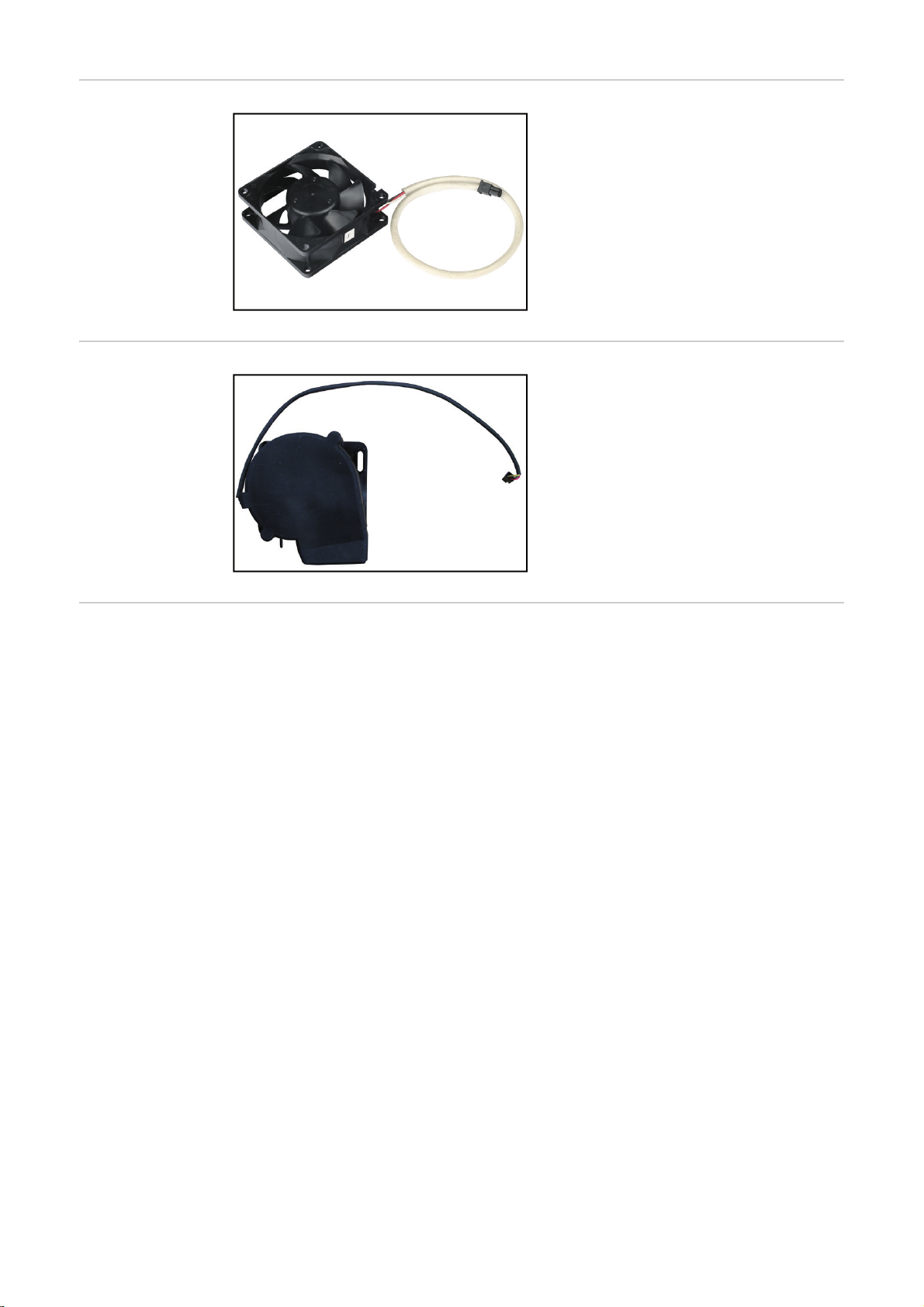
Lieferumfang Axiallüfter
Der Lieferumfang enthält:
- einen Axiallüfter
- inkl. Anschlusskabel
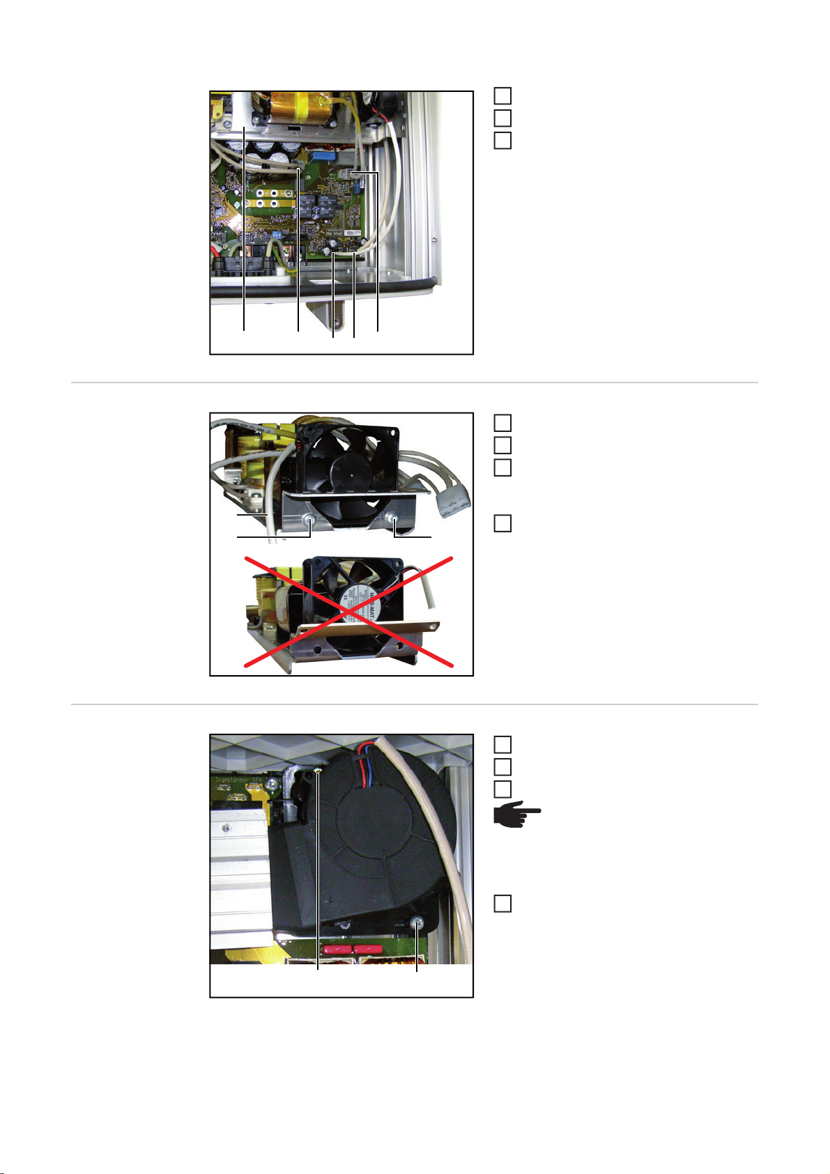
Lieferumfang Radiallüfter
Erforderliches
Werkzeug
Der Lieferumfang enthält:
- einen Radiallüfter
- inkl. Anschlusskabel
- Torx Schraubendreher TX 20
- Torx Schraubendreher TX 25
- Hand Drehmoment-Schrauber mit Bit-Einsatz TX 20 / 25
2
Page 5

Lüfter wechseln
1
5
(2)
(2)
(2)
(2)
DE
IG Plus öffnen
WARNUNG! Ein elektrischer Schlag kann tödlich sein. Gefahr durch Netzspan-
nung und DC-Spannung von den Solarmodulen. Vor sämtlichen Arbeiten am
Wechselrichter dafür sorgen, dass AC- und DC-Seite spannungsfrei sind.
Falls vorhanden, externen AC- und
DC-Trenner ausschalten und gegen
unbeabsichtigtes Wiedereinschalten
sichern
AC-Seite spannungsfrei schalten
2
DC Hauptschalter ausschalten
3
DC Hauptschalter gegen Wiederein-
4
schalten sichern
Seitliche Schrauben TX 25 (1) am
Leistungsteil lösen
Deckel vom Leistungsteil öffnen
(1) (1)
6
4 Schrauben TX 25 (2) lösen
7
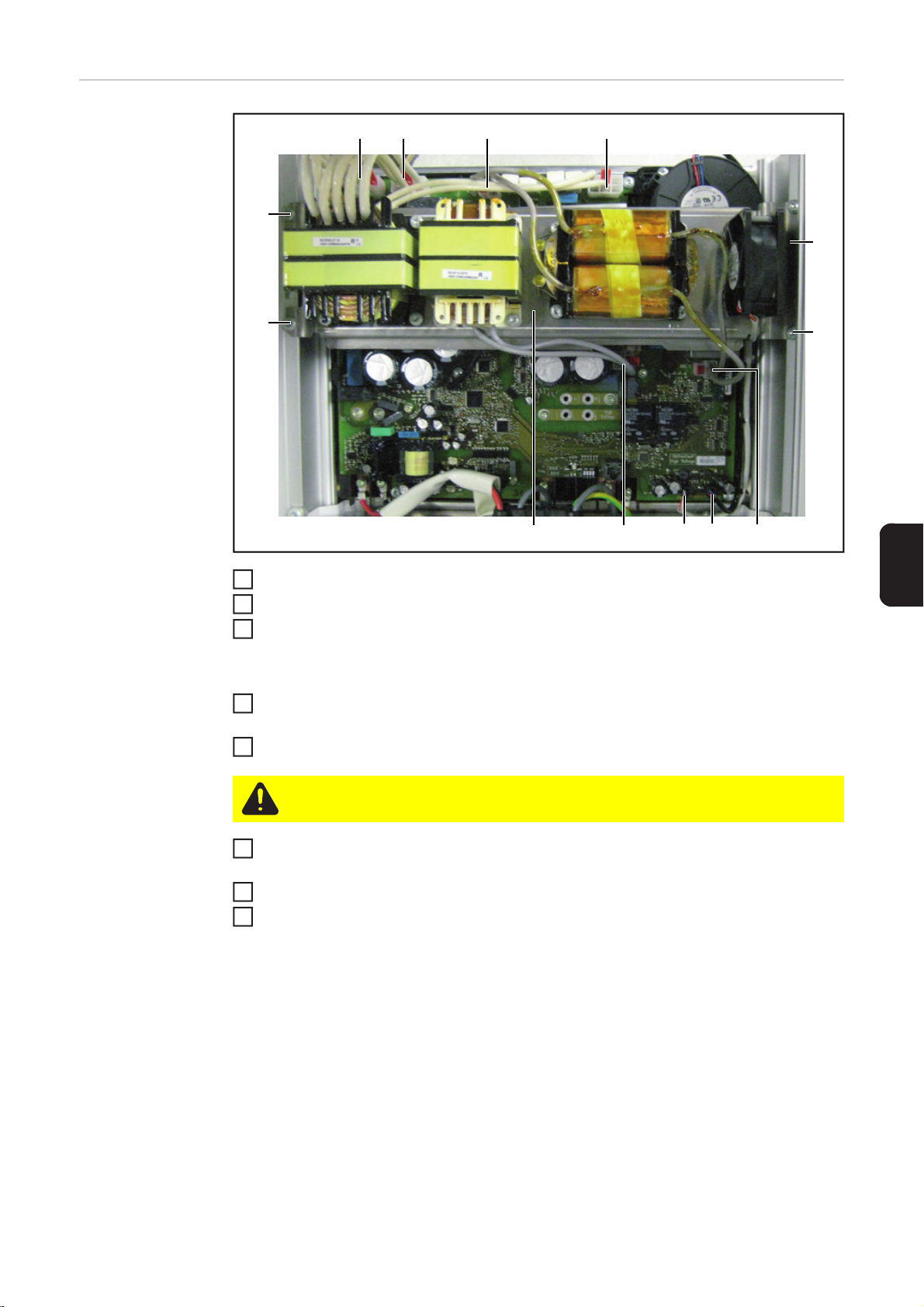
Vorbereitung
(2) (3) (4)
(1)
4 Stecker (1, 2, 3, 4) abstecken
1
3
Page 6

2 Stecker (6, 9) abstecken
2
4
2
Lüfterkabel (7, 8) abstecken
3
Induktivitätsbrücke (5) herausnehmen
4
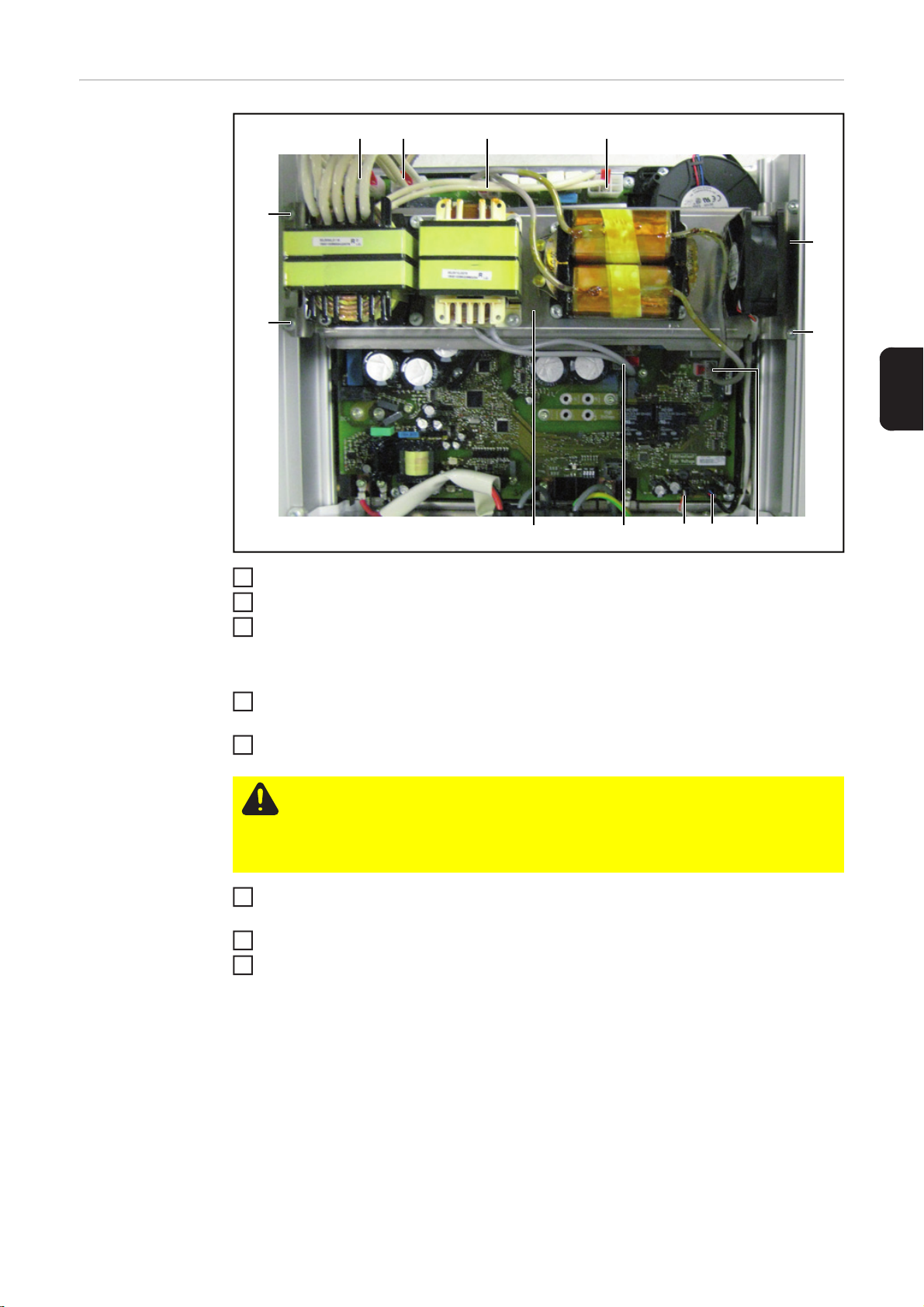
Axiallüfter wechseln
Radiallüfter
wechseln
(5) (6)
(2)
(7) (8)
(9)
2 Schrauben TX 25 (1) lösen
1
Lüfter herausnehmen
2
Neuen Lüfter so einsetzen das sich
3
das Anschlusskabel (2) auf der dargestellten Seite befindet
Lüfter mit 2 Schrauben TX 25 (1) be-
(1)(1)
4
festigen
Anzugsmoment: 0,8 Nm / 0.6 ft lb.
2 Schrauben (1) lösen
1
Lüfter herausnehmen
Neuen Lüfter einsetzen
3
HINWEIS! Beim Befestigen des
Lüfters darauf achten, dass die
Gummidichtung am Kühlkörper
anliegt.
WICHTIG! Das Lüfterkabel nicht zwischen
Lüfter und Gehäuse einklemmen.
Lüfter mit 2 Schrauben (1) befestigen
Anzugsmoment: 3 Nm / 2.2 ft lb.
(1)(1)
4
Page 7

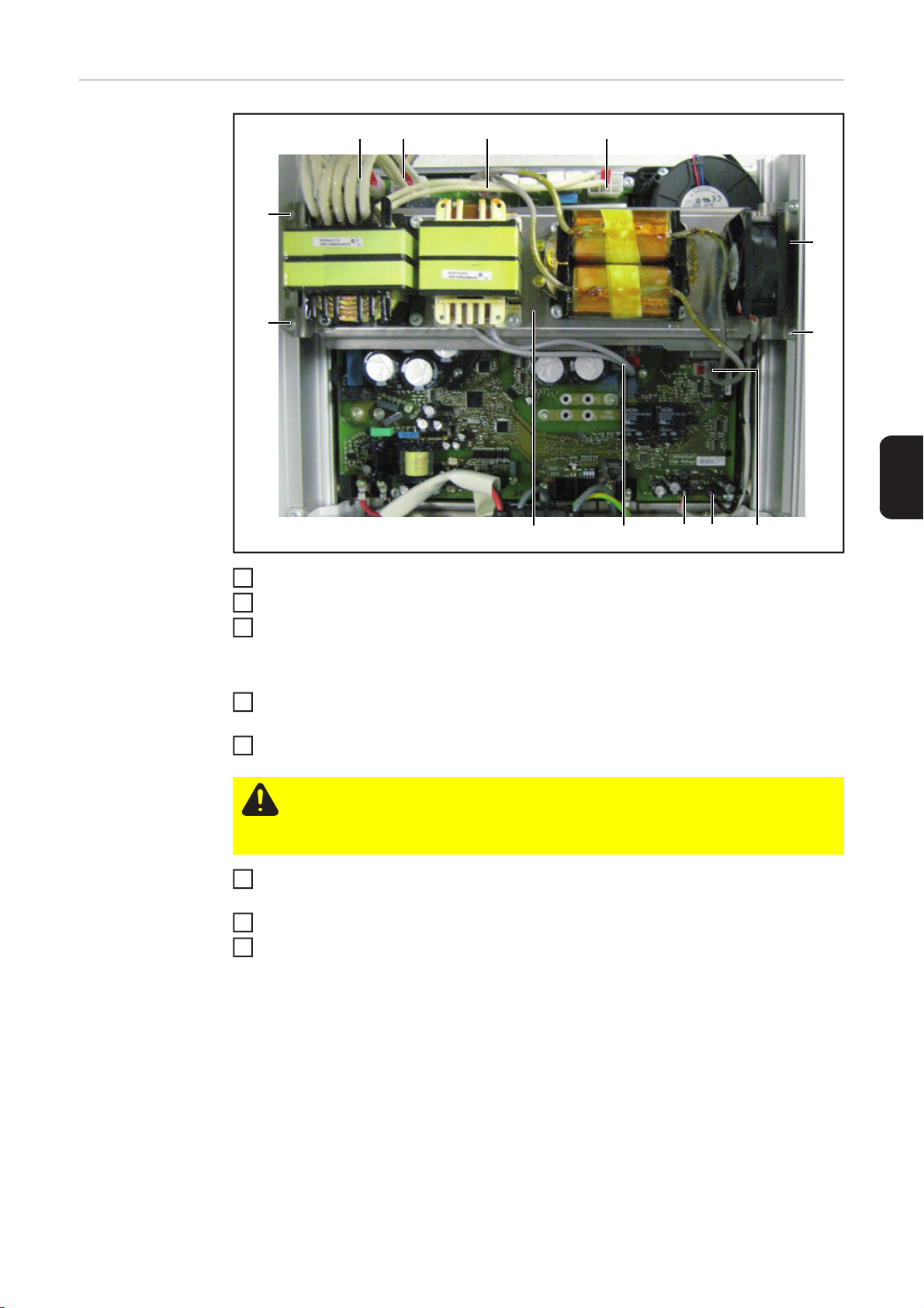
Abschließende
(2) (3) (4) (5)(1)
(9) (8) (7) (6)
(10)
(10)
(10)
(10)
1
7
Tätigkeiten
DE
Induktivitätenbrücke (1) einsetzen
Lüfterkabel (3, 4) anstecken
2
6 Kabel (2, 5, 6, 7, 8, 9) anstecken
3
WICHTIG! Lüfterkabel in der Führung auf der rechten Seite verlegen.
Induktivitätenbrücke (1) mit 4 Schrauben TX 25 (10) befestigen
4
Anzugsmoment: 3 Nm / 2.2 ft lb.
Deckel des Leistungsteiles schließen
5
VORSICHT! Unzureichende Schutzleiter-Verbindung kann schwerwiegende
Personen- und Sachschäden verursachen. Die Gehäuse-Schrauben stellen eine
geeignete Schutzleiter-Verbindung für die Erdung des Gehäuses dar und dürfen
keinesfalls durch andere Schrauben ohne zuverlässige Schutzleiter-Verbindung
ersetzt werden.
Deckel mittels seitlicher Schrauben TX 25 am Leistungsteil befestigen
6
Anzugsmoment: 3 Nm / 2.2 ft lb.
DC Hauptschalter einschalten
Falls vorhanden, externen AC- und DC-Trenner einschalten
8
5
Page 8

6
Page 9

General
Safety
WARNING! An electric shock can be fatal. Danger from grid voltage and DC volt-
age from solar modules.
- The connection area should only be opened by a licensed electrician.
- The separate power stage set area should only be disconnected from the
connection area after first being disconnected from the grid power.
- The separate power stage set area should only be opened by Fronius-trained
service technicians.
- Never work with live wires! Before any connection work, make sure that the
inverter's AC and DC wires are not charged.
- In the USA, all electrical installations must be in accordance with the National
Electrical Code, ANSI/NFPA 70, and any other codes and regulations applicable to the installation site.
- Installations in Canada must comply with the applicable Canadian standards.
Never work with live wires! Before any connection work, make sure that the inverter's AC and DC wires are not charged.
WARNING! An electric shock can be fatal. Danger from residual voltage from capacitors.
You must wait until the capacitors have discharged. Discharge takes 5 minutes.
Use a suitable measuring tool to ensure that the capacitors are discharged.
WARNING! Incorrect operation and work performed incorrectly can cause serious injury and damage! Only qualified staff are authorized to install your inverter
and only within the scope of the respective technical regulations. It is essential
that you read the "Safety regulations" chapter before commissioning the equipment or carrying out service or maintenance work.
EN-US
ESD Guidelines
NOTE! Requirements for electrical installations may be subject to national stan-
dards and regulations, and these must be followed accordingly.
NOTE! Observe ESD guidelines when handling electronic components and PC
boards. This primarily applies to ESD-compatible
- Packaging
- Work surfaces
-Floors
-Seating
- Grounding options
- Handling
No guarantee or warranty claims can be made in respect of any improperly handled electronic component or PC board.
7
Page 10

Axial Fan: Scope
of Supply
The scope of supply includes:
- an axial fan
- incl. connection cable
Radial Fan:
Scope of Supply
Required tools - TX 20 Torx screwdriver
- TX 25 Torx screwdriver
- Hand torque wrench with TX 20/25 bit insert
The scope of supply includes:
- a radial fan
- incl. connection cable
8
Page 11

Replacing fans
1
5
(2)
(2)
(2)
(2)
Opening IG Plus
WARNING! An electric shock can be fatal. Danger from grid voltage and DC volt-
age from solar modules. Never work with live wires! Make sure that the AC and
DC wires are not charged before you start work on the inverter.
If present, switch off the external AC
and DC disconnect and lock it off to
avoid inadvertent operation.
Disconnect power to the AC side
2
Turn off the main DC switch.
3
Secure DC main switch from being tur-
4
ned back on
Remove TX 25 side screws (1) from
the power stage set
Open power stage set cover
6
(1) (1)
Remove 4 TX 25 screws (2)
7
EN-US
Preparation
(2) (3) (4)
(1)
Disconnect 4 plugs (1, 2, 3, 4)
1
9
Page 12
Disconnect 2 plugs (6, 9)
2
4
2
Disconnect the fan cable (7, 8)
3
Remove inductance bridge (5)
4
Replacing the Axial Fan
Replacing the Radial Fan
(5) (6)
(2)
(7) (8)
(9)
Remove 2 TX 25 screws (1)
1
Remove fan
2
Insert the new fan so that the connec-
3
tion cable (2) is positioned on the side
shown.
Secure fan with 2 TX 25 screws (1)
(1)(1)
4
tightening torque: 0.8 Nm / 0.6 ft lb.
Remove 2 screws (1)
1
Remove fan
Insert new fan
3
NOTE! When securing the fan,
make sure that the rubber gasket
is up against the heat sink.
IMPORTANT! Do not pinch the fan cable
between the fan and the housing.
Secure fan with 2 screws (1)
tightening torque: 3 Nm / 2.2 ft lb.
(1)(1)
10
Page 13

Finally...
(2) (3) (4) (5)(1)
(9) (8) (7) (6)
(10)
(10)
(10)
(10)
1
7
EN-US
Insert the inductance bridge (1)
Connect fan cable (3, 4)
2
Connect 6 cables (2, 5, 6, 7, 8, and 9)
3
IMPORTANT! Neatly run the fan cables in the guide on the right side.
Secure inductance bridge (1) with 4 TX 25 screws (10)
4
tightening torque: 3 Nm / 2.2 ft lb.
Close power stage set cover
5
CAUTION! An inadequate grounding conductor connection can cause serious injuries to persons and damage to (or loss of) property. The housing screws provide
an adequate grounding conductor connection for the housing ground and should
not be replaced under any circumstances by other screws that do not provide a
proper grounding conductor connection.
Secure cover to the power stage set with TX 25 side screws
6
tightening toque 3 Nm / 2.2 ft lb.
Turn on DC main switch
If available, turn on the external AC and DC disconnecter
8
11
Page 14

12
Page 15

Generalidades
Seguridad
¡ADVERTENCIA! Las descargas eléctricas pueden ser mortales. Peligro origina-
do por la tensión de red y la tensión DC de los módulos solares.
- Solo instaladores eléctricos oficiales deben abrir la zona de conexión.
- La zona separada de las etapas de potencia solo se puede separar de la
zona de conexión cuando no tiene tensión.
- Solo personal de servicio formado por Fronius debe abrir la zona separada
de las etapas de potencia.
- Antes de realizar cualquier tipo de trabajo de conexión se debe procurar que
los lados AC y DC delante del inversor no tengan tensión.
- En EE. UU. deben realizarse todas las conexiones eléctricas según el National Electrical Code ANSI/NFPA 70 y las demás directivas vigentes en el lugar de instalación.
- Las instalaciones en Canadá deben realizarse según las normas canadienses vigentes.
Antes de realizar cualquier tipo de trabajo de conexión se debe procurar que los
lados AC y DC delante del inversor no tengan tensión.
¡ADVERTENCIA! Las descargas eléctricas pueden ser mortales. Peligro originado por la tensión residual de los condensadores.
Esperar hasta que se descarguen los condensadores. El tiempo de descarga es
de 5 minutos.
Con la ayuda de un medidor adecuado, asegurarse de que los condensadores
están descargados.
ES
Disposiciones
ESD
¡ADVERTENCIA! El manejo incorrecto y los trabajos realizados de forma defec-
tuosa pueden causar graves daños personales y materiales. La puesta en servicio del inversor solo debe ser efectuada por personal formado y en el marco de
las disposiciones técnicas. Antes de la puesta en servicio y de la realización de
trabajos de servicio y reparación, resulta imprescindible leer el capítulo "Disposiciones de seguridad".
¡OBSERVACIÓN! Los requisitos para instalaciones eléctricas pueden estar sujetos a normas y disposiciones nacionales y deben ser cumplidos según las mismas.
¡OBSERVACIÓN! Observar las disposiciones ESD para manipular los circuitos
impresos y componentes electrónicos. Estas incluyen sobre todo elementos que
cumplen las disposiciones ESD como
- Embalajes
- Superficies de trabajo
-Suelos
- Asientos
- Posibilidades de puesta a tierra
- Manipulación
No se pueden reclamar derechos de garantía por un componente electrónico o un circuito
impreso que no haya sido tratado debidamente.
13
Page 16

Volumen de suministro para el ventilador axial
El volumen de suministro incluye lo siguiente:
- Un ventilador axial
- Cable de conexión
Volumen de suministro para el ventilador radial
Herramientas necesarias
El volumen de suministro incluye lo siguiente:
- Un ventilador radial
- Cable de conexión
- Destornillador Torx TX 20
- Destornillador Torx TX 25
- Atornillador de par manual con inserto bit TX 20 / 25
14
Page 17

Cambiar el ventilador
1
5
(2)
(2)
(2)
(2)
Abrir el IG Plus
¡ADVERTENCIA! Las descargas eléctricas pueden ser mortales. Peligro origina-
do por la tensión de red y la tensión DC de los módulos solares. Antes de realizar
cualquier tipo de trabajo en el inversor se debe procurar que los lados AC y DC
no tengan tensión.
Si estuviera disponible, desconectar el
seccionador AC y DC externo y asegurarlo contra cualquier reconexión
accidental.
Conmutar el lado AC sin tensión.
2
Desconectar el interruptor principal
3
DC.
Asegurar el interruptor principal DC
4
contra cualquier reconexión.
Soltar los tornillos laterales TX 25 (1)
en la etapa de potencia
(1) (1)
Abrir la tapa de la etapa de potencia.
6
Soltar los 4 tornillos TX 25 (2).
7
ES
15
Page 18

Preparación
(1)
(2) (3) (4)
Desenchufar las 4 clavijas (1, 2, 3, 4).
1
Desenchufar las 2 clavijas (6, 9).
2
Desenchufar el cable de ventilador (7,
3
8).
Sacar el puente de inductividad (5).
4
Cambiar el ventilador axial
(5) (6)
(2)
(7) (8)
(9)
Soltar los 2 tornillos TX 25 (1).
1
Extraer el ventilador.
2
Colocar el ventilador nuevo de tal
3
modo que el cable de conexión (2) se
encuentre en el lado mostrado.
Fijar el ventilador con los 2 tornillos TX
(1)(1)
4
25 (1).
Par de apriete: 0,8 Nm / 0.6 ft lb.
16
Page 19

Cambiar el venti-
2
4
(2) (3) (4) (5)(1)
(9) (8) (7) (6)
(10)
(10)
(10)
(10)
3
lador radial
Actividades finales
Soltar los 2 tornillos (1)
1
Extraer el ventilador.
Colocar el ventilador nuevo.
3
¡OBSERVACIÓN! Al fijar el ventilador, prestar atención a que la
junta de goma se encuentre en
contacto con el disipador de calor.
¡IMPORTANTE! No aplastar el cable de
ventilador entre el ventilador y la caja.
Fijar el ventilador con los 2 tornillos (1).
Par de apriete: 3 Nm / 2.2 ft lb.
ES
(1)(1)
Colocar el puente de inductividad (1).
1
Enchufar los cables de ventilador (3, 4).
2
Enchufar los 6 cables (2, 5, 6, 7, 8, 9).
¡IMPORTANTE! Instalar el cable de ventilador en la guía del lado derecho.
Fijar el puente de inductividad (1) con los 4 tornillos TX 25 (10).
4
Par de apriete: 3 Nm / 2.2 ft lb.
Cerrar la tapa de la etapa de potencia.
5
17
Page 20

¡PRECAUCIÓN! Una conexión inapropiada del conductor de protección puede
causar graves daños personales y materiales. Los tornillos de la caja del aparato
constituyen una conexión adecuada del conductor de protección para la puesta
a tierra de la caja y nunca deben ser sustituidos por otros tornillos sin una conducción del conductor de protección fiable.
Fijar la tapa en la etapa de potencia utilizando los tornillos laterales TX 25.
6
Par de apriete: 3 Nm / 2.2 ft lb.
Conectar el interruptor principal DC.
7
Conectar el seccionador AC y DC externo si estuviera disponible.
8
18
Page 21

Généralités
Sécurité
AVERTISSEMENT ! Une décharge électrique peut être mortelle. Danger en rai-
son de la tension du secteur et de la tension DC des modules solaires.
- Seuls des installateurs agréés sont habilités à ouvrir la zone de raccordement.
- Le bloc indépendant des étages de puissance ne doit être séparé de la zone
de raccordement que si l'ensemble est hors tension.
- Seuls des installateurs formés par Fronius sont habilités à ouvrir le bloc indépendant des étages de puissance.
- Avant toute opération de raccordement, veiller à ce que les côtés AC et DC
avant l'onduleur soient hors tension.
- Aux USA, toutes les connexions électriques doivent être réalisées conformément aux prescriptions du National Electrical Code ANSI/NFPA 70 et aux directives en vigueur sur le site de l'installation.
- Les installations au Canada doivent être réalisées conformément aux normes canadiennes en vigueur.
Avant toute opération de raccordement, veiller à ce que les côtés AC et DC avant
l'onduleur soient hors tension.
AVERTISSEMENT ! Une décharge électrique peut être mortelle. Risque dû à la
tension résiduelle de condensateurs.
Attendre l'expiration de la durée de décharge des condensateurs. Cette durée
correspond à 5 minutes
S'assurer, à l'aide d'un appareil de mesure approprié, que les condensateurs sont
déchargés.
FR
Directives relatives aux décharges
électrostatiques
AVERTISSEMENT ! Les erreurs de commande et les erreurs en cours d'opéra-
tion peuvent entraîner des dommages corporels et matériels graves. La mise en
service de l'onduleur ne peut être effectuée que par du personnel formé à cet effet
et dans le cadre des directives techniques. Avant la mise en service et l'exécution
de travaux de service et de réparation, lire impérativement le chapitre « Consignes de sécurité ».
REMARQUE! Les exigences fixées pour les installations électriques peuvent
être soumises à des normes et des directives nationales qui doivent être respectées de manière correspondante.
REMARQUE! Respectez les directives relatives aux décharges électrostatiques
lors de la manipulation des composants électroniques et circuits imprimés. Les
éléments suivants doivent être adaptés aux décharges électrostatiques :
- Emballages
- Plans de travail
-Sols
-Sièges
- Possibilités de mise à la terre
- Manipulation
La garantie ne couvre pas les composants électroniques et circuits imprimés utilisés de
manière non conforme aux instructions.
19
Page 22

Livraison du ventilateur axial
La livraison comprend :
- un ventilateur axial
- avec câble de connexion
Livraison du ventilateur radial
Outils requis - Tournevis Torx TX 20
- Tournevis Torx TX 25
- Clé dynamométrique manuelle avec embout TX 20 / 25
La livraison comprend :
- un ventilateur radial
- avec câble de connexion
20
Page 23

Remplacer le ventilateur
1
5
(2)
(2)
(2)
(2)
Ouvrir le Fronius
IG Plus
AVERTISSEMENT ! Une décharge électrique peut être mortelle. Danger en rai-
son de la tension du secteur et de la tension DC des modules solaires. Avant toute opération sur l'onduleur, veiller à ce que les côtés AC et DC soient hors tension.
S'ils existent, déconnecter les sectionneurs externes AC et DC et sécuriser
contre toute remise en marche intempestive
Raccorder le côté AC hors tension
2
Déconnecter l'interrupteur principal DC
3
Sécuriser l'interrupteur principal DC
4
contre tout risque de reconnexion
Desserrer les vis TX 25 (1) de l'étage
de puissance
Ouvrir le couvercle de l'étage de puis-
(1) (1)
6
sance
Desserrer les 4 vis TX 25 (2)
7
FR
Préparation
(2) (3) (4)
(1)
Débrancher les 4 fiches (1, 2, 3, 4)
1
21
Page 24

Débrancher les 2 fiches (6, 9)
2
4
2
Débrancher le câble de ventilateur (7,
3
8)
Sortir le pont de Maxwell (5)
4
Remplacer le ventilateur axial
Remplacer le ventilateur radial
(5) (6)
(2)
(7) (8)
(9)
Desserrer les 2 vis TX 25 (1)
1
Retirer le ventilateur
2
Installer le nouveau ventilateur de ma-
3
nière à ce que le câble de connexion
(2) se trouve sur le côté présenté sur
l'illustration
(1)(1)
Fixer le ventilateur avec 2 vis TX 25 (1)
4
Couple de serrage : 0,8 Nm / 0.6 ft lb.
Desserrer les 2 vis (1)
1
Retirer le ventilateur
Mettre en place le ventilateur neuf
3
REMARQUE! Lors de la fixation
du ventilateur, veiller à ce que le
joint caoutchouc repose bien
contre le dissipateur thermique.
IMPORTANT! Ne pas coincer le câble du
ventilateur entre le ventilateur et le boîtier.
Fixer le ventilateur avec les 2 vis (1)
Couple de serrage : 3 Nm / 2.2 ft lb.
(1)(1)
22
Page 25
Opérations fina-
(2) (3) (4) (5)(1)
(9) (8) (7) (6)
(10)
(10)
(10)
(10)
1
7
les
FR
Mettre en place le pont de Maxwell (1)
Brancher les câbles du ventilateur (3, 4)
2
Brancher les 6 câbles (2, 5, 6, 7, 8, 9)
3
IMPORTANT! Poser le câble de ventilateur dans la coulisse sur le côté droit.
Fixer le pont de Maxwell (1) avec 4 vis TX 25 (10)
4
Couple de serrage : 3 Nm / 2.2 ft lb.
Fermer le couvercle de l'étage de puissance
5
ATTENTION ! Une connexion insuffisante à la terre peut entraîner de graves
dommages corporels et matériels. Les vis du carter constituent une connexion de
terre appropriée pour la mise à la terre du carter de l’appareil et ne doivent en
aucun cas être remplacées par d’autres vis qui n’offriraient pas ce type de
connexion fiable de la terre.
Fixer le couvercle sur l'étage de puissance avec les vis latérales TX 25
6
Couple de serrage : 3 Nm / 2.2 ft lb.
Connecter l'interrupteur principal DC
S'ils existent, connecter les sectionneurs externes AC et DC
8
23
Page 26

24
Page 27

In generale
Sicurezza
AVVISO! Una scossa elettrica può risultare mortale. Pericolo derivante dalla ten-
sione di rete e dalla tensione CC dei moduli solari.
- La scatola dei collegamenti deve essere aperta solo da installatori elettrici
qualificati.
- La scatola separata delle fonti d'energia deve essere staccata dalla scatola
dei collegamenti solo in assenza di tensione.
- La scatola separata delle fonti d'energia deve essere aperta solo da personale qualificato dell'assistenza Fronius.
- Prima di eseguire qualsiasi collegamento, togliere la tensione dal lato CA e
CC dell'inverter.
- Negli Stati Uniti tutti i collegamenti elettrici devono essere eseguiti conformemente al National Electrical Code ANSI/NFPA 70 e alle altre direttive relative
al luogo di installazione vigenti.
- Le installazioni in Canada devono essere eseguite conformemente alle norme canadesi vigenti.
Prima di eseguire qualsiasi collegamento, togliere la tensione dal lato CA e CC
dell'inverter.
AVVISO! Una scossa elettrica può risultare mortale. Pericolo derivante dalla tensione residua dei condensatori.
Attendere il tempo di scaricamento dei condensatori (5 minuti).
Con l'ausilio di uno strumento di misura adatto, accertarsi che i condensatori siano scarichi.
IT
Disposizioni concernenti le scariche
elettrostatiche
AVVISO! L'utilizzo improprio e l'esecuzione errata degli interventi possono cau-
sare lesioni personali e danni materiali gravi. La messa in funzione dell'inverter
deve essere eseguita esclusivamente da personale addestrato e conformemente
alle disposizioni tecniche. È assolutamente necessario leggere il capitolo "Norme
di sicurezza" prima della messa in funzione e dell'esecuzione di interventi di assistenza, manutenzione e riparazione.
AVVERTENZA! I requisiti per le installazioni elettriche possono essere soggetti
alle norme e alle disposizioni nazionali. Le installazioni devono essere eseguite
conformemente a tali norme e disposizioni.
AVVERTENZA! Nel maneggiare i componenti elettronici e i print, attenersi alle disposizioni relative alle scariche elettrostatiche, che prevedono in particolare appositi
- imballaggi
- superfici di lavoro
-pavimenti
-piani
- opzioni per la messa a terra.
- Manipolazione
In caso di manipolazione non corretta di componenti elettronici o print, non è possibile far
valere alcun diritto di garanzia.
25
Page 28

Fornitura ventola
assiale
La fornitura comprende:
- una ventola assiale
- incl. cavo di collegamento.
Fornitura ventola
radiale
Attrezzi necessari - Cacciavite Torx TX 20
- Cacciavite Torx TX 25
- Giraviti dinamometrico manuale con inserto bit TX 20 / 25
La fornitura comprende:
- una ventola radiale
- incl. cavo di collegamento.
26
Page 29

Sostituzione della ventola
1
5
(2)
(2)
(2)
(2)
Apertura di IG
Plus
AVVISO! Una scossa elettrica può risultare mortale. Pericolo derivante dalla ten-
sione di rete e dalla tensione CC dei moduli solari. Prima di eseguire qualsiasi intervento sull'inverter, togliere la tensione dal lato CA e CC dell'inverter.
Se presenti, disattivare i sezionatori
CA e CC esterni e assicurarsi che non
vengano accidentalmente riattivati.
Togliere la tensione dal lato CA.
2
Spegnere l'interruttore principale CC.
3
Assicurarsi che l'interruttore principale
4
CC non venga riacceso.
Svitare le viti TX 25 (1) laterali della
fonte d'energia.
Aprire la copertura della fonte d'ener-
6
gia.
(1) (1)
Svitare le 4 viti TX 25 (2).
7
IT
Operazioni preliminari
(2) (3) (4)
(1)
Scollegare le 4 spine (1, 2, 3, 4).
1
27
Page 30

Scollegare le 2 spine (6, 9).
2
4
2
Scollegare il cavo della ventola (7, 8).
3
Estrarre il ponticello d'induttanza (5).
4
Sostituzione della
ventola assiale
Sostituzione della
ventola radiale
(5) (6)
(2)
(7) (8)
(9)
Svitare le 2 viti TX 25 (1).
1
Estrarre la ventola.
2
Installare la ventola nuova in modo che
3
il cavo di collegamento (2) si trovi sul
lato illustrato in figura.
Fissare la ventola con 2 viti TX 25 (1).
(1)(1)
4
Coppia di serraggio: 0,8 Nm / 0.6 ft lb.
Allentare le 2 viti (1).
1
Estrarre la ventola.
Installare la ventola nuova.
3
AVVERTENZA! Durante il fissaggio della ventola, assicurarsi che
la guarnizione in gomma aderisca
al raffreddatore.
IMPORTANTE! Non schiacciare il cavo
della ventola tra la ventola e il corpo esterno.
Fissare la ventola con 2 viti (1).
Coppia di serraggio: 3 Nm / 2.2 ft lb.
(1)(1)
28
Page 31
Operazioni con-
(2) (3) (4) (5)(1)
(9) (8) (7) (6)
(10)
(10)
(10)
(10)
1
7
clusive
IT
Installare il ponticello d'induttanza (1).
Collegare i cavi della ventola (3, 4).
2
Collegare i 6 cavi (2, 5, 6, 7, 8, 9).
3
IMPORTANTE! Far passare il cavo della ventola nella guida sul lato destro.
Fissare il ponticello d'induttanza (1) con 4 viti TX 25 (10).
4
Coppia di serraggio: 3 Nm / 2.2 ft lb.
Chiudere la copertura della fonte d'energia.
5
PRUDENZA! Un collegamento insufficiente con il conduttore di terra può causare
gravi lesioni personali e danni materiali. Le viti del corpo esterno rappresentano
una protezione adatta per la messa a terra del corpo esterno e non possono in
alcun caso essere sostituite da altre viti senza adeguata protezione.
Fissare la copertura sulla fonte d'energia con le viti TX 25 laterali.
6
Coppia di serraggio: 3 Nm / 2.2 ft lb.
Accendere l'interruttore principale CC.
Se presenti, attivare i sezionatori CA e CC esterni.
8
29
Page 32

30
Page 33

概述
安全
警告 ! 电击可能是致命的。电源电压和太阳能模块的 DC 电压会造成危险。
- 只允许由得到授权的电气安装工打开连接区。
- 功率部件的分离区只容许在无电压的状态下从连接区分开。
- 电源模块的分离区只能由 Fronius 经过培训的服务人员打开。
- 在所有连接作业开始之前确保,逆变器前的 AC 和 DC 侧是无电压的。
- 在美国,必须根据国家电气规范 (National Electrical Code) ANSI/NFPA 70
以及其他适用于安装位置的有效指令进行所有电气连接。
- 在加拿大,必须根据有效的加拿大标准进行安装。
在所有连接作业开始之前确保,逆变器前的 AC 和 DC 侧是无电压的。
警告 ! 电击可能是致命的。继电器剩余电压会造成危险。
等待继电器的放电时间。放电时间为 5 分钟。
借助合适的测量仪器确保电容器已放电。
警告 ! 错误操作和错误执行作业可能会造成严重的人身伤害和财产损失。逆变器
的试运转只允许由经过培训的人员在技术规定的框架范围内完成。在试运转和维
护及维修作业执行之前务必阅读 “ 安全规定 ” 这一章节。
注意 ! 电气安装要求服从国家标准和规定,必须遵照执行。
ZH
ESD 规定
轴向鼓风机供货范
围
注意 ! 在使用电子元件和电路板时,请遵守 ESD 规定。ESD 规定主要包括
-包装
-工作区
-地面
-底座
- 接地可能性
-操作
电子元件或电路板操作不当可能使质保和保修失效。
供货范围包括:
- 一个轴向鼓风机
- 包括连接电缆
31
Page 34

径向鼓风机供货范
围
所需工具 - Torx 螺丝刀 TX 20
- Torx 螺丝刀 TX 25
- 使用 TX 20 / 25 套件的手动扭力扳手
供货范围包括:
- 一个径向鼓风机
- 包括连接电缆
32
Page 35

更换鼓风机
5
打开 IG Plus
警告 ! 电击可能是致命的。电源电压和太阳能模块的 DC 电压会造成危险。在逆
变器上进行所有工作之前确保 AC 和 DC 侧无电压。
(1) (1)
(2)
(2)
如果有,关闭 AC 和 DC 分离器并防止
1
意外地再次接通
关闭 AC 侧
2
断开 DC 总开关
3
防止 DC 总开关再次接通
4
松开电源模块侧面的螺栓 TX 25 (1)
打开电源模块盖板
6
松开 4 根螺栓 TX 25 (2)
7
ZH
准备
(2)
(2) (3) (4)
(1)
(2)
拔下 4 个插头 (1,2,3,4)
1
33
Page 36

拔下鼓风机电缆 (7,8)
4
3
取出感应电桥 (5)
4
更换轴向鼓风机
(5) (6)
拔下 2 个插头 (6,9)
2
(2)
(7) (8)
(9)
松开 2 根螺栓 TX 25 (1)
1
取出鼓风机
2
装入新的鼓风机,确保连接电缆 (2)
3
位于图示侧
用 2 根螺栓 TX 25 (1) 固定鼓风机
4
拧紧力矩:0.8 Nm / 0.6 ft lb.
(1)(1)
更换径向鼓风机
34
松开 2 根螺栓 (1)
1
取出鼓风机
2
插入新的鼓风机
3
注意 ! 固定鼓风机时注意,应将
橡胶垫紧贴在散热器上。
重要 ! 鼓风机电缆不能夹在鼓风机与外壳
之间。
用 2 根螺栓 (1) 固定鼓风机,
拧紧力矩:3 Nm / 2.2 ft lb.
(1)(1)
Page 37
接下来的工作
(2) (3) (4) (5)(1)
(9) (8) (7) (6)
(10)
(10)
(10)
(10)
2
4
5
置入感应电桥 (1)
1
插入鼓风机电缆 (3,4)
插入 6 根电缆 (2,5,6,7,8,9)
3
重要 ! 将鼓风机电缆引入右侧敷设。
使用 4 根螺栓 TX 25 (10) 固定感应电桥 (1)
拧紧力矩:3 Nm / 2.2 ft lb.
关闭电源模块的盖板
小心 ! 接地不充分可能会造成严重的人身伤害和财产损失。外壳螺栓起到外壳接
地的作用,切勿使用不能保证接地的其他螺栓。
借助侧面螺栓 TX 25 将盖板固定在电源模块上
6
拧紧力矩:3 Nm / 2.2 ft lb.
接通 DC 总开关
7
如果有,接通外部 AC 和 DC 分离器
8
ZH
35
Page 38

36
Page 39

37
Page 40

Fronius Worldwide - www.fronius.com/addresses
Fronius International GmbH
4600 Wels, Froniusplatz 1, Austria
E-Mail: pv@fronius.com
http://www.fronius.com
Under http://www.fronius.com/addresses you will find all addresses of our sales branches and partner firms!
Fronius USA LLC Solar Electronics Division
10421 Citation Drive, Suite 1100, Brighton, MI 48116
E-Mail: pv-us@fronius.com
http://www.fronius-usa.com
 Loading...