


Operating
www.youtube.com/FroniusSolar
LEARN MORE WITH
OUR HOW-TO VIDEOS
Instructions
Fronius Energy Package
Operating Instructions
EN
42,0426,0222,EN 024-14042023


Contents
Safety rules 7
Explanation of safety notices 7
General 7
Environmental conditions 8
Qualified personnel 8
Noise emission values 8
EMC measures 8
Emergency power 9
Copyright 9
Data protection 9
General information 11
Fronius Symo Hybrid 13
Device concept 13
Proper use 14
Warning notices on the device 14
Product registration 15
Fronius Solar Battery 17
Device concept 17
Proper use 17
Increase in storage capacity 18
State of charge (SOC) accuracy 18
Warning notices on the device 18
The various operating modes 20
Operating modes – Explanation of symbols 20
Operating mode: Inverter 20
Operating mode - Inverter plus battery 21
Operating mode - Inverter plus battery and multiple Smart Meters 22
Operating mode - inverter with battery, AC-coupled to another inverter 22
Operating mode - Inverter plus battery and emergency power function 22
Operating mode - Inverter plus battery, Ohmpilot and emergency power function 23
Operating mode - Inverter plus battery, additional inverter and emergency power function 24
Operating states (only for systems with a battery) 24
Emergency power mode 26
Prerequisites for emergency power mode 26
Transitioning from feeding energy into the grid to backup power mode 26
Transitioning from backup power mode to feeding energy into the grid 26
Restrictions in backup power mode 27
Backup power and energy saving mode 27
Fronius Ohmpilot and backup power mode 27
Energy saving mode 29
General 29
Fronius Solar Battery and Fronius Symo Hybrid switch-off conditions 29
Fronius Symo Hybrid and Fronius Solar Battery switch-on conditions 30
Special case 30
Indicators on the devices and user interfaces 30
Calibration charging for the Fronius Solar Battery 31
Benefits of calibration charging 31
General 31
Conditions for starting the calibration charge (Fronius Solar Battery) 31
Calibration charging procedure (Fronius Solar Battery) 31
Calibration process (Fronius Solar Battery) 32
Duration of calibration charging (Fronius Solar Battery) 32
Limitations during calibration (Fronius Solar Battery) 32
Display during calibration charge (Fronius Solar Battery) 32
Suitable third-party batteries for Fronius Symo Hybrid 34
LG Chem ResuH 34
BYD Battery-Box Premium 34
EN
3

Operation 37
Data communication 39
Data communication area 39
General 39
Controls, connections and indicators on the system monitoring unit 40
Fronius Hybrid inverter 44
Controls and indicators 44
Display 45
Fronius Solar Battery 46
Battery management module 46
Battery module 46
Display 46
Display types 47
Data converter connections 50
Data converter controls and indicators 50
Data converter LED displays 50
Navigation at the menu level 52
Activating display backlighting 52
Automatic deactivation of display backlighting / changing to the "NOW" menu item 52
Opening the menu level 52
Values displayed under the NOW menu item 53
Values displayed under the LOG menu item 53
Menu items in the Set-up menu 54
Standby 54
WiFi Access Point 54
Relay (floating contact switch) 55
Energy Manager(under "Relay" menu item) 56
Time / Date 57
Display settings 58
ENERGY YIELD 58
Fan 59
SETUP menu item 60
Initial setting 60
Software updates 60
Navigating the SETUP menu item 60
Setting menu entries, general 61
Application example: Setting the time 61
The INFO menu item 63
Measured values 63
PSS status 63
Grid status 63
Device information 63
Version 65
Switching the key lock on and off 66
General 66
Switching the key lock on and off 66
The Basic menu 67
Access the Basic menu 67
Items on the Basic menu 67
Fronius system monitoring 69
General 71
General 71
Prerequisites for operation 71
Calculating data volumes 72
General 72
Calculating data volumes 72
General information for the network administrator 74
Requirements 74
General firewall settings 74
4

Using Fronius Solar.web and sending service messages 75
Installing Fronius system monitoring – Overview 76
Safety 76
Starting for the first time 76
Information to help you work through the technician wizard 78
Testing backup power mode 79
Connecting to Fronius system monitoring via a web browser 80
General remarks 80
Prerequisites 80
Establishing a connection to Fronius system monitoring via a web browser 80
Connecting to Fronius system monitoring established via the Internet and Fronius Solar.web 81
General remarks 81
Functional description 81
Prerequisites 81
Accessing Fronius system monitoring data via the Internet and Fronius Solar.web 81
Current data, services and settings offered by Fronius system monitoring 83
The Fronius system monitoring web page 85
Fronius system monitoring web page – Overview 85
The Settings menu 85
Additional setting options 86
Services – System information 87
System information 87
Services – Network diagnostics 88
Network diagnostics 88
Services – Firmware update 89
General 89
Searching for updates automatically 89
Searching for updates manually 89
Updating the firmware via the Web 89
Services – Starting the wizard 90
Starting the wizard 90
Settings – General 91
General 91
Settings – Passwords 92
General remarks 92
Passwords 92
Settings – Network 93
Internet via WLAN 93
Internet via LAN 93
Local network via access point 93
Settings – Fronius Solar.web 95
Fronius Solar.web 95
Settings – IO mapping 96
General 96
Emergency power 96
Load management 96
IO control 96
AUS - Demand Response Modes (DRM) 96
Energy storage device 98
Settings - load management 99
Load management 99
Settings – Push Service 100
Push Service 100
Settings – Modbus 101
General remarks 101
Further information about the Modbus function 101
Exporting data via Modbus 101
Restricting control 102
Settings – Energy Manager 103
Energy management 103
Energy management examples 103
EN
5

Battery management 106
Permitted battery control parameters 107
PV power reduction 109
Settings – System overview 111
System overview 111
Settings - Meter 113
General 113
Fronius Smart Meter 113
Connection of the Fronius Smart Meter to Fronius system monitoring 113
Settings – DNO Editor 115
General 115
DNO Editor – IO control 115
Connection example 115
"PSC editor - AUS - Demand Response Modes (DRM)" 116
DNO Editor – Dynamic power reduction 116
DNO Editor – Control priorities 117
DNO Editor – Battery charge 118
Dynamic power regulation with several inverters 118
Settings – Battery 120
Battery 120
Troubleshooting and maintenance 121
Fronius Symo Hybrid 123
Status code display 123
Total failure of the display 123
Status codes – Class 1 123
Status codes – Class 3 124
Status codes – Class 4 125
Status codes – Class 5 127
Status codes – Class 6 129
Status codes – Class 7 129
Status codes – Class 9 130
Class 10 - 12 status codes 132
Customer service 132
Operation in dusty environments 132
Fronius Solar Battery 133
Status code display 133
Error messages – Battery management module 133
Error message – Data converter 133
Undefined operating statuses 134
Appendix 137
Technical data 139
System monitoring 141
Explanation of footnotes 142
Applicable standards and guidelines 142
Warranty terms and conditions, and disposal 144
Fronius manufacturer's warranty 144
Disposal 144
6

Safety rules
EN
Explanation of
safety notices
DANGER!
Indicates immediate danger.
If not avoided, death or serious injury will result.
▶
WARNING!
Indicates a potentially hazardous situation.
If not avoided, death or serious injury may result.
▶
CAUTION!
Indicates a situation where damage or injury could occur.
If not avoided, minor injury and/or damage to property may result.
▶
NOTE!
Indicates a risk of flawed results and possible damage to the equipment.
General The device has been manufactured in line with the state of the art and according
to recognized safety standards. If used incorrectly or misused, however, it can
cause:
Injury or death to the operator or a third party
-
Damage to the device and other material assets belonging to the operating
-
company.
All personnel involved in commissioning, maintenance, and servicing of the
device must:
Be suitably qualified
-
Have knowledge of and experience in dealing with electrical installations and
-
Have fully read and precisely followed these Operating Instructions
-
The Operating Instructions must always be at hand wherever the device is being
used. In addition to the Operating Instructions, attention must also be paid to
any generally applicable and local regulations regarding accident prevention and
environmental protection.
All safety and danger notices on the device:
Must be kept in a legible state
-
Must not be damaged
-
Must not be removed
-
Must not be covered, pasted or painted over
-
The terminals can reach high temperatures.
Only operate the device when all protection devices are fully functional. If the
protection devices are not fully functional, there is a danger of:
Injury or death to the operator or a third party
-
Damage to the device and other material assets belonging to the operating
-
company
7

Any safety devices that are not fully functional must be repaired by an authorised specialist before the device is switched on.
Never bypass or disable protection devices.
For the location of the safety and danger notices on the device, refer to the section headed "General remarks" in the Operating Instructions for the device.
Any equipment malfunctions which might impair safety must be remedied before
the device is turned on.
This is for your personal safety!
Environmental
conditions
Qualified personnel
Operation or storage of the device outside the stipulated area will be deemed as
not in accordance with the intended purpose. The manufacturer accepts no liability for any damage resulting from improper use.
The servicing information contained in these operating instructions is intended
only for the use of qualified service engineers. An electric shock can be fatal. Do
not carry out any actions other than those described in the documentation. This
also applies to qualified personnel.
All cables and leads must be secured, undamaged, insulated and adequately dimensioned. Loose connections, scorched, damaged or inadequately dimensioned
cables and leads must be immediately repaired by authorised personnel.
Maintenance and repair work must only be carried out by an authorised specialist.
It is impossible to guarantee that bought-in parts are designed and manufactured to meet the demands made on them, or that they satisfy safety requirements. Use only original spare parts (also applies to standard parts).
Do not carry out any alterations, installations, or modifications to the device
without first obtaining the manufacturer's permission.
Components that are not in perfect condition must be changed immediately.
Noise emission
values
EMC measures In certain cases, even though a device complies with the standard limit values for
8
The maximum sound power level of the inverter is specified in the Technical
Data.
The device is cooled as quietly as possible with the aid of an electronic temperature control system; this depends on the amount of converted power, the ambient
temperature, the level of soiling of the device, etc.
It is not possible to provide a workplace-related emission value for this device
because the actual sound pressure level is heavily influenced by the installation
situation, the power quality, the surrounding walls and the properties of the room
in general.
emissions, it may affect the application area for which it was designed (e.g., when
there is equipment that is susceptible to interference at the same location, or if
the site where the device is installed is close to either radio or television receivers). If this is the case, then the operator is obliged to take action to rectify the
situation.

Emergency
power
Copyright Copyright of these operating instructions remains with the manufacturer.
This system is equipped with an emergency power function. This means a backup
power supply is automatically established in the event of a power outage.
The emergency power sticker provided with the inverter must be attached to the
electrical distributor.
For maintenance and installation work, the system must both be isolated from
the grid, and backup power mode must be disabled by opening the integrated DC
disconnector on the inverter.
The emergency power supply is automatically activated and deactivated depending on the insolation conditions and the state of charge of the battery. This
means that emergency power can be re-established unexpectedly when in
standby mode. For this reason, when the emergency power supply is deactivated,
switch off all connected devices and do not undertake any installation work on
the household network.
The text and illustrations are all technically correct at the time of printing. We
reserve the right to make changes. The contents of the operating instructions
shall not provide the basis for any claims whatsoever on the part of the purchaser. If you have any suggestions for improvement, or can point out any mistakes that you have found in the instructions, we will be most grateful for your
comments.
EN
Data protection The user is responsible for the safekeeping of any changes made to the factory
settings. The manufacturer accepts no liability for any deleted personal settings.
9

10

General information
11

12
Fronius Symo Hybrid
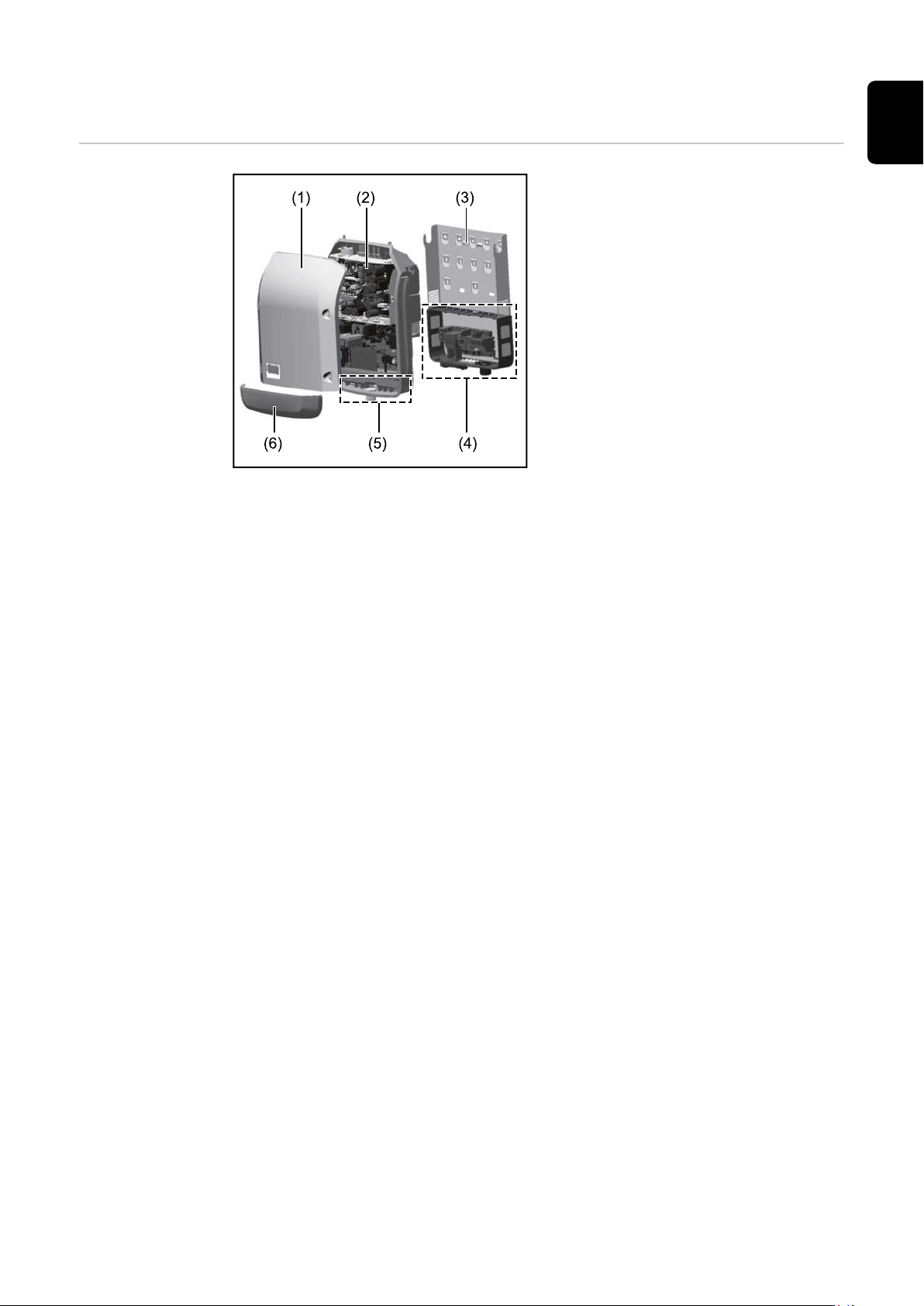
Device concept Device design:
(1) Housing cover
(2) Inverter
(3) Mounting bracket
(4) Connection area including DC
main switch
(5) Data communication area
(6) Data communication cover
The hybrid inverter converts the direct current generated by the PV modules into
alternating current. This alternating current is synchronized with the grid voltage
and fed into the public grid. Moreover, the solar energy can also be stored in a
connected battery for later use.
EN
The hybrid inverter has been developed specifically for use in grid-connected
photovoltaic systems. A backup power mode is possible if the cabling is set up
accordingly.
Thanks to its design and operating principle, the inverter is extremely safe both
to install and to operate.
The inverter monitors the public grid automatically. In the event of abnormal grid
conditions, the inverter ceases operating immediately and stops feeding power
into the grid (e.g. if the grid is switched off, if there is an interruption, etc.).
The grid is monitored by monitoring the voltage, frequency and islanding conditions. The inverter switches to backup power mode if it has been cabled up accordingly.
Operation of the inverter is fully automatic.
The inverter is designed to draw as much power from the PV modules as possible.
Depending on the operating point, this power is either stored in the battery, fed
into the grid or used for the household network in backup power mode.
As soon as the energy provided by the PV modules is no longer sufficient, the
power from the battery is fed into the home. Depending on the setting, power
may also be obtained from the public grid in order to charge the battery.
If the inverter becomes too hot, it automatically reduces the current output
power or charging power, or switches to backup power mode in order to protect
itself.
Reasons for the inverter becoming too hot include the ambient temperature being too high or inadequate heat dissipation (e.g. if it is installed in a switch cabinet
without suitable heat dissipation).
IMPORTANT! The battery must only be switched on when the inverter is in
Standby mode.
13

Proper use The solar inverter is exclusively intended for charging a battery with direct cur-
rent from solar modules, or for converting this direct current into alternating
current and feeding it into the public grid or the household network in emergency power mode.
The following actions constitute improper use:
Any use above and beyond this purpose
-
Making any modifications to the inverter that have not been expressly ap-
-
proved by Fronius
Installing components that are not distributed or expressly approved by
-
Fronius
Operating the device with a battery that has not been approved by Fronius
-
Operating the equipment with an energy meter that has not been approved
-
by Fronius
Fronius shall not be liable for any damage resulting from such action.
No warranty claims will be entertained.
Proper use also includes:
Carefully studying and obeying the Installation and Operating Instructions
-
Performing all stipulated inspection and maintenance work
-
When designing the photovoltaic system, ensure that all of its components are
operated within their permitted operating ranges at all times.
Observe all the measures recommended by the solar module manufacturer to
ensure that the solar module retains its properties in the long term.
Warning notices
on the device
Observe the stipulations of the power supply company concerning energy fed into the grid, emergency power mode and the operation of storage systems.
The Fronius Symo Hybrid is a grid-connected inverter with an emergency power
function – it is not a stand-alone inverter. The following restrictions must therefore be observed in emergency power mode:
Emergency power mode may be in operation for at least 1500 hours
-
Emergency power mode may be in operation for more than 1500 operating
-
hours if 15% of the duration of the inverter's grid power feed operation is not
exceeded at the relevant time
There are warning notices and safety symbols on and in the inverter. These warning notices and safety symbols must not be removed or painted over. They warn
against incorrect operation, as this may result in serious injury and damage.
14

6
6
6
6
6
Safety symbols:
Danger of serious injury and dam-
age due to incorrect operation
Do not use the functions described
here until you have fully read and
understood the following documents:
These Operating Instructions
-
All the Operating Instructions
-
for the system components of
the photovoltaic system, especially the safety rules
Dangerous electrical voltage
Wait for the capacitors to dis-
charge.
Text of the warning notices:
WARNING!
Danger from electric current.
This can result in serious injury or death.
Before opening the device, it must be disconnected at the input and output.
▶
Wait for the capacitors to discharge (6 minutes).
▶
EN
Product registration
Symbols on the rating plate:
CE mark – confirms compliance with applicable EU directives and
regulations.
WEEE mark – waste electrical and electronic equipment must be
collected separately and recycled in an environmentally sound manner
in accordance with the European Directive and national law.
RCM mark – tested in accordance with the requirements of Australia
and New Zealand.
Why do I need to register?
By registering easily and for free, you will benefit from additional years of warranty. You only need to fill out a few details and confirm the registration.
Who can register a device?
The warranty agreement is concluded between Fronius and the warranty holder
(owner of the installed system). For this reason, the system must be registered by
the warranty holder using their Solar.web login credentials. Registration may only
be performed by third parties if they have been authorised to do so. Non-compliance may result in a penalty. The warranty will be invalid if incorrect details are
provided.
How can I register?
Log in to the website www.solarweb.com and click on the "Product registration"
field. More information can be found in the product registration area.
15

Where can I find the serial number for my product?
The serial number can be found on the rating plate of the Fronius device.
For the Solar Battery, only use the serial number shown in the picture. The serial
numbers of the individual battery modules are not relevant.
16

Fronius Solar Battery
(1)
(2)
(3)
(4)
(5)
(6)
EN
Device concept
Device design:
(1) Battery management module
(2) Side panel
(3) Lid
(4) Fuses
(5) Data converter
(6) Battery module (1.2 kWh usable
capacity)
With the market launch of its new Fronius Energy Package, Fronius is introducing
an inverter that can be used to store energy. One of the key components is the
Fronius Solar Battery, which contains a lithium-ion rechargeable cell. The Fronius
Solar Battery supplements the Fronius hybrid inverter by adding storage functionality. This means that the solar energy from the solar modules can be stored
for later use.
The storage system is only suitable for operation in conjunction with Fronius hybrid inverters.
Thanks to its design and operating principle, the storage system is extremely safe
both to install and to operate. A high-performance lithium-ion phosphate battery
is used (LiFePO4), which is based on the latest technology and complies with the
highest safety standards.
When used in conjunction with the Fronius inverter, operation of the storage system is fully automatic.
If proper charging of the batteries in the Fronius Energy Package cannot be
guaranteed for an extended period of time (over several weeks or months) for any
reason, we strongly recommend that the following steps are undertaken to prevent the deep discharge of the battery modules:
switch off the main switch of the Fronius Solar Battery
-
remove the DC fuses from the fuse holder
-
remove the orange power connector from the individual battery modules
-
Proper use The Fronius Solar Battery is exclusively intended for taking direct current from a
Fronius hybrid inverter and storing it for later use.
The following actions constitute improper use:
Any use above and beyond this purpose
-
Making any modifications to the storage system that have not been expressly
-
approved by Fronius
Installing components that are not distributed or expressly approved by
-
Fronius
Operating the system with an inverter that has not been approved by Fronius
-
Operating the equipment with an energy meter that has not been approved
-
by Fronius
17

Fronius shall not be liable for any damage resulting from such action.
No warranty claims will be entertained.
Proper use also includes:
Carefully studying and obeying the installation and operating instructions
-
performing all stipulated inspection and maintenance work
-
Observe the stipulations of the power supply company concerning energy fed into the grid and the operation of storage systems.
Increase in storage capacity
State of charge
(SOC) accuracy
The storage capacity of the Fronius Solar Battery can also be increased after
purchase to a maximum capacity of 9.6 kWh of usable energy.
The capacity is increased by adding additional battery modules and this must be
carried out by a qualified electrician.
Capacity can be expanded within 2 years from the date of purchase, but a maximum of 30 months following dispatch from Fronius Austria.
The capacity cannot be increased after this for technical reasons. Observe the
stipulations of the distribution network operator concerning energy fed into the
grid and the operation of storage systems.
Adding or replacing a memory module can lead to inaccuracies when calculating
the state of charge (SOC). Straight lines and jumps can occur, in particular immediately after the upgrade. These only affect the display of the state of charge
and do not affect operation of the device.
SOC jump
Warning notices
on the device
SOC straight line
Warning notices and safety symbols are affixed to the battery. These warning notices and safety symbols must not be removed or painted over. They warn against
incorrect operation, as this may result in serious injury and damage.
18

Safety symbols – Text of the warning notices:
CAUTION!
Incorrect handling or failing to observe these notices and the operating
instructions is extremely dangerous. It may give rise to thermal/electrical or fire hazards, thereby resulting in serious injuries.
Please read the Operating Instructions carefully while also ensuring
compliance with the safety instructions during use!
To avoid electric shocks:
Do not dismantle or modify the device
-
Do not allow any water to enter the device
-
Do not allow any foreign substances or material to enter the device
-
Do not touch any connections directly
-
EN
To avoid overheating, fire, electric shocks or injuries:
Do not use any unspecified charging devices
-
Do not use in room temperatures of 35 °C or above
-
Do not use in unstable environments
-
Do not expose to any strong vibrations
-
To avoid the risk of fire:
Do not short-circuit individual connections
-
Avoid overheating
-
What to do in an emergency:
Fire:
a)
Suitable extinguishing agents: CO2 or powder extinguisher; fire extin-
-
guishing equipment that involves the use of water can result in electric
shocks.
Notify fire brigade
-
Notify anyone who is in danger
-
Switch off main switch
-
Open residual current-operated circuit breaker
-
Flooding:
b)
Switch off main switch
-
Open residual current-operated circuit breaker
-
Protect system from water, pump water away
-
Undefined operating status (see also section titled "Undefined operating
c)
statuses" on page 134):
Ensure adequate ventilation
-
Switch off main switch
-
Open residual current-operated circuit breaker
-
19

The various operating modes
Operating modes
– Explanation of
symbols
Solar module
Generates direct current
Inverter – Fronius hybrid
Converts the direct current into alternating current and charges
the battery. Thanks to the built-in system monitoring function, the
inverter can be integrated into a network using WLAN technology.
Battery
Connected to the inverter on the DC side and used to store electrical energy.
Photovoltaic system consumers
The consumers connected to the PV system (single or threephase)
Meter – Fronius Smart Meter
For optimum energy management. You can have the meter installed in a switch cabinet by your electrical installer. Energy profiling is possible through the use of several Smart Meters. Additional consumers or generators in the system can be measured
and monitored.
Operating mode:
Inverter
Emergency power function
The inverter is delivered ready for supplying emergency power.
However, the electrical installer must set up the emergency power
function in the switch cabinet. In emergency power mode, the PV
system operates as a stand-alone island.
Fronius Ohmpilot
To use surplus energy to heat water.
Additional inverter in the system (e.g. Fronius Symo)
Converts the direct current into alternating current. Cannot,
however, be used to charge batteries and is not available to
provide emergency power.
Grid
The Fronius hybrid inverter can be used purely as an inverter without a battery
connected to it.
20
EN
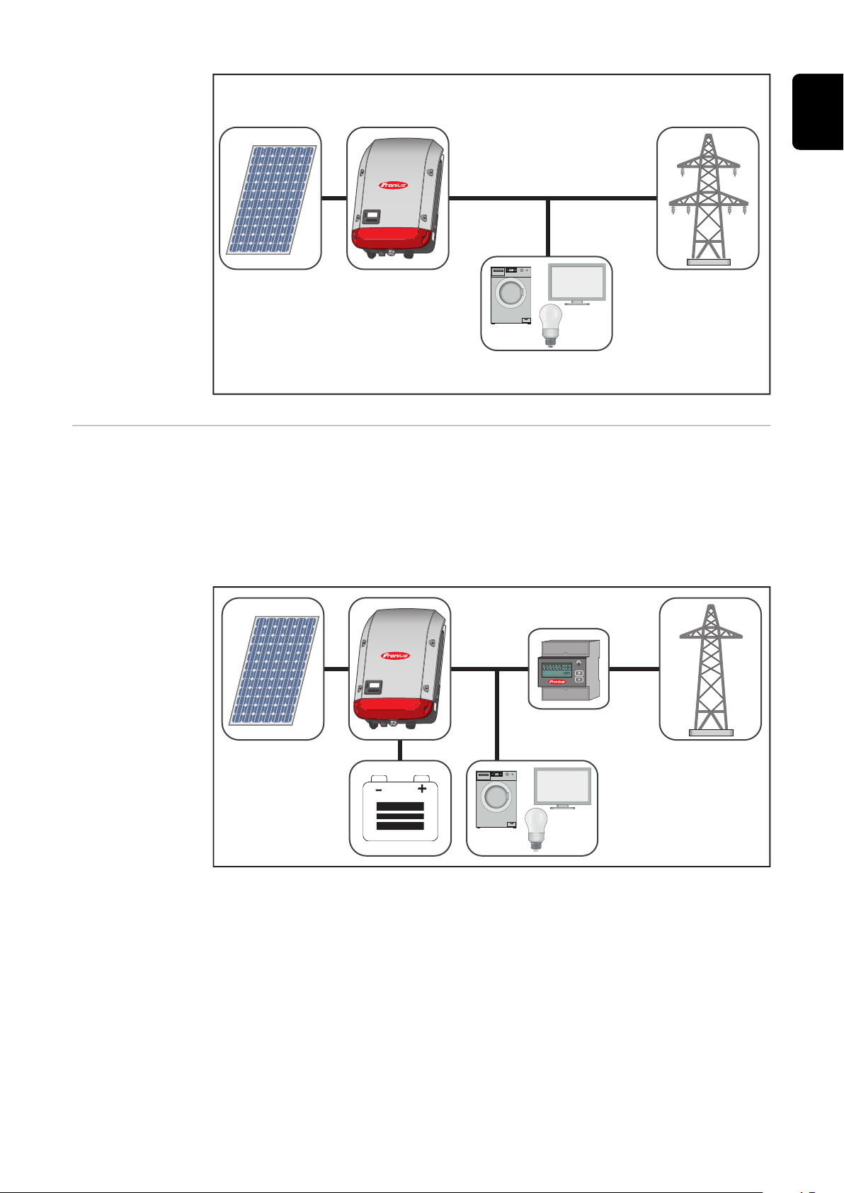
Operating mode
- Inverter plus
battery
To ensure fault-free regulation, parallel operation of several batteries is not permitted.
To optimise self-consumption in your PV system, you can use a battery as a storage system. The battery is connected to the inverter on the DC side. As a result,
there is no need for multiple current conversion processes, which results in
greater efficiency.
21

Operating mode
- Inverter plus
battery and multiple Smart
Meters
Operating mode
- inverter with
battery, ACcoupled to another inverter
Operating mode
- Inverter plus
battery and
emergency
power function
22
IMPORTANT! In emergency power mode, an increased nominal frequency is
used in order to avoid parallel operation with other generators.
To ensure fault-free regulation, parallel operation of several batteries is not permitted.
When the hybrid PV system is equipped with all the available features, the inverter can:
Feed energy into the grid
-
Supply the devices that are connected to the PV system with power in the
-
event of a power failure
Use any excess energy to charge the battery.
-

EN
Operating mode
- Inverter plus
battery, Ohmpilot and emergency power
function
IMPORTANT! In a hybrid PV system with Fronius Ohmpilot and all the system
features, the Ohmpilot cannot be operated in the event of a power failure for
control-related reasons. Therefore, it makes sense to install the Ohmpilot outside
of the emergency power circuit.
23

Operating mode
- Inverter plus
battery, additional inverter
and emergency
power function
Operating states
(only for systems
with a battery)
Battery system distinguishes different operating states. The current operating
state is displayed on the system monitoring website or in Solar.web.
Operating state Description
The battery is not active. It has either been deac-
Deactivated
tivated, or no communication with the battery or
meter is possible due to a fault.
Normal operation The system is in normal operation
Service mode has been activated. The battery is
Service mode
1)
automatically charged or discharged to a defined
SOC value and then kept at this value until service
mode is ended manually.
The Fronius Symo Hybrid recharges the battery to
Forced re-charging
counteract self discharge and maintain the set
minimum SOC (protection against deep discharge).
The battery has reached the set minimum SOC.
Min. SOC reached
The battery cannot be discharged further until
charging takes place again.
The system has been put into energy saving mode.
Energy saving mode
None of the LEDs or the battery display light up1).
Energy saving mode is automatically ended as
soon as sufficient excess energy is available again.
24
Calibration mode
1)
Deep discharge protec-
1)
tion
The system is in calibration mode. When there is
insufficient PV energy available to reach 100%,
the battery is cyclically charged to 100% for internal calibration. Under certain conditions (depending on weather, microcycles, temperature,
etc.), this can take an extended period of time.
The Fronius Symo Hybrid recharges the battery to
counteract self discharge and maintain the minimum state of charge.

Operating state Description
Start
1) Only available for the Fronius Solar Battery.
The storage system starts from energy saving
mode (standby).
EN
25

Emergency power mode
Prerequisites for
emergency
power mode
In order to use the hybrid inverter's emergency power function, the following
prerequisites must be fulfilled:
Correct cabling of the emergency power system in the electrical installation
-
(see document "Fronius Energy Package - Examples of emergency power
switchover").
The Fronius Smart Meter must be installed at the feed-in point and con-
-
figured.
Latest firmware on the inverter - if required, perform a firmware update.
-
The emergency power sticker provided with the inverter must be attached to
-
the electrical distributor.
Select Alternative (emergency power) setup in the CONFIG menu on the in-
-
verter (see Installation Instructions).
Change the required settings in the emergency power area in the IO mapping
-
menu (Fronius system monitoring web page → Settings → IO mapping →
Emergency power).
Set the emergency power to "Auto" in the system overview (Fronius system
-
monitoring web page → Settings → System overview → Emergency power operating mode).
If there are additional inverters in the system, these should be installed outside
of the emergency power circuit, but within that for the Fronius Smart Meter, see
Operating mode - Inverter plus battery, additional inverter and emergency
power function on page 24.
NOTE! Emergency power mode is not possible with the batteries from the LG
Chem ResuH series.
Transitioning
from feeding energy into the grid
to backup power
mode
Transitioning
from backup
power mode to
feeding energy
into the grid
The public grid is monitored by the inverter's internal grid and system pro-
1.
tection unit and by the Fronius Smart Meter connected to it.
The public grid fails or specific grid parameters are dropped below or ex-
2.
ceeded.
The inverter carries out the measures necessary according to the country
3.
standard and then switches off.
The inverter starts backup power mode after a checking period.
4.
All loads in the household that are in the backup power circuit are supplied
5.
by the battery and the PV modules. The remaining loads are not supplied
with power and are safely isolated.
The inverter is operating in backup power mode.
1.
The public grid is functioning correctly again.
2.
The Fronius Smart Meter monitors the grid parameters on the public grid
3.
and passes this information to the inverter.
The stability of the returned public grid is determined by checking the meas-
4.
ured values of the Fronius Smart Meter.
The inverter ends backup power mode.
5.
All circuits are reconnected to the public grid and are supplied by the grid.
6.
The inverter can start feeding energy into the grid again after performing the
7.
grid checks required by the relevant standard.
26

Restrictions in
backup power
mode
In backup power mode, some electrical appliances cannot function properly as
the starting currents are too high (e.g. fridges and freezers). It is recommended
to switch off non-essential loads during backup power mode.
Switching from grid-connected operation to backup power mode takes a little
while. For this reason, the battery system with backup power function cannot be
used as an uninterruptible power supply, for example for computers.
If no energy is available from the battery or the PV modules during backup
power mode, this mode is automatically ended, irrespective of whether power is
available from the public grid or not.
Fronius Solar Battery: If sufficient energy becomes available from the PV modules once again, backup power mode starts again automatically.
BYD Battery-Box Premium: The system must be restarted manually as soon as
sufficient energy from the PV modules or the public grid is available again. For
the correct power-up sequence, see chapter BYD Battery-Box Premium on page
34.
If consumption is too high, backup power mode is interrupted and status code
"143 - Backup power overload" appears. The maximum power in backup power
mode according to the technical data must be observed!
EN
Backup power
and energy saving mode
Fronius Ohmpilot and backup
power mode
If the inverter is operating in backup power mode, energy saving mode is automatically active. Under the following conditions, the battery and the inverter are
switched to energy saving mode after a waiting time of 8 - 12 minutes:
The battery is discharged to the minimum state of charge and no energy is
-
coming from the PV modules.
The inverter is in an error state that is not acknowledged automatically (e.g.
-
multiple overload).
The inverter is set to energy saving mode (standby mode) using the display
-
setting.
If the battery and inverter are in energy saving mode, the system is reactivated
by the following actions (applies only for Fronius Solar Battery):
Enough energy is available from the PV modules.
-
The public grid is functioning again.
-
The battery's POWER switch is switched off and on.
-
More information on energy saving mode can be found in chapter Energy saving
mode on page 29
The Fronius Ohmpilot is not suitable for backup power mode. If a Fronius Ohmpilot is used, it should be installed outside of the backup power circuit (see Oper-
ating mode - Inverter plus battery, Ohmpilot and emergency power function on
page 23).
NOTE!
Risk from an active Ohmpilot in backup power mode.
This may result in loss of the backup power supply.
Never turn on boost mode on the Ohmpilot.
▶
Switch off the automatic circuit breaker on the Fronius Ohmpilot (if fitted).
▶
Before a power outage occurs, any function that would exceed the power
▶
limits in backup power mode must be disabled.
27

Disable functions that would exceed the power limits in backup power mode:
Set measuring of heating rod to manual on the Ohmpilot (under "General -
1
General Settings - Heating 1 - Manual").
Disable the "Legionella prevention (h)" and "Adapt day curve" settings (under
2
"General - General Settings - Heating 1").
28
Energy saving mode
General Energy saving mode (standby) is used to reduce the self-consumption of the sys-
tem. It is available from version 1.4.1-11 of the system monitoring software. Both
the inverter and the battery automatically switch into energy saving mode under
certain conditions.
Fronius Symo Hybrid
If the battery is flat and no PV energy is available, the inverter switches to energy
saving mode. Only the inverter's communication with the Fronius Smart Meter
and Fronius Solar.web is maintained.
Fronius Solar Battery
When the battery is in energy saving mode, the display remains dark. In Solar.web, energy saving mode is indicated by an "i" next to the battery symbol. In
the energy balance view, the SOC (State of Charge) of the Fronius Solar Battery
is not displayed for the duration of energy saving mode.
BYD Battery-Box Premium
In Solar.web, energy saving mode is indicated by an "i" next to the battery symbol.
EN
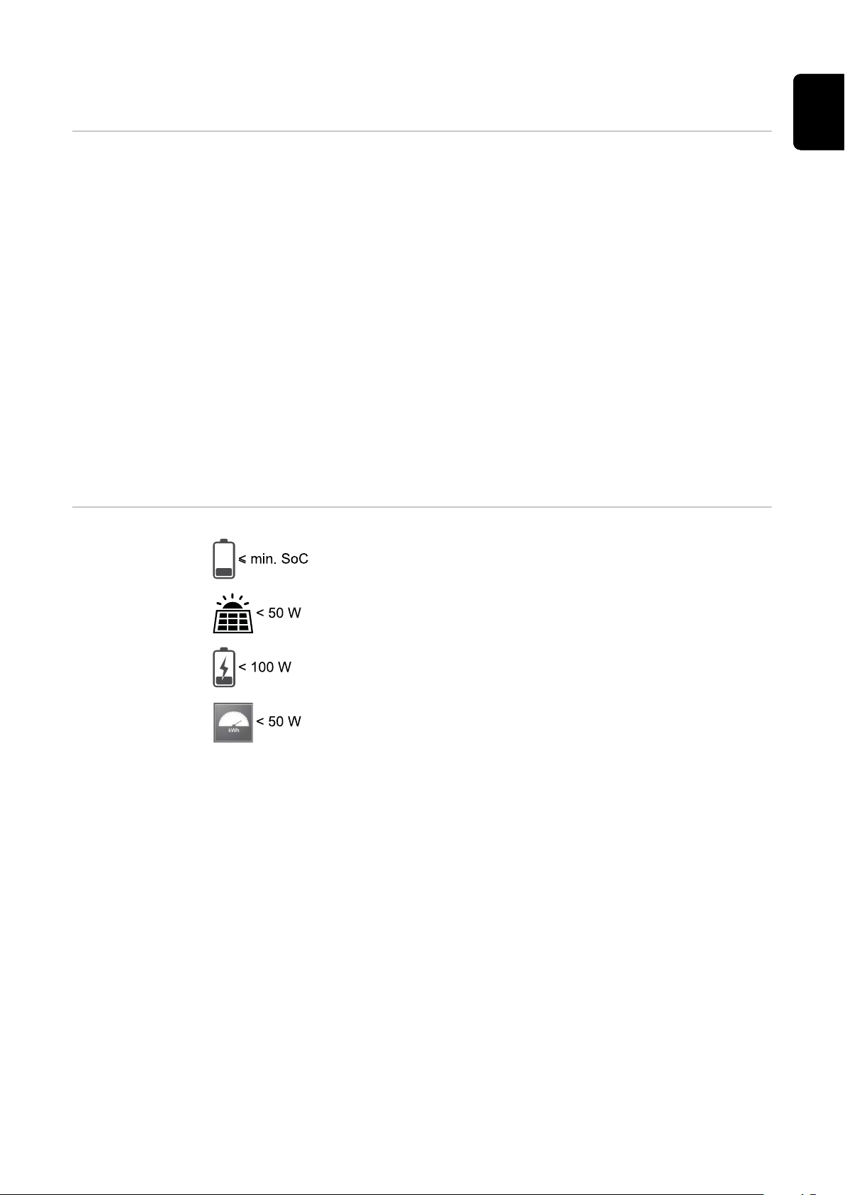
Fronius Solar
Battery and
Fronius Symo
Hybrid switchoff conditions
The battery state of charge is less than or equal to the input
minimum state of charge.
The power from the PV modules is less than 50 W.
The current charging or discharging power of the battery is
less than 100 W.
Less than 50 W is available for charging the battery. The
power of feeding in for the public grid is at least 50 W less
than the power currently required in the home network.
If all the switch-off conditions are met, the battery switches into energy saving
mode within six minutes. This time delay ensures that the inverter can be restarted at least once.
The inverter automatically switches into energy saving mode after the battery.
Backup power:
If the backup power function has been activated, the battery in grid operation
does not switch to energy saving mode. Otherwise, the dark start (start without
grid and PV supply) of the hybrid system cannot be ensured.
During backup power mode and when the state of charge falls below the minimum limit, the battery switches to energy saving mode.
29

Fronius Symo
Hybrid and
Fronius Solar
Battery switchon conditions
Special case If the inverter does not operate for 8–12 minutes (e.g.: error), or if there is an in-
If one of the following conditions is met for at least 30 seconds, energy saving
mode is ended:
Energy saving mode is no longer permissible owing to a changed setting on
-
the user interface of the inverter.
More than 50 W is available for charging the battery. The power of feeding in
-
for the public grid is at least 50 W greater than the power currently required
in the home network.
If a dynamic power reduction of 0 is set, or if the system is operating in
-
backup power mode, the power of feeding in for the public grid is always less
than the required power in the home network.
There is a separate condition for this case (dynamic power reduction < 300 W
or active backup power mode): If the PV power is above a specified threshold
(50 W), the energy saving mode is ended.
Battery charging from the public grid is requested via the website.
-
The battery is recharged to restore the minimum state of charge or to per-
-
form a calibration.
The Fronius Solar Battery is woken up as soon as the Symo Hybrid is generat-
-
ing PV power. This guarantees reliable operation of the battery.
terruption in the electrical connection between the inverter and battery, the battery switches into energy saving mode in any case. This reduces self discharge of
the battery.
Indicators on the
devices and user
interfaces
During energy saving mode:
Orange status LED lights up steady
-
The inverter website can be accessed
-
All available data is saved and sent to Solar.web
-
The current available data can be viewed on Solar.web
-
Energy saving mode is shown on the website of the inverter and in Solar.web by
an "i" beside the battery symbol in the system overview.
30

Calibration charging for the Fronius Solar Battery
EN
Benefits of calibration charging
General Determining the exact state of charge (SOC) of the battery is important for oper-
Natural differences in the individual cell capacities and the small amount of self
discharge that occurs in all batteries cause the cell voltages to diverge. This
makes the SOC value less accurate, which affects the operation. If no steps are
taken, the battery will become damaged.
Periodic calibration charging brings all cells of the battery to the same state of
charge, and calibrates the SOC value. This ensures a longer service life of the
battery cells.
ation management. To ensure this happens, the battery must regularly be
charged to 100%. This allows the SOC value to be calibrated.
Fronius Solar Battery:
Calibration charging occurs automatically during operation after several charge
and discharge cycles. When calibration charging is carried out depends on two
crucial factors:
Average state of charge
-
Energy throughput of the battery
-
As these factors are extremely weather dependent, the time of a calibration
charge can vary depending on the time of year.
Conditions for
starting the calibration charge
(Fronius Solar
Battery)
Calibration charging procedure
(Fronius Solar
Battery)
The following description of calibration charging is valid from version 1.4.1-12 of
the Fronius system monitoring software.
One charge and discharge cycle of the Fronius Solar Battery corresponds to an
energy throughput of 48 Ah per battery module. Calibration charging occurs cyclically according to the following conditions:
After 3 full charge and discharge cycles and a SOC of 80%
-
After 5 full charge and discharge cycles and a SOC of 50%
-
After 7 full charge and discharge cycles, independent of the SOC
-
For newly installed systems and for module replacement or expansion, a calibration charge is started automatically after 30 minutes.
Calibration charging primarily occurs with the entire PV power. If insufficient PV
energy is available, energy is drawn from the public grid. This is also the case
even if the "Battery charging from DNO grid" function is deactivated, as this is a
critical requirement.
The SOC is calculated per battery module. For this reason, each battery module
must reach a SOC of 100%.
31

Calibration process (Fronius
Solar Battery)
The start conditions must be fulfilled
1.
The battery is charged to 100% with a minimum current of 6.5 A or the total
2.
PV power.
So that a SOC of 100% can be reached for each battery module, one of the
3.
following two conditions must be fulfilled for at least 2 minutes (for each cell
in every battery module):
Minimum cell voltage ³ 3.45 V and current < 100 mA
-
Minimum cell voltage > 3.5 V independent of current
-
When a battery module reaches one of these conditions, the current is lim-
4.
ited to prevent an overload. A current in the two-digit mA range flows over a
bypass resistor
Unneeded PV power is reused directly
5.
Once all cells in all battery modules have fulfilled one of the two conditions,
6.
the SOC is set to 100% and calibration charging is complete.
Duration of calibration charging
(Fronius Solar
Battery)
Limitations during calibration
(Fronius Solar
Battery)
Due to tolerances in the cells, they are not always charged and discharged at the
same rate. As cells and battery modules are connected in series and the slowest
cell determines the charging and discharging duration, some calibration charges
need more or less time.
In rare cases, calibration charges or full charge cycles (depending on the time of
year, e.g. in the winter months) can lead to large variations in the cell voltages in
the battery modules. In calibration mode, one cell charges more quickly than the
others. This cell then begins redistribution. The other cells can then only be
charged with a reduced charging current. It takes longer for these cells to reach
the target value.
If the battery is regularly charged completely, calibration charges are rarely required. The cells are calibrated during every charge with 100% SOC.
In the winter months. where there are few full charges and a lower energy
throughput, calibration charges can take longer, as higher variations between the
battery modules must be redistributed.
Drawing energy from the battery (discharging) is not possible
-
Self-consumption optimisation is disabled while calibration charging is in
-
progress
Charging from the grid can still occur if the "Battery charging from DNO
-
grid" function is not activated, as this process concerns system-relevant service charging
Zero feed-in continues according to the standard and service charging can
-
even be started if you wish to expand or replace battery modules during calibration
Emergency power mode can be started – calibration charging is interrupted
-
Display during
calibration
charge (Fronius
Solar Battery)
32
As soon as calibration charging starts, it becomes visible in Fronius Solar.web
(current and energy balance view) or on the web interface of the Fronius Symo
Hybrid inverter.

In Fronius Solar.web or on the web interface of the inverter,
the calibration charge information is displayed in the overview. Clicking on the battery symbol (see the image on the
left) displays the information "The battery is in calibration
mode"
In the energy balance display in Solar.web, both the start and end of the calibration charge is displayed by changing the battery status ("Battery Mode: Normal
→ Calibrate" and "Battery Mode: Calibrate → Normal")
The following graphic shows calibration charging of the Fronius Solar Battery in
the energy balance view. At the start of calibration charging, the total PV production is used to charge the battery. From the point where one cell is fully
charged, only a certain charging current is drawn by the battery. This charging
current decreases towards 0 A as the cell voltage increases.
EN
As during normal operation, the status "charging" (CHG) is shown on the battery
display and the relevant charging current in ampere is displayed. If the charging
current drops to below 0.3 A, 0 A is shown on the display, even though calibration
charging continues.
In Fronius Solar.web, the SOC value for the entire battery is displayed. On the
battery display, the SOC values of the individual battery modules can be viewed.
33

Suitable third-party batteries for Fronius Symo
Hybrid
LG Chem ResuH Fronius expressly points out that third-party batteries are not Fronius products
and that Fronius is not a trader or distributor of these batteries. This means that
Fronius accepts no liability for these batteries and cannot offer any kind of warranty.
The Fronius Symo Hybrid can be operated with an LG Chem type RESU7H(TypeR) or RESU10H(Type-R) high-voltage battery.
A Fronius Checkbox 500V is required to connect an LG battery to a hybrid inverter. Backup power mode is not possible when operating the LG Chem high-voltage
battery.
Read this document and the Installation Instructions for the Fronius Symo Hybrid, the Fronius Checkbox 500V and the third-party battery before installation
and commissioning.
All Fronius documents are available at the following address:
www.fronius.com/photovoltaics/infocentre/tech-support/how-to-install
BYD BatteryBox Premium
The documentation for the LG Chem ResuH is enclosed with the third-party battery, or you can acquire it from the third-party manufacturer.
WARNING!
Danger due to DC voltage from the inverter and battery.
This can result in serious injury or death.
The Fronius Checkbox 500V must be installed in the system in accordance
▶
with the Installation Instructions.
Read and follow the "Fronius Checkbox 500V" Installation Instructions. The
▶
Installation Instructions are supplied with the Fronius Checkbox 500V.
Wire the "Third-party battery with Fronius Symo Hybrid and Fronius Check-
▶
box 500V" in accordance with the Circuit Diagram. The Circuit Diagram is
supplied with the Fronius Checkbox 500V.
Fronius expressly points out that third-party batteries are not Fronius products
and that Fronius is not a trader or distributor of these batteries. This means that
Fronius accepts no liability for these batteries and cannot offer any kind of warranty.
The Fronius Symo Hybrid can be operated with the following BYD Battery-Box
Premium variants:
HVM 8.3*
-
HVM 11.0
-
HVM 13.8
-
HVM 16.6
-
HVM 19.3
-
HVM 22.1
-
34
Parallel operation of up to three BYD HVM batteries is possible in compliance
with BYD specifications. A combination of three HVM 22.1 is not permitted.
* Note for systems with backup power switchover with Fronius Symo Hybrid and
ON
OFF
1
BYD Battery-Box Premium HVM 8.3:
If there is a power failure, there is no energy available from the PV system and
the battery has a low state of charge (SOC typically < 20%), the system may no
longer be able to switch to backup power mode.
Read this document and the Installation Instructions for the Fronius Symo Hybrid and the third-party battery before installation and commissioning.
All Fronius documents are available at the following address:
www.fronius.com/photovoltaics/infocentre/tech-support/how-to-install
Obsolete software states may lead to incompatibilities between the inverter and
the battery. If a corresponding message is displayed:
Update inverter software - see Services – Firmware update on page 89
-
Update battery software - see the battery documentation
-
The documentation for the BYD Battery-Box Premium is enclosed with the thirdparty battery, or you can acquire it from the third-party manufacturer.
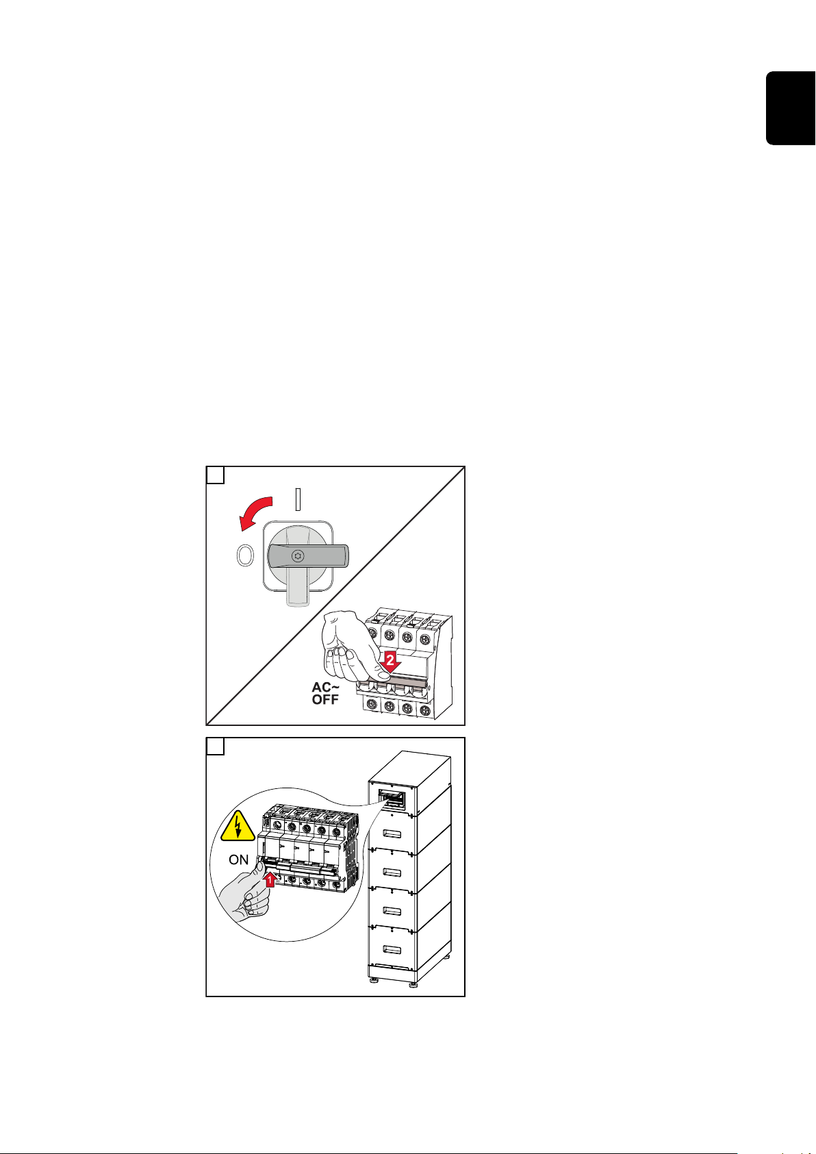
IMPORTANT!
To ensure reliable operation with a BYD Battery-Box Premium HVM, the following
switch-on sequence for the system must always be observed.
EN
1
Set the DC disconnector to the "Off"
switch position. Turn off the automatic
circuit breaker.
2
Switch on the battery.
35

ON
OFF
2
3
Switch on the automatic circuit breaker. Set the DC disconnector to the
"On" switch position.
36

Operation
37

38

Data communication
(2)
PIN 1
PIN 2
PIN 1
PIN 2
PIN 3
(3)
(1)
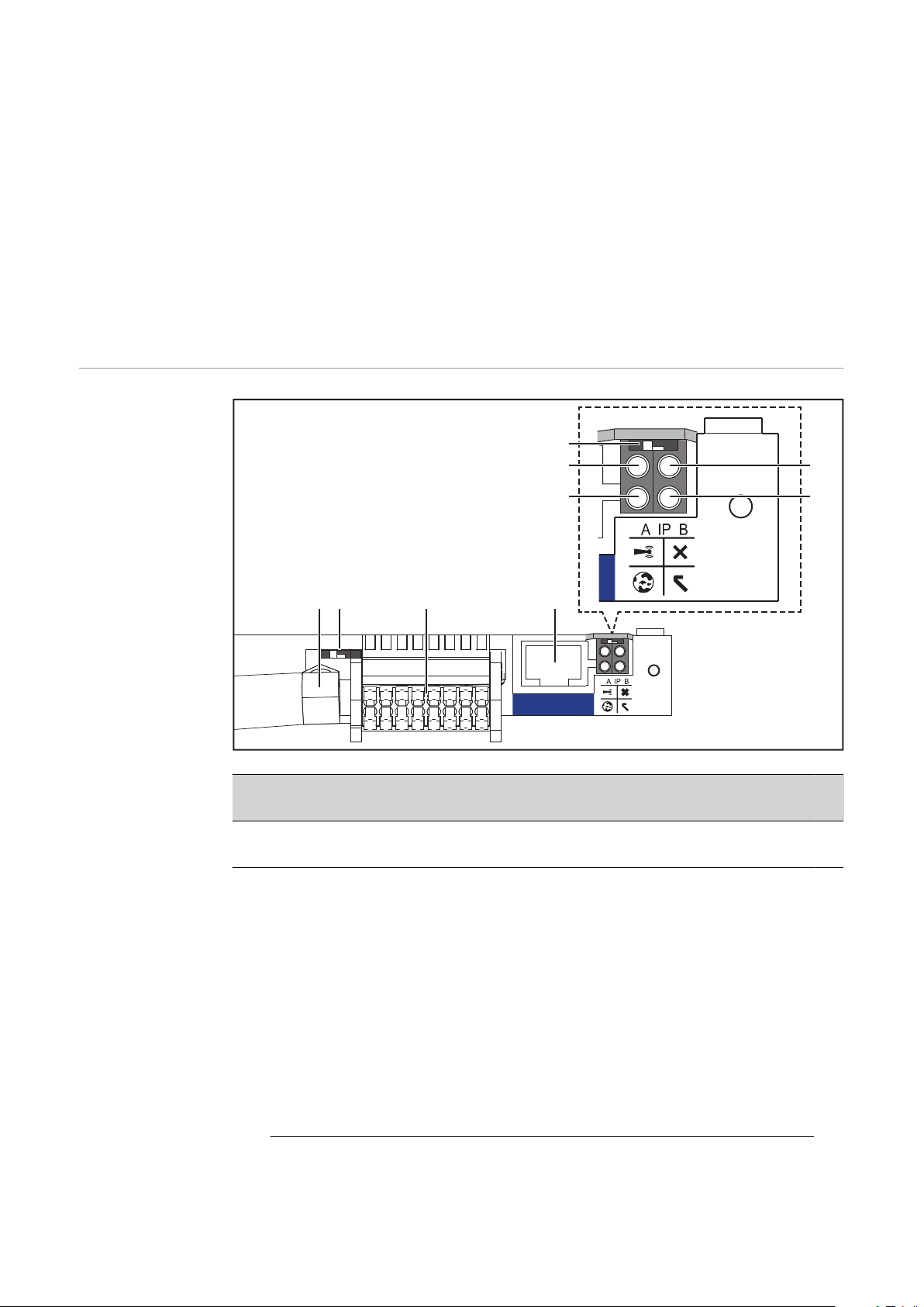
Data communication area
Ite
m Designation
EN
(1) Switchable multifunction current interface
Use the 2-pin mating connector supplied with the inverter to connect to
the multifunction current interface.
(2) Floating switch contact with mating connector
Max. 250 V AC / 4 A AC
Max. 30 V DC / 1 A DC
Max. 1.5 mm² (AWG 16) cable cross-section
Pin 1 = NO contact (normally open)
Pin 2 = C (common)
Pin 3 = NC contact (normally closed)
Use the mating connector supplied with the inverter to connect to the
floating switch contact.
(3) System monitoring with WLAN antenna
General The inverter is fitted with the WLAN-enabled system monitoring and energy
management unit (Fronius Datamanager) as standard.
Various functions are included with the Fronius system monitoring, such as:
39
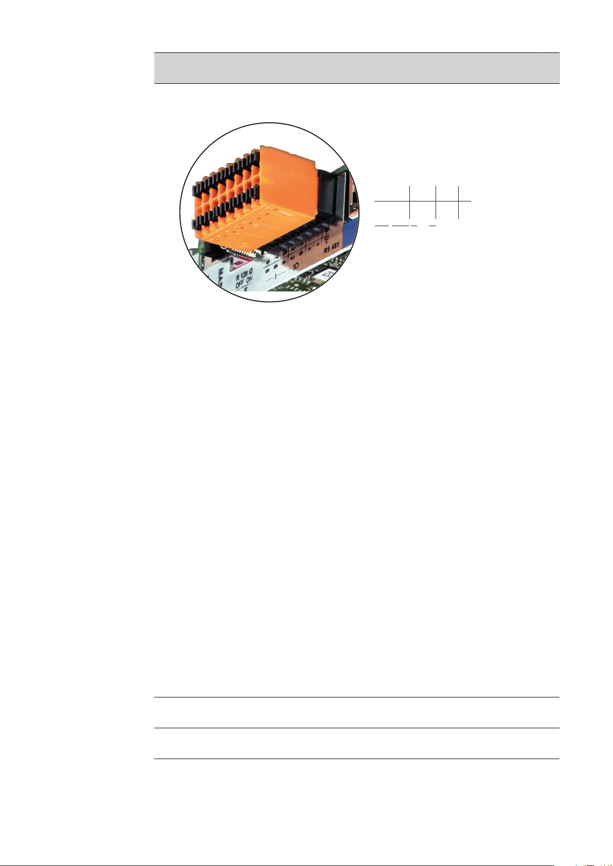
Controls, con-
(5)
(1)
(6)(7)(8)(9)
(4)
(2)
(3)
LAN
nections and indicators on the
system monitoring unit
Dedicated web page displaying current data and a wide range of settings
-
Option of connecting directly to Fronius Solar.web
-
Internet connection via WLAN or LAN
-
Ability to control the inverter load by specifying power limit values, minimum
-
or maximum running times or target running times
Ability to control the inverter via Modbus (TCP)
-
Ability to assign control priorities
-
Ability to control the inverter by means of connected meters (Fronius Smart
-
Meter)
Ability to control the inverter via a ripple control signal receiver (e.g. by spe-
-
cifying the reactive power or effective power)
Dynamic power reduction, taking self-consumption into account
-
Ability to control battery charging in line with the control targets set
-
Ability to control emergency power mode
-
No
. Function
(1) IP switch
For switching the IP address:
Switch position A
Default IP address with activating of the WLAN access point
Setting the IP switch to position A also opens an access point to enable a direct WLAN connection to system monitoring.
Access data for this access point:
Network name: FRONIUS_239.XXXXXX
Key: 12345678
System monitoring can be accessed by:
Using the DNS name "http://datamanager"
-
Using the IP address 169.254.0.180 for the LAN interface
-
Using the IP address 192.168.250.181 for the WLAN access point
-
40

No
. Function
Switch position B
Assigned IP address
System monitoring uses an assigned IP address (factory setting: dynamic (DHCP))
The IP address can be set on the system monitoring web page.
(2) WLAN LED
Flashing green: System monitoring is in Service mode
-
(IP switch on the system monitoring plug-in card is in position A or
Service mode has been activated via the inverter display, the WLAN
access point is open)
Lights up green: WLAN connection established
-
Flashing green/red (alternately): WLAN access point has timed out
-
following activation (1 hour)
Lights up red: no WLAN connection
-
Flashing red: faulty WLAN connection
-
(3) Solar.web connection LED
Lights up green: Fronius Solar.web connection established
-
Lights up red: Fronius Solar.web connection is required but has not
-
been established
Not lit: no Fronius Solar.web connection is required or the option for
-
sending data to Fronius Solar.web has been deactivated
EN
(4) Supply LED
Lights up green: internal communication system is providing an ad-
-
equate power supply; system monitoring is ready for use
Not lit: no power is being supplied by the internal communication sys-
-
tem
Flashing red: update in progress
-
IMPORTANT! Never interrupt the power supply while an update is in
progress.
Lights up red: update failed
-
(5) Connection LED
Lights up green: good connection within the internal communication
-
system
Lights up red: connection within the internal communication system
-
has been interrupted
(6) LAN connection
Ethernet interface, colour-coded blue, for connecting the Ethernet cable
41
No
D-
-
-
1
3
5
7
9
D+
+
+
0
2
4
6
8
I IO RS485
. Function
(7) I/Os
Digital inputs and outputs
Modbus RTU 2-wire (RS485):
D- Modbus data D+ Modbus data +
Int./ext. power supply
- GND
+ U
int
/ U
ext
Internal voltage output 12.8 V
or
input for an external supply voltage
>12.8 - 24 V DC (+ 20%)
Digital inputs: 0 - 3, 4 - 9
Voltage level: low = min. 0 V - max. 1.8 V; high = min. 3 V - max. 24 V DC (+
20%)
Input currents: dependent on input voltage; input resistance = 46 kOhm
Digital outputs: 0 - 3
Switching capacity when power is supplied by the system monitoring plugin card: 3.2 W in total for all 4 digital outputs
Switching capacity when power is supplied by an external power supply
delivering min. 12.8 - max. 24 V DC (+ 20%), connected to Uint / Uext and
GND: 1 A, 12.8 - 24 V DC (depending on external power supply) for each
digital output
42
The connection to the I/Os is established via the mating connector supplied.
(8) Antenna socket
This is where the WLAN antenna is connected

No
. Function
(9) Modbus termination switch (for Modbus RTU)
Internal bus terminator with 120 ohm resistor (yes/no)
Switch in "on" position: 120 ohm terminating resistor active
Switch in "off" position: no terminating resistor active
IMPORTANT! On an RS485 bus, the terminating resistor on the first and
last device must be active. For a detailed description, see the Installation
Instructions.
EN
43

Fronius Hybrid inverter
(1)
(2)
(3)
(4)
(5) (6) (7) (8)
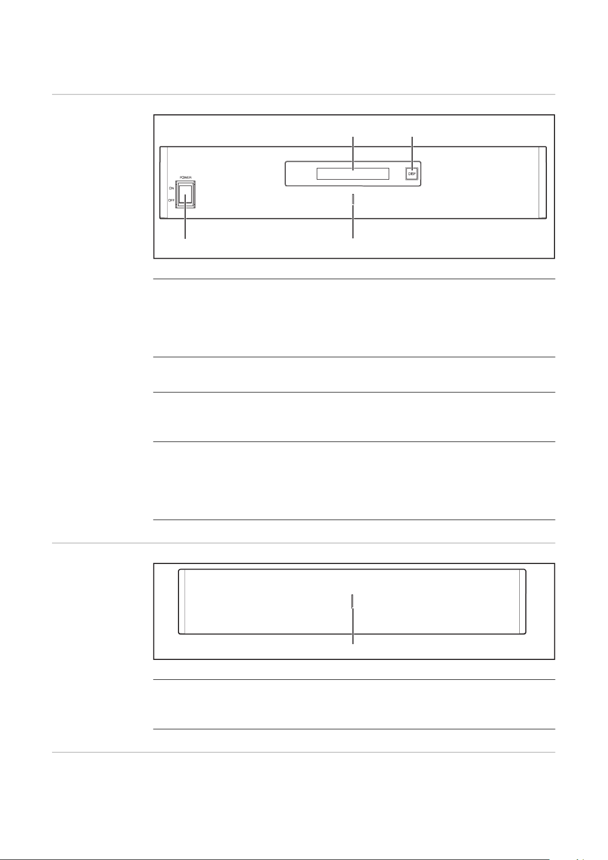
Controls and indicators
Item Description
(1) Display
For displaying values, settings and menus
Monitoring and status LEDs
(2) General status LED
Lights up steady:
If a status code is being displayed on the monitor (red for error,
-
orange for warning)
If the process of feeding energy into the grid is interrupted
-
During error handling (the inverter waits for an acknowledgement
-
or for an error to be rectified)
(3) Startup LED (orange)
Lights up steady:
If the inverter is in its automatic startup or self-test phase (as
-
soon after sunrise as the solar modules are delivering sufficient
power)
If the inverter has been switched to Standby mode in the Setup
-
menu (= feeding energy into the grid switched off manually)
If the inverter software is being updated
-
(4) Operating status LED (green)
Lights up steady:
If the PV system is working correctly after the inverter's automat-
-
ic startup phase
When system is feeding energy into the grid or is in Storage mode
-
Function keys – Allocated different functions depending on what has been selected:
44
(5) “Left/up” key
For navigating to the left and up
(6) “Down/right” key
For navigating down and to the right
(7) “Menu/Esc” key
For switching to the menu level
For quitting the Setup menu

Item Description
Standby
Relay
Clock
Display Setting
Energy Yield
(*)
(8) “Enter” key
For confirming a selection
The keys operate capacitively. Exposure to water may impair their function. If necessary, wipe the keys dry with a cloth to ensure optimum functionality.
Display The display is supplied with power via the AC grid voltage and via the PV and bat-
tery side. Depending on the setting selected in the Setup menu, the display can
be kept on all day.
IMPORTANT!
The display on the inverter is not a calibrated measuring device.
A slight inaccuracy in comparison with the utility meter used by the energy company is intrinsic to the system. A calibrated meter will be needed to calculate the
bills for the energy company.
EN
Display areas, display mode
Save symbol
Previous menu items
Currently selected menu item
Next menu items
Function key functions
(*) Scroll bar
Save symbol – Appears briefly while the set values are being saved
45
Fronius Solar Battery
(1)
(3)
(4)
(2)
(1)
Battery management module
(1) LCD display
Provides information about the status of a module (charging/discharging,
total voltage, total current strength, total remaining capacity, number of
connected modules, remaining capacity of each module, voltage/temperature etc. of the cell block)
Battery module
(2) DISP switch
Changes the information shown on the display
(3) Indicator LED
Normal status: Green
Error: Flashing red
(4) POWER ON/OFF switch
POWER ON: Switches on battery modules and battery management module (operation)
POWER OFF: Switches off battery modules and battery management
module (power supply interrupted)
(1) Indicator LED
Normal status: Green
Error: Flashing red
Display Press the DISP key to display information.
46
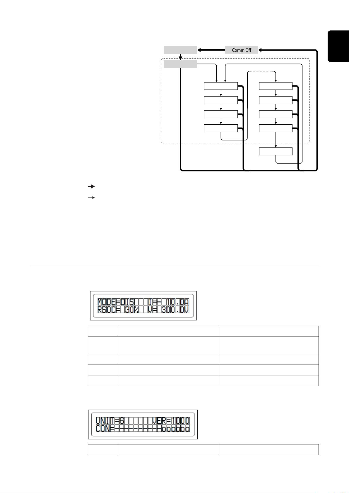
Display switching diagram
Overall
Connection
Modul Nr. 00 Modul .Nr. N
Status
Mode
Cell temp
Status
Mode
Cell temp.
Alarm bits Alarm bits
Heatsink
Display overall status
of system
Display status of individual modules
Press and hold DISP key
Press DISP key
Nr.N. Means the nth storage module
EN
Tips:
Hold down DISP key for longer than 3 seconds
-
Pressing the DISP key on the “Connection” display takes you back to the
-
“Overall” display.
“Comm Off Mode” is used for maintenance purposes.
-
Display types
"Overall" display
Display Details Display
MODE Charging/discharging and stop
RSOC Remaining system capacity 0% - 100%
I Total system current strength -999.9 A to +999.9 A
V Total system voltage 0.0 V to +999.9 V
"Connection" display
status
DIS: Discharging
CHG: Charging
Display Details Display
47

UNIT Number of connected modules 1 - 16
VER Version XXXX
CON Status of connected modules In the above example, there are
6 connected modules (no. 00 no. 05).
"Status" display
Display Details Display
M_NO Number of modules displayed 00 - 15
STAT Module status YX (Y: Current status, X: Previ-
ous status)
1X [Pre Charge]: Pre-charging
2X [Initial]: Status at beginning
3X [Normal Chg]: Normal charging
4X [Terminate]: End charging
5X [Normal Dis]: Normal discharging
6X [Over Volt]: Overvoltage
7X [Over Dis]: Deep discharge
8X
9X [Over Temp C]: Overtemperature charging
AX [Over Curr C]: Overcurrent
charging
BX [Over Temp D]: Overtemperature discharging
CX [Over Curr D]: Overcurrent
discharging
DX [Unbalance]: Cell imbalance
EX [Chg Suspend]: Charging
suspended
FX
"Mode, Current, SOC, Voltage" display
Display Details Display
M_NO Number of modules displayed 00 - 15
RSOC Remaining module capacity 0% - 100%
I System module current strength -999.9 A to +999.9 A
48
V System module voltage 0.0 V to +999.9 V

"Cell Temp., Cycle Count" display
Display Details Display
M_NO Number of modules displayed 00 - 15
CYCL Number of cycles 0000 - 9999
T Average temperature of all cells -99.9 °C to +99.9 °C
"Alarm bits" display
Display Details Display
M_NO Number of modules displayed 00 - 15
ALRM Module status 8000 [Over Volt]: Overvoltage
4000 [Terminate]: End charging
2000 [Under Volt]: Undervoltage
1000 [Over Curr]: Overcurrent
0800 [Over Temp]: Overtemperature
0400 [0]:
0200 [Resistor]: Resistor alarm
0100 [Unbalance]: Cell imbalance
Details displayed if multiple
alarms are triggered
Example: If both "Over Current"
and "Over Temp" are detected,
the following message is displayed. A higher bit level takes
priority over messages in brackets: "ALRM=1800 [Over Curr]"
EN
"Heatsink Temp" display
Display Details Display
HEATSINK_T
MP
COMM_QLInternal communication quality 0% - 100%
Temperature of the heat sink -40 °C to +119 °C
49
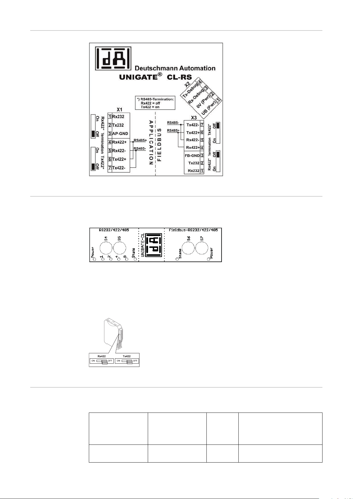
Data converter
connections
Data converter
controls and indicators
Connection to Fronius Solar Battery
Factory settings:
S4 = 0x0 (hex) = 0000 (binary)
S5 = 0x0 (hex) = 0000 (binary)
S6 = 0x1 (hex) = 0001 (binary)
S7 = 0x4 (hex) = 0100 (binary)
Connection to Fronius hybrid inverter
RS485 terminal
Rx422 = off
Tx422 = off
Data converter
LED displays
50
The data converter features 8 LEDs, the meaning of which is explained below:
Fronius Solar Battery
RS232/422/485
Power LED Green Supply voltage on storage
Fronius hybrid inverter
Fieldbus
RS232/422/485
side

LED 1/2/4/8 (Error No / Selected
ID)
Green General gateway error
EN
State LED Red/
green
State LED Red/
green
Power LED Green Inverter supply voltage
"Power" LED(Fronius Solar Battery)
This LED is connected directly to the supply voltage of the 1st serial interface
(electrical isolation is optionally available for this supply).
"1/2/4/8 (Error No / Selected ID)" LED
If these 4 LEDs and the "State" LED all light up steady red at the same time, the
error number is indicated in binary format in accordance with the table in the
"Troubleshooting" section.
"State" LED(Fronius Solar Battery)
Lights up green Status OK
Flashing green Status OK
Flashing
green/red
Lights up red General gateway error (see "Error No." LEDs)
Status OK
General gateway error
Inverter interface state
Flashing red Data converter is in configuration/test mode
"State" LED (Fronius hybrid inverter)
Lights up green Initialised and started
Flashing green Initialised
Flashing
green/red
Lights up red General bus error (system error 10)
Flashing red Starts to flash straight after "BusStart" -> Initialisation
"Power" LED (Fronius hybrid inverter)
This LED is connected directly to the supply voltage of the interface.
-
failed
Starts to flash during actual operation -> Data error
51
Navigation at the menu level
Activating display backlighting
Automatic deactivation of display backlighting / changing to
the "NOW" menu
item
Opening the
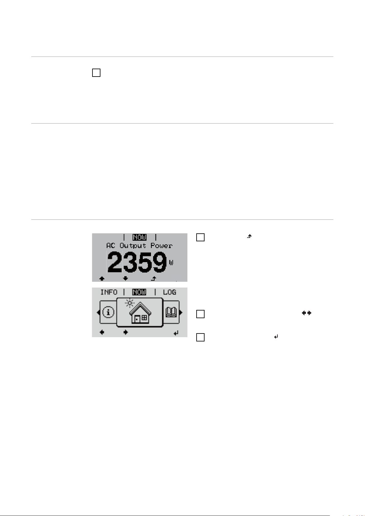
menu level
Press any key
1
The display backlighting is activated.
There is an option under "Display Settings - Backlighting" in the SETUP menu
to set the display backlighting so that it is on all the time or off all the time.
If two minutes pass without any button being pressed, the display backlighting
switches off automatically and the inverter goes to the "NOW" menu item (assuming the display backlighting is set to AUTO).
The automatic selection of the "NOW" menu item can happen from any position
on the menu level, unless the inverter was manually switched into the "Standby"
operating mode.
After automatically selecting the "NOW" menu item, the current power of feeding in is displayed.
1
Press "ESC"
The display switches to the menu level.
2
Using the "Left" or "Right" keys select the desired menu item
3
Press the "Enter" key to select the
desired menu item
The menu items
NOW
-
Displays real-time values
LOG
-
Data recorded today, during the current calendar year and since the inverter
was started for the first time
GRAPH
-
Day characteristic displays a plot showing the output power during the day.
The time axis is scaled automatically. Press the "Back" key to close the display
SETUP
-
Setup menu
INFO
-
Information about the device and the software
52

Values displayed
under the NOW
menu item
Output power (W)
AC reactive power (VAr)
Grid voltage (V)
Output current (A)
Grid frequency (Hz)
Solar voltage (V) – Of U PV
Solar current (A) – Of I PV
Time Date
EN
Values displayed
under the LOG
menu item
Energy fed in (kWh / MWh)
Energy delivered by the inverter over the period in question
There may be discrepancies compared with values displayed on other measuring instruments because of differences in measuring methods. As far as the
billing of the energy fed in is concerned, the only binding display values are
those produced by the calibrated measuring instrument provided by the utility
company.
Max. output power (W)
Largest amount of energy delivered by the inverter during the period in question
Yield
Amount of money earned during the period in question (currency and conversion factor can be selected in the Setup menu)
Like the "Energy fed in" figure, the yield figure may also exhibit discrepancies
compared with other measured values.
The "Setup menu" section explains how to select a currency and charge rate.
The factory setting depends on the respective country setup.
Max. grid voltage (V)
Highest grid voltage measured during the period in question
Maximum solar voltage (V)
Highest solar module voltage measured during the period in question
Operating hours
Length of time the inverter has been working (HH:MM)
IMPORTANT! In order for the day and year values to be displayed correctly,
the time must be set accurately.
Alternative operating hours
Operating time of the inverter (HH:MM) in alternative mode (emergency power
mode).
53

Menu items in the Set-up menu
Standby Manual activation / deactivation of Standby mode
No energy is fed into the grid.
-
The Startup LED will show steady orange.
-
In the display, STANDBY / ENTER are alternately displayed
-
In Standby mode, no other menu item at menu level can be accessed or ad-
-
justed.
The automatic switchover into the "NOW" display mode after 2 minutes of
-
keyboard inactivity does not occur.
Standby mode can only be terminated manually by pressing the "Enter" key.
-
Pressing "Enter" at any time will cause energy to resume feeding into the
-
grid, as long as there is no error (state code)
Switching off Standby mode (manually switching off feeding energy into the
grid):
Select the "Standby" item
1
2
Press "Enter" function key
"STANDBY" and "ENTER" appear alternately on the display.
Standby mode is now active.
The Startup LED shows steady orange.
WiFi Access
Point
Resuming feeding energy into the grid:
In standby mode, the display alternates between 'STANDBY' and 'ENTER'.
1
Press the "Enter" function key to resume feeding energy into the grid
The "Standby" menu item is displayed.
At the same time, the inverter enters the startup phase.
The operating state LED shows steady green when feeding energy into the grid
has been resumed.
Activating / deactivating the WiFi Access Point. This is necessary for setting up
or adjusting system monitoring using the Datamanager web interface, for example. If no Datamanager is detected by the inverter, [not available] is displayed
Setting range WiFi Access Point
[stopped]
Activate WiFi AP?
To activate the WiFi Access Point Press the "Enter"
key
WiFi Access Point
[active]
54
The SS-ID (SS) and password (PW) are displayed.
Deactivate WiFi AP?
To deactivate the WiFi Access Point Press the
"Enter" key

WiFi Access Point
[not available]
EN
Displayed if there is no system monitoring present on
the inverter.
Relay (floating
contact switch)
Status codes (state codes), the status of the inverter (e.g. feeding energy into the
grid) or Energy Manager functions can be displayed using the floating switch contact (relay).
Setting range Relay mode / Relay test / Switch-on point* / Switch-off
point*
* these are only shown if the "E-Manager" function has been activated under "Relay mode".
Relay mode
The following functions can be shown using relay mode:
Alarm function (Permanent / ALL / GAF)
-
Active output (ON / OFF)
-
Energy Manager (E-Manager)
-
Setting range ALL / Permanent / GAF / OFF / ON / E-Manager
Factory setting ALL
Alarm function:
ALL / Permanent:
Switching the floating switch contact for permanent and temporary service codes (e.g. brief interruption to energy being
fed into the grid, a service code occurs a certain number of
times a day - can be adjusted in the "BASIC" menu)
GAF As soon as GAF mode is selected, the relay is switched on.
The relay opens as soon as the power stage set registers an
error and goes from normally feeding energy into the grid to
being in an error state. This means that the relay can be used
for fail-safe functions.
Application example
It may be necessary to perform phase compensation when using a single-phase inverter at a multiphase site. If an error occurs on one or several inverters and the connection to the grid
is broken, the other inverters must also be disconnected to
maintain the phase balance. The "GAF" relay function can be
used in conjunction with the Datamanager or an external protection device to recognise or signal that an inverter is not
feeding in or is disconnected from the grid and to then disconnect the remaining inverters from the grid using a telecontrol command.
Active output:
ON: The floating NO contact is on all the time the inverter is in op-
eration (as long as the display is not dark or is displaying
something).
OFF: The floating NO contact is off.
55

Energy Manager:
E-Manager: Further details on the "Energy Manager" function may be
found in the "Energy Manager" section.
Relay test
Function test to determine whether the floating switch contact switches
Switch-on point (only if "Energy Manager" function is activated)
for setting the effective power limit beyond which the floating switch contact is
switched on
Factory setting 1000 W
Setting range Set switch-off point up to the maximum nominal output
of the inverter (W or kW)
Switch-off point (only if "Energy Manager" function is activated)
for setting the effective power limit beyond which the floating switch contact is
switched off
Factory setting 500
Setting range 0 to the set switch-on point of the inverter (W or kW)
Energy Manager
(under "Relay"
menu item)
The "Energy Manager" function can be used to activate the floating switch con-
tact in such a way that it functions as an actuator.
Thus, a load that is connected to the floating switch contact can be controlled by
specifying a switch-on or switch-off point that depends on the power of feeding
in.
The floating switch contact is automatically switched off:
If the inverter is not feeding any power into the grid
-
If the inverter is manually switched to Standby mode
-
If the effective power is set to < 10% of the rated power
-
To activate the "Energy Manager" function, select "E-Manager" and press the
"Enter" key.
When the "Energy Manager" function is running, the "Energy Manager" symbol
will appear in the top left corner of the display:
When the floating NO contact is off (open contact)
When the floating NO contact is on (closed contact)
To deactivate the "Energy Manager" function, select a different function and
press the "Enter" key.
Notes on setting up the switch-on and switch-off points
The interface of the energy management relay always uses the output power of
the inverter as a reference point, although this will not necessarily match what is
generated by the PV system in the case of the hybrid system.
If the difference between the switch-on and switch-off points is too small, or if
there are fluctuations in effective power, the result may be multiple switching
cycles
To avoid frequent switching on and off, the difference between the switch-on and
switch-off points should be at least 100 - 200 W.
56

When choosing the switch-off point, the power consumption of the connected
load should be taken into account.
When choosing the switch-on point, the weather conditions and anticipated insolation should also be taken into account.
Application example
Switch-on point = 2000 W, switch-off point = 1800 W
If the inverter is outputting 2000 W or above, then the floating switch contact on
the inverter is switched on.
If the inverter output falls to below 1800 W, the floating switch contact is
switched off.
Possible applications:
Operating a heat pump or an air-conditioning system using as much self-generated power as possible
Time / Date Set the time, date and automatic changeover between summer and winter time
Setting range Set time / Set date / Time display format / Date display
format / Summer/winter time
EN
Set time
Set the time (hh:mm:ss or hh:mm am/pm – depending on the setting for the time
display format)
Set date
Set the date (dd.mm.yyyy or mm/dd/yyyy - depending on the setting for the date
display format)
Time display format
For specifying the time display format
Setting range 12hrs / 24hrs
Factory setting Depends on country setup
Date display format
For specifying the date display format
Setting range mm/dd/yyyy / dd.mm.yy
Factory setting Depends on country setup
Summer/winter time
Activate/deactivate automatic changeover between summer and winter time
Setting range on / off
Factory setting on
IMPORTANT! The time and date must be set accurately in order for the day and
year values and for the day characteristic to be displayed correctly.
57

Display settings
Setting range Language / Contrast / Illumination
Language
Set language for display
Setting range German, English, French, Dutch, Italian, Spanish,
Czech, Slovak, etc.
Contrast
Set the contrast on the display
Setting range 0 - 10
Factory setting 5
Since the contrast is temperature-dependent, it may be necessary to adjust the
setting under the "Contrast" menu item when the environmental conditions
change.
Illumination
Initial setting for display illumination
The "Illumination" menu item only relates to the display backlighting.
Setting range AUTO / ON / OFF
Factory setting AUTO
AUTO: The display backlighting is activated by pressing any key. If no key is
pressed for 2 minutes, the display backlighting will go off again.
ON: The display backlighting remains permanently on when the inverter
is active.
OFF: The display backlighting is permanently switched off.
ENERGY YIELD The following settings can be changed/set here:
Counter deviation / Calibration
-
Currency
-
Feed-in tariff
-
CO2 factor
-
Setting range Currency / Feed-in tariff
Counter deviation / calibration
Calibrating the counter
58
Currency
Set the currency
Setting range 3 characters, A-Z
Feed-in tariff
Set the remuneration rate for energy fed into the grid

Setting range 2 digits, 3 decimal places
Factory setting (depends on country setup)
CO2 factor
Setting the CO2 factor of the energy fed into the grid
Fan To check that the fan is working correctly
Setting range Test fan #1 / Test fan #2 (depending on the device)
Use the "Up" and "Down" keys to select the desired fan
-
Testing of the selected fan is initiated by clicking "Enter".
-
The fan will continue to run until the operator exits the menu by pressing
-
"Esc".
IMPORTANT! Nothing will show on the inverter display if the fan is working. The
only way to check how the fan is working is by listening and feeling.
EN
59
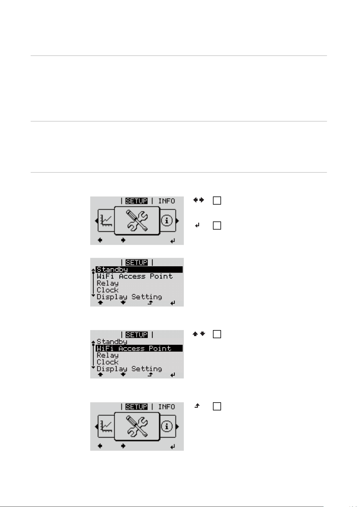
SETUP menu item
GRAPH
GRAPH
Initial setting The inverter is pre-configured after commissioning has been completely carried
out (e.g. using the Installation Wizard) according to the country setup.
The SETUP menu item allows the initial settings of the inverter to be changed
easily to bring it in line, as closely as possible, with the preferences and requirements of the user.
Software updates
Navigating the
SETUP menu
item
IMPORTANT! As a result of software updates, you may find that your device has
certain functions that are not described in these Operating Instructions, or vice
versa. Certain illustrations may also differ slightly from the actual controls on
your device, but these controls function in exactly the same way.
Entering the SETUP menu item
At the menu level, use the “Left”
1
or “Right” keys to select the
“SETUP” menu item
Press the "Enter" key
2
The first entry under the SETUP
menu item is displayed:
"Standby"
60
Scrolling between the entries
Exiting an entry
If no key is pressed for 2 minutes:
Use the "Up" and "Down" keys to
3
move between the available
entries
To exit a menu entry, press the
4
"Back" key
The menu level appears

The inverter switches from wherever it is on the menu level back to the
Relay
Standby
Relay
Clock
Display Setting
Energy Yield
-
"NOW" display mode (exception: "Standby" Setup menu item).
The display backlighting goes out.
-
The current power of feeding in is displayed.
-
EN
Setting menu
entries, general
Open the desired menu
1
2
Use the 'Up' or 'Down' keys to select the desired menu item
3
Press "Enter"
The available settings are displayed: The first digit of a value to be set
flashes:
Use the 'Up' or 'Down' buttons to
4
select the desired setting
Press the 'Enter' key to save and
5
Use the 'Up' or 'Down' keys to se-
4
lect a value for the first digit
5
Press "Enter"
apply the setting.
The second digit of the value flashes.
To discard the setting, press the
Repeat steps 4 and 5 until ...
'Esc' key.
6
the whole value to be set flashes.
7
Press "Enter"
Repeat steps 4 - 6 as required for
8
units or other values that are to
be set until the appropriate unit
or the value flashes.
Press the 'Enter' key to save and
9
apply the changes.
Application example: Setting
the time
The currently selected menu item is
displayed.
To discard the changes, press the
'Esc' key.
The currently selected menu item is
displayed.
Select “Time / Date” from the
1
Setup menu.
Press the “Enter” key.
2
61

An overview of the values that can
Relay
Standby
Relay
Clock
Display Setting
Energy Yield
be changed is displayed.
Use the “Up” or “Down” keys to
3
select “Set time”.
Press the “Enter” key.
4
The current time appears.
(HH:MM:SS, 24-hour clock),
the “tens” digit for the hour will
flash.
Use the “Up” and “Down” keys to
5
select a value for the “tens” digit
of the hour.
Press the “Enter” key.
6
The “units” digit for the hour will
flash.
Repeat steps 5 and 6 to set the
7
“units” digit for the hour, for the
minutes and for the seconds until...
the set time starts flashing.
Press the “Enter” key.
8
The time is applied and the overview
of values that can be changed is displayed.
Press the “Esc” key.
4
The “Time / Date” item on the Setup
menu appears.
62

The INFO menu item
Measured values PV ins.
Insulation resistance of the photovoltaic system and the storage system
Ext. lim.
External power reduction in per cent e.g. specified by grid operator
U PV
Current PV voltage on the terminals even if the inverter is feeding in no power
whatsoever
GVDPR
Grid voltage-dependent power reduction
Fan #1
Percentage of target output for fan
PSS status IMPORTANT! Due to the low level of insolation early in the morning and in the
evening, the status codes STATE 306 (Power low) and STATE 307 (DC low) are
displayed routinely at these times of day. These status codes do not indicate any
kind of fault at this point in time.
EN
The status of the most recent inverter fault can be displayed.
Press the "Enter" key to see the status of the power stage set and the most
-
recent fault
Use the "Up" and "Down" keys to scroll through the list
-
Press the "Back" key to close the status and fault list
-
Grid status The five most recent grid faults can be displayed:
Press the 'Enter' key to see the five most recent grid faults
-
Use the 'Up' and 'Down' keys to scroll through the list
-
Press the 'Back' key to close the grid fault display
-
Device information
For displaying the settings that will be of relevance to a power supply company.
The values shown will depend on the country setup or the device-specific settings of the inverter.
Display area General / Country-specific setting / MPP tracker / Grid
monitoring / Grid voltage limits / Grid frequency limits /
Q-mode / AC power limit / AC voltage derating / Fault
Ride Through
General: Device type
Fam.
63

Country-specific
setting:
MPP Tracker: PV Tracker
Grid monitoring: GMTi
Grid voltage limits: UILmax
Setup
Specified country setup
Version
Version of country setup
Alternative (emergency power) or original country setup
activated
Group
Group for updating the inverter software
Start-up time of inverter in s
GMTr
reconnection time in s following a grid fault
ULL
Mean grid voltage over 10 minutes in V
LLTrip
Trip time for long-term voltage monitoring
Upper inner grid voltage in V
UILmin
Lower inner grid voltage in V
Grid frequency limits:
Q-mode: Current cos phi power factor setting
AC power limit: Max. P AC
AC voltage derating: Status
FILmax
Upper inner grid frequency in Hz
FILmin
Lower inner grid frequency in Hz
(e.g. Constant Cos(phi) / Constant Q / Q(U) characteristic / etc.)
Manual power reduction
ON / OFF – Voltage-dependent power reduction
GVDPRe
Threshold at which the voltage-dependent power reduction begins
GVDPRv
Reduction gradient used to reduce the power, e.g.: 10%
per volt above the GVDPRe threshold
64
Message
Activates the sending of an info message via Fronius
Solar Net

Fault Ride Through: Status – Default setting: OFF
If the function is activated, the inverter does not switch
off immediately in the event of a short-term AC voltage
dip (outside of the limits specified by the grid supplier),
but instead continues to feed in power for a defined
period.
DB min – Default setting: 90%
"Dead Band Minimum" setting in per cent
DB max - Default setting: 120%
"Dead Band Maximum" setting in per cent
k-Fac. - Default setting: 0
Version Displays the version and serial numbers of the PC boards in the inverter (e.g. for
service purposes)
Display area Display / Display Software / Integrity Checksum /
Memory Card / Memory Card #1 / Power Stage / Power
Stage Software / EMI Filter / Power Stage #3 / Power
Stage #4
EN
65

Switching the key lock on and off
Acess Code
General The inverter has a key lock function.
When the key lock is active, the Setup menu is not accessible, i.e. the setup data
cannot be changed accidentally (or maliciously).
The code 12321 has to be entered in order to activate / deactivate the key lock.
Switching the
key lock on and
off
1
Press the "Menu" key
The menu level appears.
Press the unassigned "Menu / Esc" key
2
5 times
"Access Code" is displayed in the "CODE"
menu; the first digit starts flashing.
Enter the code 12321: Use the "Plus" and
3
"Minus" keys to select a value for the
first digit of the code
4
Press the "Enter" key
The second digit flashes.
Repeat steps 3 and 4 for the second,
5
third, fourth and fifth digits of the access
code until...
the selected code starts flashing.
6
Press the "Enter" key
"Setup Menu Lock" is displayed in the
"LOCK" menu.
7
Use the "Plus" and "Minus" keys to
turn the key lock on or off:
ON = key lock is on (the Setup menu is
not accessible)
OFF = key lock is off (the Setup menu is
accessible)
8
Press the "Enter" key
66
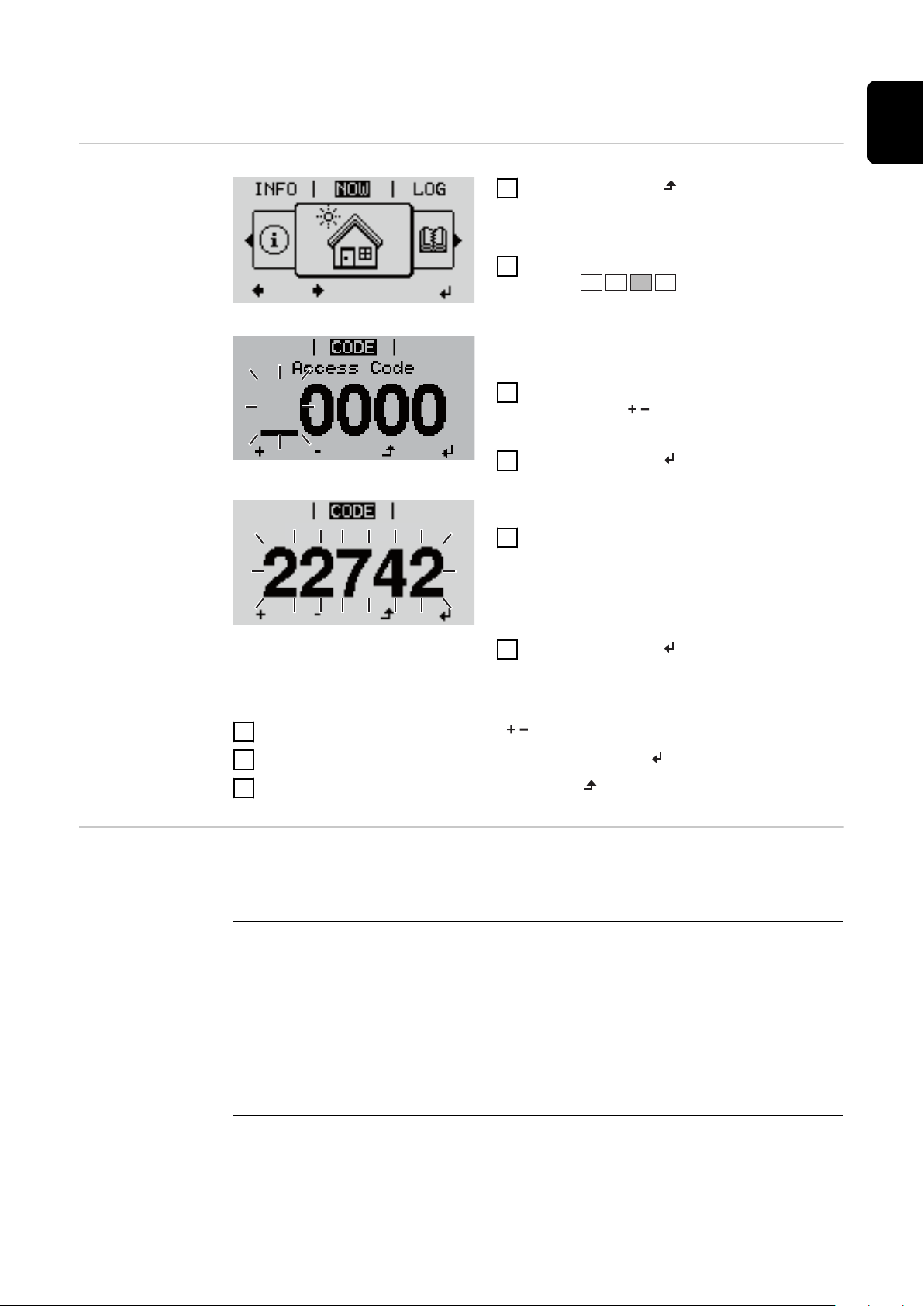
The Basic menu
Access Code
EN
Access the Basic
menu
1
Press the "Menu” button
The menu level appears.
Press the unassigned "Menu / Esc" key
2
5 times
"Access Code" is displayed in the "CODE"
menu; the first digit starts flashing.
Enter the code 22742: Use the "Plus" and
3
"Minus" keys to select a value for the
first digit of the code
4
Press the "Enter" button
The second digit flashes.
Repeat steps 3 and 4 for the second,
5
third, fourth and fifth digits of the access
code until...
the selected code starts flashing.
Items on the Basic menu
6
Press the "Enter" button
The Basic menu appears.
7
Use the "Plus" and "Minus" keys to select the desired entry
8
Edit the desired menu item by pressing the "Enter" button
9
Press the "Esc" key to exit the Basic menu
The Basic menu is used to set the following parameters, which are important
for installing and operating the inverter:
MPP Tracker 1
DC operating mode: MPP AUTO / FIX / MPP USER
-
MPP AUTO: normal operating status; the inverter automatically
-
searches for the ideal operating point
FIX: for entering a fixed DC voltage at which the inverter will operate
-
MPP USER: for entering a lower MP voltage above which the inverter
-
will search for its ideal operating point
Dynamic Peak Manager: ON / OFF
-
Fixed voltage: for entering a fixed voltage (150 - 800 V)
-
MPPT start voltage: for entering the start voltage (150 - 800 V)
-
67

Input signal
Function of the: Ext Sig. / S0-Meter / OFF
-
Only with the Ext Sig.: function selected:
Triggering method: Warning (warning shown on display) / Ext. Stop
-
(inverter switches off)
Connection type: N/C (normally closed contact) / N/O (normally open
-
contact)
SMS / relay
Event delay:
-
for entering the time delay after which an SMS is sent or the relay is to
switch
900 - 86,400 seconds
Event counter:
-
for entering the number of events that lead to signalling:
10 - 255
Insulation setting
Insulation warning: ON / OFF
-
Threshold warning: for entering a threshold that leads to a warning
-
Threshold fault: for entering a threshold that leads to a fault (not avail-
-
able in all countries)
Both the PV system and the battery are monitored
-
Temperature warning
For activating/deactivating the overtemperature warning for each event
ON / OFF
TOTAL Reset
Under the LOG menu item, this setting resets the max. and min. voltage values
and the max. power of feeding in to zero.
Once the values have been reset, this action cannot be undone.
To reset the values to zero, press the "Enter" key.
"CONFIRM" is displayed.
Press "Enter" again.
The values are reset and the menu is displayed
68

Fronius system monitoring
69

70

General
General Fronius system monitoring is a networked datalogger.
The Fronius system monitoring web page provides a quick overview of the photovoltaic system.
It can be accessed via a web browser when there is a direct connection or – if
configured to support an indirect connection – over the Internet.
If the feature is used in conjunction with Fronius Solar.web, current data and
archive data can be accessed for a particular photovoltaic system via the Internet or the Fronius Solar.web App without the need for any laborious configuration work. Fronius system monitoring automatically sends the data to Fronius
Solar.web.
EN
Prerequisites for
operation
You must have a suitable internet connection to enable data to be exchanged
smoothly over the internet:
For wired internet solutions, Fronius recommends a
-
download speed of at least 512 kBit/s and an
upload speed of at least 256 kBit/s.
For solutions that rely on mobile internet services, Fronius recommends 3G
-
transmission as a minimum, plus a reliable signal.
Even if these specifications are adhered to, there is still no guarantee that
everything will run smoothly.
High error rates during transmission, variable reception conditions or transmission dropouts can all have a detrimental effect on the online functionality of
Fronius system monitoring.
Fronius recommends testing any connections that meet the minimum requirements locally.
71

Calculating data volumes
General When using Fronius system monitoring, data is collated that must be transmitted
over the internet.
The data volume must be calculated so that the correct internet connection is
selected.
The data volume calculation below provides an overview of the data quantities involved when using Fronius system monitoring.
Calculating data
volumes
The data volume calculation depends on the number of connected devices in the
system monitoring.
The table below provides an overview of the data volume for various configurations and time settings (INV = Fronius Symo Hybrid, SM = Smart Meter, BAT =
battery module of the Fronius Solar Battery)
Data volume per day:
Sent Configuration 5 min logging 30 min logging
Hourly
(06:00 20:00)
Daily INV 30 kB 15 kB
INV 436 kB 305 kB
INV + SM 659 kB 349 kB
INV + SM + 3x BAT 2198 kB 605 kB
INV + SM + 4x BAT 2556 kB 659 kB
INV + SM + 5x BAT 2958 kB 750 kB
INV + SM + 6x BAT 3306 kB 775 kB
INV + SM + 7x BAT 3485 kB 838 kB
INV + SM + 8x BAT 4160 kB 920 kB
INV + SM 55 kB 20 kB
INV + SM + 3x BAT 228 kB 49 kB
72
INV + SM + 4x BAT 262 kB 53 kB
INV + SM + 5x BAT 305 kB 63 kB
INV + SM + 6x BAT 344 kB 68 kB
INV + SM + 7x BAT 388 kB 73 kB
INV + SM + 8x BAT 426 kB 83 kB

Data volume per month:
Sent Configuration 5 min logging 30 min logging
Hourly
(06:00 20:00)
Daily INV 1 MB 1 MB
INV 13 MB 10 MB
INV + SM 20 MB 11 MB
INV + SM + 3x BAT 67 MB 19 MB
INV + SM + 4x BAT 78 MB 20 MB
INV + SM + 5x BAT 90 MB 23 MB
INV + SM + 6x BAT 101 MB 24 MB
INV + SM + 7x BAT 106 MB 26 MB
INV + SM + 8x BAT 126 MB 28 MB
INV + SM 2 MB 1 MB
INV + SM + 3x BAT 7 MB 2 MB
INV + SM + 4x BAT 8 MB 2 MB
INV + SM + 5x BAT 10 MB 2 MB
INV + SM + 6x BAT 11 MB 3 MB
INV + SM + 7x BAT 12 MB 3 MB
INV + SM + 8x BAT 13 MB 3 MB
EN
A data volume of approx. 500 kB per hour is required to view the system on
Fronius Solar.web or the Fronius Solar.web App.
A certain data volume is also required to update the Fronius system monitoring
firmware. This data volume depends on the size of the update package and therefore cannot be considered in the advance data volume calculation.
If data is sent via a third-party service (e.g. push service), a large quantity of data
may be involved.
IMPORTANT! Fronius recommends a flat rate data connection to avoid high con-
nection charges.
73

General information for the network administrator
Requirements NOTE! Knowledge of networking systems is required in order to configure Froni-
us system monitoring for the network.
If you are integrating Fronius system monitoring into an existing network, you
must adapt the address settings in line with the network.
e.g.: Network address space = 192.168.1.x, subnet mask = 255.255.255.0
An IP address of between 192.168.1.1 and 192.168.1.254 must be assigned
-
to Fronius system monitoring.
The selected IP address must not be in use on the network already.
-
The subnet mask must match that of the existing network (e.g.
-
255.255.255.0).
If you want Fronius system monitoring to send service messages or to transmit
data to Fronius Solar.web, you must enter a gateway address and a DNS server
address. Fronius system monitoring uses the gateway address for the purpose of
establishing an Internet connection. An example of a suitable gateway address
would be the IP address of the DSL router.
General firewall
settings
IMPORTANT!
Fronius system monitoring must never be assigned the same IP address as
-
the PC/laptop itself!
Fronius system monitoring is not capable of connecting to the Internet on its
-
own. In the case of a DSL connection, a router has to establish the Internet
connection.
DSL routers usually allow data to be sent over the internet and so do not normally have to be configured for this purpose.
Server addresses for data transfer
If a firewall is used for outgoing connections, the following protocols, server addresses and ports must be allowed for successful data transfer:
Tcp fronius-se-iot.azure-devices.net:8883
-
Tcp fronius-se-iot.azure-devices.net:443
-
Tcp fronius-se-iot-telemetry.azure-devices.net:8883
-
Tcp fronius-se-iot-telemetry.azure-devices.net:443
-
Udp sera-gen24.fronius.com:1194 (213.33.117.120:1194)
-
Tcp froniusseiot.blob.core.windows.net:443
-
Tcp provisioning.solarweb.com:443
-
Tcp cure-se.fronius.com:443
-
NTP 0.time.fronius.com
-
Tcp http://firmware-download.fronius.com:80
-
Upd/Tcp 0.time.fronius.com:123
-
74
If existing firewall rules block the connection to the Fronius system monitoring
function, the following firewall rules must be added:

49049/UDP
80/TCP *)
Using Fronius
Solar.web and
sending service
messages
output
Sending of service messages x -
Ability to connect to Datamanager via Fronius
Solar.web
Ability to connect to Datamanager via Fronius
Solar.access or Fronius Solar.service
Ability to access the Datamanager web page - x
Configure the firewall so that data can be sent from the Fronius system monitoring IP address to port 49049/UDP of "fdmp.solarweb.com".
*) We recommend only allowing access to the web interface of the Fronius system monitoring function from secure networks. If internet access is absolutely
necessary (e.g. for service purposes within a defined time period), configure the
network router in such a way that requests for any external port are redirected to
port 80/TCP.
Caution - the inverter will therefore be visible on the internet and at will be at an
increased risk of network attacks.
An Internet connection is required if you want to use Fronius Solar.web or to
send service messages.
Fronius system monitoring is not capable of connecting to the Internet on its
own. In the case of a DSL connection, a router has to establish the Internet connection.
x -
- x
Input
EN
75

Installing Fronius system monitoring – Overview
Relay
Standby
WiFi Access Point
Relay
Clock
Display Setting
Safety
Starting for the
first time
WARNING!
Danger from incorrect operation
This can result in severe personal injury and damage to property.
Do not use the functions described here until you have fully read and under-
▶
stood the Operating Instructions of every system component:
Do not use the functions described here until you have read and understood
▶
all the safety rules.
IMPORTANT! Knowledge of networking systems is required in order to install
Fronius system monitoring.
IMPORTANT! Starting up the Fronius system monitoring function for the first
time is made considerably easier with the Fronius Solar.start app. The Fronius
Solar.start app is available in the respective app stores.
Or visit
https://wizard.solarweb.com to select the desired menu item
IMPORTANT! In order to establish a connection to Fronius system monitoring,
the end device in question (e.g. laptop, tablet, etc.) must be set up as follows:
"Obtain IP address automatically (DHCP)" must be activated
-
Switch the device to Service mode
1
Activate the WLAN Access Point via the Setup menu on the inverter
-
The inverter establishes the WLAN access point. The WLAN access point remains open for 1 hour.
76
Installation using the Solar.start
app
Download the Fronius Solar.start
2
App
Installation using a web browser
Connect the end device to the
2
WLAN access point
SSID = FRONIUS_239.xxxxx (4-8
digits)
Search for a network with the
-
name "FRONIUS_239.xxxxx"
Establish a connection to this
-
network
Enter the password 12345678
-
EN
Run the Fronius Solar.start app
3
The Setup wizard start page is displayed.
(Alternatively, connect the end
device and inverter using an Ethernet cable.)
Enter the following in the
3
browser:
http://datamanager
or
192.168.250.181 (IP address for
WLAN connection)
or
169.254.0.180 (IP address for
LAN connection)
If you run the technician wizard, always remember to make a note of the assigned
service password. This service password is required to enter settings in the "System overview" and "DNO Editor" menus as well as for advanced battery settings.
If the technician wizard is not run, no specifications regarding power reduction
are set and hybrid mode is not possible (charging and discharging of the battery)
Run the technician wizard and follow the instructions
4
77

IMPORTANT!
Danger of deep discharge of an unactivated battery
This may result in permanent damage to the battery.
The Solar Web wizard needs to be run in order to activate the battery and, if
▶
necessary, the Smart Meter.
Run the Solar Web wizard and follow the instructions
5
The Fronius Solar.start homepage
or
the Fronius system monitoring web page is displayed.
Information to
help you work
through the
technician wizard
The technician wizard consists of 5 steps:
1. General
General system data (e.g. system name) is entered here
2. Service password
Enter (and make a note of) the service password.
3. IO assignment
Settings for the IO interface are entered (see also General for IO assignment on
page 96)
4. System overview
Settings for the entire PV system are entered (see also System overview on page
111)
5. Dynamic power
Settings for dynamic power reduction are entered (see also DNO Editor – Dy-
namic power reduction on page 116)
Once you have worked your way through the technician wizard, an automatic process is triggered to calibrate all the components. This involves charging the
Fronius Solar Battery fully. After that, the system automatically starts in the set
operating mode.
This calibration charging process is also performed automatically during actual
operation after a number of charging and discharging cycles. When this calibration charge is performed depends on a number of different factors, such as the
average state of charge or the energy throughput through the battery. The time
can therefore vary depending on the time of year as well.
78
If the "permit battery charging from DNO grid" setting is deactivated, this calibration charging process relies exclusively on energy from the photovoltaic system
when operating under normal conditions. Depending on the insolation conditions
and size of the systems concerned, the charging process can take a very long
time.
If the "permit battery charging from DNO grid" setting is activated, the calibration charging process is performed by drawing a constant current from the
photovoltaic system and the DNO grid.
IMPORTANT! The automatic process for fully charging the battery may result in
energy being drawn from the DNO grid. The process can take several hours and
cannot be aborted.

Testing backup
power mode
NOTE!
Danger from immediate inverter operation in backup power mode without a connection to the grid having been previously established.
During grid-connected operation, the inverter recognises and stores the direction
of phase rotation in the household network.
Without a grid connection, no information is available regarding the direction of
rotation and the inverter feeds energy with a default direction of rotation.
This can cause the three-phase consumers in the household network to experience errors.
Backup power mode should be tested once it has been installed and set up for
the first time. A battery state of charge of over 30% is recommended when in
test mode.
A description of how to perform the test operation can be found in the chapter
"Backup power checklist" of the document "Fronius Energy Package - Examples
of backup power switchover".
EN
79
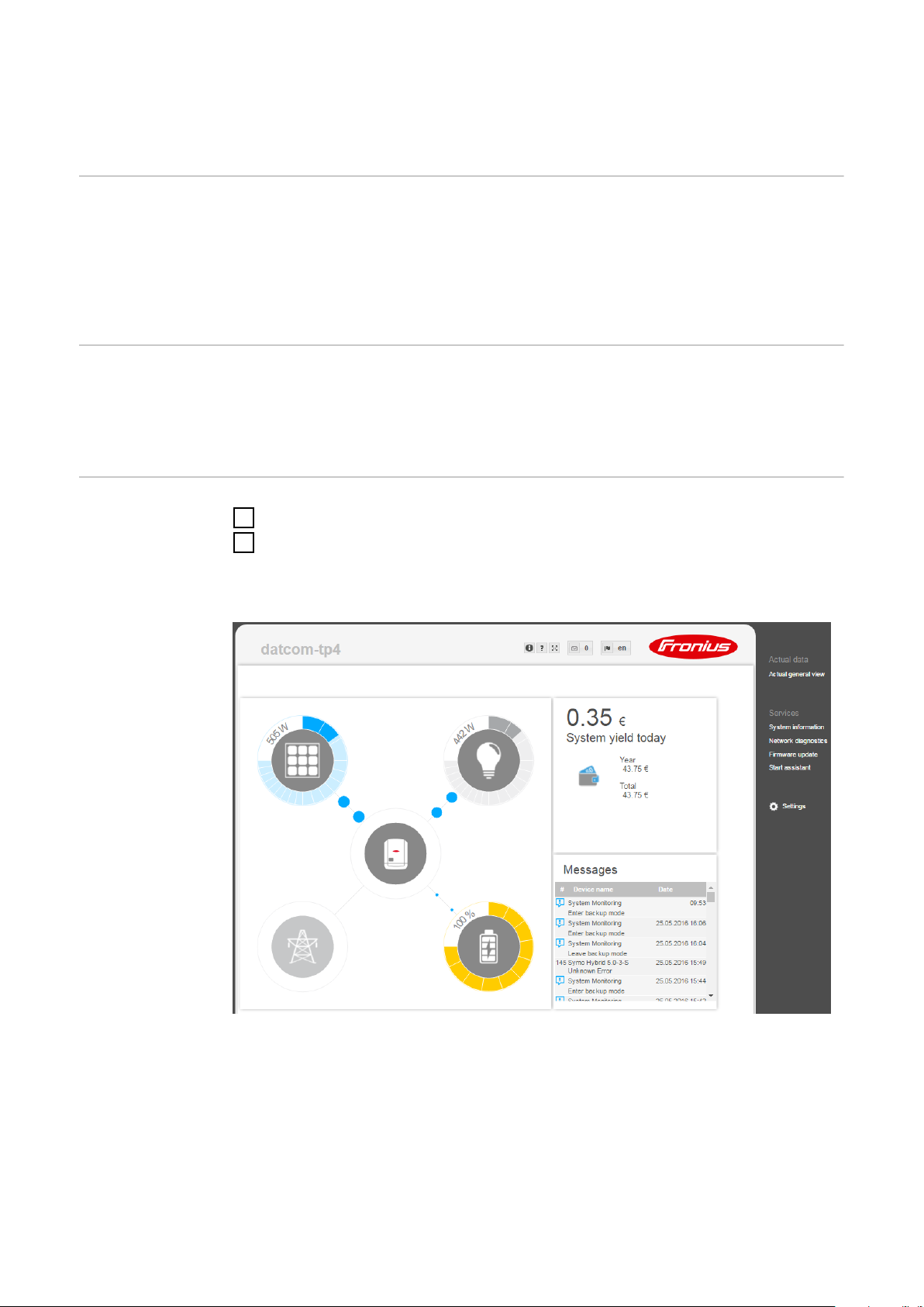
Connecting to Fronius system monitoring via a
web browser
General remarks A connection to Fronius system monitoring via a web browser is the ideal choice
if there are lots of PC users who need to access the latest system values over the
same LAN (e.g. company networks, schools, etc.).
The Fronius system monitoring web page shows the current power flow in the hybrid system.
Prerequisites
Establishing a
connection to
Fronius system
monitoring via a
web browser
LAN or WLAN connection as a minimum
-
Web browser (e.g. Microsoft Internet Explorer IE >/= 9.0, Firefox 4, Google
-
Chrome 27.0, etc.)
PC/laptop on the same network segment as Fronius system monitoring
-
Open the web browser.
1
In the address field, enter the IP address or the host name and domain name
2
of the Fronius system monitoring.
The Fronius system monitoring web page appears.
80

Connecting to Fronius system monitoring established via the Internet and Fronius Solar.web
General remarks Archive and current data for a photovoltaic system can be accessed from any-
where in the world (provided that you have Internet access) by setting up a connection to Fronius system monitoring via the Internet and Fronius Solar.web.
With this setup, you can also invite other users to view the photovoltaic system
data as guests and you can compare several systems with one another.
Functional description
Prerequisites
Fronius system monitoring is connected to the Internet (e.g. via a DSL router).
Fronius system monitoring logs into Fronius Solar.web at regular intervals and
sends the saved data on a daily basis.
Fronius Solar.web can actively make contact with Fronius system monitoring, e.g.
for the purpose of displaying up-to-date data.
Internet access
-
Web browser
-
IMPORTANT! Fronius system monitoring is not capable of connecting to the
Internet on its own. In the case of a DSL connection, a router has to establish the Internet connection.
EN
Accessing Fronius system monitoring data via
the Internet and
Fronius Solar.web
The photovoltaic system must be registered with Fronius Solar.web.
-
Current data can only be accessed in Fronius Solar.web if “Send actual data
-
to Fronius Solar.web” is set to “Yes” under “Fronius Solar.web” in the settings
for Fronius system monitoring.
In order for archive data to be accessed in Fronius Solar.web, “Send archive
-
data to Fronius Solar.web” must be set to “daily” or “hourly” for Fronius system monitoring.
To use Fronius Solar.web for the purpose of accessing current data and archive
data recorded by Fronius system monitoring, proceed as follows:
Start Fronius Solar.web: http://www.solarweb.com
1
For detailed information on Fronius Solar.web, see the online help system.
81

82

Current data, services and settings
offered by Fronius system monitor-
ing
83

84

The Fronius system monitoring web page
(1)
(5)
(3)
(6)
(2)
(4)
EN
Fronius system
monitoring web
page – Overview
The Fronius system monitoring web page shows the following data:
(1)Additional settings
(2) System overview: displays the current power flow on the hybrid system
(3)System yield overview
(4)Overview of recent status codes
(5)System information, network diagnostics, firmware update
(6)The Settings menu
The Settings
menu
When you click "Settings", the Settings menu appears on the Fronius system
monitoring web page.
The "Settings" menu is where you configure Fronius system monitoring.
Setting and viewing "General" menu items
Establish a connection to Fronius system monitoring.
1
Click "Settings".
2
Click the required menu item.
3
The relevant menu item opens.
View the menu item or edit it as required.
4
If applicable, click the button for implementing the setting (e.g. Save, Syn-
5
chronise, etc.)
The edited data is applied.
85
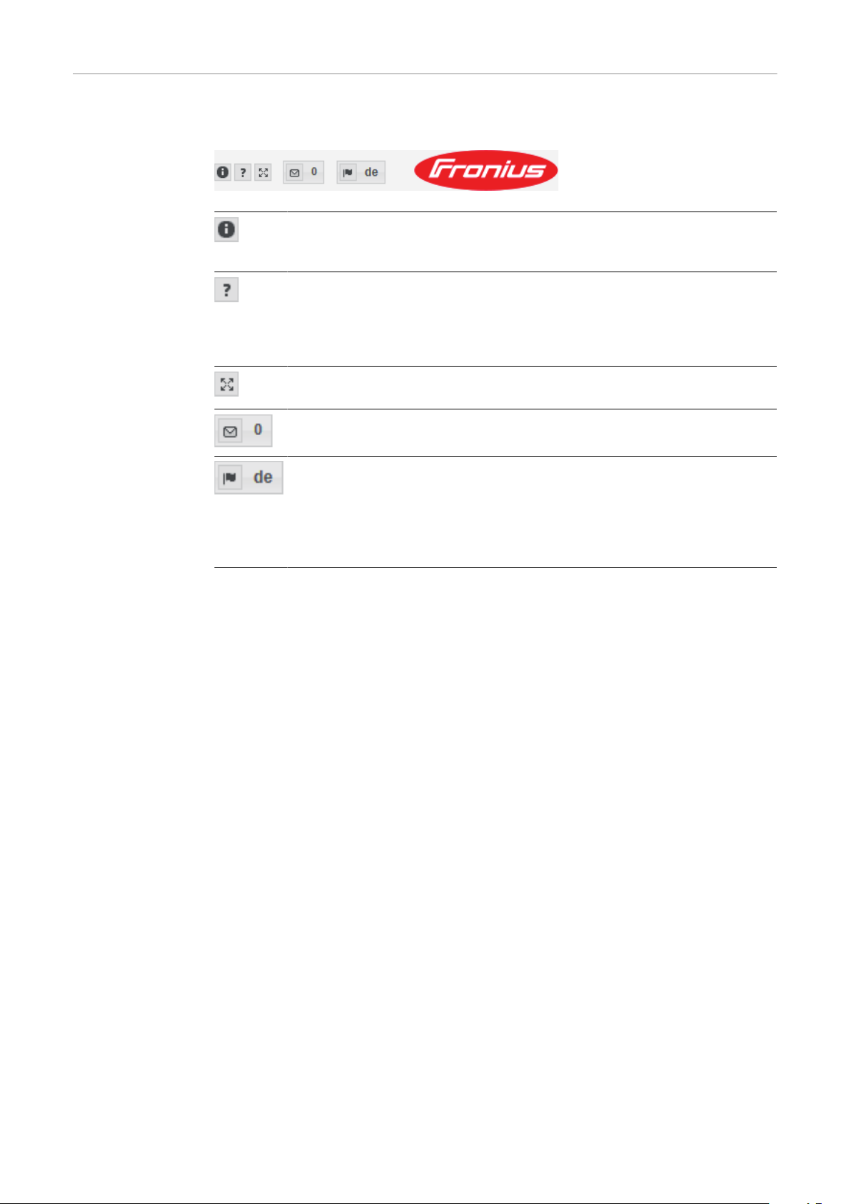
Additional setting options
On the Fronius system monitoring web page, the following additional setting options are available on the top right-hand side:
System information:
Datalogger ID, software version, hardware version, Fronius Solar.web
connection
Help:
Commissioning the LAN
-
Commissioning the WLAN
-
Software operating instructions
-
Fronius Solar channel
-
Expand contents:
Hides the area containing the Actual data/Settings menus
Display messages
Language:
For setting the language
The Fronius system monitoring web page is either displayed in the
same language as the current browser or in the language that was
last selected.
86

Services – System information
EN
System information
The system information page contains various information about the system.
Additionally, there are the following buttons:
"Datalogger restart"
-
For restarting the Datamanager / system monitoring
"Reset to factory settings" button with the selection options:
-
"All settings except for the network"
-
For resetting the Datamanager (system monitoring) to the factory settings.
The network settings and all the items protected by the service user
(DNO Editor, meter settings and the service password) are retained
"All settings"
-
For resetting the Datamanager (system monitoring) and the network settings to the factory settings.
All the items protected by the service user (DNO Editor, meter settings
and the service password) are retained
IMPORTANT! If the Datamanager (system monitoring) is reset to the factory settings, it is essential to check the time and date settings.
87

Services – Network diagnostics
Network diagnostics
Under Services / Network diagnostics, you will find various functions that are
useful for diagnosing and resolving network problems. You can execute ping and
traceroute commands.
Ping command
A ping command allows you to check whether a host can be reached and how
long the data transfer process takes.
Sending a ping command:
Enter a host name or an IP address in the Host: field
1
Click the ping button
2
The ping command is sent.
-
The identified data is displayed.
-
Traceroute command
You can use a traceroute command to determine which intermediate stations the
data passes through on its way to the host.
Sending a traceroute command:
Enter a host name or an IP address in the Host: field
1
Click the "traceroute" button
2
The traceroute command is sent.
-
The identified data is displayed.
-
88
Services – Firmware update
General The firmware of the Fronius system monitoring datalogger can be updated under
Services / Firmware update. A firmware update can be performed via a LAN or
over the Web.
EN
Searching for
updates automatically
Searching for
updates manually
Updating the
firmware via the
Web
IMPORTANT! An Internet connection is required to use the “Automatic update
search” function.
If the “Automatic update search” (1) option is activated, Fronius system monitoring automatically searches for updates once a day. If new updates are available, a
corresponding message is displayed alongside the additional setting options on
the Fronius system monitoring web page.
If the "Automatic update search" option is deactivated, the system does not
search for updates automatically.
To search for updates manually, press the "check now" button
1
Use your web browser to open the Fronius system monitoring web page.
1
Open “Firmware update” under “Services”.
2
Select 'Update via Web'
3
Click the 'Run update' button.
4
A confirmation prompt for the update is displayed.
Click the 'Yes' button
5
The update is performed and progress is indicated in the form of a bar and as
a percentage.
If the connection to the server fails:
Deactivate the firewall for the amount of time required to complete the up-
-
date.
Try again.
-
IMPORTANT! If a proxy server is being used to establish the Internet connection:
You must activate the “Use proxy server for Web update” option.
-
You must enter the data required.
-
89

Services – Starting the wizard
Starting the wizard
You can access and run the setup wizard again by selecting "Open wizards".
SOLAR WEB WIZARD
For connecting the system to Fronius Solar.web and Fronius apps for mobile
devices
TECHNICIAN WIZARD (for trained personnel or specialists only)
For system settings
FURTHER SETTINGS (for trained personnel or specialists only)
All settings for Fronius system monitoring. Click the "SOLAR WEB WIZARD"
button to return to the original page.
90

Settings – General
General Under "Yield", you can enter the charge rate per kWh ("Feed-in tariff"), the cur-
rency and the procurement costs per kWh ("Grid supply tariff") for calculating
the yield. The yield figure is displayed in the current general view.
Under "System time", you can enter the date, hour and minutes.
Click the "synchronisation" button to adapt the time that is displayed in the input fields of the Datamanager web page to the time on the operating system.
To apply the time, click the Apply/Save button
Under "Time zone settings", you can set the region and the town/city for the time
zone.
Fields marked with an asterisk * are mandatory.
EN
91

Settings – Passwords
General remarks Access to Fronius system monitoring is controlled by assigning passwords.
There are 3 different types of password available for this purpose:
The administrator password
-
The service password
-
The user password
-
Passwords Administrator password
User name = admin
The administrator password is set during the commissioning process and grants
the user read access and the right to change settings. The user can open the Settings menu and enter all settings apart from those for “DNO Editor” and "Meter".
If an administrator password has been set, the user must enter the user name
and password in order to open the Settings menu.
Service password
User name = service
The service password is usually assigned by the service technician or system installer when running the Setup wizard and it provides access to system-specific
parameters. The service password is required to modify meter and DNO Editor
settings. The "Meter" and "DNO Editor" menu items cannot be accessed unless a
service password has been assigned.
User password
When the 'Protect your system monitoring from unauthorized read access' se-
lection box is checked, the user password is displayed, user name = user.
If a user password has been assigned, the user only has read permissions. The
user is not able to open the “Settings” menu.
If a user password is assigned, the user is required to enter the user name and
password whenever they want to establish a connection.
92
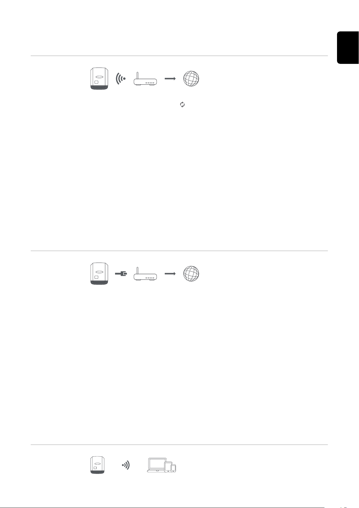
Settings – Network
EN
Internet via
WLAN
The networks found are displayed.
Clicking on the refresh button will carry out a second search of the available
WLAN networks.
Hidden networks can be added using the "Add WLAN" menu.
"Set" button - For saving a selected WLAN network.
Clicking the button opens the "WLAN Connection" window
"Delete" button - For deleting a saved WLAN network.
"Configure WLAN IP" button - After clicking the button, the "Configure IP" win-
dow opens with the same setting options as with a LAN connection.
"Connect via WPS" button - To access a WLAN via WPS without needing the
WLAN password:
1. Activate WPS on the WLAN router (see documentation provided with the
WLAN router)
2. Click the 'Connect via WPS' button
3. The WLAN connection is established automatically
Internet via LAN
Setting options:
"Obtain address" - statically
-
The user needs to enter a fixed IP address for the Datamanager (system
monitoring) and also defines the subnet mask, the gateway address and the
DNS server address (from the provider).
"Obtain address" - dynamically
-
The Datamanager (system monitoring) fetches the IP address from a DHCP
server (DHCP = Dynamic Host Configuration Protocol).
The DHCP server must be configured so that the same IP address is always
assigned to the Datamanager (system monitoring). This means that you always know which IP address can be used to reach the Datamanager (system
monitoring) datalogger.
If the DHCP server supports the DNS dynamic updates function, a name can
be assigned to the Datamanager (system monitoring) in the "Host name"
field. As a result, the connection to the Datamanager (system monitoring)
can be established using the name instead of the IP address.
For example: Host name = sample_system, domain name = fronius.com
The Datamanager (system monitoring) can be reached via the address
"sample_system.fronius.com".
Local network
via access point
93

The Datamanager (system monitoring) serves as an access point. A PC or smart
device connects directly with the Datamanager (system monitoring). It is not
possible to connect to the internet.
94

Settings – Fronius Solar.web
EN
Fronius Solar.web
You can use the Fronius Solar.web menu item to establish a direct connection to
Fronius Solar.web.
The storage system interval selected for the fields "Inverter Query Cycle" and
"Fronius Sensor Cards Query Cycle" affects the required storage capacity.
"Register at Solar.web" button - Clicking this button opens the Fronius Solar.web
homepage and any data of relevance to Fronius Solar.web is sent automatically at
the same time.
95

Settings – IO mapping
General This menu item allows you to configure the properties of the inverter's individual
inputs and outputs (I/O). You can only select those settings that are supported
by the system concerned (which are determined by the functionality of the system and how it has been configured).
An active output that has not been assigned (is "free") remains active until the inverter is restarted. The status of an output only changes in the event of new specifications for assigned services.
Emergency
power
Function Description
Grant emergency power locking
Feedback locking (optional)
Emergency power request
Emergency power mode is enabled by configuring these parameters.
Load management
IO control The pins for the IO control can be set here. Additional settings can be adjusted in
Up to four pins can be selected for load management here. Additional load management settings are available in the "Load management" menu item.
Default pin: 1
the "PSC editor - IO control" menu.
Output, triggers disconnection
from the mains (protection)
Input, gives feedback on whether
locking is active
Input, triggers emergency power
mode
De-
fault
pin
0
5
4
AUS - Demand
Response Modes
(DRM)
96
De-
fault
IO control
IO control 1 (optional) 2 IO control 6 (optional) 7
IO control 2 (optional) 3 IO control 7 (optional) 8
IO control 3 (optional) 4 IO control 8 (optional) 9
IO control 4 (optional) 5
IO control 5 (optional) 6
Demand Response Modes for Australia
The pins for control via DRM can be set here:
pin IO control
IO control feedback
(optional)
De-
fault
pin
0

IMPORTANT! To control the inverter via DRM, a Fronius DRM interface (item
number 4,240,005) is required in the inverter.
Installation is described in the Installation Instructions for the Fronius DRM
interface. The Installation Instructions for the Fronius DRM interface are available on the Fronius homepage at the following link:
http://www.fronius.com/QR-link/4204102292
De-
fault
Mode Description Information
pin
EN
DRM0 Inverter disconnects itself
Open grid relay
from the grid
REF GEN Closed FDI
COM LOAD closed
or
combinations of invalid
DRM1 - DRM8
DRM1 -P
≤ 0% without discon-
nom
limits effective power input 6
nection from the grid
DRM2 -P
DRM3 -P
≤ 50% limits effective power input 7
nom
≤ 75% & +Q
nom
* ≥ 0% limits effective power input
rel
and
sets the reactive power
DRM4 -P
≤ 100% Normal operation without
nom
limitation
FDI
8
9
DRM5 +P
nection from the grid
DRM6 +P
≤ 0% without discon-
nom
limits effective power output
≤ 50% limits effective power out-
nom
put
DRM7 +P
≤ 75% & -Q
nom
* ≥ 0% limits effective power out-
rel
put
and
sets the reactive power
DRM8 +P
≤ 100% Normal operation without
nom
limitation
FDI on the Fronius DRM inter-
face
* The values for Q
can be set in the PSC Editor menu item.
rel
6
7
8
9
97

The remote control capability of the inverter always relates to the nominal device
output.
IMPORTANT! If no DRM control (DRED) is connected to the Datamanager and
the "AUS - Demand Response Mode (DRM)" function is activated, the inverter
switches to standby mode.
Energy storage
device
The pin for activating the energy storage device can be selected here. This setting
only needs to be made for certain energy storage devices.
If an energy storage device pin is set, then emergency power pins cannot be configured.
98

Settings - load management
EN
Load management
Energy management controlling priorities
If additional components (e.g. battery, Ohmpilot) are available in the system, the
priorities can be set here. Devices with a higher priority are activated first, followed by the others if surplus energy is available.
Load management
Up to four different load management rules can be defined. If the thresholds are
the same, the rules are activated in sequence. During deactivation, it is the other
way round; the last IO switched on is the first to be switched off. If the
thresholds are different, the IO with the lowest threshold is switched on first, followed by the one with the second lowest threshold and so on.
IOs which are controlled through the power produced are always at an advantage
over the battery and Ohmpilot. This means an IO can switch itself on, resulting in
the battery no longer being charged or the Ohmpilot no longer being activated
An IO is only activated or deactivated after 60 sec.
Control
Control via Energy Manager deactivated.
-
Control via Energy Manager is based on the power produced.
-
Control via Energy Manager is based on surplus power (with feed-in limits).
-
This option can only be selected if a meter has been connected. Control via
Energy Manger is based on the amount of energy actually fed into the grid.
Thresholds
on: For entering an effective power limit as of which the output is to be activ-
-
ated
off: For entering an effective power limit as of which the output is to be de-
-
activated.
Duration
Field for activating the minimum running time per switch-on operation
-
Field for specifying the minimum amount of time that the output should re-
-
main activated for per switch-on operation.
Field for activating the maximum running time per day
-
Field for specifying the maximum total amount of time that the output
-
should be activated for per day (allowing for several switch-on operations).
Desired duration
Field for activating a desired running time
-
99

Settings – Push Service
Push Service This function allows you to export current and log data to an external server in
different formats or using different protocols.
For further information about the push service function, please see the following
Operating Instructions:
http://www.fronius.com/QR-link/4204102152
42,0410,2152
Fronius Push Service
100
 Loading...