

Page 1

/ Perfect Charging / Perfect Welding / Solar Energy
Fronius DATCOM Compact
Operating Instructions
System monitoring
EN-USESCSRU
Manual de instrucciones
Supervisión del equipo
Návod k obsluze
Kontrola zařízení
Pуководствo по эксплуатации
Аппаратный контроль
42,0410,1183 002-09032016
Page 2

2
Page 3

Contents
Safety......................................................................................................................................................... 5
General ................................................................................................................................................. 5
Explanation of Safety Instructions......................................................................................................... 5
Safety.................................................................................................................................................... 5
Open the inverter's connection area ..................................................................................................... 5
Galvanic isolation in the inverter........................................................................................................... 5
Repairs.................................................................................................................................................. 6
General ...................................................................................................................................................... 7
Fronius Solar Net - Basics .................................................................................................................... 7
DATCOM / Plug-in card principle.......................................................................................................... 7
DATCOM components with external housing....................................................................................... 7
Maximum number of DATCOM components and inverters .................................................................. 7
Core of Fronius Solar Net: the Datalogger............................................................................................ 8
Fronius Com Cards for connecting inverters to Fronius Solar Net ....................................................... 8
General connections and displays ............................................................................................................. 9
General ................................................................................................................................................. 9
General connections and displays........................................................................................................ 9
Mains supply to DATCOM components..................................................................................................... 10
General ................................................................................................................................................. 10
Power supply to DATCOM components via Fronius Com Card ........................................................... 10
Checking the power supply via Fronius Com Cards ............................................................................ 11
Power pack ........................................................................................................................................... 11
Cabling....................................................................................................................................................... 13
Fronius Solar Net clients....................................................................................................................... 13
Fronius Solar Net Client Cabling........................................................................................................... 13
Requirements for the Solar Net Data Cables........................................................................................ 13
Preassembled data cables.................................................................................................................... 14
Fronius Solar Net client cabling ............................................................................................................ 14
Example of system component networking in Fronius Solar Net.......................................................... 15
Installing plug-in cards into inverters.......................................................................................................... 16
General ................................................................................................................................................. 16
Safety.................................................................................................................................................... 16
Defining system components in Fronius Solar Net .................................................................................... 17
General ................................................................................................................................................. 17
Setting the address on the inverter....................................................................................................... 17
Setting the address on DATCOM components..................................................................................... 17
Technical Data ........................................................................................................................................... 18
Datalogger Card / Box .......................................................................................................................... 18
Datalogger & Interface.......................................................................................................................... 18
Sensor Card / Box................................................................................................................................. 19
Com Card.............................................................................................................................................. 19
Public Display Card / Box ..................................................................................................................... 20
Interface Card / Box.............................................................................................................................. 20
Fronius Manufacturer's Warranty............................................................................................................... 21
Fronius Manufacturer's Warranty.......................................................................................................... 21
EN-US
3
Page 4

4
Page 5

Safety
General These operating instructions are designed to familiarize you with the installation, operation,
care and maintenance of the DATCOM components for your Fronius inverter. Please read
the operating instructions before using the components and carefully follow all instructions.
This will avoid problems due to operating error. The machine will reward you for your trouble by remaining in constant working order throughout its long service life.
A detailed description of the DATCOM components is included on the CD-ROM provided
with the Datalogger and is also available online at "www.fronius.com."
EN-US
Explanation of
Safety Instructions
Safety
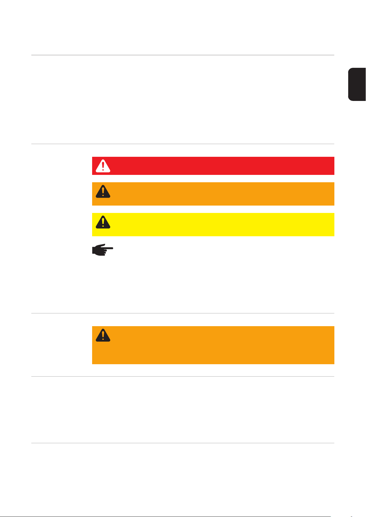
DANGER! Indicates an immediate danger. Death or serious injury may result if
appropriate precautions are not taken.
WARNING! Indicates a possibly dangerous situation. Death or serious injury may
result if appropriate precautions are not taken.
CAUTION! Indicates a situation where damage or injury could occur. Minor injury
or damage to property may result if appropriate precautions are not taken.
NOTE! Indicates the possibility of flawed results and damage to the equipment.
IMPORTANT! Indicates tips for correct operation and other particularly useful information.
It does not indicate a potentially damaging or dangerous situation.
If you see any of the symbols depicted in the "Safety Rules," special care is required.
WARNING! Work performed incorrectly can cause serious injury and damage.
DATCOM components should only be installed and set up in accordance with the
technical specifications. Do not start operation or carry out maintenance work before you have read the ‘Safety instructions’ chapter.
Open the inverter's connection
area
Galvanic isolation
in the inverter
The inverter connection area should only be opened by a licensed electrician.
The connection area should only be opened after being disconnected from the main power
supply.
The power module, which is enclosed in a separate housing, must only be opened by a
trained Fronius service technician and only when in a de-energized state.
Due to their design and function, Fronius inverters offer maximum safety protection during
installation of the DATCOM components. Full galvanic isolation between the DC and AC
side guarantees the greatest possible degree of safety.
The DATCOM components also have full galvanic isolation from the inverter to guarantee
maximum safety during operation.
5
Page 6

Data communication cables should never be laid together with cables that carry mains voltage.
Repairs Repairs to the Fronius inverters and the DATCOM components should only be carried out
by Fronius-trained service personnel.
6
Page 7

General
EN-US
Fronius Solar Net
- Basics
DATCOM / Plug-in
card principle
DATCOM components with external housing
Fronius Solar Net is the basis for unlimited, individual application of DATCOM components. Fronius Solar Net is a data network which enables several Fronius inverters to exchange data with DATCOM components.
The Fronius Solar Net data network operates as a ring-shaped bus system. A single data
link between the individual components enables communication between one or more Fronius inverters and the DATCOM components. This minimizes the cabling effort for the individual DATCOM components.
DATCOM components are available as plug-in cards (similar to the PC). Depending on the
country setup, Fronius inverters can be equipped with up to three plug-in cards within the
housing.
Plug-in cards communicate within the inverter via its internal network. External communication to Fronius Solar Net takes place via Fronius Com Cards.
For increased flexibility, DATCOM components are also available in versions with an external housing (box).
DATCOM components with external housings are designed in accordance with degree of
protection IP 20. For this reason, they are suitable for interior applications only or must be
placed in an appropriately rated weather-proof housing.
If required, the base of an external housing can be clipped onto a commercially-available
DIN rail.
Maximum number
of DATCOM components and inverters
DATCOM components with external housings are equipped with an input „IN“ and output
„OUT“ for data communication within the network.
The following maximum number of DATCOM components and inverters can be connected
to a total system (as of May 2008):
- 100 Fronius inverters (Fronius IG, Fronius IG Plus, Fronius IG Plus V, Fronius IG TL,
Fronius CL or Fronius Agilo - different models can be combined)
- 1 Datalogger pro or easy card / box or Datalogger Web or Fronius Personal Display DL
- 1 Fronius Power Control Card / Box
- 10 sensor cards / boxes
- 10 public display cards / boxes
- 1 interface card / box
- 200 string controls
However, the system is designed to be easily upgradeable as new DATCOM components
are developed.
7
Page 8

Core of Fronius
Solar Net: the Datalogger
The core of Fronius Solar Net is the Datalogger. It coordinates data transmissions and ensures that even large volumes of data are distributed and stored quickly and securely. In
addition, the Datalogger also records data for the entire system over long periods of time.
The following devices have a Datalogging function:
- Fronius Datalogger pro
The Datalogger pro can record data from up to 100 inverters and 10 sensor cards/
boxes.
- Fronius Datalogger easy
The Datalogger easy can only record data from the inverter and sensor card / box using Address 1.
- Fronius Datalogger Web
The Datalogger Web can record data transmitted via the Internet from up to 100 inverters and 10 sensor cards/boxes.
- Fronius Personal Display DL Box
The Fronius Personal Display DL Box can record data from up to 100 inverters and
one sensor card/box.
The Fronius Datalogger easy / pro has
- two data interfaces for direct data transfer to the PC (RS232 and USB)
- one data interface for remote PC data queries via modem and telephone line (RS232)
The Fronius Datalogger Web has a 10/100 MBit Ethernet interface.
Fronius Com
Cards for connecting inverters
to Fronius Solar
Net
IMPORTANT! In the rest of this manual, the Datalogger pro, Datalogger easy and Data-
logger Web are only referred to specifically if the information relates solely to that version.
The term "Datalogger" is used on its own for information that relates to Datalogger pro, Datalogger easy and Datalogger Web.
Fronius Com Cards provide the data link from a Fronius inverter to Fronius Solar Net and
to the DATCOM components connected to it. In addition, Fronius Com Cards also offer galvanic isolation between the photovoltaic ystem and the inverters providing additional safety. Fronius Com Cards must be installed in each inverter connected to Fronius Solar Net.
NOTE! Every Fronius inverter to be monitored using a datalogger requires a
COM Card, even if the system only contains one Fronius inverter. In this case, the
Fronius Com Card serves as a link between the internal network of the inverter
and the Fronius Solar Net interface of the datalogger.
Each Fronius Com Card is equipped with two RS 422 interfaces - an input and an output.
The input is labeled „IN“ and the output is labeled „OUT.“
8
Page 9
General connections and displays
EN-US
General
General connections and displays
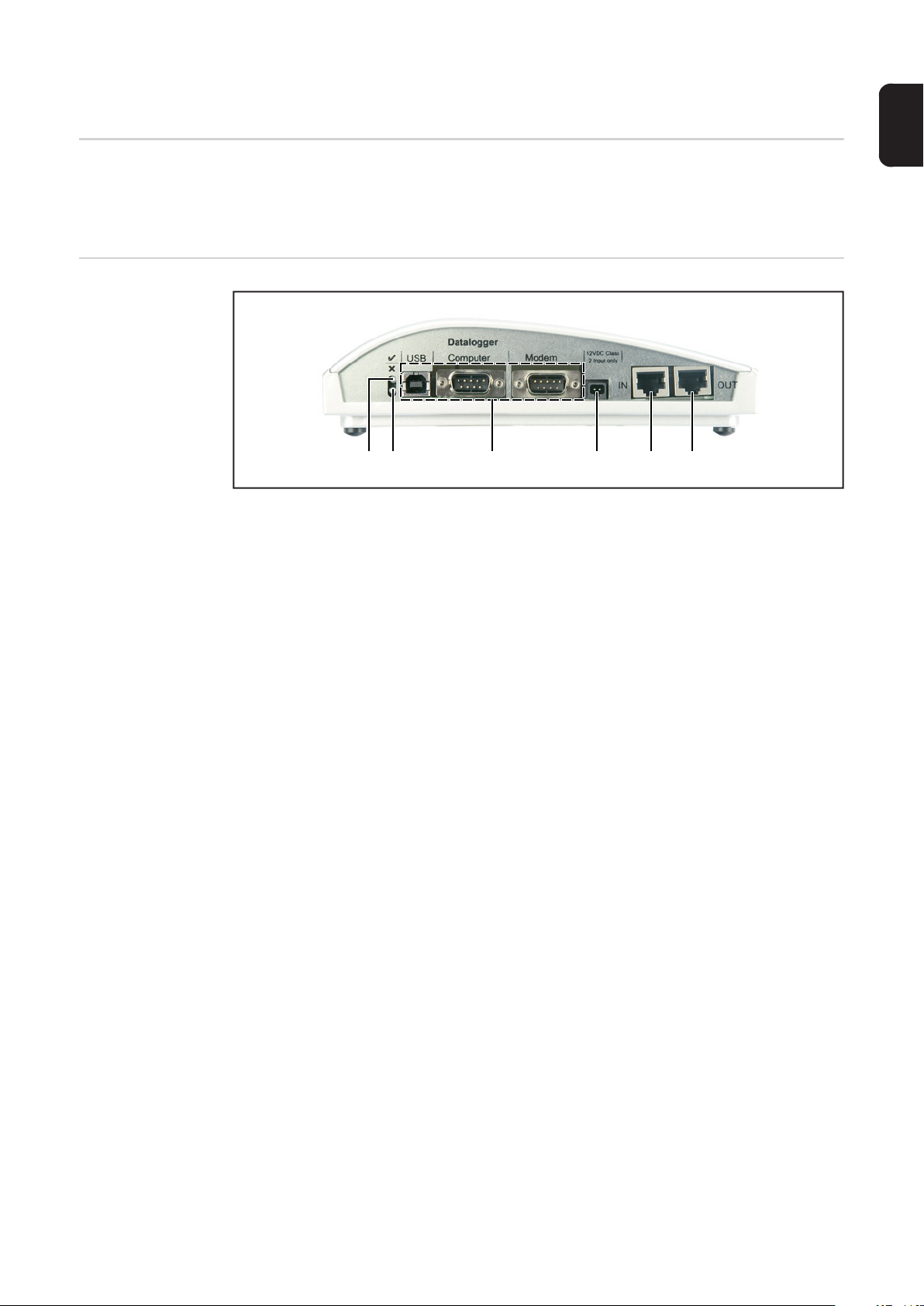
IMPORTANT! The following figure shows the connection area for DATCOM components
using the Datalogger pro box as an example. Area (5) / (6) may differ depending on the
DATCOM components.
(1) (2) (3) (4) (5) (6)
(1) Green status LED ... lights up when there is sufficient power supply to the compo-
nents. When the green LED is not lit, sufficient power supply should be provided
(section "Mains supply").
(2) Red status LED ... lights up continuously when there is sufficient supply, but an
error has occurred in the data communication (e.g., two sensor cards with the
same address).
Also lights up when the termination plug is not inserted correctly.
IMPORTANT! The "red status LED" may turn on briefly during operation. This does
not indicate an error. The "red status LED" is also used for additional functions for
various DATCOM components.
(3) Specific connections ... depending on the functionality of the respective compo-
nent.
(4) Mains supply connection socket ... ...... used to connect the power pack to the
power supply ("Mains supply" section).
(5) Data communication input "IN"
(6) Data communication output "OUT"
9
Page 10

Mains supply to DATCOM components
General Power is supplied to DATCOM components independently of the inverter. This ensures a
power supply when there is no power from the photovoltaic modules. Power is supplied to
DATCOM components via Fronius com cards or plug-in power packs. This is particularly
important when using a Fronius Sensor Card because this ensures that the datalogger will
be able to record all data even at night.
Power supply to
DATCOM components via Fronius
Com Card
Fronius Com Cards are responsible for powering DATCOM components. The integrated
power supply of a Fronius Com Card is implemented via special contacts in the slot, which
continue to supply power even when there is no power from the photovoltaic modules.
Fronius Com Cards version 1.7 and higher are equipped with a switchedmode power supply and can be used with several supply voltages (208 V / 220 V / 230 V / 240 V / 277 V).
WARNING! An electric shock can be fatal. Danger of an electrical shock due to
insufficient dimensioning for US-specific grid voltages. Fronius Com Cards up to
version 1.4B (item number 4,070,769) cannot be used with the Fronius IG Plus
USA.
10
Up to version 1.4B:
Item number 4,070,769
(1) AC fuse
(1)
(1)
Version 1.7 and higher:
Item number 4,070,913
(1) Jumper
Page 11

One Fronius Com Card can supply three additional DATCOM components, or one additional DATCOM component if it is located in a Datalogger Web. Because the power is supplied via the data cable, the DATCOM components in an external housing are also
supplied.
NOTE! When using more than 12 inverters in a system, the power supply can be
deactivated for individual Fronius Com Cards to decrease the power consumption
for the DATCOM.
EN-US
Checking the
power supply via
Fronius Com
Cards
Power pack
Once cabling and installation of system components is complete, including the network
connection to all inverters, the green LED should light up on all Fronius Solar Net clients.
If this is not the case:
- Check cable connections
- Check that all inverters are connected to the network
IMPORTANT! Once the power has been turned on, the Fronius Com Card requires approx. 10 s until the green LED lights up.
If the green LED is not lit for individual system components:
- Plug another power pack into the corresponding DATCOM component
Each DATCOM component with external
housing and the Fronius Com Card is
equipped with a 12 V power pack connection socket.
NOTE! If a system only has one
inverter but more than 3 DATCOM
components, the Fronius Com
Card in the inverter may not provide sufficient power for all DATCOM components. This means
that the green LED would not light
up on all DATCOM components.
In this case, the additional power
pack should be plugged into one
of the DATCOM components with
no green LED.
If there is a Fronius Datalogger Web in Solar Net, the Fronius Com Card can only supply
one additional DATCOM component, e.g., inverter + Fronius Datalogger Web + Fronius
Sensor Box. One power pack can supply up to eight DATCOM components. No additional
supply cables are needed for this. The data communication cable is used to provide power
between components.
11
Page 12

NOTE! The power pack available from Fronius was designed specifically for
DATCOM components. Do not use any other power pack.
IMPORTANT! The scope of delivery for the power pack includes a power adapter for the
following regions:
- Australia
-EU
-UK
- USA
12
Page 13

Cabling
EN-US
Fronius Solar Net
clients
Fronius Solar Net
Client Cabling
Requirements for
the Solar Net Data
Cables
Inverters with Fronius Datamanager, Fronius Hybridmanager or Fronius Com Card, DATCOM components with external housing or other DATCOM components will hereinafter be
referred to as Fronius Solar Net clients.
The data connection for the Fronius Solar Net client is a 1:1 connection using 8-pin data
cables and RJ-45 plugs.
The overall line length in a Fronius Solar Net ring must not exceed 1000 m.
Shielded CAT5 (new) and CAT5e (old) cables compliant with ISO 11801 and EN 50173
must be used for the Fronius Solar Net client cabling. Other cables are not permitted.
IMPORTANT! Do not use ISO/IEC-11801 U/UTP cables!
Permitted cables:
- S/STP
- F/STP
- S/FTP
The shield must be crimped onto a CAT5-compatible shielded plug.
- F/FTP
- SF/FTP
- S/UTP
- F/UTP
- U/FTP
- U/STP
Due to the fact that the wires in Ethernet cables are twisted, you must make sure the twisted pairs of wires are assigned correctly for cabling in accordance with TIA/EIA-568B:
Fronius Solar Net contact Pair no. Color
1 +12 V 3 white/orange line
2 GND 3
3 TX+ IN, RX+ OUT 2 white/green line
4 RX+ IN, TX+ OUT 1
5 RX- IN, TX- OUT 1 white/blue line
6 TX- IN, RX- OUT 2
7 GND 4 white/brown line
8 +12 V 4
Cabling compliant with TIA/EIA-568B
orange/white line
or orange
blue/white line
or blue
green/white line
or green
brown/white line
or brown
- Make sure that the wires are assigned correctly.
- When setting up an independent ground connection (e.g., in patch panels), make sure
that the shield is grounded on one side of the cable only.
13
Page 14

The following structured cabling standards must generally be observed:
- EN 50173-1 for Europe
- ISO/IEC 11801:2002 internationally
- TIA/EIA 568 for North America
Rules for use of copper cables apply.
Preassembled
data cables
Fronius Solar Net
client cabling
The following preassembled data cables are available from Fronius:
- CAT5 cable 1 m ... 43,0004,2435
- CAT5 cable 20 m ... 43,0004,2434
- CAT5 cable 60 m ... 43,0004,2436
The cables listed above are 8-pin, 1:1 LAN network cables, shielded and twisted, including
RJ 45 plugs.
IMPORTANT! Data cables are not UV resistant. They should be protected from sunlight
when laid outdoors.
Two termination plugs are included in the
scope of delivery of the Fronius Datalogger,
and of each DATCOM component that has
a Datalogger function.
Termination plugs
Fronius Solar Net client cabling:
Following the cable connections described below, connect each "OUT" socket of the
1
previous Fronius Solar Net client to the "IN" socket of the next client.
Connect a termination plug at the "IN" input of the first Solar Net client
2
Connect a termination plug at the "OUT" output of the last Solar Net client
3
IMPORTANT! When using the termination plugs, the total individual lengths of all connection cables must not exceed 1000 m.
NOTE! All "IN" inputs and "OUT" outputs of Fronius Solar Net clients must be
filled either with cable connections or termination plugs.
1
IN
OUT
(1) (1)
IN
2
OUT
...
...
...
...
IN
n
OUT
14
Page 15
(1) Termination plugs
Cabling with termination plugs
Cabling without termination plugs
EN-US
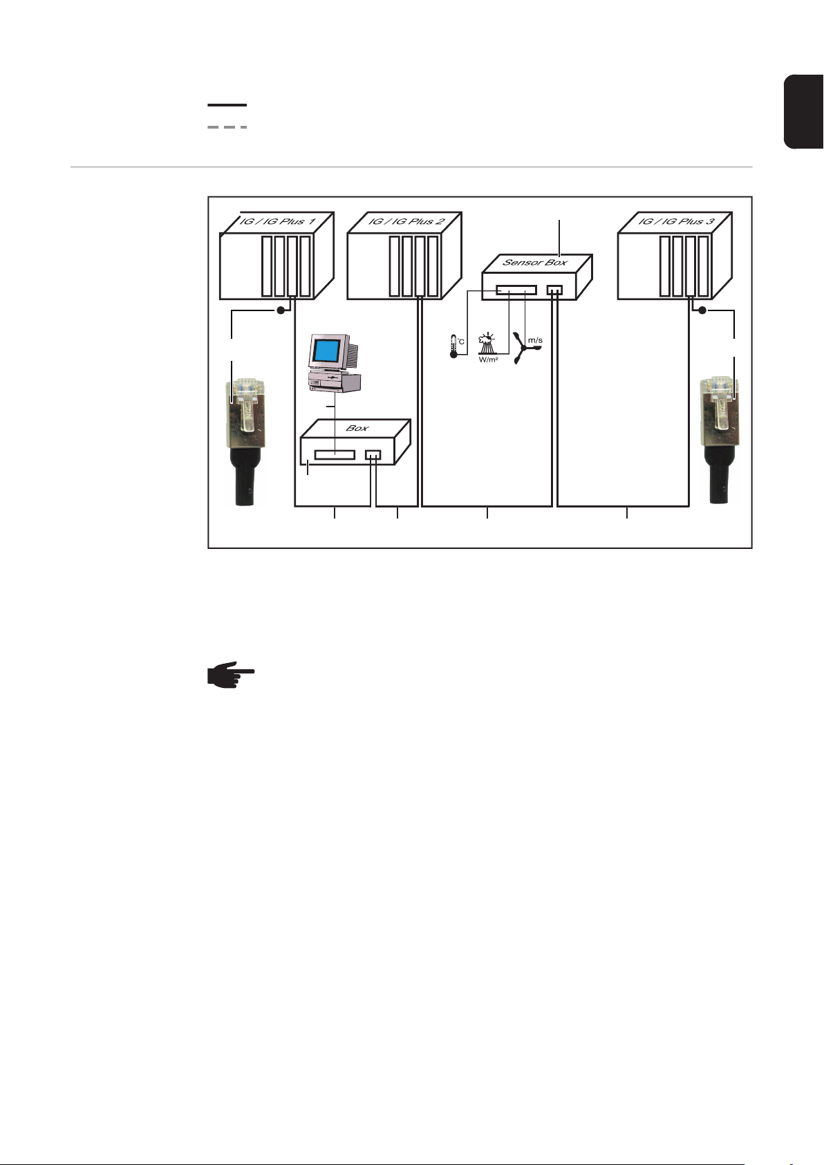
Example of system component
networking in
Fronius Solar Net
IN OUT
IN OUT
(1)
PC
PC RS-232
(3)
(1) Termination plugs
(2) Data cable
(3) Datalogger
(4) Sensor box in external housing
(2)
IN OUT
(2) (2) (2)
(4)
IN OUT
IN OUT
(1)
NOTE! Potential differences can lead to malfunctions or in the worst case to the
destruction of DATCOM components. DATCOM components must not be networked with one another across buildings. Photovoltaic systems with inverters
and DATCOM components in different buildings require DATCOM systems that
are installed separately.
15
Page 16

Installing plug-in cards into inverters
General Please see the operating instructions for the respective inverter for information regarding
plug-in card installation.
Please note the safety and warning information in your inverter’s operating instructions.
Safety
WARNING! An electric shock can be fatal. Danger from grid voltage and DC volt-
age from solar modules.
- The connection area should only be opened by a licensed electrician.
- The separate power stage set area should only be disconnected from the
connection area after first being disconnected from the grid power.
- The separate power stage set area should only be opened by Fronius-trained
service personnel.
Before making any connections, make sure that the AC and DC sides are disconnected from the inverter, e.g.:
- Switch off the AC automatic circuit breaker for the inverter
- Cover solar modules
Please observe the 5 safety rules.
WARNING! An electric shock can be fatal. Danger from residual voltage from capacitors.
You must wait until the capacitors have discharged.
NOTE! Follow general ESD precautions when handling plug-in cards.
16
Page 17
Defining system components in Fronius Solar Net
General Fronius Solar Net will recognize different DATCOM components automatically (datalogger,
sensor card, etc.). However, there is no automatic distinction between several identical
DATCOM components. For this reason, each system component must have an individual
number (address) to uniquely identify each system component in Fronius Solar Net (inverter or DATCOM component).
Fronius inverters give you the option to set the address directly on the display. However,
some versions of Fronius IG are not equipped with a display. In this case, the address can
be set via two keys.
DATCOM components are equipped with a special setting wheel for addresses. A small
screwdriver is required for this.
EN-US
Setting the address on the inverter
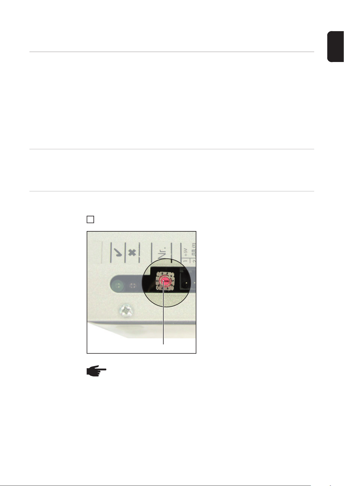
Setting the address on DATCOM components
Please see the inverter operating instructions for setting the inverter address.
Proceed as follows for all DATCOM components (whether card or box):
Turn the setting wheel (1) to the desired address using a screwdriver
1
IMPORTANT! You do not have to set the
address for the datalogger because there is
always only one datalogger per system.
(1)
NOTE! Two identical devices should never have the same address in a network.
Example:
- Permitted:
Fronius IG „Adress 1“, Sensor Card „Adress 1“
- Not permitted:
Fronius IG 20 „Adress 1“, Fronius IG 30 „Adress 1“
17
Page 18

Technical Data
Datalogger Card /
Box
Datalogger Card / Box
Memory capacity 540 kByte
Memory duration approx. 1000 days
(1 Fronius IG or Fronius IG Plus, memory cycle 30 minutes)
Supply voltage 12 V DC
Power consumption 0,4 W
- With wireless transceiver box: max. 0,6 W
Box degree of protection IP 20
Dimensions (l x w x h)
- Datalogger Card: 140 x 100 x 26 mm
- Datalogger Box: 190 x 115 x 53 mm
Datalogger Card interfaces Socket: Description:
- USB: USB „USB“
- RS 232: 9-pin submin „PC“
- RS 232: 9-pin submin „Modem“
Datalogger Box interfaces
- USB: USB „USB“
- RS 232: 9-pin submin „PC“
- RS 232: 9-pin submin „Modem“
- RS 422: RJ 45 „IN“
- RS 422: RJ 45 „OUT“
Datalogger & Interface
Datalogger & Interface (Box)
Memory capacity 540 kByte
Memory duration approx. 1000 days
(1 Fronius IG or Fronius IG Plus, memory cycle 30 minutes)
Supply voltage 12 V DC
Power consumption 2.8 W
Box degree of protection IP 20
Dimensions (l x w x h) 210 x 110 x 72 mm
Interfaces Socket: Description:
- USB: USB „USB“
- RS 232: 9-pin submin „PC“
- RS 232: 9-pin submin „Modem“
- RS 232: 9-pin submin „Data“
- RS 422: RJ 45 „IN“
- RS 422: RJ 45 „OUT“
18
Page 19

Sensor Card / Box
Sensor Card / Box
Supply voltage 12 V DC
Power consumption
- Sensor card:
- Sensor box:
Box degree of protection IP 20
Dimensions (l x w x h)
- Sensor card:
- Sensor box:
Interfaces
(only sensor box)
- RS 422: RJ 45 „IN“
- RS 422: RJ 45 „OUT“
Channels T1, T2
- Sensors: PT1000
- Measuring range: -25°C...75°C; -13°F...167°F
- Accuracy: 0,5°C; 0,8°F
- Resolution: 1 °C; 1 °F
Irradiance channel
- Measuring range: 0...100 mV
- Accuracy: 3 %
Channels D1, D2
- Max. voltage level 5.5 V
- Max. frequency 2500 Hz
- Min. pulse duration 250 us
- Switching threshold „OFF“ („LOW“): 0...0.5 V
- Switching threshold „ON“ („HIGH“): 3...5.5 V
Current input channel
- Measuring range: 0...20 mA
- Accuracy: 5%
Socket: Description:
1.1 W
1.3 W
140 x 100 x 26 mm
197 x 110 x 57 mm
0...200 mV
0...1 V
4...20 mA
EN-US
Com Card
Com card up to version 1.4B (4,070,769)
Supply voltage 230 V (+10% / -15%)
Dimensions (l x w x h)
- Plug-in card only: 140 x 100 x 33 mm
Interfaces Socket: Description:
- RS 422: RJ 45 „IN“
- RS 422: RJ 45 „OUT“
19
Page 20

Com card version 1.7 and higher (4,070,913)
Supply voltage 208 V / 220 V / 230 V / 240 V / 277 V (+10% / -15%)
Dimensions (l x w x h)
- Plug-in card only: 140 x 100 x 28 mm
Interfaces Socket: Description:
- RS 422: RJ 45 „IN“
- RS 422: RJ 45 „OUT“
Public Display
Card / Box
Interface Card /
Box
Public Display Card / Box
Supply voltage 12 V DC
Power consumption
- Public display card: 1.2 W
- Public display box: 1.6 W
Box degree of protection IP 20
Dimensions (l x w x h)
- Public display card: 140 x 100 x 26 mm
- Public display box: 197 x 110 x 57 mm
Interfaces Socket: Description:
- RS 232 9-pin submin „Display“
- Public display Box additional:
RS 422: RJ 45 „IN“
RS 422: RJ 45 „OUT“
Interface Card / Box
Supply voltage 12 V DC
Power consumption
- Interface card: 1.2 W
- Interface box: 1.6 W
Box degree of protection IP 20
Interface box ambient conditions 0°C - +50°C
+32°F - +122°F
Dimensions (l x w x h)
- Interface card: 140 x 100 x 26 mm
- Interface box: 197 x 110 x 57 mm
Interfaces Socket: Description:
- RS 232 9-pin submin „Data“
- Interface box additional:
RS 422 RJ 45 „IN“
RS 422 RJ 45 „OUT“
The baud rate can be set via the „Baud“ adjuster:
- 2400, 4800, 9600, 14400, 19200
20
Page 21

Fronius Manufacturer's Warranty
EN-US
Fronius Manufacturer's Warranty
Detailed warranty terms and conditions specific to your country can be found online:
www.fronius.com/solar/warranty
To take advantage of the full warranty duration for your newly installed Fronius inverter or
accumulator, register your product at: www.solarweb.com.
21
Page 22

22
Page 23

Tabla de contenido
Seguridad................................................................................................................................................... 25
Generalidades....................................................................................................................................... 25
Explicación de las indicaciones de seguridad....................................................................................... 25
Seguridad.............................................................................................................................................. 25
Abrir la zona de conexión del inversor.................................................................................................. 25
Separación galvánica en el inversor..................................................................................................... 25
Reparaciones........................................................................................................................................ 26
Generalidades............................................................................................................................................ 27
La Fronius Solar Net - Principios .......................................................................................................... 27
DATCOM / Principio de tarjeta enchufable........................................................................................... 27
Componentes DATCOM con caja externa............................................................................................ 27
Número máximo de componentes DATCOM e inversores................................................................... 27
La pieza central de Fronius Solar Net: el Datalogger ........................................................................... 28
Fronius Com Cards para la conexión de un inversor a Fronius Solar Net............................................ 28
Conexiones e indicaciones generales ....................................................................................................... 29
Generalidades....................................................................................................................................... 29
Conexiones e indicaciones generales .................................................................................................. 29
Alimentación de corriente de los componentes DATCOM......................................................................... 30
Generalidades....................................................................................................................................... 30
Alimentación de corriente de los componentes DATCOM mediante Fronius Com Card .................... 30
Comprobar la alimentación de corriente mediante Fronius Com Card ................................................ 31
Equipo de alimentación......................................................................................................................... 32
Cableado.................................................................................................................................................... 33
Participantes de Fronius Solar Net ....................................................................................................... 33
Cableado de los participantes de Fronius Solar Net............................................................................. 33
Condiciones para los cables de datos de Fronius Solar Net ................................................................ 33
Cables de datos preconfeccionados..................................................................................................... 34
Cablear los participantes de Fronius Solar Net .................................................................................... 34
Ejemplo para la conexión en red de los componentes del sistema en Fronius Solar Net.................... 35
Introducir las tarjetas enchufables en el inversor....................................................................................... 36
Generalidades....................................................................................................................................... 36
Seguridad.............................................................................................................................................. 36
Definir los componentes del sistema en la Fronius Solar Net ................................................................... 37
Generalidades....................................................................................................................................... 37
Ajustar la dirección en el inversor......................................................................................................... 37
Ajustar la dirección de los componentes DATCOM.............................................................................. 37
Datos técnicos ........................................................................................................................................... 38
Datalogger Card / Box .......................................................................................................................... 38
Datalogger & Interface.......................................................................................................................... 38
Sensor Card / Box................................................................................................................................. 39
Com Card.............................................................................................................................................. 39
Public Display Card / Box ..................................................................................................................... 40
Interface Card / Box.............................................................................................................................. 40
Garantía de fábrica de Fronius .................................................................................................................. 41
Garantía de fábrica de Fronius ............................................................................................................. 41
ES
23
Page 24

24
Page 25
Seguridad
Generalidades El presente manual de instrucciones pretende familiarizarle con la instalación, el manejo,
el cuidado y el mantenimiento de los componentes DATCOM para el inversor de Fronius.
Por su propio interés, le recomendamos lea detenidamente el manual de instrucciones y
siga atentamente las instrucciones que figuran en el mismo. De este modo, evitará averías
originadas por fallos de manejo. El equipo estará en disposición continua para el uso y
ofrecerá una larga vida útil.
Los componentes DATCOM se describen detalladamente en el CD ROM suministrado
junto con el Datalogger, así como en Internet en "www.fronius.com".
ES
Explicación de
las indicaciones
de seguridad
Seguridad
¡PELIGRO! Indica un peligro inminente. Si no se evita este peligro, las conse-
cuencias son la muerte o lesiones de carácter muy grave.
¡ADVERTENCIA! Indica una situación posiblemente peligrosa. Si no se evita
esta situación, las consecuencias pueden ser la muerte y lesiones de carácter
muy grave.
¡PRECAUCIÓN! Indica una situación posiblemente perjudicial. Si no se evita
esta situación, se pueden producir lesiones de carácter leve o insignificantes, así
como daños materiales.
¡OBSERVACIÓN! Indica la posibilidad de obtener unos resultados mermados de
trabajo y que se puedan producir daños en el equipamiento.
¡IMPORTANTE! Indica consejos de aplicación y otra información especialmente útil. No
se trata de una palabra señaladora que indica una situación perjudicial o peligrosa.
Cuando vea uno de los símbolos representados en el capítulo "Indicaciones de seguridad", se requiere un mayor grado de atención.
¡ADVERTENCIA! Los trabajos realizados de forma defectuosa pueden causar
graves daños personales y materiales. La Instalación y la puesta en servicio de
los componentes DATCOM solo se debe realizar en el marco de las disposiciones técnicas. Antes de la puesta en servicio y la realización de trabajos de cuidado resulta imprescindible leer el capítulo "Indicaciones de seguridad".
Abrir la zona de
conexión del inversor
Separación galvánica en el inversor
Solo instaladores oficiales deben abrir la zona de conexión del inversor.
Abrir la zona de conexión solo cuando no hay tensión en la misma.
Solo personal de servicio formado por Fronius debe abrir la zona encapsulada de la etapa
de potencia cuando no hay tensión en la misma.
Gracias a su construcción y funcionamiento, los inversores de Fronius ofrecen máxima seguridad durante la instalación de los componentes DATCOM. La separación galvánica
completa entre el lado de corriente continua y alterna garantiza una seguridad absoluta.
25
Page 26

Asimismo, a fin de garantizar una seguridad máxima durante el servicio, los componentes
DATCOM del inversor también están separados por completo galvánicamente.
¡Jamás se deben instalar los cables para la comunicación de datos conjuntamente con las
líneas que se encuentran bajo tensión de red!
Reparaciones Solo personal de servicio formado por Fronius debe realizar reparaciones en los inverso-
res de Fronius y en los componentes DATCOM.
26
Page 27

Generalidades
La Fronius Solar
Net - Principios
DATCOM / Principio de tarjeta enchufable
Componentes
DATCOM con
caja externa
La Fronius Solar Net sirve de base para la aplicación individual ilimitada de los componentes DATCOM. Fronius Solar Net es una red de datos que permite el intercambio de datos
entre varios inversores de Fronius y los componentes DATCOM.
La red de datos de Fronius Solar Net corresponde a un sistema de bus en anillo. Una única
conexión de datos entre los diferentes componentes es suficiente en cada caso para la
comunicación de uno o varios inversores de Fronius con los componentes DATCOM. De
este modo se reducen al mínimo las necesidades de cableado de los diferentes componentes DATCOM.
Los componentes DATCOM se ofrecen en forma de tarjetas enchufables (similares a las
del PC). Según la configuración de país, los inversores de Fronius están preparados para
la colocación de una a tres tarjetas enchufables dentro de la caja.
Las tarjetas enchufables se comunican dentro del inversor a través de su red interna. La
comunicación externa a Fronius Solar Net se realiza a través de Fronius Com Cards.
Para aumentar la flexibilidad, los componentes DATCOM también se encuentran disponibles como versiones con caja externa (box).
Los componentes DATCOM con caja externa están realizados según el tipo de protección
IP 20. Por lo tanto, resultan adecuados exclusivamente para aplicaciones interiores o deben ser instalados en cajas aptas para exteriores. Si fuera necesario, se puede engatillar
el fondo de una caja externa sobre un riel de sombrerete comercial.
ES
Número máximo
de componentes
DATCOM e inversores
Los componentes DATCOM con caja externa disponen de una entrada „IN“ y de una salida „OUT“ para la comunicación de datos en la red.
La siguiente cantidad máxima de componentes DATCOM e inversores puede ser agrupada para componer un sistema total (versión: mayo 2008):
- 100 inversores de Fronius (Fronius IG, Fronius IG Plus, Fronius IG Plus V, Fronius IGTL, Fronius CL o Fronius Agilo: se pueden combinar diferentes tipos)
- 1 Datalogger pro o easy Card / Box o Datalogger Web o Fronius Personal Display DL
- 1 Fronius Power Control Card / Box
- 10 Sensor Cards / Boxes
- 10 Public Display Cards / Boxes
- 1 Interface Card / Box
- 200 String Controls
No obstante, el sistema ha sido construido de tal modo que se puede equipar fácilmente
con componentes DATCOM que se desarrollen en el futuro.
27
Page 28

La pieza central
de Fronius Solar
Net: el Datalogger
La pieza central de Fronius Solar Net es el Datalogger. Este elemento se encarga de coordinar el tráfico de datos y garantiza también que se distribuyan de forma rápida y segura
incluso grandes volúmenes de datos. El Datalogger guarda adicionalmente los datos de
toda la instalación durante largos períodos de tiempo.
Los siguientes equipos con función de Datalogging están disponibles:
- Fronius Datalogger pro
El Datalogger pro guarda los datos de hasta 100 inversores y 10 Sensor Cards /
Boxes.
- Fronius Datalogger easy
El Datalogger easy solo guarda los datos del inversor y de la Sensor Card / Box con
la dirección 1.
- Fronius Datalogger Web
El Datalogger Web guarda los datos de hasta 100 inversores y 10 Sensor Cards /
Boxes que se transmiten a través de Internet.
- Fronius Personal Display DL Box
La Fronius Personal Display DL Box guarda los datos de hasta 100 inversores y de
una Sensor Card / Box.
El Fronius Datalogger easy / pro dispone de:
- Dos interfaces de datos para la transmisión de datos directa al PC (RS232 y USB)
- Un interfaz de datos para la consulta a distancia de datos a través de un PC remoto
a través de módem y línea de teléfono (RS232)
El Fronius Datalogger Web dispone de una interfaz de Ethernet de 10/100 MBits.
Fronius Com
Cards para la conexión de un inversor a Fronius
Solar Net
¡IMPORTANTE! A continuación solo se hace referencia específica al Datalogger pro o al
Datalogger easy, así como al Datalogger Web cuando se trata de una de las tres versiones
en concreto. Para afirmaciones en relación con el Datalogger pro, el Datalogger easy y el
Datalogger Web, se utilizará solo el término "Datalogger".
Las Fronius Com Cards permiten la conexión de datos de un inversor de Fronius a Fronius
Solar Net y los componentes DATCOM conectados a ésta. Las Fronius Com Cards proporcionan además la separación galvánica entre el sistema fotovoltaico y los inversores,
con lo que representan un factor de seguridad esencial. Las Fronius Com Cards se deben
encontrar en cada inversor conectado a Fronius Solar Net.
¡OBSERVACIÓN! También se requiere una Fronius Com Card si se trata de captar los datos de un sólo inversor de Fronius mediante el Datalogger. En este caso,
la Fronius Com Card sirve como acoplador entre la red interna del inversor y el
interfaz de Fronius Solar Net del Datalogger.
Cada Fronius Com Card dispone de dos interfaces RS-422 como entrada y salida. La entrada está designada como „IN“, la salida en cada caso como „OUT“.
28
Page 29

Conexiones e indicaciones generales
Generalidades
Conexiones e indicaciones generales
¡IMPORTANTE! La siguiente ilustración muestra la zona de conexión de los componentes
DATCOM mediante el ejemplo de la Datalogger pro Box. La zona (5) / (6) de los diferentes
componentes DATCOM varía en cada caso.
(1) (2) (3) (4) (5) (6)
(1) LED de estado verde ... Está iluminado si el componente recibe suficiente alimen-
tación de corriente. Si el LED verde no está iluminado, se debe establecer una alimentación de corriente suficiente (apartado "Alimentación de corriente").
(2) LED de estado rojo ... Está iluminado de forma permanente si la alimentación es
suficiente, pero se ha producido un fallo en la comunicación de datos (por ejemplo,
dos Sensor Cards con la misma dirección).
ES
Este LED también está iluminado si las clavijas finales no están enchufadas correctamente.
¡IMPORTANTE! Si el "LED de estado rojo" se ilumina brevemente durante el servicio, esta circunstancia no indica fallo. En varios componentes DATCOM, el "LED
de estado rojo" dispone además de funciones adicionales.
(3) Conexiones específicas... Según la funcionalidad del componente en cuestión.
(4) Zócalo de conexión para alimentación de corriente ... Para conectar un equipo
para la alimentación de corriente (apartado "Alimentación de corriente").
(5) Entrada de comunicación de datos "IN"
(6) Salida de comunicación de datos "OUT"
29
Page 30

Alimentación de corriente de los componentes DATCOM
Generalidades La alimentación de los componentes DATCOM se realiza independientemente del inver-
sor. De este modo, la alimentación de corriente queda asegurada incluso cuando no se
produce el servicio de alimentación de la red. La alimentación de los componentes DATCOM se realiza a través de las Fronius Com Cards o los equipos de alimentación de clavija. En particular, de este modo y en caso de utilización de una Fronius Sensor Card
queda asegurado que el Datalogger vaya guardando todos los datos también por la noche.
Alimentación de
corriente de los
componentes
DATCOM mediante Fronius Com
Card
Las Fronius Com Cards se encargan de la alimentación de los componentes DATCOM.
La fuente de alimentación integrada de una Fronius Com Card es alimentada a través de
unos contactos especiales que también llevan tensión de red cuando no se produce el servicio de alimentación de la red.
Las Fronius Com Cards a partir de la versión 1.7 están equipadas con una fuente de alimentación conmutable por lo que resultan apropiadas para diferentes alimentaciones de
tensión (208 V / 220 V / 230 V / 240 V / 277 V).
¡ADVERTENCIA! Una descarga eléctrica puede ser mortal. Riesgo de una descarga eléctrica debido a un dimensionamiento inapropiado para las tensiones de
red específicas de EE.UU. Para las Fronius Com Cards hasta la versión 1.4B con
el número de artículo 4,070,769, no se admite el servicio con el Fronius IG Plus
EE.UU.
(1) Fusible AC
30
(1)
Hasta versión 1.4B:
Número de artículo 4,070,769
Page 31

A partir de la versión 1.7:
Número de artículo 4,070,913
(1) Saltador
ES
(1)
Comprobar la alimentación de corriente mediante
Fronius Com
Card
Una Fronius Com Card puede alimentar a otros tres componentes DATCOM u otro componente DATCOM cuando hay un Datalogger Web entre ellos. Como la alimentación de
corriente se realiza a través del cable de datos, de este modo también se están alimentando los componentes DATCOM en una caja externa.
¡OBSERVACIÓN! En caso de instalaciones con más de doce inversores, se puede desactivar la alimentación de corriente de algunas Fronius Com Cards para
bajar el consumo de corriente de DATCOM.
En todos los participantes de Fronius Solar Net se debe iluminar el LED verde después de
haber realizado el cableado y la instalación de los componentes del sistema, así como el
establecimiento de la conexión de red de todos los inversores. Si no fuera así:
- Comprobar las uniones por cables
- Comprobar si todos los inversores están conectados a la red
¡IMPORTANTE! Después de encender la tensión de red, la Fronius Com Card necesita
aproximadamente 10 s hasta que se ilumine el LED verde.
Si el LED verde no se ilumina en alguna de las ampliaciones del sistema:
- Conectar un equipo de alimentación de clavija al componente DATCOM correspondiente
31
Page 32

Equipo de alimentación
Todos los componentes DATCOM con caja
externa, así como la Fronius Com Card disponen de un zócalo de conexión de 12 V
para un equipo de alimentación.
¡OBSERVACIÓN! Si una instalación dispone de solo un inversor,
pero de más de 3 componentes
DATCOM, la Fronius Com Card
en el inversor no es capaz de suministrar suficiente energía para
todos los componentes DATCOM.
Eso quiere decir que el LED verde
no se enciende en todos los componentes DATCOM. En este caso, el equipo de alimentación
adicional se debe conectar a uno
de los componentes DATCOM en
los que no se enciende el LED
verde.
Si hay un Fronius Datalogger Web en Solar Net, la Fronius Com Card solo puede alimentar
a otro componente DATCOM más, por ejemplo, inversor + Fronius Datalogger Web + Fronius Sensor Box. Un equipo de alimentación puede alimentar hasta a ocho componentes
DATCOM. En este sentido, no se requieren cables de alimentación adicionales. La distribución de la corriente entre los componentes se realiza a través del cable de conexión
para la comunicación de datos.
¡OBSERVACIÓN! Solo el equipo de alimentación disponible a través de Fronius
es capaz de garantizar la alimentación de los componentes DATCOM. Por lo tanto, jamás se debe conectar un equipo de alimentación diferente.
¡IMPORTANTE! El volumen de suministro del equipo de alimentación incluye adaptadores de red para las siguientes regiones:
- Australia
-EU
-UK
- EE. UU.
32
Page 33

Cableado
Participantes de
Fronius Solar Net
Cableado de los
participantes de
Fronius Solar Net
Condiciones para
los cables de datos de Fronius
Solar Net
Los inversores con Fronius Datamanager, Fronius Hybridmanager o Fronius Com Card,
los componentes DATCOM con caja externa u otros componentes DATCOM se denominan en lo sucesivo participantes de Fronius Solar Net.
La conexión de datos de los participantes de Fronius Solar Net se realiza a través de una
conexión de 1:1 con cables de datos de ocho polos y conectores RJ-45.
La máxima longitud de línea total en un circuito de Fronius Solar Net debe ser de 1000 m.
Para el cableado de los participantes de Fronius Solar Net deben utilizarse exclusivamente cables blindados CAT5 (nuevo) y CAT5e (antiguo) según ISO 11801 y EN50173.
¡IMPORTANTE! ¡No se deben utilizar cables U/UTP según ISO/IEC-11801!
Cables admisibles:
- S/STP
- F/STP
- S/FTP
Por ello debe engarzarse la pantalla protectora para un conector blindado homologado
para CAT5.
- F/FTP
- SF/FTP
- S/UTP
- F/UTP
- U/FTP
- U/STP
ES
Como los conductores en los cables de Ethernet también están torcidos, procurar que los
pares de conductores estén asignados correctamente según el cableado siguiendo TIA/
EIA-568B:
Contacto Fronius Solar Net N.º par Color
1 +12 V 3 blanco / raya naranja
2 GND 3
3 TX+ IN, RX+ OUT 2 blanco / raya verde
4 RX+ IN, TX+ OUT 1
5 RX- IN, TX- OUT 1 blanco / raya azul
6 TX- IN, RX- OUT 2
7 GND 4 blanco / raya marrón
8 +12 V 4
Cableado según TIA/EIA-568B
naranja / raya blanca
o naranja
azul / raya blanca
o azul
verde / raya blanca
o verde
marrón / raya blanca
o marrón
- Tener en cuenta la correcta ocupación de los conductores.
- En caso de una conexión a tierra independiente (por ejemplo, en paneles patch),
prestar atención a que la pantalla protectora solamente esté conectada a tierra en un
lado del cable.
33
Page 34

Por lo general deben cumplirse las siguientes normas para un cableado estructurado:
- Para Europa: EN50173-1
- A nivel internacional: ISO/IEC 11801:2002.
- Para Norteamérica: TIA/EIA 568
Son aplicables las reglas para el uso de cables de cobre.
Cables de datos
preconfeccionados
Cablear los participantes de Fronius Solar Net
Fronius dispone de los siguientes cables de datos preconfeccionados:
- Cable CAT5 de 1 m ... 43,0004,2435
- Cable CAT5 de 20 m ... 43,0004,2434
- Cable CAT5 de 60 m ... 43,0004,2436
Se trata de cables de red LAN de 1:1 de 8 polos, blindados y torcidos, incluyendo las clavijas RJ45.
¡IMPORTANTE! Los cables de datos no son resistentes a la luz ultravioleta. En caso de
instalar los cables de datos en el exterior, deben ser protegidos frente a la radiación solar.
El volumen de suministro del Fronius Datalogger, así como cualquier componente
DATCOM con función de Datalogger incluye dos clavijas finales.
Clavija final
Cablear los participantes de Fronius Solar Net:
Con las uniones por cables descritas se debe conectar en cada caso el zócalo "OUT"
1
del anterior participante de Fronius Solar Net con el zócalo "IN" del siguiente participante.
Conectar una clavija final a la entrada "IN" del primer participante de SolarNet.
2
Conectar una clavija final a la salida "OUT" del último participante de SolarNet.
3
¡IMPORTANTE! En caso utilizar clavijas finales, la suma de las longitudes individuales de
todos los cables de conexión no debe exceder de 1000 m.
¡OBSERVACIÓN! Todas las entradas "IN" y todas las salidas "OUT" de los participantes de Fronius Solar Net deben estar ocupadas con uniones por cables o
clavijas finales.
34
Page 35

IN
1
OUT
IN
2
OUT
...
IN
n
OUT
Ejemplo para la
conexión en red
de los componentes del sistema en
Fronius Solar Net
(1) (1)
(1) Clavija final
Cableado con clavija final
Cableado sin clavija final
IN OUT
(1)
PC RS-232
PC
IN OUT
...
...
...
(4)
IN OUT
ES
IN OUT
(1)
(3)
(1) Clavija final
(2) Cable de datos
(3) Datalogger
(4) Sensor Box en caja externa
¡OBSERVACIÓN! Las diferencias de potencial pueden provocar funciones erróneas o, en el peor de los casos, la destrucción de los componentes DATCOM.
Los componentes DATCOM no deben estar en red entre sí entre varios edificios.
Las instalaciones fotovoltaicas con inversores y componentes DATCOM en diferentes edificios requieren unos sistemas DATCOM con instalaciones separadas.
(2)
IN
OUT
(2) (2) (2)
35
Page 36

Introducir las tarjetas enchufables en el inversor
Generalidades Por lo general, la introducción de las tarjetas enchufables en el inversor debe realizarse
según el manual de instrucciones del correspondiente inversor.
Se deben tener en cuenta las indicaciones de seguridad y las advertencias en los manuales de instrucciones de los inversores.
Seguridad
¡ADVERTENCIA! Una descarga eléctrica puede ser mortal. Peligro originado por
la tensión de red y la tensión DC de los módulos solares.
- Sólo instaladores eléctricos oficiales pueden abrir la zona de conexión.
- La zona separada de las partes de potencia sólo se puede separar de la
zona de conexión cuando se encuentra en el estado sin tensión.
- Sólo el personal de servicio formado por Fronius puede abrir la zona separada de las partes de potencia.
Antes de realizar cualquier tipo de trabajo de conexión se debe procurar que el
lado de AC y DC delante del inversor esté sin tensión, por ejemplo:
- Conmutar el autómata de seguridad AC para el inversor sin tensión
- Cubrir los módulos solares
Tener en cuenta las 5 reglas de seguridad.
¡ADVERTENCIA! Una descarga eléctrica puede ser mortal.
Peligro originado por la tensión residual de los condensadores. Esperar el tiempo
de descarga de los condensadores.
¡OBSERVACIÓN! Para el manejo de tarjetas enchufables se deben tener en
cuenta las disposiciones ESD generales.
36
Page 37

Definir los componentes del sistema en la Fronius
Solar Net
Generalidades Fronius Solar Net detecta automáticamente los diferentes componentes DATCOM (Data-
logger, Sensor Card, etc.). No obstante, no se realiza ninguna diferenciación automática
entre varios componentes DATCOM idénticos. Cada componente del sistema debe tener
un número individual (= dirección) para poder definir cada componente del sistema (inversor o componente DATCOM) de manera unívoca en Fronius Solar Net.
Los inversores de Fronius permiten efectuar el ajuste de la dirección directamente en la
pantalla. Algunas versiones del Fronius IG no disponen de pantalla. En este caso, se realiza el ajuste de la dirección por medio de dos teclas.
Los demás componentes DATCOM disponen de una rueda de ajuste especial para direccionar. A tal fin se requiere un pequeño destornillador para tornillos de cabeza ranurada.
Ajustar la dirección en el inversor
Ajustar la dirección de los componentes
DATCOM
El ajuste de la dirección en el inversor figura en el manual de instrucciones del inversor.
Para todos los componentes DATCOM se debe proceder como sigue, independientemente de si se trata de una Card o una Box:
Mediante un destornillador para tornil-
1
los de cabeza ranurada adecuado se
debe girar la rueda de ajuste (1) a la dirección deseada
ES
¡IMPORTANTE! Como en una instalación
no puede haber más de un Datalogger, no
se requiere ningún ajuste de la dirección en
el Datalogger.
(1)
¡OBSERVACIÓN! Dos aparatos en una misma red jamás pueden tener la misma
dirección.
Ejemplo:
- Admisible:
Fronius IG „Dirección 1“, Sensor Card „Dirección 1“
- Inadmisible:
Fronius IG 20 „Dirección 1“, Fronius IG 30 „Dirección 1“
37
Page 38

Datos técnicos
Datalogger Card /
Box
Datalogger Card / Box
Capacidad de memoria 540 kBytes
Tiempo de memorización aproximadamente aprox. 1000 días
(1 Fronius IG o Fronius IG Plus, ciclo de memorización 30 minutos)
Alimentación de tensión 12 V DC
Consumo de energía 0,4 W
- con Wireless Transceiver Box: máx. 0,6 W
Tipo de protección Box IP 20
Dimensiones (longitud x anchura x altura)
- Datalogger Card: 140 x 100 x 26 mm
- Datalogger Box: 190 x 115 x 53 mm
Interfaces Datalogger Card Zócalo: Designación:
- USB: USB „USB“
- RS 232: Sub-D de nueve polos „PC“
- RS 232: Sub-D de nueve polos „Modem“
Interfaces Datalogger Box
- USB: USB „USB“
- RS 232: Sub-D de nueve polos „PC“
- RS 232: Sub-D de nueve polos „Modem“
- RS 422: RJ 45 „IN“
- RS 422: RJ 45 „OUT“
Datalogger & Interface
Datalogger & Interface (Box)
Capacidad de memoria 540 kBytes
Tiempo de memorización aprox. 1000 días
(1 Fronius IG o Fronius IG Plus, ciclo de memorización 30 minutos)
Alimentación de tensión 12 V DC
Consumo de energía 2.8 W
Tipo de protección Box IP 20
Dimensiones (longitud x anchura x altura) 210 x 110 x 72 mm
Interfaces Zócalo: Designación:
- USB: USB „USB“
- RS 232: Sub-D de nueve polos „PC“
- RS 232: Sub-D de nueve polos „Modem“
- RS 232: Sub-D de nueve polos „Data“
- RS 422: RJ 45 „IN“
- RS 422: RJ 45 „OUT“
38
Page 39

Sensor Card / Box
Sensor Card / Box
Tensión de alimentación 12 V DC
Consumo de energía
- Sensor card:
- Sensor box:
Tipo de protección Box IP 20
Dimensiones (longitud x anchura x altura)
- Sensor card:
- Sensor box:
Interfaces
(sólo Sensor Box)
- RS 422: RJ 45 „IN“
- RS 422: RJ 45 „OUT“
Canales T1, T2
- Sensores: PT1000
- Gama de medición: --25°C...75°C; -13°F...167°F
- Precisión: 0,5°C; 0,8°F
- Resolución: 1 °C; 1 °F
Canal, irradiación
- Gamas de medición 0...100 mV
- Precisión: 3 %
Canales D1, D2
- Máximo nivel de tensión 5.5 V
- Máxima frecuencia 2500 Hz
- Mínima duración de impulso 250 us
- Umbral de conmutación „DES“ („LOW“): 0...0.5 V
- Umbral de conmutación „CON“ („HIGH“): 3...5.5 V
Canal, entrada de corriente
- Gamas de medición: 0...20 mA
- Precisión: 5%
Zócalo: Designación:
1,1 W
1,3 W
140 x 100 x 26 mm
197 x 110 x 57 mm
0...200 mV
0...1 V
4...20 mA
ES
Com Card
Com Card hasta la versión 1.4B (4,070,769)
Tensión de alimentación 230 V (+10% / -15%)
Dimensiones (longitud x anchura x altura)
- Sólo como tarjeta enchufable: 140 x 100 x 33 mm
Interfaces Zócalo: Designación:
- RS 422: RJ 45 „IN“
- RS 422: RJ 45 „OUT“
39
Page 40

Com Card a partir de la versión 1.7 (4,070,913)
Tensión de alimentación 208 V / 220 V / 230 V / 240 V / 277 V (+10% / -15%)
Dimensiones (longitud x anchura x altura)
- Sólo como tarjeta enchufable: 140 x 100 x 28 mm
Interfaces Zócalo: Designación:
- RS 422: RJ 45 „IN“
- RS 422: RJ 45 „OUT“
Public Display
Card / Box
Interface Card /
Box
Public Display Card / Box
Tensión de alimentación 12 V DC
Consumo de energía
- Public Display Card: 1,2 W
- Public Display Box: 1,6 W
Tipo de protección Box IP 20
Dimensiones (longitud x anchura x altura)
- Public Display Card: 140 x 100 x 26 mm
- Public Display Box: 197 x 110 x 57 mm
Interfaces Zócalo: Designación:
- RS 232 Sub-D de nueve polos „Pantalla“
- Public Display Box adicionalmente:
RS 422: RJ 45 „IN“
RS 422: RJ 45 „OUT“
Interface Card / Box
Tensión de alimentación 12 V DC
Consumo de energía
- Interface Card: 1,2 W
- Interface Box: 1,6 W
Tipo de protección Box IP 20
Condiciones ambientales del Interface Box 0°C - +50°C
+32°F - +122°F
Dimensiones (longitud x anchura x altura)
- Interface Card: 140 x 100 x 26 mm
- Interface Box: 197 x 110 x 57 mm
Interfaces Zócalo: Designación:
- RS 232 Sub-D de nueve polos „Data“
- Interface Box adicional:
RS 422 RJ 45 „IN“
RS 422 RJ 45 „OUT“
Tasas de baudios ajustables mediante el regulador de ajuste „Baud“:
- 2400, 4800, 9600, 14400, 19200
40
Page 41

Garantía de fábrica de Fronius
Garantía de fábrica de Fronius
Las cláusulas de garantía detalladas específicas para cada país están disponibles en Internet:
www.fronius.com/solar/warranty
Para poder disfrutar de todo el período de garantía para la batería de almacenamiento o
el inversor Fronius que ha instalado recientemente, rogamos que se registre en:
www.solarweb.com.
ES
41
Page 42

42
Page 43

Obsah
Bezpečnost ................................................................................................................................................ 45
Všeobecné informace ........................................................................................................................... 45
Vysvětlení bezpečnostních upozornění ................................................................................................ 45
Bezpečnost ........................................................................................................................................... 45
Otevření připojovací části střídače........................................................................................................ 45
Galvanické oddělení ve střídači............................................................................................................ 45
Opravy .................................................................................................................................................. 46
Všeobecné informace ................................................................................................................................ 47
Fronius Solar Net – základy.................................................................................................................. 47
DATCOM - princip zásuvné karty ......................................................................................................... 47
Komponenty DATCOM s externím pláštěm.......................................................................................... 47
Maximální počet komponent DATCOM a střídačů................................................................................ 47
Srdce systému Fronius Solar Net: Datalogger...................................................................................... 48
Karty Fronius Com Card pro připojení střídače do sítě Fronius Solar Net............................................ 48
Přípojky a indikace – všeobecné informace............................................................................................... 49
Všeobecné informace ........................................................................................................................... 49
Přípojky a indikace – všeobecné informace.......................................................................................... 49
Napájení komponent DATCOM ................................................................................................................. 50
Všeobecné informace ........................................................................................................................... 50
Napájení komponent DATCOM pomocí karty Fronius Com Card ........................................................ 50
Kontrola napájení pomocí karty Fronius Com Card ............................................................................ 51
Síťový zdroj........................................................................................................................................... 51
Kabelový rozvod ........................................................................................................................................ 53
Účastník sítě Fronius Solar Net ............................................................................................................ 53
Kabelové rozvody účastníků sítě Fronius Solar Net ............................................................................. 53
Předpoklady datových kabelů sítě Solar Net ........................................................................................ 53
Předpřipravené datové kabely .............................................................................................................. 54
Kabelové propojení účastníků sítě Fronius Solar Net........................................................................... 54
Příklad připojení systémových komponent k síti Fronius Solar Net...................................................... 55
Vložení zásuvných karet do střídače ......................................................................................................... 56
Všeobecné informace ........................................................................................................................... 56
Bezpečnost ........................................................................................................................................... 56
Určení systémových komponent v síti Fronius Solar Net .......................................................................... 57
Všeobecné informace ........................................................................................................................... 57
Nastavení adresy na střídači ................................................................................................................ 57
Nastavení adresy na komponentách DATCOM.................................................................................... 57
Technické údaje......................................................................................................................................... 58
Datalogger Card / Box .......................................................................................................................... 58
Datalogger & Interface.......................................................................................................................... 58
Sensor Card / Box................................................................................................................................. 59
Com Card.............................................................................................................................................. 59
Public Display Card / Box ..................................................................................................................... 60
Interface Card / Box.............................................................................................................................. 60
Záruka společnosti Fronius........................................................................................................................ 61
Záruka společnosti Fronius...................................................................................................................61
CS
43
Page 44

44
Page 45
Bezpečnost
Všeobecné informace
Vysvětlení bezpečnostních upozornění
Účelem tohoto návodu k obsluze je seznámit vás s instalací, ovládáním a údržbou komponent DATCOM vašeho střídače Fronius. Pozorné pročtení návodu k obsluze a svědomité
dodržování uvedených pokynů je v zájmu každého uživatele. Tímto způsobem lze předejít
poruchám vzniklým v důsledku nesprávného použití. Přístroj se vám tak díky stálé připra-
venosti k použití a dlouhé životnosti vyplatí.
Obsáhlý detailní popis komponent DATCOM se nachází v souborech na přiloženém disku
CD-ROM a také na internetu na adrese „www.fronius.com“.
NEBEZPEČÍ! Symbol upozorňující na bezprostředně hrozící nebezpečí, které by
mohlo mít za následek smrt nebo velmi těžká zranění.
VAROVÁNÍ! Symbol upozorňující na možnost vzniku nebezpečné situace, která
by mohla mít za následek smrt nebo velmi těžká zranění.
POZOR! Symbol upozorňující na možnost vzniku závažné situace, která by moh-
la přivodit drobná poranění nebo lehčí zranění a materiální škody.
UPOZORNĚNĺ! Symbol upozorňující na možné ohrožení kvality pracovních vý-
sledků a na poškození vašeho zařízení.
CS
Bezpečnost
Otevření připojovací části střídače
Důležité! Symbol označující některé tipy pro využití přístroje a jiné obzvláště užitečné in-
formace. Nejedná se o upozornění na nebezpečnou situaci.
Uvidíte-li některý ze symbolů uvedených v kapitole o bezpečnostních předpisech, je to dů-
vod ke zvýšení pozornosti.
VAROVÁNÍ! Chybně provedená práce může zapříčinit závažné zranění osob a
materiální škody. Instalace a uvedení komponent DATCOM do provozu smí být
provedeno pouze při dodržení technických předpisů. Před uvedením do provozu
a prováděním údržbářských prací si bezpodmínečně přečtěte kapitolu „Bezpečnostní předpisy“.
Připojovací část střídače smí otevřít pouze instalátoři s příslušným oprávněním.
Připojovací část se smí otevřít pouze tehdy, je-li zařízení bez napětí.
Samostatně uzavřený prostor výkonového dílu smí otevírat pouze servisní pracovníci proškolení společností Fronius a to pouze tehdy, je-li zařízení bez napětí.
Galvanické oddělení ve střídači
Díky své konstrukci a principu fungování nabízejí střídače Fronius při instalaci komponent
DATCOM maximální bezpečnost. Úplné galvanické oddělení strany stejnosměrného a
střídavého proudu zaručuje nejvyšší možnou bezpečnost.
Pro zaručení maximální bezpečnosti i během provozu jsou komponenty DATCOM zcela
galvanicky odděleny od střídače.
45
Page 46

Kabel datové komunikace nikdy neveďte společně s kabely síťového napětí!
Opravy Opravy střídačů Fronius a komponent DATCOM smí provádět pouze servisní pracovníci
proškolení společností Fronius.
46
Page 47

Všeobecné informace
Fronius Solar Net
– základy
DATCOM - princip
zásuvné karty
Komponenty
DATCOM s externím pláštěm
Základem pro neomezené a individuální používání komponent DATCOM je síť Fronius Solar Net. Síť Fronius Solar Net představuje datovou síť, která umožňuje datovou výměnu
více střídačů Fronius s komponentami DATCOM.
Datová síť Fronius Solar Net odpovídá kruhovému sběrnicovému systému. Pro komunikaci jednoho či více střídačů Fronius s komponentami DATCOM stačí vždy jediné datové
propojení mezi jednotlivými komponentami. Tím se snižují požadavky na kabelové propojení jednotlivých komponent DATCOM na minimum.
Komponenty DATCOM jsou nabízeny jako zásuvné karty (podobně jako u PC). V závislosti
na nastavení země jsou střídače Fronius připraveny pro vložení jedné až tří zásuvných karet v rámci krytu.
Zásuvné karty komunikují v rámci střídače prostřednictvím jeho interní sítě. Vnější komunikace sítě Fronius Solar Net probíhá přes karty Fronius Com Card.
Pro zvýšení flexibility jsou všechny komponenty DATCOM dodávány také v externím provedení (box).
Komponenty DATCOM s externím pláštěm jsou vyrobeny v souladu s krytím IP 20. Jsou
proto vhodné výlučně pro použití v interiérech, jinak musí být opatřeny pláštěm pro venkovní použití. Dno externího pláště může být v případě potřeby zavěšeno na běžnou kolejnici.
CS
Maximální počet
komponent DATCOM a střídačů
Komponenty DATCOM s vnějším pláštěm mají rovněž vstup „IN“ a výstup „OUT“ pro datovou komunikaci v síti.
Maximální počet komponent DATCOM a střídačů, který lze připojit k celému systému
(stav: květen 2008):
- 100 střídačů Fronius (Fronius IG, Fronius IG Plus, Fronius IG Plus V, Fronius IG-TL,
Fronius CL nebo Fronius Agilo – kombinace různých typů je přípustná)
-1 zařízení Datalogger pro nebo easy Card / Box nebo Datalogger Web nebo Fronius
Personal Display DL
- 1 karta či modul Fronius Power Control Card / Box
- 10 karet či modulů Sensor Card/Box
- 10 karet či modulů Public Display Card / Box
- 1 karta či modul Interface Card / Box
- 200 článkových ovladačů String Control
Systém je koncipován tak, aby k němu bylo možno snadno připojit komponenty DATCOM
vyvinuté v budoucnu.
47
Page 48

Srdce systému
Fronius Solar
Net: Datalogger
Srdcem systému Fronius Solar Net je zařízení ukládání dat Datalogger. Koordinuje tok dat
a stará se o bezpečný a rychlý přenos i velkých datových objemů. Datalogger dále ukládá
údaje o celém zařízení po dlouhou dobu.
K dispozici jsou následující přístroje s funkcí ukládání dat:
- Fronius Datalogger pro
Datalogger pro ukládá údaje až 100 střídačů a 10 karet či modulů Sensor Card / Box.
- Fronius Datalogger easy
Datalogger easy ukládá pouze údaje střídače a karty či moduly Sensor Card / Box s
adresou 1.
- Fronius Datalogger Web
Datalogger Web ukládá údaje až 100 střídačů a 10 karet či modulů Sensor Card / Box,
které jsou přenášeny pomocí internetu.
- Fronius Personal Display DL Box
Fronius Personal Display DL Box ukládá údaje až 100 střídačů a 1 karty či modulu
Sensor Card / Box.
Fronius Datalogger easy / pro je vybaven
-dvěma datovými rozhraními pro přímý přenos dat do PC (RS232 a USB)
- datovým rozhraním pro přenos dat k vzdálenému PC pomocí modemu a telefonního
vedení (RS232)
Fronius Datalogger Web je vybaven rozhraním ethernet 10/100 Mbit.
Karty Fronius
Com Card pro při-
pojení střídače do
sítě Fronius Solar
Net
Důležité! V následujícím textu se na varianty Datalogger pro nebo easy a rovněž také Da-
talogger Web speciálně odkazuje jen v případě, že se jedná pouze o jednu z těchto variant.
V případech, kdy se text týká všech tří variant, Datalogger pro, Datalogger easy a Datalogger Web, jsou tyto varianty označovány pouze jako „Datalogger“.
Karty Fronius Com Card umožňují datové připojení střídače Fronius k síti Fronius Solar
Net a ke komponentám DATCOM spojeným s touto sítí. Kromě toho karty Fronius Com
Card zajišťují galvanické dělení mezi fotovoltaickým systémem a střídači. Představují tak
podstatný bezpečnostní faktor. Karty Fronius Com Card se musí nacházet v každém střídači, který je připojen k síti Fronius Solar Net.
UPOZORNĚNĺ! Pokud mají být pomocí zařízení Datalogger shromažďovány
údaje pouze jednoho střídače Fronius, je rovněž zapotřebí karta Fronius Com
Card. V tomto případě slouží karta Fronius Com Card rovněž pro propojení mezi
interní sítí střídače a rozhraním sítě Fronius Solar Net zařízení Datalogger.
Každá karta Fronius Com Card má dvě rozhraní RS-485, jedno vstupní a jedno výstupní.
Vstup je označen jako „IN“, výstup vždy jako „OUT“.
48
Page 49

Přípojky a indikace – všeobecné informace
Všeobecné informace
Přípojky a indikace – všeobecné
informace
Důležité! Následující vyobrazení ukazuje prostor připojení komponent DATCOM na pří-
kladu modulu Datalogger pro. Prostor (5) / (6) se u jednotlivých komponent DATCOM liší.
CS
(1) (2) (3) (4) (5) (6)
(1) Zelená stavová kontrolka LED ... svítí při dostatečném napájení komponenty
proudem. V případě, že zelená kontrolka LED nesvítí, je zapotřebí zajistit dostateč-
né napájení proudem (odstavec „Napájení proudem“).
(2) Červená stavová kontrolka LED ... trvale svítí v případě, že napájení proudem
sice postačuje, ale došlo k chybě v datové komunikaci (např. dvě karty Sensor
Card se stejnou adresou).
Svítí také v případě, když nejsou správně zastrčeny koncové konektory.
DŮLEŽITÉ! V případě, že se červená stavová kontrolka LED rozsvítí pouze na
krátkou dobu, nepoukazuje to na žádnou chybu. U některých komponent DATCOM má červená stavová kontrolka LED ještě další funkce.
(3) Specifická připojení ... v závislosti na funkčnosti jednotlivých komponent.
(4) Přípojka pro napájení ... pro připojení síťového zdroje k napájení proudem (od-
stavec „Napájení proudem“).
(5) Vstup datové komunikace „IN“
(6) Výstup datové komunikace „OUT“
49
Page 50

Napájení komponent DATCOM
Všeobecné informace
Napájení komponent DATCOM pomocí karty
Fronius Com
Card
Napájení komponent DATCOM se provádí nezávisle na střídači. Tím je zaručeno napájení
proudem i v případě, kdy neprobíhá dodávka do sítě. Napájení komponent DATCOM se
provádí pomocí karet Fronius Com Card nebo zásuvných síťových zařízení. Především při
použití karty Fronius Sensor Card je zajištěno, že zařízení Datalogger ukládá veškerá data
i v noci.
Napájení komponent DATCOM je zajišťováno pomocí karet Fronius Com Card. Integrovaný síťový zdroj karty Fronius Com Card je pomocí speciálních kontaktů propojen s přípojnou oblastí, která poté poskytuje síťové napětí i v případě, že neprobíhá dodávka do sítě.
Karty Fronius Com Card od verze 1.7 jsou vybaveny spínací síťovou součástkou, a jsou
proto vhodné pro různá napájecí napětí (208 V / 220 V / 230 V / 240 V / 277 V).
VAROVÁNÍ! Úraz elektrickým proudem může být smrtelný. Nebezpečí úrazu
elektrickým pruodem z důvodu nedostatečného dimenzování pro specifická síťo-
vá napětí US. Pro karty Fronius Com Card až do verze 1.4B, číslo položky
4,070,769, je provoz se zařízením Fronius IG Plus v USA nepřípustný.
50
až do verze 1.4B:
číslo položky 4,070,769
(1) Pojistka AC
(1)
(1)
od verze 1.7:
číslo položky 4,070,913
(1) Propojka
Page 51

Jedna karta Com Card může napájet tři další komponenty DATCOM nebo jednu další komponentu DATCOM v případě, že jednou z nich je zařízení Datalogger Web. Protože napájení proudem probíhá pomocí datového kabelu, jsou tímto způsobem napájeny i
komponenty DATCOM v externím plášti.
UPOZORNĚNĺ! U zařízení s více než 12 střídači je přípustné deaktivovat napá-
jení jednotlivých karet Fronius Com Card pro snížení spotřeby proudu komponent
DATCOM.
Kontrola napájení
pomocí karty Fronius Com Card
Síťový zdroj
Po provedení kabelového propojení, instalaci systémových komponent a vytvoření síťové-
ho propojení všech střídačů musí u všech účastníků sítě Fronius Solar Net svítit zelená
kontrolka LED. V případě, že tomu tak není:
-přezkoušejte kabelová propojení
-přezkoušejte, zda jsou všechny střídače připojeny k síti
DŮLEŽITÉ! Na zapojení síťového napětí potřebuje karta Fronius Com Card cca 10 s, než
začne svítit zelená kontrolka LED.
V případě, že u jednotlivých systémových rozšíření nesvítí zelená kontrolka LED:
-připojte zástrčku napájecího zdroje k odpovídající komponentě DATCOM
Každá komponenta DATCOM s vnějším
pláštěm a karta Fronius Com Card jsou vybaveny přípojkou 12 V pro jeden síťový
zdroj.
UPOZORNĚNĺ! V případě, že by
systém měl mít pouze jeden střídač, ale více než 3 komponenty
DATCOM, nemusí karta Fronius
Com Card ve střídači dodávat dostatečnou energii pro všechny
komponenty DATCOM. To znamená, že zelená kontrolka LED již
nebude svítit na všech komponentách DATCOM. V tomto případě
připojte ke komponentě DATCOM, na které nesvítí zelená kontrolka LED, dodatečný síťový
zdroj.
CS
V případě, že se zařízení Fronius Datalogger Web nachází v síti Solar Net, mů
nius Com Card napájet už jen jednu další komponentu DATCOM, např. střídač + Fronius
Datalogger Web + Fronius Sensor Box. Síťový zdroj může napájet až osm komponent
DATCOM. V tomto případě není zapotřebí žádných dodatečných napájecích kabelů. Rozdělení proudu mezi komponenty se provádí pomocí propojovacího kabelu pro datovou komunikaci.
že karta Fro-
51
Page 52

UPOZORNĚNĺ! Pro zajištění napájení komponent DATCOM je vhodný pouze sí-
ťový zdroj společnosti Fronius. Nikdy nepřipojujte jiný napájecí zdroj.
DŮLEŽITÉ! Součástí dodávky napájecího zdroje jsou síťové adaptéry pro následující re-
giony:
- Austrálie
-EU
- Spojené království
- USA
52
Page 53

Kabelový rozvod
Účastník sítě Fronius Solar Net
Kabelové rozvody
účastníků sítě
Fronius Solar Net
Předpoklady datových kabelů
sítě Solar Net
Střídače s kartou Fronius Datamanager, Fronius Hybridmanager nebo Fronius Com Card,
komponentami DATCOM s vnějším pláštěm nebo jinými komponentami DATCOM jsou v
následujícím textu označovány jako účastníci sítě Fronius Solar Net.
Datové propojení účastníků sítě Fronius Solar Net se provádí propojením 1:1 pomocí 8pólových datových kabelů a konektorů RJ-45.
Celková délka vedení v okruhu Fronius Solar Net Ring smí být max. 1000 m.
Pro kabelové rozvody účastníků sítě Fronius Solar Net se smí používat pouze stíněné kabely CAT5 (nové) a CAT5e (staré) podle normy ISO 11801 a EN50173.
DŮLEŽITÉ! Kabely U/UTP podle normy ISO/IEC-11801 se nesmí používat!
Povolené kabely:
- S/STP
- F/STP
- S/FTP
Přitom se musí stínění nakrimpovat na stíněný konektor, který je schválený pro kabel
CAT5.
- F/FTP
- SF/FTP
- S/UTP
- F/UTP
- U/FTP
- U/STP
CS
Jelikož vodiče v ethernetových kabelech jsou kroucené, dbejte na správné spárování kroucených vodičů v souladu s kabeláží podle normy TIA/EIA-568B:
Kontakt Fronius Solar Net Pár č. Barva
1 +12 V 3 bílá / oranžový pruh
2 GND 3
3 TX+ IN, RX+ OUT 2 bílá / zelený pruh
4 RX+ IN, TX+ OUT 1
5 RX- IN, TX- OUT 1 bílá / modrý pruh
6 TX- IN, RX- OUT 2
7 GND 4 bílá / hnědý pruh
8 +12 V 4
Kabeláž podle TIA/EIA-568B
oranžová / bílý pruh
nebo oranžová
modrá / bílý pruh
nebo modrá
zelená / bílý pruh
nebo zelená
hnědá / bílý pruh
nebo hnědá
- Dbejte na správné obsazení vodičů.
-V případě samostatného připojení k zemi (např. v patch panelech) dbejte, aby bylo stí-
nění uzemněné pouze na jedné straně kabelu.
53
Page 54

Obecně je třeba dodržovat následující normy pro strukturovanou kabeláž:
- pro Evropu EN50173-1
- v mezinárodním měřítku ISO/IEC 11801:2002
- pro Severní Ameriku TIA/EIA 568
Platí pravidla pro použití měděných kabelů.
Předpřipravené
datové kabely
Kabelové propojení účastníků
sítě Fronius Solar
Net
U společnosti Fronius jsou k dispozici následující předpřipravené datové kabely:
- Kabel CAT5 1 m ... 43,0004,2435
- Kabel CAT5 20 m ... 43,0004,2434
- Kabel CAT5 60 m ... 43,0004,2436
U uvedených kabelů se jedná o 8pólové síťové kabely 1:1 LAN, stíněné a kroucené, vč.
konektorů RJ45.
DŮLEŽITÉ! Datové kabely nejsou UV odolné. Při pokládání ve volném prostředí chraňte
kabely proti slunečnímu záření.
Součástí dodávky zařízení Fronius Datalogger a u každé komponenty DATCOM s
funkcí ukládání dat jsou dva koncové konektory.
Koncový konektor
Kabelové propojení účastníků sítě Fronius Solar Net:
Popsanými kabelovými spojeními vždy propojte zdířku „OUT“ předchozího účastníka
1
sítě Fronius Solar Net se zdířkou „IN“ účastníka následujícího.
Připojte koncový konektor na vstup „IN“ prvního účastníka sítě Fronius Solar Net.
2
Připojte koncový konektor na výstup „OUT“ posledního účastníka sítě Fronius Solar
3
Net.
DŮLEŽITÉ! Při použití koncových konektorů nesmí celková délka všech propojovacích ka-
belů přesáhnout 1000 m.
UPOZORNĚNĺ! Všechny vstupy „IN“ a výstupy „OUT“ účastníků sítě Fronius So-
lar Net musí být obsazeny buď kabelovými propojeními, nebo koncovými konektory.
54
Page 55

IN
1
OUT
IN
2
OUT
...
IN
n
OUT
Příklad připojení
systémových
komponent k síti
Fronius Solar Net
(1) (1)
(1) Koncový konektor
Kabelové propojení pomocí koncových konektorů
Kabelové propojení bez koncových konektorů
IN OUT
(1)
PC RS-232
PC
IN OUT
...
...
...
(4)
IN OUT
CS
IN OUT
(1)
(3)
(1) Koncový konektor
(2) Datový kabel
(3) Datalogger
(4) Modul Sensor Box ve vnějším plášti
UPOZORNĚNĺ! Rozdíly potenciálů mohou vést k chybné funkci nebo v nejhorším
případě ke zničení komponent DATCOM. Komponenty DATCOM nesmějí být nainstalovány v budovách tak, aby se jejich sítě vzájemně překrývaly. Fotovoltaická
zařízení se střídači a komponentami DATCOM v různých budovách vyžadují samostatně nainstalované systémy DATCOM.
(2)
IN
OUT
(2) (2) (2)
55
Page 56

Vložení zásuvných karet do střídače
Všeobecné informace
Bezpečnost
Obecně platí, že vkládání zásuvných karet do střídače musí být prováděno v souladu s návodem k obsluze příslušného střídače. Řiďte se bezpečnostními pokyny a varovnými upozorněními v návodu k obsluze střídače.
VAROVÁNÍ! Úraz elektrickým proudem může být smrtelný. Nebezpečí poranění
síťovým napětím a stejnosměrným napětím ze solárních modulů.
- Prostor připojení smí otevřít pouze elektromontér s příslušnou licencí.
- Samostatnou oblast výkonového dílu lze od prostoru připojení odpojit pouze,
je-li odpojena od proudu.
- Samostatnou oblast výkonového dílu smí otevírat pouze společností vyškolený odborný personál.
Před veškerými pracemi na připojení zajistěte, aby strany AC a DC střídače byly
odpojeny od proudu, např.:
- odpojte od proudu jistič AC pro střídač
- zakryjte solární moduly
Dodržujte 5 bezpečnostních pravidel.
VAROVÁNÍ! Úraz elektrickým proudem může být smrtelný.
Nebezpečí poranění zbytkovým napětím kondenzátorů.
Vyčkejte na vybití kondenzátorů.
UPOZORNĚNĺ! Při manipulaci se zásuvnými kartami dodržujte prosím všeobec-
né předpisy ESD.
56
Page 57

Určení systémových komponent v síti Fronius Solar
Net
Všeobecné informace
Nastavení adresy
na střídači
Nastavení adresy
na komponentách
DATCOM
Síť Fronius Solar Net automaticky rozlišuje různé komponenty DATCOM (Datalogger,
Sensor Card atd.). Mezi jednotlivými identickými komponentami DATCOM však již automatické rozlišení neprobíhá. Pro jednoznačné rozlišení každé systémové komponenty
(střídač nebo komponenta DATCOM) v síti Fronius Solar Net je zapotřebí každé komponentě přiřadit individuální číslo (= adresu).
Střídače Fronius nabízí možnost nastavení adresy přímo na displeji. Některá provedení
zařízení Fronius IG displej nemají. V tomto případě se nastavení adresy provádí pomocí
dvou tlačítek. Ostatní komponenty DATCOM mají pro nastavení adresy speciální stavěcí
kolečko. V takovém případě je nutné použít malý plochý šroubovák.
Popis nastavení adresy na střídači naleznete v návodu k obsluze střídače.
U všech komponent DATCOM, nezávisle na tom, zda se jedná o kartu nebo modul, postupujte následovně:
Pomocí vhodného plochého šroubová-
1
ku nastavte stavěcí kolečko (1) na
požadovanou adresu.
CS
(1)
UPOZORNĚNĺ! Dvě stejná zařízení v jedné síti nesmí mít tutéž adresu.
Příklad:
-Přípustné:
Fronius IG „Adresa 1“, Sensor Card „Adresa 1“
- Nepřípustné:
Fronius IG 20 „Adresa 1“, Fronius IG 30 „Adresa 1“
Důležité! Protože se v systému smí nacházet vždy pouze jedno zařízení Datalogger,
není pro něj zapotřebí nastavovat adresu.
57
Page 58

Technické údaje
Datalogger Card /
Box
Datalogger Card / Box
Kapacita paměti 540 kB
Doba ukládání cca 1000 dní
(1 Fronius IG nebo Fronius IG Plus, cyklus ukládání 30 minut)
Napájecí napětí 12 V DC
Spotřeba energie 0,4 W
- s modulem Wireless Transceiver Box: max. 0,6 W
Krytí modulu IP 20
Rozměry (d x š x v)
- Datalogger Card: 140 x 100 x 26 mm
- Datalogger Box: 190 x 115 x 53 mm
Rozhraní karty Datalogger Card Zásuvka: Označení:
- USB: USB „USB“
- RS 232: 9pólový Submin „PC“
- RS 232: 9pólový Submin „Modem“
Rozhraní modulu Datalogger Box
- USB: USB „USB“
- RS 232: 9pólový Submin „PC“
- RS 232: 9pólový Submin „Modem“
- RS 422: RJ 45 „IN“
- RS 422: RJ 45 „OUT“
Datalogger & Interface
Datalogger & Interface (Box)
Kapacita paměti 540 kB
Doba ukládání cca 1000 dní
(1 Fronius IG nebo Fronius IG Plus, cyklus ukládání 30 minut)
Napájecí napětí 12 V DC
Spotřeba energie 2,8 W
Krytí modulu IP 20
Rozměry (d x š x v) 210 x 110 x 72 mm
Rozhraní Zásuvka: Označení:
- USB: USB „USB“
- RS 232: 9pólový Submin „PC“
- RS 232: 9pólový Submin „Modem“
- RS 232: 9pólový Submin „Data“
- RS 422: RJ 45 „IN“
- RS 422: RJ 45 „OUT“
58
Page 59

Sensor Card / Box
Sensor Card / Box
Napájecí napětí 12 V DC
Spotřeba energie
- Sensor Card:
- Sensor Box:
Krytí modulu IP 20
Rozměry (d x š x v)
- Sensor Card:
- Sensor Box:
Rozhraní
(pouze Sensor Box)
- RS 422: RJ 45 „IN“
- RS 422: RJ 45 „OUT“
Kanály T1, T2
- Snímače: PT1000
- Rozsah měření: -25°C...75°C; -13°F...167°F
- Přesnost: 0,5°C; 0,8°F
- Rozlišení: 1 °C; 1 °F
Vyzařování kanálu
- Rozsahy měření: 0...100 mV
- Přesnost: 3 %
Kanály D1, D2
- Max. úroveň napětí 5,5 V
- Max. frekvence 2500 Hz
- Minimální doba impulzu 250 us
- Spínací práh „VYP“ („LOW“): 0...0,5 V
- Spínací práh „ZAP“ („HIGH“): 3...5,5 V
Kanál vstupu proudu
- Rozsahy měření: 0...20 mA
- Přesnost: 5%
Zásuvka: Označení:
1,1 W
1,3 W
140 x 100 x 26 mm
197 x 110 x 57 mm
0...200 mV
0...1 V
4...20 mA
CS
Com Card
Karta Com Card do verze 1.4B (4,070,769)
Napájecí napětí 230 V (+10% / -15%)
Rozměry (d x š x v)
- Pouze jako zásuvná karta: 140 x 100 x 33 mm
Rozhraní Zásuvka: Označení:
- RS 422: RJ 45 „IN“
- RS 422: RJ 45 „OUT“
59
Page 60

Karta Com Card od verze 1.7 (4,070,913)
Napájecí napětí 208 V / 220 V / 230 V / 240 V / 277 V (+10% / -15%)
Rozměry (d x š x v)
- Pouze jako zásuvná karta: 140 x 100 x 28 mm
Rozhraní Zásuvka: Označení:
- RS 422: RJ 45 „IN“
- RS 422: RJ 45 „OUT“
Public Display
Card / Box
Interface Card /
Box
Public Display Card / Box
Napájecí napětí 12 V DC
Spotřeba energie
- Public Display Card: 1,2 W
- Public Display Box: 1,6 W
Krytí modulu IP 20
Rozměry (d x š x v)
- Public Display Card: 140 x 100 x 26 mm
- Public Display Box: 197 x 110 x 57 mm
Rozhraní Zásuvka: Označení:
- RS 232 9pólový Submin „Displej“
- Přídavný modul Public Display Box:
RS 422: RJ 45 „IN“
RS 422: RJ 45 „OUT“
Interface Card / Box
Napájecí napětí 12 V DC
Spotřeba energie
- Interface Card: 1,2 W
- Interface Box: 1,6 W
Krytí modulu IP 20
Okolní podmínky modulu Interface Box 0°C - +50°C
+32°F - +122°F
Rozměry (d x š x v)
- Interface Card: 140 x 100 x 26 mm
- Interface Box: 197 x 110 x 57 mm
Rozhraní Zásuvka: Označení:
- RS 232 9pólový Submin „Data“
- Dodatečný modul Interface Box:
RS 422 RJ 45 „IN“
RS 422 RJ 45 „OUT“
Přenosovou rychlost lze nastavit pomocí ovladače nastavení „Baud“:
- 2400, 4800, 9600, 14400, 19200
60
Page 61

Záruka společnosti Fronius
Záruka společnosti Fronius
Podrobné místní záruční podmínky jsou k dispozici na internetu:
www.fronius.com/solar/warranty
Pokud chcete pro váš nově instalovaný střídač nebo akumulátor Fronius využít celou dobu
trvání záruky, zaregistrujte se prosím na adrese: www.solarweb.com.
CS
61
Page 62

62
Page 63

Оглавление
Техника безопасности.............................................................................................................................. 65
Общие сведения ................................................................................................................................. 65
Разъяснение маркировки безопасности ........................................................................................... 65
Техника безопасности ........................................................................................................................ 65
Открытие области подключения инвертора ..................................................................................... 65
Гальваническая развязка в инверторе.............................................................................................. 66
Ремонтные работы.............................................................................................................................. 66
Общие сведения ...................................................................................................................................... 67
Fronius Solar Net – основы.................................................................................................................. 67
DATCOM/принцип сменных плат ....................................................................................................... 67
Компоненты DATCOM с внешним корпусом..................................................................................... 67
Максимальное количество компонентов DATCOM и инверторов................................................... 68
Основной элемент Fronius Solar Net: регистратор данных.............................................................. 68
Платы Fronius Com Card для подключения инвертора к сети Fronius Solar Net............................ 68
Общие разъемы и индикации ................................................................................................................. 70
Общие сведения ................................................................................................................................. 70
Общие разъемы и индикации ............................................................................................................ 70
Питание компонентов DATCOM.............................................................................................................. 71
Общие сведения ................................................................................................................................. 71
Питание компонентов DATCOM через плату Fronius Com Card ..................................................... 71
Проверка подачи питания с помощью Fronius Com Card ................................................................ 72
Сетевой блок ....................................................................................................................................... 73
Кабельная разводка................................................................................................................................. 74
Клиенты Fronius Solar Net................................................................................................................... 74
Кабельная разводка подключенного устройства Fronius Solar Net ................................................ 74
Требуемые характеристики кабелей передачи данных Solar Net................................................... 74
Кабели передачи данных с предварительно установленными штекерами ................................... 75
Кабельная разводка подключенных устройств Fronius Solar Net ................................................... 76
Пример подключения системных компонентов к Fronius Solar Net ................................................ 77
Применение сменных плат в инверторах .............................................................................................. 78
Общие сведения ................................................................................................................................. 78
Техника безопасности ........................................................................................................................ 78
Определение системных компонентов в сети Fronius Solar Net .......................................................... 79
Общие сведения ................................................................................................................................. 79
Настройка адреса инвертора............................................................................................................. 79
Настройка адреса компонентов DATCOM ........................................................................................ 79
Технические характеристики................................................................................................................... 80
Datalogger Card/Box ............................................................................................................................ 80
Регистратор данных и интерфейс ..................................................................................................... 80
Sensor Card/Box................................................................................................................................... 81
Com Card.............................................................................................................................................. 82
Public Display Card/Box ....................................................................................................................... 82
Interface Card/Box................................................................................................................................ 83
Гарантия от Fronius.................................................................................................................................. 84
Гарантия от Fronius............................................................................................................................. 84
RU
63
Page 64

64
Page 65

Техника безопасности
Общие сведения Данное руководство по эксплуатации содержит информацию об установке,
техническому обслуживанию и уходу за компонентами DATCOM Вашего инвертора
Fronius. Рекомендуется внимательно ознакомиться с руководством по эксплуатации
и соблюдать приведенные в нем указания. Таким образом Вы можете избежать
возникновения неисправностей и ошибок в обслуживании. В ответ Ваше устройство
будет радовать Вас постоянной готовностью к работе и долгим сроком службы.
Подробное описание компонентов DATCOM приведено на CD-диске, прилагаемом к
регистратору данных, а также в Интернете на сайте www.fronius.com.
Разъяснение
маркировки
безопасности
ОПАСНОСТЬ! Указывает на непосредственную и реальную опасность.
RU
Если ее не предотвратить, возможны несчастные случаи с серьезными
последствиями вплоть до смертельного исхода.
ПРЕДУПРЕЖДЕНИЕ! Указывает на потенциально опасную ситуацию.
Существует риск несчастного случая с серьезными последствиями вплоть
до смертельного исхода. Необходимо принять надлежащие меры.
ОСТОРОЖНО! Указывает на ситуацию, сопровождающуюся риском
повреждения имущества или травмирования персонала. Если опасность не
предотвратить, возможно получение легких травм и/или незначительное
повреждение имущества.
УКАЗАНИЕ! Указывает на риск получения дефектных изделий и
повреждения оборудования.
Важно! Указывает на рекомендации по надлежащей работе и другие особенно
полезные сведения. Не указывает на ситуацию, сопровождающуюся риском
повреждения имущества или травмирования персонала.
Если вы видите любой символ, изображенного в разделе «Правила техники
безопасности», следует проявить особую осторожность.
Техника
безопасности
Открытие
области
подключения
инвертора
ПРЕДУПРЕЖДЕНИЕ! Неправильное выполнение работ может привести к
серьезным травмам и повреждению оборудования. Процедура установки и
ввода компонентов DATCOM в эксплуатацию должна выполняться только в
рамках соблюдения технических предписаний. Перед вводом в
эксплуатацию и выполнением сервисных работ обязательно прочтите главу
«Указания по технике безопасности».
Область подключения инвертора могут открывать только лицензированные
установщики.
Перед открытием области подключения необходимо отключить подачу напряжения.
Изолированную область силового блока может открывать только обученный
сервисный персонал Fronius, при этом напряжение должно быть отключено.
65
Page 66

Гальваническая
развязка в
инверторе
Конструкция и принцип действия инверторов Fronius обеспечивают максимальную
безопасность при установке компонентов DATCOM. Полноценная гальваническая
развязка между сторонами постоянного и переменного тока гарантирует наивысшую
степень безопасности.
Кроме того, для обеспечения максимальной безопасности при эксплуатации
компоненты DATCOM инвертора также полностью гальванически разделены.
Никогда не прокладывайте кабель передачи данных вместе с проводами,
проводящими напряжение сети!
Ремонтные
работы
Работы по ремонту инверторов Fronius и компонентов DATCOM должны
проводиться только обученным сервисным персоналом Fronius.
66
Page 67

Общие сведения
Fronius Solar Net
– основы
DATCOM/
принцип
сменных плат
Компоненты
DATCOM с
внешним
корпусом
Сеть Fronius Solar Net является основной для неограниченного индивидуального
применения компонентов DATCOM. Fronius Solar Net – это сеть передачи данных,
предназначенная для обмена данными между несколькими инверторами с
компонентами DATCOM.
Сеть передачи данных Fronius Solar Net представляет собой кольцевую шинную
систему. Для связи одного или нескольких инверторов Fronius с компонентами
DATCOM используется всего один канал передачи данных между отдельными
компонентами. Благодаря этому расходы на формирование кабельной разводки
отдельных компонентов DATCOM снижаются до минимума.
RU
Компоненты DATCOM поставляются в виде сменных плат (аналогично ПК). В
зависимости от национальных настроек корпуса инверторов Fronius предусмотрены
для установки от одной до трех сменных плат.
Сменные платы обмениваются данными внутри инвертора по внутренней сети.
Внешняя связь с Fronius Solar Net осуществляется при помощи плат Fronius Com
Card.
Для повышения гибкости применения компоненты DATCOM также поставляются в
исполнении с внешним корпусом (Box).
Компоненты DATCOM с внешним корпусом соответствуют степени защиты IP 20.
Поэтому они предназначены исключительно для применения внутри помещений или
должны быть встроены в корпуса, пригодные для внешнего применения. В случае
необходимости основание внешнего корпуса может быть установлено на
стандартную монтажную рейку.
Компоненты DATCOM с внешним корпусом оснащены входом «IN» и выходом
«OUT» для передачи данных в сети.
67
Page 68

Максимальное
количество
компонентов
DATCOM и
инверторов
К системе в целом можно подключить следующее максимальное количество
компонентов DATCOM и инверторов (по состоянию на: май 2008):
- 100 инверторов Fronius (Fronius IG, Fronius IG Plus, Fronius IG Plus V, Fronius IGTL, Fronius CL или Fronius Agilo – допускается комбинированное использование
компонентов различных типов);
- 1 Datalogger pro или easy Card/Box или Datalogger Web или Fronius Personal
Display DL;
- 1 Fronius Power Control Card/Box;
- 10 Sensor Card/Box;
- 10 Public Display Card/Box;
- 1 Interface Card/Box;
- 200 устройств контроля цепи (Fronius String Control).
Конструкция системы предусматривает возможность простой установки
компонентов DATCOM новой разработки в будущем.
Основной
элемент Fronius
Solar Net:
регистратор
данных
Главным элементом сети Fronius Solar Net является регистратор данных Fronius. Он
координирует обмен данными и обеспечивает быструю и надежную передачу даже
больших массивов информации. Кроме того, регистратор данных выполняет
функцию сохранения данных всей установки за длительный период времени.
В ассортименте имеются следующие устройства, оснащенные функцией
регистрации данных:
- Fronius Datalogger pro
Datalogger pro предназначен для сохранения данных до 100 инверторов и 10
плат Sensor Card/Box;
- Fronius Datalogger easy
Datalogger easy сохраняет только данные инвертора и плат Sensor Card/Box с
адресом 1;
- Fronius Datalogger Web
Datalogger Web сохраняет данные до 100 инверторов и 10 плат Sensor Card/Box,
которые передаются через Интернет;
- Fronius Personal Display DL Box
Fronius Personal Display DL Box сохраняет данные до 100 инверторов и одной
платы Sensor Card/Box.
Fronius Datalogger easy/pro оснащен:
- двумя коммуникационными интерфейсами для прямой передачи данных на ПК
(RS232 и USB);
- одним коммуникационным интерфейсом для дистанционного запроса данных с
удаленного ПК через модем или телефонную линию (RS232).
Платы Fronius
Com Card для
подключения
инвертора к сети
Fronius Solar Net
68
Fronius Datalogger Web оснащен интерфейсом Ethernet со скоростью передачи 10/
100 Мбит.
Важно! В дальнейшем Datalogger pro или Datalogger easy, а также Datalogger Web
специально упоминаются только в том случае, если речь идет об одном из трех
исполнений. В выражениях, относящихся как к Datalogger pro, так и к Datalogger easy
и Datalogger Web, используется термин «регистратор данных».
Платы Fronius Com Card обеспечивают возможность подключения инвертора Fronius
к сети Fronius Solar Net и подсоединенным к ней компонентам DATCOM для
передачи данных. Кроме того, платы Fronius Com Card формируют гальваническую
Page 69

развязку между фотогальванической системой и инверторами и таким образом
являются существенным фактором обеспечения безопасности. Платы Fronius Com
Card устанавливаются на инвертор, подключенный к сети Fronius Solar Net.
УКАЗАНИЕ! Если регистратор данных используется только для
регистрации данных инвертора Fronius, плата Fronius Com Card также
необходима. В этом случае Fronius Com Card выполняет функцию элемента
связи между внутренней сетью инверторов и интерфейсом Fronius Solar Net
регистратора данных.
Каждая плата Fronius Com Card имеет два интерфейса RS-422 для входа и выхода.
Вход обозначен маркировкой «IN», выход – маркировкой «OUT».
RU
69
Page 70

Общие разъемы и индикации
Общие сведения
Общие разъемы
и индикации
Важно! На приведенном ниже рисунке показана область подключения компонентов
DATCOM на примере Datalogger pro Box. Область (5)/(6) соответствующих
компонентов DATCOM имеет различное исполнение.
(1) (2) (3) (4) (5) (6)
(1) Зеленый светодиод состояния ... светится, если на компоненты подается
достаточное количество тока. Если зеленый светодиод не горит, необходимо
обеспечить подачу достаточного количества тока (раздел «Подача
питания»).
(2) Красный светодиод состояния ... светится длительное время, если на
компоненты подается достаточное количества питания, но в процессе
передачи данных возникла ошибка (например, две платы Sensor Card имеют
одинаковый адрес).
Данный светодиод также горит, если концевой штекер подключен
неправильно.
ВАЖНО! Если «Красный светодиод состояния» светится только на
протяжении короткого периода во время эксплуатации, это говорит об
ошибке. В некоторых компонентах DATCOM «Красный светодиод состояния»
может быть оснащен различными дополнительными функциями.
(3) Специальные разъемы ... в зависимости от функциональности
соответствующих компонентов.
(4) Разъем подключения источника питания ... для подключения сетевого
блока к источнику питания (раздел «Подача питания»).
(5) Вход для передачи данных «IN»
(6) Выход для передачи данных «OUT»
70
Page 71

Питание компонентов DATCOM
Общие сведения Питание компонентов DATCOM обеспечивается независимо от инвертора. Таким
образом подача энергии поддерживается даже в том случае, если режим подачи
питания сети отключен. Питание компонентов DATCOM подается через платы
Fronius Com Card или через штекерный сетевой блок. В частности благодаря
применению платы Fronius Sensor Card регистратор данных сохраняет все данные
даже в ночное время.
Питание
компонентов
DATCOM через
плату Fronius
Com Card
За подачу питания на компоненты DATCOM ответственны платы Fronius Com Card.
Встроенный блок питания Fronius Com Card проводит электроэнергию через
специальные контакты в гнезде подключения, обеспечивая таким образом подачу
напряжения сети даже в том случае, если режим подачи питания сети отключен.
Начиная с версии 1.7 платы Fronius Com Card оснащаются импульсным блоком
питания, благодаря чему они могут использоваться для подачи различного
напряжения питания (208 В/220 В/230 В/240 В/277 В).
ПРЕДУПРЕЖДЕНИЕ! Удар электрическим током может быть смертельным.
Опасность поражения электрическим током вследствие использования
источников напряжения сети недостаточного размера, предназначенных
для применения в США. Применение плат Fronius Com Card до версии 1.4В,
номер артикула 4,070,769, для работы в сочетании с Fronius IG Plus USA не
допускается.
(1) предохранитель переменного
тока
RU
до версии 1.4В:
артикул № 4,070,769
(1)
71
Page 72

(1)
начиная с версии 1.7:
артикул № 4,070,913
(1) перемычка
Одна плата Fronius Com Card может обеспечивать питание трех дополнительных
компонентов DATCOM или одного дополнительного компонента DATCOM, если под
ним расположен Datalogger Web. Поскольку для подачи питания используется
кабель передачи данных, при этом также обеспечивается электроснабжение
компонентов DATCOM во внешнем корпусе.
УКАЗАНИЕ! В установках с более чем 12 инверторами питание отдельных
плат Fronius Com Card может быть отключено с целью снижения уровня
энергопотребления DATCOM.
Проверка
подачи питания
с помощью
Fronius Com
Card
72
После успешного подключения и установки системных компонентов, а также после
формирования сетевых подключений всех инверторов светодиоды на всех
подключенных устройствах Fronius Solar Net должны гореть зеленым светом. В
противном случае:
- проверьте кабельные соединения;
- убедитесь в том, что все инверторы подключены к сети.
Важно! После включения источника напряжения сети зеленый светодиод платы
Fronius Com Card загорается примерно через 10 с.
Если зеленый светодиод на некоторых дополнительных системных компонентах не
светится:
- подключите к соответствующему компоненту DATCOM штекерный сетевой блок
Page 73

Сетевой блок
Каждый компонент DATCOM со
внешним корпусом и плата Fronius Com
Card оснащены разъемом для
подключения сетевого блока на 12 В.
УКАЗАНИЕ! Если установка
содержит только один инвертор
и более 3 компонентов
DATCOM, плата Fronius Com
Card в инверторе не может
обеспечить все компоненты
DATCOM достаточным
количеством энергии. Это
значит, что зеленые
светодиоды будут гореть не на
всех компонентах DATCOM. В
этом случае к компоненту
DATCOM, на котором не горит
зеленый светодиод,
необходимо подключить
дополнительный сетевой блок.
RU
Если к сети Solar Net подключен Fronius Datalogger Web, плата Fronius Com Card
может обеспечивать питанием только один из дополнительных компонентов
DATCOM, например, инвертор + Fronius Datalogger Web + Fronius Sensor Box. Один
сетевой блок может обеспечивать электроэнергией до восьми компонентов
DATCOM. При этом необходимость в использовании дополнительных кабелей
питания отсутствует. Для распределения тока между компонентами применяется
соединительный кабель передачи данных.
УКАЗАНИЕ! Для питания компонентов DATCOM подходят только сетевые
блоки, поставляемые компанией Fronius. Никогда не используйте другой
сетевой блок.
ВАЖНО! В комплект поставки сетевого блока входят сетевые адаптеры для
следующих регионов:
- Австралия;
- ЕС;
- Великобритания;
- США.
73
Page 74

Кабельная разводка
Клиенты Fronius
Solar Net
Кабельная
разводка
подключенного
устройства
Fronius Solar Net
Требуемые
характеристики
кабелей
передачи
данных Solar Net
Инверторы с Fronius Datamanager, Fronius Hybridmanager или Fronius Com Card,
компоненты DATCOM в отдельном корпусе и другие компоненты DATCOM далее
будут называться «клиенты Fronius Solar Net».
Передача данных подключенного устройства Fronius Solar Net осуществляется
через канал 1:1, для формирования которого используются 8-полюсные кабели
передачи данных и штекеры RJ-45.
Общая длина кабельных соединений в контуре Fronius Solar Net может достигать
макс. 1000 м.
Для формирования разводки подключенных устройств Fronius Solar Net могут
использоваться только экранированные кабели CAT5 (новый) и CAT5e (старый),
соответствующие требованиям ISO 11801 и EN50173.
ВАЖНО! Применение кабелей U/UTP согласно ISO/IEC-11801 не допускается!
Допустимые к использованию кабели:
- S/STP
- F/STP
- S/FTP
- F/FTP
- SF/FTP
- S/UTP
- F/UTP
- U/FTP
- U/STP
При этом экранирующая оболочка должна быть обжата для установки
экранированного штекера, подходящего для применения с кабелями CAT5.
Поскольку жилы в кабелях Ethernet скручены, при формировании разводки
необходимо следить за правильным распределением скрученных пар жил в
соответствии с TIA/EIA-568B:
74
Page 75

Соединение с Fronius
№ пары Цвет
Solar Net
1 +12 В 3 белая/оранжевая полоска
2 GND 3
оранжевая/белая полоска
или оранжевый
3 TX+ IN, RX+ OUT 2 белая/зеленая полоска
4 RX+ IN, TX+ OUT 1
синяя/белая полоска
или синий
5 RX- IN, TX- OUT 1 белая/синяя полоска
6 TX- IN, RX- OUT 2
зеленая/белая полоска
или зеленый
7 GND 4 белая/коричневая полоска
8 +12 В 4
Кабельная разводка согласно TIA/EIA-568B
коричневая/белая полоска
или коричневый
- Следите за правильным расположением жил.
- При самостоятельном подключении заземления (например, в патч-панелях)
следите за тем, чтобы экран был заземлен только на одной стороне кабеля.
Придерживайтесь следующих предписаний относительно структурированной
кабельной разводки:
- для Европы – EN50173-1;
- для остальных стран – ISO/IEC 11801:2002;
- для Северной Америки – TIA/EIA 568.
RU
Кабели
передачи
данных с
предварительно
установленным
и штекерами
Данные правила также действуют при применении медных кабелей.
Компания Fronius предлагает следующие кабели передачи данных с
предварительно установленными штекерами:
- кабель CAT5 1 м ... 43,0004,2435;
- кабель CAT5 20 м ... 43,0004,2434;
- кабель CAT5 60 м ... 43,0004,2436.
Приведенные кабели представляют собой 8-полюсные сетевые кабели 1:1 LAN,
экранированные, со скрученными жилами, со штекерами RJ45.
ВАЖНО! Кабели передачи данных чувствительны к воздействию УФ-излучения. При
прокладывании кабелей вне помещений необходимо обеспечить защиту кабелей
передачи данных от действия солнечных лучей.
75
Page 76

Кабельная
разводка
подключенных
устройств
Fronius Solar Net
В комплект поставки регистратора
данных Fronius и каждого компонента
DATCOM с функцией регистратора
данных входят два концевых штекера.
Концевой штекер
Кабельная разводка подключенных устройств Fronius Solar Net:
С помощью указанных кабельных соединений соедините каждое гнездо «OUT»
1
предшествующего подключенного устройства Fronius Solar Net с гнездом «IN»
следующего подключенного устройства.
Установите концевой штекер на входе «IN» первого подключенного устройства
2
SolarNet.
Установите концевой штекер на выходе «OUT» последнего подключенного
3
устройства SolarNet.
ВАЖНО! При применении концевого штекера общая длина всех соединительных
кабелей не должна превышать 1000 м.
УКАЗАНИЕ! Все входы «IN» и выходы «OUT» подключенных устройств
Fronius Solar Net должны быть закрыты кабельными соединениями или
концевыми штекерами.
1
IN OUT
(1) (1)
2
IN OUT
...
...
...
...
n
IN OUT
(1) Концевой штекер
Кабельная разводка с концевым штекером
Кабельная разводка без концевого штекера
76
Page 77

Пример
подключения
системных
компонентов к
Fronius Solar Net
(4)
IN OUT
IN OUT
(1)
PC
PC RS-232
(3)
(1) Концевой штекер
(2) Кабель передачи данных
(3) Регистратор данных
(4) Sensor Box во внешнем корпусе
УКАЗАНИЕ! Разность потенциалов может стать причиной нарушения
функционирования или в наихудшем случае привести к повреждению
компонентов DATCOM. Объединение компонентов DATCOM в
перекрестную сеть недопустимо. Фотогальванические установки с
инверторами и компонентами DATCOM в разных зданиях требуют
раздельного монтажа систем DATCOM.
(2)
IN OUT
(2) (2) (2)
IN OUT
IN OUT
(1)
RU
77
Page 78

Применение сменных плат в инверторах
Общие сведения Как правило применение сменных плат в инверторах должно происходить согласно
указаниям, приведенным в руководстве по эксплуатации соответствующего
инвертора. Соблюдайте инструкции по технике безопасности и предупредительные
указания, содержащиеся в руководстве по эксплуатации инвертора.
Техника
безопасности
ПРЕДУПРЕЖДЕНИЕ! Удар электрическим током может быть смертельным.
Опасности, связанные с напряжением сети и напряжением постоянного
тока, исходящие от солнечного энергетического модуля.
- Область подключений могут открывать только лицензированные
электромонтеры.
- Отдельную часть силового блока можно отделять от области
подключений только при отсутствии напряжения.
- Отдельную часть силового блока может открывать только обученный
сервисный персонал компании Fronius.
Перед проведением любых работ по подключению необходимо обеспечить
отсутствие напряжения на сторонах переменного и постоянного тока перед
инвертором, например:
- отключите автоматический выключатель переменного тока для
инвертора от сети подачи напряжения;
- закройте солнечные энергетические модули.
Соблюдайте 5 правил техники безопасности.
ПРЕДУПРЕЖДЕНИЕ! Удар электрическим током может быть смертельным.
Опасность остаточного напряжения на конденсаторах.
Соблюдайте время разрядки конденсатора.
УКАЗАНИЕ! При работе со сменными платами соблюдайте общие
директивы по защите от электростатического разряда.
78
Page 79

Определение системных компонентов в сети
Fronius Solar Net
Общие сведения Fronius Solar Net автоматически распознает различные компоненты DATCOM
(регистратор данных, Sensor Card и т.п.). Однако при этом функция автоматического
распознавания нескольких идентичных компонентов DATCOM отсутствует. Для
четкого определения каждого системного компонента (инвертора или компонента
DATCOM) в сети Fronius Solar Net каждому системному компоненту должен быть
присвоен индивидуальный номер (=адрес).
Инверторы Fronius оснащены функцией прямой настройки адреса на дисплее.
Некоторые модели Fronius IG не имеют дисплея. В этом случае для присвоения
адреса используются две кнопки.
Прочие компоненты DATCOM оснащены специальным регулятором для настройки
адресов. Для этого необходима небольшая шлицевая отвертка.
RU
Настройка
адреса
инвертора
Настройка
адреса
компонентов
DATCOM
Указания по настройке адреса инвертора приведены в руководстве по эксплуатации
инвертора.
Для всех компонентов DATCOM, независимо от того идет ли речь об элементе Card
или Box, данная процедура производится следующим образом:
С помощью подходящей шлицевой
1
отвертки поверните регулятор (1) в
соответствующее положение
Важно! Поскольку установка может
содержать только один регистратор
данных, необходимость в присвоении
адреса регистратора данных
отсутствует.
(1)
УКАЗАНИЕ! Двум устройствам в пределах одной сети не может быть
присвоен один и тот же адрес.
Пример:
- допустимо:
Fronius IG «Адрес 1», Sensor Card «Адрес1»;
- недопустимо:
Fronius IG 20 «Адрес 1», Fronius IG 30 «Адрес 1».
79
Page 80

Технические характеристики
Datalogger Card/
Box
Datalogger Card/Box
Емкость памяти 540 кбайт
Период хранения прибл. 1000 дней
(1 Fronius IG или Fronius IG Plus, цикл сохранения 30 минут)
Напряжение питания 12 В пост. тока
Потребление энергии 0,4 Вт
- с коробкой беспроводного
приемопередатчика:
Степень защиты коробки IP 20
Размеры (Д х В х Ш)
- Datalogger Card: 140 x 100 x 26 мм
- Datalogger Box: 190 x 115 x 53 мм
Интерфейсы Datalogger Card Гнездо: Наименовани
- USB: USB «USB»
- RS 232: 9-полюсное,
сверхминиатюрн
ое
- RS 232: 9-полюсное,
сверхминиатюрн
ое
Интерфейсы Datalogger Box
- USB: USB «USB»
- RS 232: 9-полюсное,
сверхминиатюрн
ое
- RS 232: 9-полюсное,
сверхминиатюрн
ое
- RS 422: RJ 45 «IN»
- RS 422: RJ 45 «OUT»
макс. 0,6 Вт
е:
«PC»
«Modem»
«PC»
«Modem»
Регистратор
данных и
интерфейс
80
Регистратор данных и
интерфейс (Box)
Емкость памяти 540 кбайт
Период хранения прибл. 1000 дней
(1 Fronius IG или Fronius IG Plus, цикл сохранения 30 минут)
Напряжение питания 12 В пост. тока
Потребление энергии 2,8 Вт
Степень защиты коробки IP 20
Размеры (Д х В х Ш) 210 x 110 x 72 мм
Интерфейсы Гнездо: Наименовани
е:
Page 81

Регистратор данных и
интерфейс (Box)
- USB: USB «USB»
- RS 232: 9-полюсное,
сверхминиатюрн
ое
- RS 232: 9-полюсное,
сверхминиатюрн
ое
- RS 232: 9-полюсное,
сверхминиатюрн
ое
- RS 422: RJ 45 «IN»
- RS 422: RJ 45 «OUT»
«PC»
«Modem»
«Data»
RU
Sensor Card/Box
Sensor Card/Box
Напряжение питания 12 В пост. тока
Энергопотребление
- Sensor Card:
- Sensor Box:
Степень защиты коробки IP 20
Размеры (Д x Ш x В)
- Sensor Card:
- Sensor Box:
Интерфейсы
(только Sensor Box)
- RS 422: RJ 45 «IN»
- RS 422: RJ 45 «OUT»
Каналы T1, T2
- Датчики: PT1000
- Диапазон измерений: -25°C...75°C; -13°F...167°F
- Точность: 0,5°C; 0,8°F
- Разрешение: 1°C; 1°F
Канал излучения
- Диапазоны измерений: 0...100 мВ
- Точность:3 %
Каналы D1, D2
- Макс. уровень напряжения: 5,5 В
- Макс. частота: 2500 Гц
- Мин. длительность
импульса:
- Порог переключения «ВЫКЛ.» (LOW): 0...0,5 В
- Порог переключения «ВКЛ.» (HIGH): 3...5,5 В
Канал входа тока
- Диапазоны измерений: 0...20 мА
Гнездо: Наименовани
1,1 Вт
1,3 Вт
140 x 100 x 26 мм
197 x 110 x 57 мм
е:
0...200 мВ
0...1 В
250 мкс
81
Page 82

Sensor Card/Box
4...20 мА
- Точность:5 %
Com Card
Com Card до версии 1.4B (4,070,769)
Напряжение питания 230 В (+10%/-15%)
Размеры (Д х В х Ш)
- только в качестве сменной платы: 140 x 100 x 33 мм
Интерфейсы Гнездо: Наименовани
е:
- RS 422: RJ 45 «IN»
- RS 422: RJ 45 «OUT»
Com Card начиная с версии 1.7
(4,070,913)
Напряжение питания 208 В/220 В/230 В/240 В/277 В (+10%/-15%)
Размеры (Д х В х Ш)
- только в качестве сменной
платы:
Интерфейсы Гнездо: Наименовани
- RS 422: RJ 45 «IN»
- RS 422: RJ 45 «OUT»
140 x 100 x 28 мм
е:
Public Display
Card/Box
Public Display Card/Box
Напряжение питания 12 В пост. тока
Потребление энергии
- Public Display Card: 1,2 Вт
- Public Display Box: 1,6 Вт
Степень защиты коробки IP 20
Размеры (Д х В х Ш)
- Public Display Card: 140 x 100 x 26 мм
- Public Display Box: 197 x 110 x 57 мм
Интерфейсы Гнездо: Наименовани
е:
- RS 232: 9-полюсное,
сверхминиатюрн
ое
- Public Display Box, дополнительно:
RS 422: RJ 45 «IN»
RS 422: RJ 45 «OUT»
«Display»
82
Page 83

Interface Card/
Box
Interface Card/Box
Напряжение питания 12 В пост. тока
Потребление энергии
- Interface Card: 1,2 Вт
- Interface Box: 1,6 Вт
Степень защиты коробки IP 20
Условия окружающей среды - Interface Box 0°C - +50°C
+32°F - +122°F
Размеры (Д х В х Ш)
- Interface Card: 140 x 100 x 26 мм
- Interface Box: 197 x 110 x 57 мм
Интерфейсы Гнездо: Наименовани
е:
- RS 232: 9-полюсное,
сверхминиатюрн
ое
- Interface Box, дополнительно:
RS 422 RJ 45 «IN»
RS 422 RJ 45 «OUT»
Настраиваемая скорость передачи данных в
бодах с помощью регулятора «Baud»:
- 2400, 4800, 9600, 14400, 19200
«Data»
RU
83
Page 84

Гарантия от Fronius
Гарантия от
Fronius
Подробные условия гарантии для вашей страны можно найти на нашем веб-сайте:
www.fronius.com/solar/warranty
Чтобы воспользоваться преимуществами полного срока гарантии на новый
инвертор или аккумулятор Fronius, зарегистрируйте свой продукт на
www.solarweb.com.
84
Page 85

RU
85
Page 86

Fronius Worldwide - www.fronius.com/addresses
Fronius International GmbH
4600 Wels, Froniusplatz 1, Austria
E-Mail: pv-sales@fronius.com
http://www.fronius.com
Under http://www.fronius.com/addresses you will find all addresses of our sales branches and partner firms!
Fronius USA LLC Solar Electronics Division
6797 Fronius Drive, Portage, IN 46368
E-Mail: pv-us@fronius.com
http://www.fronius-usa.com
 Loading...