

Page 1

/ Perfect Charging / Perfect Welding / Solar Energy
Fronius Datamanager
Galvo - Symo
Installation
Operating Instructions
System monitoring
EN-USDASVEL
Betjeningsvejledning
Anlægsovervågning
Bruksanvisning
Anläggningsövervakning
Οδηγίες χειρισμού
Eγκατάστασης
42,0410,1987 004-11122014
Page 2

0
Page 3

Brief overview
General ...................................................................................................................................................... 3
General information for the network administrator..................................................................................... 7
Controls, connections and indicators ......................................................................................................... 9
Cabling....................................................................................................................................................... 12
Inserting Fronius Datamanager into an inverter......................................................................................... 14
Installing Fronius Datamanager in Fronius Solar Net ................................................................................ 15
Installing Fronius Datamanager – Overview .............................................................................................. 16
Technical Data ........................................................................................................................................... 18
Detailed information
Detailed information on the Fronius Datamanager can be found in the full version of the
Fronius Datamanager (Galvo/Symo) operating instructions under System Monitoring on
our home page at http://www.fronius.com.
EN-US
1
Page 4

2
Page 5

General
General Fronius Datamanager is a network-compatible datalogger which combines the functional-
ity of the Fronius Com Card and Fronius Datalogger Web on a plug-in card.
The Fronius Datamanager web interface provides a quick overview of the photovoltaic system.
The web interface can be accessed via a direct connection from the Intranet or, if properly
configured, via the Internet.
Fronius Datamanager is equipped with an easy-to-configure system monitoring feature
with an automatic alarm. The alarm can be signaled via SMS, e-mail, or fax.
When connected to Fronius Solar.access, real-time photovoltaic system data as well as archived data can be saved to a PC and analyzed. You can also make settings to all devices
in Fronius Solar Net.
When connected to Fronius Solar.web, the real-time and archived data of a photovoltaic
system can be easily accessed via the Internet or the Fronius Solar.web App. No difficult
configuration is required. Data is sent automatically from Fronius Datamanager to Fronius
Solar.web.
EN-US
Applicable DATCOM Components
Prerequisites for
Operation
The Fronius Datamanager plug-in card installed in the inverter can be operated with the
following DATCOM components:
- up to 100 x Fronius inverters
(incl. the inverter in which the Fronius Datamanager is installed)
- up to 10 x Fronius Sensor Card or Fronius Sensor Box
- up to 10 x Fronius Public Display Card or Fronius Public Display Box
- up to 1 x Fronius Interface Card or Fronius Interface Box
- up to 200 x Fronius String Control
In order to ensure flawless data exchange online, it is essential to use an appropriate internet connection:
- For cabled internet solutions, Fronius recommends a download speed of at least 512
KB/s and an upload speed of
at least 256 KB/s.
- For solutions with mobile internet services, Fronius recommends a standard transmission of at least 3 G with reliable signal strength.
These specifications do not provide an absolute guarantee of flawless operation.
High error rates in the transmission, fluctuating receptions or misfires can have an adverse
effect on Fronius Datamanager's online operation.
Fronius recommends on-site testing to ensure that the connections meet the minimum requirements.
Since Fronius Datamanager acts as a data logger, no other data logger may be present in
the Fronius Solar Net ring.
Only have one Fronius Datamanager for each Fronius Solar Net ring.
3
Page 6

The following DATCOM components may not be operated together with the Fronius Datamanager in a Fronius Solar Net ring:
- Fronius Power Control Card/Box
- Fronius Modbus Card
- Fronius Datalogger Web
- Fronius Personal Display DL Box
- Fronius Datalogger easy/pro
To use "Fronius Datamanager", the plug-in card must be installed in one inverter.
The "Fronius Datamanager" plug-in card and the "Fronius Com Card" must not be used
together in one inverter.
Notes regarding
Radio Certification
Fronius Datamanager plug-in cards with WLAN are equipped with a wireless module.
Wireless modules in the USA require FCC certification:
FCC
This device conforms to the limits for a Class B digital device, pursuant to
Part 15 of the FCC regulations. These limits are designed to provide reasonable protection against harmful interference in a residential installation. This
device generates and uses high frequency energy and, if not used in accordance with the instructions, may interfere with radio communications. However, there is no guarantee that interference will not occur in a particular
installation.
If this device does cause harmful interference to radio or television reception, which can be determined by turning the device off and on, the user is
encouraged to try to correct the interference by one or more of the following
measures:
- Reorient or relocate the receiving antenna.
- Increase the distance between the device and the receiver.
- Connect the device to a different circuit than the receiver.
- Consult the dealer or an experienced radio/TV technician for help.
FCC ID: PV7-WIBEAR11N-DF1
Industry Canada RSS
This device complies with Industry Canada license-exempt RSS standards.
Operation is subject to the following two conditions:
(1) this device is not permitted to cause harmful interference, and
(2) this device must accept any interference, including interference that may
cause undesired operation of the device.
IC ID: 7738A-WB11NDF1
Unless otherwise expressly permitted by the manufacturer, changes or modifications to the
wireless module are not allowed and lead to a loss of the right of use of the device by the
user.
4
Page 7

Configuration Examples
Linking inverters with Fronius Datamanager to a PC:
(1) Inverter
(1)
(2) Fronius Datamanager
+
(3) Terminating plug (2x)
(4) PC/Laptop
EN-US
(4)
IN
(3)
(2)
LAN / WLAN
OUT
NOTE! When linking an inverter with Fronius Datamanager to a PC, a terminating
plug must be connected to both of the Fronius Solar Net In and Fronius Solar Net
OUT connection sockets.
Inverter (Fronius Galvo or Fronius Symo) linked to Fronius Datamanager with additional inverters (Fronius IG Plus V), a Fronius Sensor Box and a PC:
(1)
(4) (7)
(6)
OUT
IN
(2)
IN
OUT
LAN / WLAN
(3)
(1) Inverter
(e.g: Fronius Galvo or Fronius Symo)
+
(2) Fronius Datamanager
(3) PC/Laptop
(4) Inverter
(e.g., Fronius IG Plus V)
+
(5) Fronius Com Card
(4)
IN
OUT
(5)
(6) Fronius Sensor Box
(7) Inverter
(e.g., Fronius IG Plus V)
+
(8) Fronius Com Card
(9) Terminating plug
OUT
IN
(8)
(9)
5
Page 8

NOTE! When linking several DATCOM components in connection with an inverter with Fronius Datamanager:
Connect the Fronius Solar Net IN connection socket of the inverter, for example,
with the OUT connection socket of the next DATACOM component. A terminating
plug must be inserted into empty Fronius Solar Net connection sockets of the last
DATACOM component.
6
Page 9

General information for the network administrator
EN-US
Requirements
NOTE! Configuring a network for Fronius Datamanager requires knowledge of
network technology.
If Fronius Datamanager is being integrated into an existing network, the Fronius Datamanager address must be adapted to the network.
Example: Network address range = 192.168.1.x, subnet mask = 255.255.255.0
- An IP address between 192.168.1.1 and 192.168.1.254 must be assigned to Fronius
Datamanager.
- The IP address selected may not be already assigned in the network.
- The subnet mask must correspond to the existing network (e.g. 255.255.255.0).
If Fronius Datamanager will be sending service messages and/or data to Fronius Solar.web, then a gateway address and a DNS server address must also be entered. Fronius
Datamanager uses the gateway address to access the Internet. The IP address of the DSL
router can be used as a gateway address, for example.
IMPORTANT!
- Fronius Datamanager may not have the same IP address as the PC/laptop!
- Fronius Datamanager cannot connect to the Internet spontaneously. A router must be
used for a DSL connection to the Internet.
If you are using the WLAN network connection, the Fronius Datamanager must be
equipped with a WLAN function and a WLAN antenna suitable for the inverter.
General Firewall
Settings
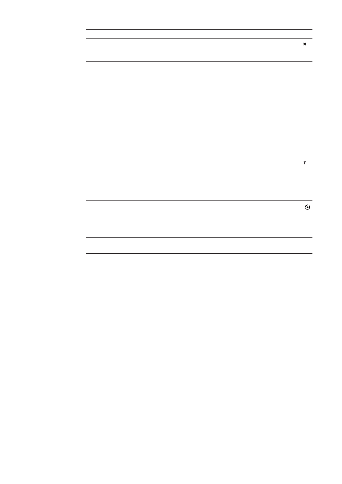
The firewall must be configured as follows in order to use the different Fronius Datamanager functions:
49049/UDP
output
Sending service messages x - Connecting to datalogger via ‘Fro-
nius Solar.web’
Connecting to datalogger via ‘Fro-
nius Solar.access’ or
'Fronius Solar.service'
Access to the Fronius Datamanager web interface
Service messages are sent via Fronius Solar.web.
Configure the firewall so that the IP address of Fronius Datamanager can send data to port
49049/UDP from "fdmp.solarweb.com."
DSL routers mostly enable you to send data to the internet and, therefore, do not normally
have to be configured.
To access the Fronius Datamanager web interface outside of the LAN:
- Configure the network router so that requests are forwarded to port 80/TCP on Fronius
Datamanager
x--
-xx
--x
15015/TCP
input
80/TCP
input
7
Page 10

Sending service
messages via a
DSL Internet connection
Normally, no additional router configuration is required for a regular DSL Internet connection for accessing 'Fronius Solar.web' and/or sending service messages, because connections from the LAN to the Internet are open.
Using Fronius Solar.web and sending service
messages
Calculating Data
Volumes
However, an internet connection is required to use Fronius Solar.web and send service
messages.
Fronius Datamanager cannot connect to the Internet spontaneously. A router must be
used for a DSL connection to the Internet.
When operating the Fronius Datamanager, data is generated and needs to be transmitted
online.
In order to select a suitable Internet connection it is necessary to calculate the data volume.
Detailed information on the calculation of data volumes can be found on our home page at
http://www.fronius.com in the operating instructions for the Fronius Datamanager (Galvo/
Symo).
8
Page 11

Controls, connections and indicators
EN-US
Safety
Controls, Connections and Indicators
WARNING! Operating the device incorrectly can cause serious injury and dam-
age. Do not use the functions described until you have thoroughly read and understood the following documents:
- these operating instructions
- all operating instructions for system components, especially the safety rules
(1)
(2)
(3)
(4)
(5)
(6)
(7)
(8)
No. Function
(1) Supply LED
- Lights up green: When sufficient power is coming from Fronius Solar Net;
Fronius Datamanager is operational
- Does not light up: When no power or not enough power is coming from Fronius Solar Net; an external power supply is required
- Flashes red: During an update process
IMPORTANT! Do not interrupt the power supply during an update process.
- Lights up red: the update process failed
9
Page 12
No. Function
(2) Connection LED
- lights up green: When there is an active connection within Fronius Solar
Net
- Lights up red: When there is an interrupted connection within Fronius Solar
Net
(3) IP switch
for changing the IP address:
A Default IP address "169.254.0.180"
Fronius Datamanager uses the fixed IP address 169.254.0.180;
the fixed IP address is used for a direct connection to a PC via LAN
without first having to pre-configure the PC
B Assigned IP address
Fronius Datamanager operates using an assigned IP address (factory
setting 192.168.1.180);
The IP address can be set on the Fronius Datamanager web interface.
(4) WLAN LED
- Flashes green: Fronius Datamanager is in service mode (IP switch on the
Fronius Datamanager plug-in card is in position A)
- Lights up green: When there is an existing network connection
- Lights up red: When there is no existing network connection
- Does not light up: Plug-in card without WLAN
(5) Solar Web LED connection
- Lights up green: When there is an existing connection to Fronius Solar.web
- Lights up red: When there is no connection to Fronius Solar.web, but one
is required
- Does not light up: When no connection to Fronius Solar.web is required
(6) LAN connection socket
Ethernet interface colored blue for connecting the Ethernet cable
(7) I/Os
digital inputs and outputs
Digital inputs: I/O 0 – I/O 3, I 4 – I 9
voltage level: low = min. 0 V – max. 1.8 V; high = min. 3 V – max. 30 V
input currents: dependent on input voltage; input resistance = 46 kOhm
Digital outputs: I/O 0 – I/O 3
Switching capacity when supplied by the Datamanager plug-in card: 3.2 W,
10.7 V in total for all 4 digital outputs
Switching capacity when supplied by an external power supply with min. 10.7 –
max. 24 V DC, connected to Uint / Uext and GND: 1 A, 10.7 – 24 V DC (depending on the external power supply) per digital output
The connection to the I/Os is made via the supplied mating connector.
(8) WLAN Antenna Socket with WLAN antenna
(only for versions with WLAN)
for connecting the WLAN antenna
10
Page 13
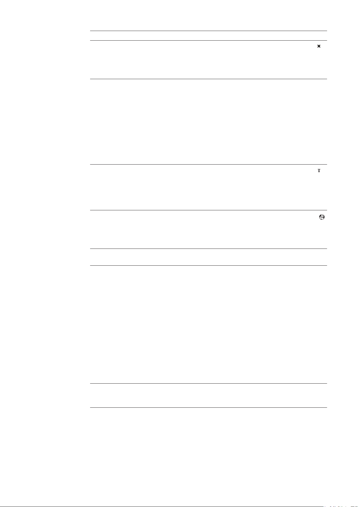
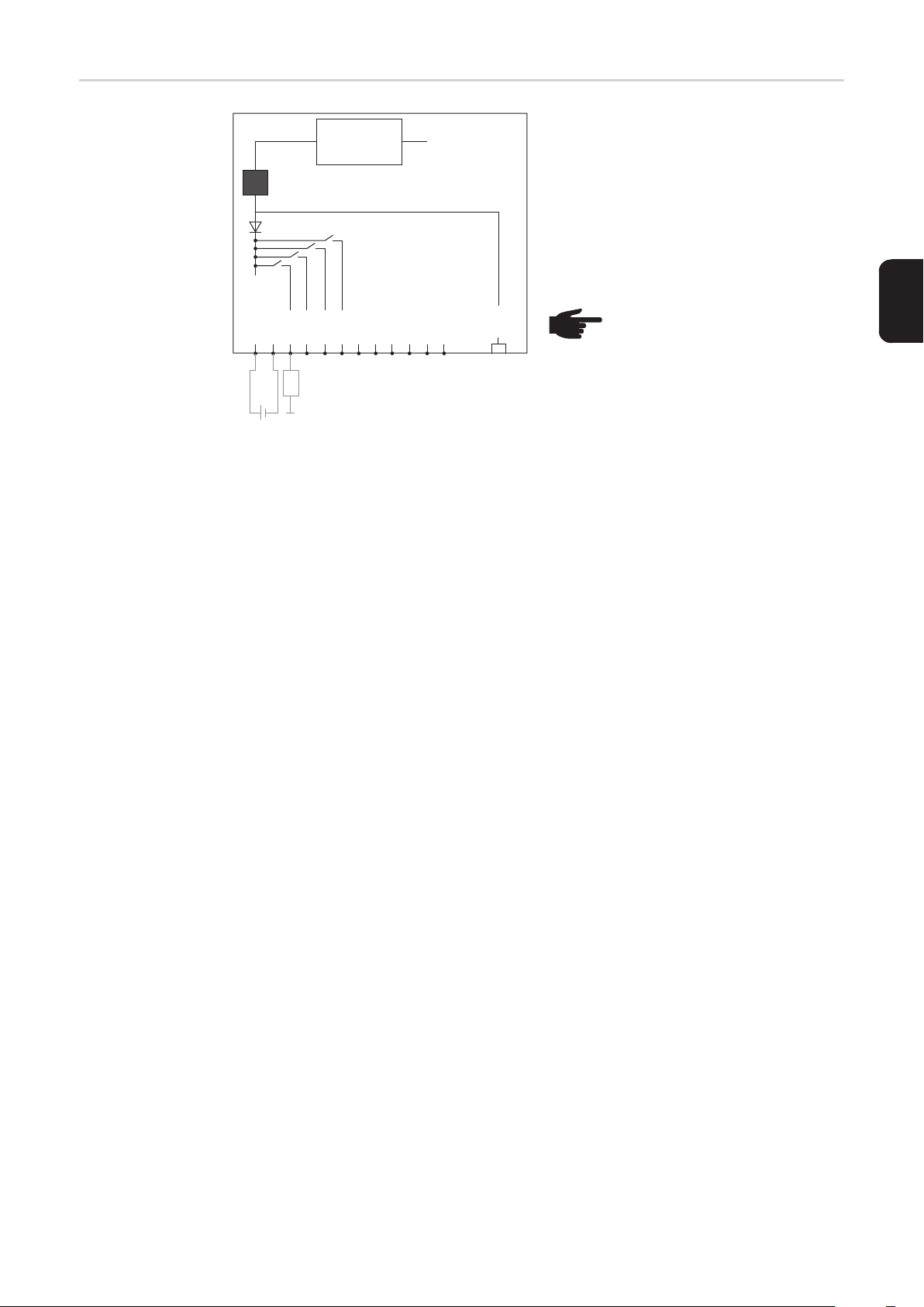
Schematic Connection of I/Os
10,7 V DC
(2) 300 mA
Uint / Uext
GND
I/O 0
(4)
(3)
+ -
10,7 - 24 V DC
I/O 1
I/O 2
(1)
I/O 3
I 4
I 5
I 6
230 V AC
I 7
I 8
I 9
Solar Net
IN
Supply via Datamanager plug-in card:
(1) Power supply
(2) Current limit
Supply via external power supply:
(3) External power supply
(4) Load
NOTE! When the supply is via an
external power supply, the external power supply must be galvanically isolated.
EN-US
11
Page 14

Cabling
Fronius Solar Net
clients
Fronius Solar Net
Client Cabling
Requirements for
the Solar Net Data
Cables
Inverters with Fronius Datamanager or Fronius Com Card, DATCOM components with external housing or other DATCOM components will hereinafter be referred to as Fronius Solar Net.
The data connection for the Fronius Solar Net client is a 1:1 connection using 8-pin data
cables and RJ-45 plugs.
The overall line length in a Fronius Solar Net ring must not exceed 1000 m.
Shielded CAT5 (new) and CAT5e (old) cables compliant with ISO 11801 and EN 50173
must be used for the Fronius Solar Net client cabling. Other cables are not permitted.
IMPORTANT! Do not use ISO/IEC-11801 U/UTP cables!
Permitted cables:
- S/STP
- F/STP
- S/FTP
The shield must be crimped onto a CAT5-compatible shielded plug.
- F/FTP
- SF/FTP
- S/UTP
- F/UTP
- U/FTP
- U/STP
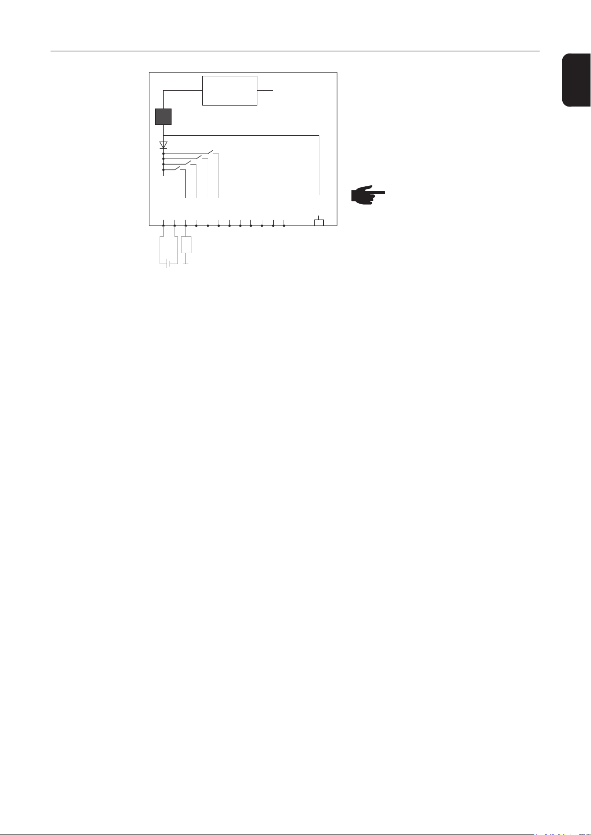
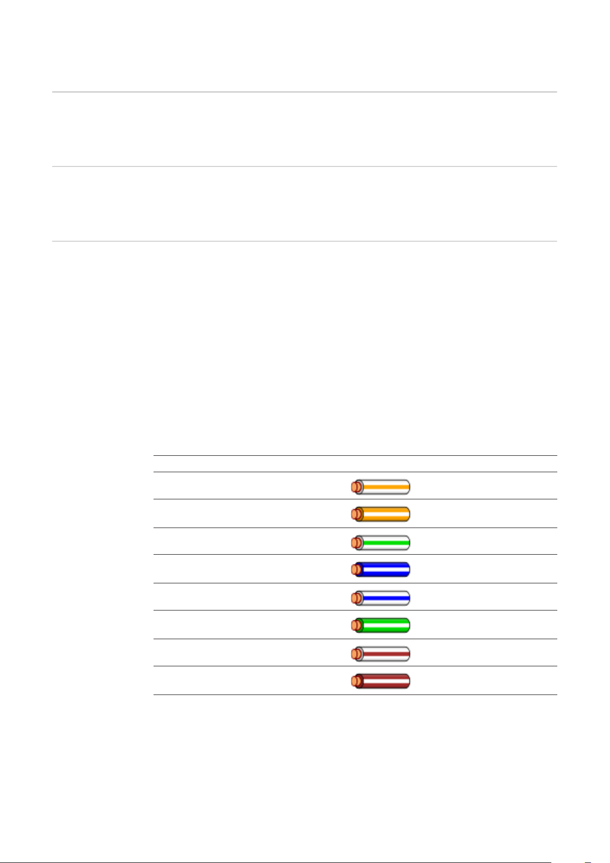
Due to the fact that the wires in Ethernet cables are twisted, you must make sure the twisted pairs of wires are assigned correctly for cabling in accordance with TIA/EIA-568B:
Fronius Solar Net contact Pair no. Color
1 +12 V 3 white/orange line
2 GND 3
3 TX+ IN, RX+ OUT 2 white/green line
4 RX+ IN, TX+ OUT 1
5 RX- IN, TX- OUT 1 white/blue line
6 TX- IN, RX- OUT 2
7 GND 4 white/brown line
8 +12 V 4
Cabling compliant with TIA/EIA-568B
orange/white line
or orange
blue/white line
or blue
green/white line
or green
brown/white line
or brown
12
- Make sure that the wires are assigned correctly.
- When setting up an independent ground connection (e.g., in patch panels), make sure
that the shield is grounded on one side of the cable only.
Page 15

The following structured cabling standards must generally be observed:
- EN 50173-1 for Europe
- ISO/IEC 11801:2002 internationally
- TIA/EIA 568 for North America
Rules for use of copper cables apply.
EN-US
Preassembled
data cables
The following preassembled data cables are available from Fronius:
- CAT5 cable 1 m ... 43,0004,2435
- CAT5 cable 20 m ... 43,0004,2434
- CAT5 cable 60 m ... 43,0004,2436
The cables listed above are 8-pin, 1:1 LAN network cables, shielded and twisted, including
RJ 45 plugs.
IMPORTANT! Data cables are not UV resistant. They should be protected from sunlight
when laid outdoors.
13
Page 16

Inserting Fronius Datamanager into an inverter
General Provided the Fronius Datamanager plug-in card is not fitted as standard in the inverter, the
plug-in card must be inserted into the inverter in accordance with the operating or installation instructions of the inverter in question. Please note the safety and warning information
in your inverter's operating instructions.
IMPORTANT! Before inserting the Fronius Datamanager plug-in card, remove any existing Fronius Power Control Card, or Fronius Modbus Card!
Safety
WARNING! An electric shock can be fatal. Danger from grid voltage and DC volt-
age from solar modules.
- The connection area should only be opened by a licensed electrician.
- The separate power stage set area should only be disconnected from the
connection area after first being disconnected from the grid power.
- The separate power stage set area should only be opened by Fronius-trained
service personnel.
Before making any connections, make sure that the AC and DC sides are disconnected from the inverter, e.g.:
- Switch off the AC automatic circuit breaker for the inverter
- Cover solar modules
Please observe the 5 safety rules.
WARNING! An electric shock can be fatal. Danger from residual voltage from capacitors.
You must wait until the capacitors have discharged.
NOTE! Follow general ESD precautions when handling plug-in cards.
14
Page 17

Installing Fronius Datamanager in Fronius Solar Net
EN-US
Installing Inverters with Fronius
Datamanager in
Fronius Solar Net
IN
DATCOM
IN OUT
5
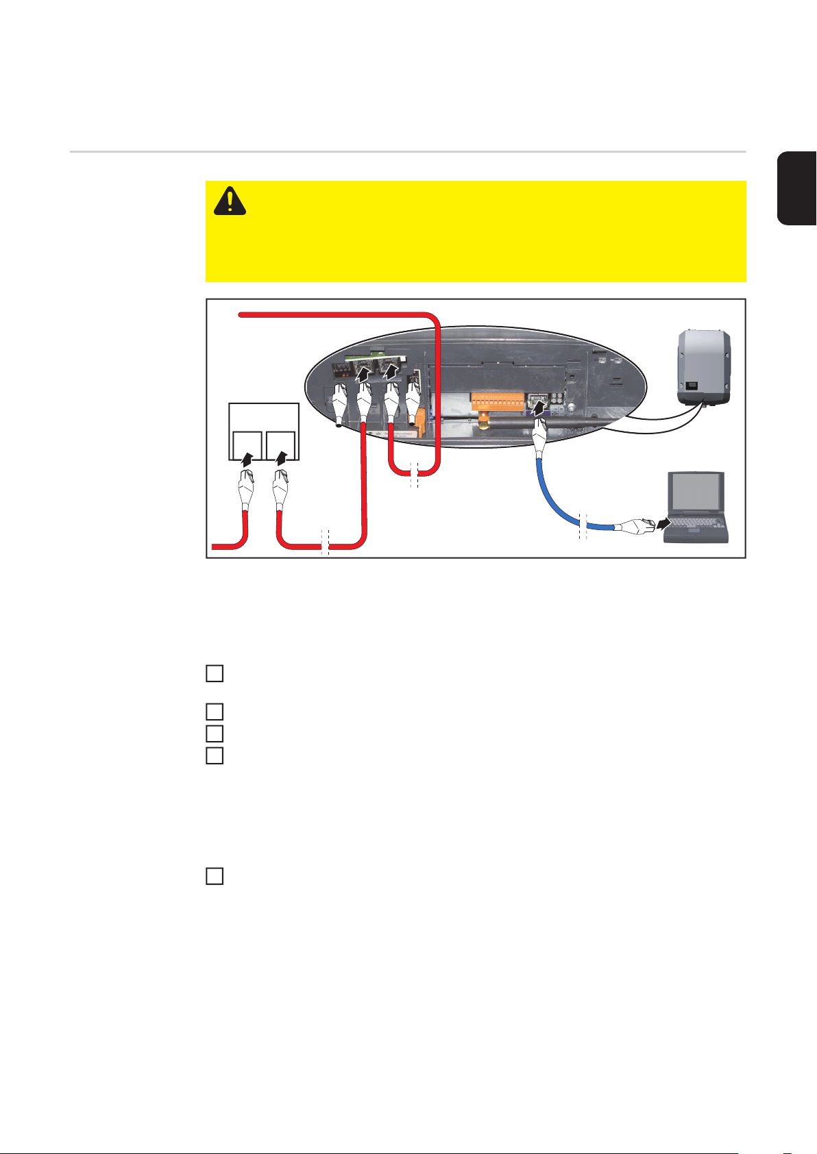
CAUTION! DATCOM components and/or the PC/laptop may be seriously damaged if the Ethernet or Solar Net cables are connected incorrectly to the Fronius
Datamanager.
- The Ethernet cable should only be inserted into the LAN connection socket
(colored blue).
- The Solar Net cable should only be inserted into the inverter Solar Net IN or
Solar Net OUT connection sockets.
6
3
**
4
****
1
2
* Terminating plug, if only one inverter with Fronius Datamanager is linked to a PC
or if there is no further Solar Net subscriber on the Solar Net connection socket.
** Solar Net Cable, if an inverter with Fronius Datamanager is linked to a PC and oth-
er DATCOM components
Insert and lay the Ethernet cable in the inverter like a data communication cable in ac-
1
cordance with the operating instructions for the inverter.
Insert the Ethernet cable into the LAN connection socket.
2
Insert the Ethernet cable into the PC/laptop or into a suitable network connection sock-
3
et.
If only one inverter with Fronius Datamanager is being linked to a PC:
4
Insert a terminating plug into the Solar Net IN connection socket and the Solar Net
OUT connection socket
If other DATCOM components are connected to the network, besides the inverter with
Fronius Datamanager:
Insert the Solar Net cable into the Solar Net IN connection socket and the Solar Net
OUT connection socket.
Connect the other DATCOM components.
5
IMPORTANT! A terminating plug must be inserted into every empty Solar Net connection socket of the last DATACOM component.
15
Page 18

Installing Fronius Datamanager – Overview
Safety
Starting Up for
the First Time
WARNING! Operating the device incorrectly can cause serious injury and dam-
age. Do not use the functions described until you have thoroughly read and understood the following documents:
- these operating instructions
- all operating instructions for system components, especially the safety rules
NOTE! Installing Fronius Datamanager requires knowledge of network technology.
Insert Fronius Datamanager into the inverter
1
See section "Inserting Fronius Datamanager into an inverter"
Insert blue Ethernet cable into Fronius Datamanager (LAN connection socket)
2
Insert terminating plug into Fronius Datamanager (Solar Net IN connection socket)
3
Insert blue Ethernet cable into the PC/laptop
4
See section "Installing Fronius Datamanager in Fronius Solar Net"
Turn off WLAN on PC/laptop (to avoid network conflicts)
5
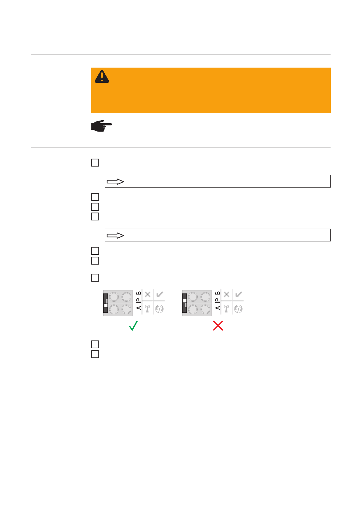
Adjust network settings for Fronius Datamanager on PC/laptop:
6
"Obtain an IP address automatically (DHCP)" must be activated
Switch IP switch on Fronius Datamanager to position - A -
7
16
Close the inverter and switch it on
8
After about 1 minute, open the browser on the PC/laptop and enter the following ad-
9
dress (web server works with Internet Explorer 9 or higher, Chrome or Firefox):
http://169.254.0.180
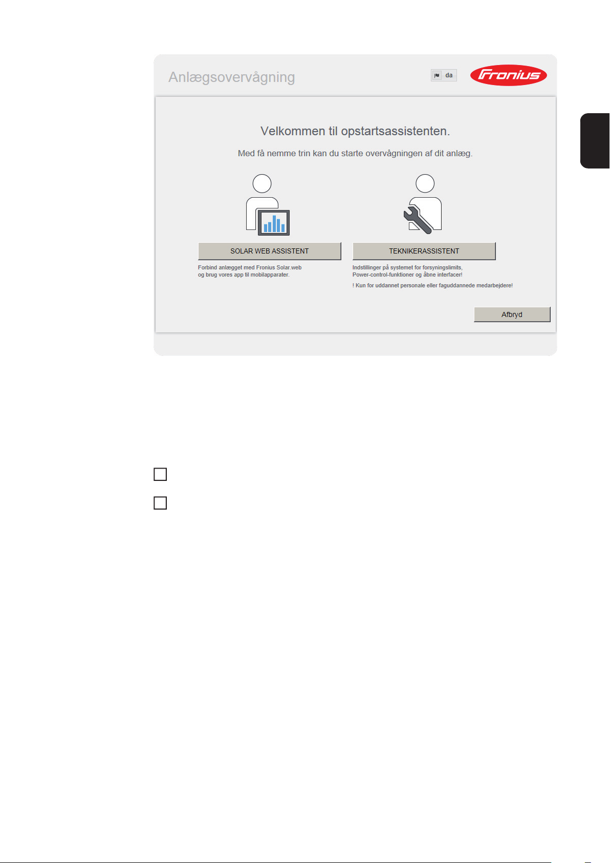
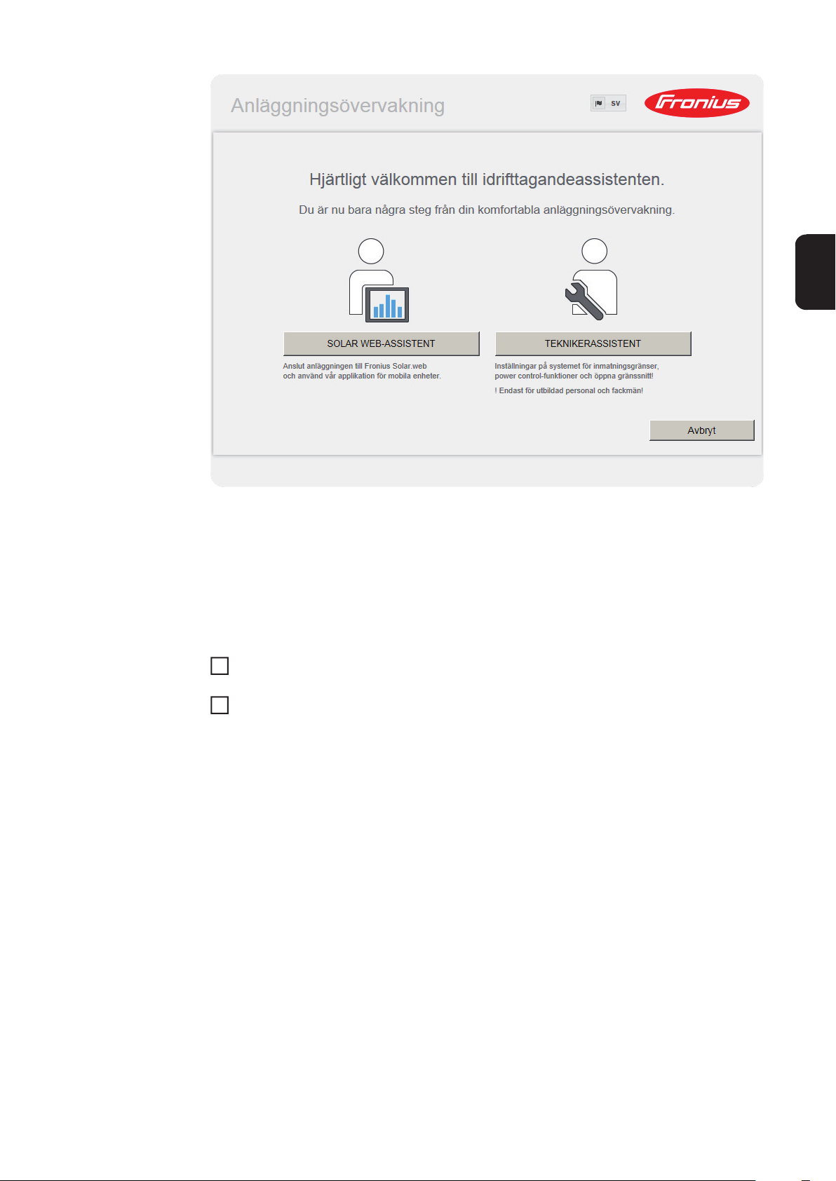
The start page of the Commissioning Wizard appears.
Page 19

The Technician Wizard is designed for the installer and includes standard-specific settings.
If the Technician Wizard is run, it is essential to note down the assigned service password.
This service password is required to configure the UC Editor and Counter menu items.
If the Technician Wizard is not run, no specifications for power reduction are set.
EN-US
The Solar Web Wizard must be run.
If necessary, run the Technician Wizard and follow the instructions
6
Run the Solar Web Wizard and follow the instructions
7
The Fronius Solar.web start page appears
or
The Fronius Datamanager website opens.
IMPORTANT: To establish a connection to Fronius Datamanager, the end device in question (e.g., laptop, tablet) must be configured as follows:
- "Obtain an IP address automatically (DHCP)" must be activated
17
Page 20

Technical Data
Technical Data
Memory capacity 16 MB
Supply voltage 230 V AC
Energy consumption typ. 1.4 W (without WiFi)
typ. 2.2 W (with WiFi)
Dimensions 132 x 103 x 22 mm
5.2 x 4.1 x 0.9 in.
Ethernet (LAN) RJ 45, 100 MB
WiFi IEEE 802.11b/g Client
RS 485 (Fronius Solar Net) RJ 45
Ambient temperature -20 – +65°C
-4 – +149°F
Solar Net power approx. 3 W
max. 3 DATCOM components *
I/O Connection Specifications
Voltage level of digital inputs low = min. 0 V – max. 1.8 V
high = min. 3 V – max. 30 V
Input currents of digital inputs depending on the input voltage;
input resistance = 46 kOhm
Switching capacity of digital outputs when
supplied by the Datamanager plug-in card
(minus other Solar Net participants)
Switching capacity of digital outputs when
supplied by an external power supply with
min. 10.7 – max. 24 V DC
Max. switchable energy of digital outputs 76 mJ
* When sufficient power is coming from Fronius Solar Net, the green LED lights up
on every DATCOM component.
If the green LED does not light up, the power pack available from Fronius should
be inserted into the 12 V power pack connection socket of the DATCOM component.
Check the cable and plug connections if necessary.
(depending on the external power supply)
in total for all 4 digital outputs
3.2 W, 10.7 V
1 A, 10.7 – 24 V DC
per digital output
(per output)
18
Page 21

Kort oversigt
Generelt ..................................................................................................................................................... 21
Generelle informationer til netværksadministratoren ................................................................................. 25
Betjeningselementer, tilslutninger og visninger.......................................................................................... 27
Kabelføring................................................................................................................................................. 30
Indsætning af Fronius Datamanager i vekselretteren ................................................................................ 32
Installation af Fronius Datamanager i Fronius Solar Net ........................................................................... 33
Installation af Fronius Datamanager - oversigt .......................................................................................... 34
Tekniske data............................................................................................................................................. 36
DA
Detaljerede informationer
Detaljerede informationer til Fronius Datamanager kan findes i den komplette betjeningsvejledning til Fronius Datamanager (Galvo/Symo) under solcelleelektronik / anlægsovervågning på vores hjemmeside under http://www.fronius.com.
19
Page 22

20
Page 23

Generelt
Generelt 'Fronius Datamanager' er en netværkskompatibel datalogger, som kombinerer 'Fronius
Com Card's' og 'Fronius Datalogger Web's' funktioner på et stikkort.
'Fronius Datamanager'-web-interface leverer et hurtigt overblik over solcelleanlægget.
Webinterfacet kan åbnes via en direkte forbindelse i intranettet eller ved konfigurering via
internettet.
'Fronius Datamanager' er udstyret med en overvågning af anlægget med automatisk alarmering, som er nem at konfigurere. Alarmeringen kan foregå via SMS, e-mail eller fax.
I forbindelse med 'Fronius solar.access' kan aktuelle data og arkivdata til solcelleanlæg
gemmes på en pc og analyseres. Det er muligt at indstille alle apparater i 'Fronius Solar
Net'.
I forbindelse med 'Fronius Solar.web' kan aktuelle data og arkivdata til solcelleanlæg hentes via internettet eller Fronius Solar.web App uden tidskrævende konfiguration. Dataene
sendes automatisk til 'Fronius Solar.web' fra 'Fronius Datamanager".
DA
Anvendelige
DATCOM-komponenter
Forudsætninger
for drift
'Fronius Datamanager'-stikkortet, der er installeret i vekselretteren, kan anvendes med følgende DATCOM-komponenter:
- op til 100 x Fronius-vekselretter
(inkl. vekselretteren, 'Fronius Datamanager' er installeret i)
- op til 10 x ‘Fronius Sensor Card’ eller ‘Fronius Sensor Box’
- op til 10 x ‘Fronius Public Display Card’ eller ‘Fronius Public Display Box’
- op til 1 x ‘Fronius Interface Card’ eller ‘Fronius Interface Box’
- op til 200 x ‘Fronius String Control’
Til dataudveksling via internettet skal der bruges en internetforbindelse:
- Ved kabelforbundne internetløsninger anbefaler Fronius en download-hastighed på
min. 512 kBit/s og en upload-hastighed på
min. 256 kBit/s.
- Til løsninger med mobiles internettjeneste anbefaler Fronius min. 3G-overførselsstandard med stabil signalstyrke.
Disse informationer giver ingen absolut garanti for korrekt funktion.
Høje fejlrater ved overførslen, svingninger ved modtagelsen eller afbrydelse i transmissionen kan påvirke 'Fronius Datamanager's' online-drift negativt.
Fronius anbefaler, at forbindelserne testes på stedet med mindstekravene.
Da 'Fronius Datamanager' fungerer som datalogger, må der ikke være andre dataloggere
i Fronius Solar Net Ring.
Kun en 'Fronius Datamanager' pr. Fronius Solar Net Ring
Følgende DATCOM-komponenter må ikke anvendes sammen med Fronius Datamanager
i en Fronius Solar Net Ring:
- Fronius Power Control Card / Box
- Fronius Modbus Card
- Fronius Datalogger Web
- Fronius Personal Display DL Box
- Fronius Datalogger easy / pro
21
Page 24

Til drift af 'Fronius Datamanager' skal stikkortet være monteret i inverteren.
'Fronius Datamanager'-stikkortet og 'Fronius Com Card' må ikke bruges samtidig i inverteren.
Informationer om
radiomærkning
'Fronius Datamanager'-stikkort med WLAN er udstyret med et trådløst modul.
Trådløse moduler har mærkningspligt i USA efter FCC:
FCC
Dette apparat er i overensstemmelse med grænseværdierne for digitale apparater i klasse B efter del 15 i FCC-bestemmelserne. Disse grænseværdier
giver den nødvendige beskyttelse mod skadelige forstyrrelser i beboelsesrum. Dette apparat genererer og anvender højfrekvens-energi og kan forstyrre radiokommunikationen, hvis det ikke anvendes i overensstemmelse
med anvisningerne. Der er dog ingen garanti for, at der ikke forekommer fejl
i en bestemt installation.
Hvis dette apparat er årsag til fejl i radio- eller tv-modtagelsen, hvilket kan
kontrolleres ved at tænde og slukke for apparatet, anbefales det, at fejlene
afhjælpes med en eller flere af følgende foranstaltninger:
- Justér modtageantennen eller stil den i en anden position.
- Gør afstanden mellem apparatet og modtageren større.
- Slut apparatet til en anden strømkreds, hvor modtageren ikke er tilsluttet.
- Kontakt forhandleren eller en erfaren radio- / tv-tekniker for yderligere
hjælp.
FCC ID: PV7-WIBEAR11N-DF1
Industry Canada RSS
Dette apparat er i overensstemmelse med de licensfri Industry Canada
RSS-normer. Driften skal foregå under følgende betingelser:
(1) Apparatet må ikke udsende skadelige forstyrrelser
(2) Apparatet skal kunne klare enhver påvirkning fra forstyrrelser inklusive
påvirkninger fra forstyrrelser, som kan føre til forringelse af driften.
IC ID: 7738A-WB11NDF1
Medmindre producenten udtrykkeligt har tilladt det, er ændring eller ombygning af det trådløse modul ikke tilladt og vil i givet fald føre til tab af brugerens driftsrettigheder til apparatet.
22
Page 25

Konfigurationseksempler
'Vekselretter med 'Fronius Datamanager' koblet sammen med en pc:
(1) Vekselretter
(1)
(2) Fronius Datamanager
+
(3) Termineringer (2x)
(4) Pc / laptop
DA
(4)
IN
(3)
(2)
LAN / WLAN
OUT
BEMÆRK! Ved sammenkobling af vekselrettere med 'Fronius Datamanager'
med en pc skal der sættes en terminering i hver af vekselretterens tilslutninger
Solar Net IN og Solar Net OUT.
‘Vekselretter (Fronius Galvo eller Fronius Symo) koblet sammen med ‘Fronius Datamanager‘‘ med flere vekselrettere (Fronius IG Plus V), en ‘Fronius Sensor Box’ og
en pc:
(1)
(4) (7)
(6)
OUT
IN
(2)
IN
OUT
LAN / WLAN
(3)
(1) Vekselretter
(f.eks.: Fronius Galvo eller Fronius Symo)
+
(2) Fronius Datamanager
(3) Pc / laptop
(4) Vekselretter
(f.eks. Fronius IG Plus V)
+
(5) Fronius Com Card
(4)
IN
OUT
(5)
(6) Fronius Sensor Box
(7) Vekselretter
(f.eks. Fronius IG Plus V)
+
(8) Fronius Com Card
(9) Terminering
OUT
IN
(8)
(9)
23
Page 26

BEMÆRK! Ved sammenkobling af flere DATCOM-komponenter i forbindelse
med en vekselretter med 'Fronius Datamanager':
Forbind f.eks. vekselretterens Solar Net IN-tilslutning og de næste DATCOMkomponenters OUT-tilslutning med datakablet. På de sidste DATCOM-komponenters frie Solar Net-tilslutninger skal der indsættes en terminering.
24
Page 27

Generelle informationer til netværksadministratoren
Forudsætninger
BEMÆRK! 'Fronius Datamanager's' netværkskonfiguration forudsætter kend-
skab til netværksteknologien.
DA
Hvis 'Fronius Datamanager' integreres i et eksisterende netværk, skal 'Fronius Datamanager's' adressering tilpasses til netværket.
f.eks.: Netværks-adresseområde = 192.168.1.x, subnet-maske = 255.255.255.0
- ‘Fronius Datamanager’ skal tildeles en IP-adresse mellem 192.168.1.1 og
192.168.1.254.
- Den valgte IP-adresse må ikke anvendes i netværket endnu.
- Subnet-masken skal svare til det eksisterende netværk (f.eks.255.255.255.0).
Hvis ‘Fronius Datamanager’ afsender servicemeldinger eller sender data til ‘Fronius Solar.web’, skal der indtastes en gateway-adresse og en DNS-server-adresse. Via gatewayadressen får 'Fronius Datamanager' en forbindelse til internettet. DSL-routerens IP-adresse kan bruges som gateway-adresse.
VIGTIGT!
- ‘Fronius Datamanager’ må ikke have samme IP-adresse som pc'en / laptoppen!
- 'Fronius Datamanager' kan ikke koble sig selv til internettet. Ved en DSL-tilslutning
skal en router opbygge forbindelsen til internettet.
Hvis forbindelsen til netværket skal etableres via WLAN, skal 'Fronius Datamanager' være
udstyret med WLAN-funktionen og med en WLAN-antenne, der passer til vekselretteren.
Almindelige firewall-indstillinger
For at kunne udføre 'Fronius Datamanager's' forskellige funktioner skal der indstilles en firewall på følgende måde:
49049/UDP
udgang
Afsendelse af servicemeldinger x - Forbindelse til dataloggeren via
'Fronius Solar.web'
Forbindelse til dataloggeren via
'Fronius Solar.access' eller
'Fronius Solar.service'
Adgang til 'Fronius Datamanager's' web-interface
Servicemeldingerne afsendes via Fronius Solar.web.
Konfigurer din firewall, så IP-adressen til Fronius Datamanager kan sende data til porten
49049/UDP fra "fdmp.solarweb.com".
DSL-routeren giver mulighed for forsendelse af data til internettet og skal derfor som regel
ikke konfigureres.
For at få adgang til Fronius Datamanager's web-interface uden for LAN:
- Konfigurer netværks-routeren, så forespørgsler på port 80/TCP ledes videre til Fronius Datamanager
x--
-xx
--x
15015/TCP
indgang
80/TCP
indgang
25
Page 28

Afsendelse af servicemeldinger
ved DSL-internetforbindelse
Ved en almindelig DSL-internetforbindelse er 'Fronius Solar.web' og afsendelse af servicemeldinger for det meste mulig uden ekstra konfiguration af routeren, da forbindelserne fra
LAN er åbne til internettet.
Brug af ‘Fronius
Solar.web’ og afsendelse af servicemeldinger
Beregning af datavolumen
Til brug af 'Fronius Solar.web' eller afsendelse af servicemeldinger skal der være en internetforbindelse.
'Fronius Datamanager' kan ikke koble sig selv til internettet. Ved en DSL-tilslutning skal en
router opbygge forbindelsen til internettet.
Ved drift af 'Fronius Datamanager' samles der data, som skal overføres via internettet.
Beregning af datavolumenet er nødvendig for valg af den rigtige internet-tilslutning.
Detaljerede informationer til beregning af datavolumenet kan findes på vores hjemmeside
under http://www.fronius.com i betjeningsvejledningen til ‘Fronius Datamanager‘ (Galvo/
Symo).
26
Page 29

Betjeningselementer, tilslutninger og visninger
Sikkerhed
Betjeningselementer, tilslutninger og visninger
ADVARSEL! Fejlbetjening kan medføre alvorlige personskader og materielle
skader. Anvend først de beskrevne funktioner, når følgende dokumenter er læst
og forstået fuldstændigt:
- denne betjeningsvejledning
- samtlige betjeningsvejledninger til systemkomponenterne, især sikkerhedsforskrifterne
(1)
(2)
(3)
(4)
(5)
DA
(6)
(7)
(8)
Nr. Funktion
(1) LED-forsyning
- Lyser grønt: ved tilstrækkelig strømforsyning fra 'Fronius Solar Net'; 'Fronius Datamanager er driftsklar
- Lyser ikke: ved mangelfuld eller ingen strømforsyning fra 'Fronius Solar
Net' - der kræves en ekstern strømforsyning
- Blinker rødt: under et opdateringsforløb
VIGTIGT! Afbryd ikke strømforsyningen under opdateringsforløb.
- Lyser rødt: opdateringsforløbet mislykkedes
27
Page 30

Nr. Funktion
(2) LED-forbindelse
- Lyser grønt: ved etableret forbindelse inden for 'Fronius Solar Net'
- Lyser rødt: ved afbrudt forbindelse inden for 'Fronius Solar Net'
(3) Kontakt IP
til ændring af IP-adresse:
A indstillet IP-adresse ‘169.254.0.180’
‘Fronius Datamanager’ arbejder med den faste IP-adresse
169.254.0.180;
den faste IP-adresse bruges til direkte forbindelse med en pc via LAN,
uden forudgående konfiguration af pc'en
B Tildelt IP-adresse
'Fronius Datamanager' arbejder med en tildelt IP-adresse (standardindstilling 192.168.1.180);
IP-adressen kan indstilles på 'Fronius Datamanager's' web-interface.
(4) LED WLAN
- blinker grønt: Fronius Datamanager er i service-modus (kontakt IP på Fronius Datamanager-stikkortet er på position A)
- Lyser grønt: ved etableret netværks-forbindelse
- Lyser rødt: ved ikke-etableret netværks-forbindelse
- Lyser ikke: Stikkort uden WLAN
(5) LED-forbindelse Solar Web
- Lyser grønt: ved etableret forbindelse til 'Fronius Solar.web'
- Lyser rødt: ved krævet, men ikke etableret forbindelse til 'Fronius Solar.web'
- Lyser ikke: hvis der ikke kræves forbindelse til 'Fronius solar.web"
(6) Tilslutning LAN
Ethernet-interface med blå markering, til tilslutning af ethernet-kablet
(7) I/Oer
digitale ind- og udgange
Digitale indgange: I/O 0 - I/O 3, I 4 - I 9
Spændingsniveau: low = min. 0 V - maks. 1,8 V; high = min. 3 V - maks. 30 V
Indgangsstrøm afhængigt af indgangsspænding; indgangsmodstand = 46
kOhm
Digitale udgange: I/O 0 - I/O 3
Koblingsfunktion ved forsyning via Datamanager-stikkortet: 3,2 W, 10,7 V som
sum for alle 4 digitale udgange
Koblingsfunktion ved forsyning via en ekstern strømforsyning med min. 10,7 maks. 24 V DC, tilsluttet til Uint / Uekst og GND: 1 A, 10,7 - 24 V DC (afhængigt
af den eksterne strømforsyning) pr. digital udgang
Tilslutningen til I/Oer foretages med et medfølgende krydsstik.
(8) WLAN-antenneudgang med WLAN-antenne
(kun ved modeller med WLAN)
til tilslutning af WLAN-antennen
28
Page 31

Skematiske tilslutningsmuligheder for I/Oer
10,7 V DC
(2) 300 mA
Uint / Uext
GND
I/O 0
(4)
(3)
+ -
10,7 - 24 V DC
I/O 1
I/O 2
(1)
I/O 3
I 4
I 5
I 6
230 V AC
I 7
I 8
I 9
Solar Net
IN
Forsyning via Datamanager-stikkortet:
(1) Netdel
(2) Strømbegrænsning
Forsyning via en ekstern netdel:
(3) Ekstern netdel
(4) Last
BEMÆRK! Ved forsyning via en
ekstern netdel skal den eksterne
netdel være separeret galvanisk.
DA
29
Page 32
Kabelføring
Fronius Solar
Net-deltager
Kabelføring til
Fronius Solar
Net-deltagere
Forudsætninger
for Solar Net-datakablerne
Vekselrettere med Fronius Datamanager eller Fronius Com Card, DATCOM-komponenter
med eksternt hus eller andre DATCOM-komponenter betegnes efterfølgende som Fronius
Solar Net-deltagere.
Dataforbindelsen til Fronius Solar Net-deltagerne etableres med en 1:1-forbindelse med 8polede datakabler og RJ-45-stik.
Ledningernes samlede længde i en Fronius Solar Net-ring må maks. være 1000 m.
Til sammenkobling af Fronius Solar Net-deltagerne med kabler må der udelukkende bruges afskærmede CAT5 (nye) og CAT5e (gamle) kabler i henhold til ISO 11801 og
EN50173.
VIGTIGT! U/UTP-kabler i henhold til ISO/IEC-11801 må ikke anvendes!
Tilladte kabler:
- S/STP
- F/STP
- S/FTP
Afskærmningen skal crimpes på et afskærmet stik, som er godkendt til CAT5.
- F/FTP
- SF/FTP
- S/UTP
- F/UTP
- U/FTP
- U/STP
Da lederne i ethernet-kabler er snoede, er det vigtigt, at forsyningen af de snoede lederpar
sker i henhold til kabelføringen efter TIA/EIA-568B:
Kontakt Fronius Solar Net Par-nr. Farve
1 +12 V 3 Hvid / orange streg
2 GND 3
3 TX+ IN, RX+ OUT 2 Hvid / grøn streg
4 RX+ IN, TX+ OUT 1
5 RX- IN, TX- OUT 1 Hvid / blå streg
6 TX- IN, RX- OUT 2
7 GND 4 Hvid / brun streg
8 +12 V 4
Kabelføring efter TIA/EIA-568B
Orange / hvid streg
eller orange
Blå / hvid streg
eller blå
Grøn / hvid streg
eller grøn
Brun / hvid streg
eller brun
30
- Sørg for, at tildelingen af lederne er korrekt.
- Ved selvstændig jordforbindelse (f.eks. i patch-paneler) er det vigtigt, at afskærmningen kun er jordforbundet på den ene side af kablet.
Page 33

Generelt skal de følgende standarder for struktureret kabelføring overholdes:
- For Europa EN50173-1
- Internationalt ISO/IEC 11801:2002.
- For Nordamerika TIA/EIA 568
Reglerne for anvendelse af kobberkabler gælder.
DA
Forkonfektionerede datakabler
Fronius leverer følgende forkonfektionerede datakabler:
- CAT5 kabel 1 m ... 43,0004,2435
- CAT5 kabel 20 m ... 43,0004,2434
- CAT5 kabel 60 m ... 43,0004,2436
De angivne kabler er 8-polede 1:1 LAN netværkskabler, afskærmede og snoede, inkl.
RJ45-stik.
VIGTIGT! Datakablerne er ikke UV-bestandige. Beskyt datakablerne mod solens stråler,
hvis de lægges udendørs.
31
Page 34
Indsætning af Fronius Datamanager i vekselretteren
Generelt Hvis 'Fronius Datamanager'-stikkortet ikke findes seriemæssigt i vekselretteren, skal stik-
kortet sættes ind i vekselretteren efter betjenings- eller installationsvejledningen til den pågældende vekselretter. Overhold sikkerhedsanvisningerne og advarslerne i
betjeningsvejledningerne til vekselretterne.
VIGTIGT! Fjern et eventuelt 'Fronius Power Control Card' eller 'Fronius Modbus Card' før
indsætning af 'Fronius Datamanager'-stikkortet!
Sikkerhed
ADVARSEL! Elektriske stød kan være dræbende. Fare på grund af lysnetspæn-
ding og solcellemodulernes DC-spænding.
- Forbindelsesområdet må kun åbnes af autoriserede el-installatører.
- Effektenhedernes separate område må kun adskilles fra forbindelsesområdet i spændingsfri tilstand.
- Effektenhedernes separate område må kun åbnes af Fronius-uddannede
servicemedarbejdere.
Inden tilslutningsarbejderne skal der sørges for, at AC- og DC-siden før vekselretteren er spændingsfri, f.eks.:
- Sluk for AC-sikringsautomaten til vekselretteren, så den er spændingsfri
- Dæk solcellemodulerne til
Overhold de 5 sikkerhedsregler.
ADVARSEL! Elektriske stød kan være dræbende. Fare på grund af restspænding fra kondensatorer.
Vent, til kondensatorernes udladningstid er gået.
BEMÆRK! Overhold de almindelige ESD-bestemmelser før anvendelse af stikkort.
32
Page 35
Installation af Fronius Datamanager i Fronius Solar
Net
Installation af
vekselretter med
'Fronius Datamanager' i 'Fronius
Solar Net'
IN
DATCOM
IN OUT
5
FORSIGTIG! Fare for alvorlige materielle skader på DATCOM-komponenterne
eller på pc'en / laptoppen, hvis ethernet- eller Solar Net-kablerne sluttes forkert til
'Fronius Datamanager'.
- Tilslut udelukkende ethernet-kabler til LAN-tilslutningen (blå markering)
- Sæt udelukkende Solar Net-kablet ind i vekselretterens tilslutninger Solar
Net IN og Solar Net Out
6
3
**
4
****
1
2
DA
* Terminering, hvis der kun kobles én vekselretter med 'Fronius Datamanager' til en
pc, eller hvis der ikke er flere Solar Net-deltagere i Solar Net-tilslutningen
** Solar Net-kabel, hvis en vekselretter med 'Fronius Datamanager' kobles til en pc
og andre DATCOM-komponenter
Træk ethernetkablet ind i vekselretteren, og læg det som et datakommunikationskabel
1
som angivet i betjeningsvejledningen til vekselretteren
Indsætning af ethernetkabel i LAN-tilslutningen
2
Sæt ethernetkablet i pc'en / laptoppen eller i en tilsvarende netværkstilslutning
3
Hvis der kun kobles én vekselretter med 'Fronius Datamanager' til en pc:
4
Sæt en terminering i hver af tilslutningerne Solar Net IN og Solar Net OUT
Hvis der følger flere DATCOM-komponenter i nettet ud over vekselretteren med 'Fronius Datamanager':
Sæt Solar Net-kablet i vekselretterens tilslutning Solar Net IN
Forbind de øvrige DATCOM-komponenter med hinanden
5
VIGTIGT! På alle de sidste DATCOM-komponenters frie Solar Net-tilslutninger skal
der indsættes en terminering.
33
Page 36
Installation af Fronius Datamanager - oversigt
Sikkerhed
Første ibrugtagning
ADVARSEL! Fejlbetjening kan medføre alvorlige personskader og materielle
skader. Anvend først de beskrevne funktioner, når følgende dokumenter er læst
og forstået fuldstændigt:
- denne betjeningsvejledning
- samtlige betjeningsvejledninger til systemkomponenterne, især sikkerhedsforskrifterne
BEMÆRK! Installation af 'Fronius Datamanager' forudsætter kendskab til netværksteknologien.
Indsætning af 'Fronius Datamanager' i inverteren
1
Se afsnittet "Indsætning af Fronius Datamanager i inverteren"
Sæt det blå ethernet-kabel i 'Fronius Datamanager' (tilslutning LAN)
2
Sæt termineringen i 'Fronius Datamanager' (tilslutning Solar Net IN)
3
Sæt det blå ethernet-kabel i pc'en / laptoppen
4
Se afsnittet "Installation af Fronius Datamanager i Fronius Solar Net"
Sluk for WLAN på pc'en / laptoppen (for at undgå netværkskonflikter)
5
Tilpas netværksindstillingerne til 'Fronius Datamanager' på pc'en / laptoppen:
6
Aktivér IP-adresse automatisk (DHCP)" skal være aktiveret
Stil kontakten 'IP' på 'Fronius Datamanager' på position - A -
7
Luk inverteren, og tænd den
8
Åbn browseren på pc'en / laptoppen efter ca. 1 minut, og indtast den følgende adresse
9
(webserveren fungerer med Internet Explorer fra version 9, Chrome og Firefox):
http://169.254.0.180
Opstartsassistentens startside vises.
34
Page 37
Teknikerassistenten er beregnet til installatøren og indeholder normspecifikke indstillinger.
Hvis teknikerassistenten udføres, skal det tildelte service-password altid noteres ned. Dette service-password er nødvendigt til indstilling af menupunktet EVU-editor og tælleren.
Hvis teknikerassistenten ikke udføres, er der ikke foretaget indstillinger til kapacitetsreduceringen.
DA
Udførelse af Solar Web-assistenten er obligatorisk!
Udfør teknikerassistenten ved behov, og følg anvisningerne
6
Udfør Solar Web-assistenten ved behov, og følg anvisningerne
7
Fronius Solar Web-startsiden vises.
eller
Websiden til Fronius Datamanager vises.
VIGTIGT! Til opbyggelse af forbindelsen til Fronius Datamanager skal slutapparatet (f.eks.
laptop, tablet etc.) være indstillet på følgende måde:
- "Aktivér IP-adresse automatisk (DHCP)" skal være aktiveret.
35
Page 38

Tekniske data
Tekniske data
Lagerkapacitet 16 MByte
Forsyningsspænding 230 V AC
Energiforbrug typ. 1,4 W (uden WLAN)
typ. 2,2 W (med WLAN)
Mål 132 x 103 x 22 mm
5,2 x 4,1 x 0,9 in.
Ethernet (LAN) RJ 45, 100 MBit
WLAN IEEE 802.11b/g Client
RS 485 (Fronius Solar Net) RJ 45
Omgivelsestemperatur -20 - +65 ° C
-4 - +149 °F
Solar Net-effekt ca. 3 W
maks. 3 DATCOM-komponenter *
I/O tilslutnings-specifikationer
Spændingsniveau digitale indgange low = min. 0 V - maks. 1,8 V
high = min. 3 V - maks. 30 V
Indgangsstrøm digitale indgange Afhængigt af indgangsspændingen;
Indgangsspænding = 46 kOhm
Koblingsevne digitale udgange ved forsyning med Datamanager-stikkort
Koblingsevne digitale udgange ved forsyning via en ekstern strømforsyning med
min. 10,7 - maks. 24 V DC
Maks. omstillelig energi digitale udgange 76 mJ
* Ved tilstrækkelig strømforsyning i Fronius Solar Net lyser den grønne LED på hver
DATCOM-komponent.
Hvis den grønne LED ikke lyser, skal der sættes en strømforsyning, som leveres
af Fronius, i DATCOM-komponenternes 12 V-strømforsyningstilslutning.
Kontrollér kabel- og stikforbindelserne.
som sum for alle 4 digitale udgange
(fratrukket andre Solar Net-deltagere)
(afhængigt af ekstern strømforsyning)
3,2 W, 10,7 V
1 A, 10,7 - 24 V DC
pr. digital udgang
(pr. udgang)
36
Page 39

Kort översikt
Allmänt ....................................................................................................................................................... 39
Generell information för nätverksadministratören ...................................................................................... 43
Knappar, reglage, anslutningar och indikeringar ....................................................................................... 45
Kabeldragning............................................................................................................................................ 48
Isättning av ’Fronius Datamanager’ i växelriktaren .................................................................................... 50
Installation av ’Fronius Datamanager’ i ’Fronius Solar Net’. ...................................................................... 51
Installation av Fronius Datamanager - översikt.......................................................................................... 52
Tekniska data............................................................................................................................................. 54
Detaljerad information
I den fullständiga versionen av handboken till Fronius Datamanager hittar du detaljerad information om Fronius Datamanager (Galvo/Symo), se Solarelektronik/Anläggningsövervakning på vår webbplats www.fronius.com.
SV
37
Page 40

38
Page 41

Allmänt
Allmänt ’Fronius Datamanager’ är en nätverksklar datalogger som förenar funktionaliteten hos
’Fronius Com Card‘ och ’Fronius Datalogger Web‘ på ett instickskort.
Webbgränssnittet för ’Fronius Datamanager’ ger en snabb överblick över solcellsanläggningen.
Webbgränssnittet kan aktiveras via en direktförbindelse på Intranet eller vid en passande
konfiguration via Internet.
’Fronius Datamanager’ är försedd med en enkelt konfigurerbar anläggningsövervakning
med automatisk larmning. Den kan ske via SMS, e-post eller fax.
I kombination med ’Fronius Solar.access’ kan aktuella data och arkivdata från en solcellsanläggning sparas och utvärderas på en PC. Inställning av alla enheter kan göras i ’Fronius Solar Net’.
I kombination med ’Fronius Solar.web’ kan alla aktuella data och arkivdata från en solcellsanläggning aktiveras utan krävande konfigurationsarbeten via Internet eller appen ’Fronius
Solar.web’. ’Fronius Datamanager’ sänder datan automatiskt till ’Fronius Solar.web’.
SV
Användbara DATCOM-komponenter
Förutsättning för
drift
Det i växelriktaren monterade instickskortet för ’Fronius Datamanager’ kan användas med
följande DATCOM-komponenter:
- Upp till 100 x Fronius växelriktare
(inklusive den växelriktare, i vilken ’Fronius Datamanager’ har
monterats)
- Upp till 10 x ’Fronius Sensor Card’ eller ’Fronius Sensor Box’
- Upp till 10 x ’Fronius Public Display Card’ eller ’Fronius Public Display Box’
- Upp till 1 x ’Fronius Interface Card’ eller ’Fronius Interface Box’
- Upp till 200 x ’Fronius String Control’
Det krävs en lämplig Internet-förbindelse för ett felfritt datautbyte via Internet:
- Vid kabelbundna Internet-lösningar rekommenderar Fronius en nedladdningshastighet på minst 512 kBit/s och en uppladdningshastighet på
minst 256 kBit/s.
- Vid lösningar med mobila Internet-tjänster rekommenderar Fronius minst 3G med tillförlitlig signalstyrka som överföringsstandard.
De här uppgifterna utgör inte någon absolut garanti för en felfri funktion.
Många fel under överföringen, mottagningsvariationer och överföringsmissar kan påverka
online-driften för ’Fronius Datamanager’ negativt.
Fronius rekommenderar att testa förbindelser med minimikraven på monteringsplatsen.
Eftersom ’Fronius Datamanager’ fungerar som datalogger, får ingen annan datalogger finnas i Fronius Solar Net-kretsen.
Det får finnas endast en ’Fronius Datamanager’ per Fronius Solar Net-krets.
39
Page 42

Följande DATCOM-komponenter får inte användas tillsammans med ’Fronius Datamanager’ i en Fronius Solar Net-krets:
- Fronius Power Control Card/Box
- Fronius Modbus Card
- Fronius Datalogger Web
- Fronius Personal Display DL Box
- Fronius Datalogger easy/pro
För att ’Fronius Datamanager’ ska kunna fungera, måste instickskortet sitta i en växelriktare.
Instickskortet för ’Fronius Datamanager’ och ’Fronius Com Card’ får inte användas samtidigt i en växelriktare.
Information om
radioavkänning
Instickskorten med WLAN för Fronius Datamanager är försedda med en radiomodul.
Radiomodulen är märkningspliktig i USA enligt FCC.
FCC
Radiomodulen uppfyller gränsvärdena för en digital apparat i klass B enligt
del 15 i FCC-bestämmelserna. Gränsvärdena ska erbjuda ett lämpligt skydd
mot skadliga störningar. Radiomodulen alstrar och använder högfrekvensenergi och den förorsakar störningar i radiotrafiken, om den inte används i
överensstämmelse med anvisningarna. Men det finns ingen garanti för att
det inte uppstår störningar i en viss installation.
Om radiomodulen förorsakar störningar i radio- eller TV-mottagningen, som
kan fastställas genom avstängning och påslagning av radiomodulen, rekommenderar vi att åtgärda dem genom att utföra en eller flera av följande åtgärder:
- Justera in eller placera om mottagningsantennen.
- Öka avståndet mellan radiomodulen och mottagaren.
- Anslut radiomodulen till en annan strömkrets än den, där mottagaren är
ansluten.
- Kontakta återförsäljaren eller en erfaren radio-/TV-tekniker för att få
råd.
FCC ID: PV7-WIBEAR11N-DF1
40
Industry Canada RSS
Radiomodulen uppfyller kraven i de licensfria Industry Canada RSS-normerna. Driften underkastas följande villkor:
(1) Radiomodulen får inte orsaka några skadliga störningar
(2). Radiomodulen måste klara av all störande påverkan, inklusive sådana
störningar som kan leda till att driften påverkas negativt.
IC ID: 7738A-WB11NDF1
Har inte tillverkaren uttryckligen godkänt att ändringar eller modifieringar får göras på radiomodulen, leder sådana till att användaren förlorar drifttillståndet för den.
Page 43

Konfigurationsexempel
Växelriktare med ’Fronius Datamanager’ sammankopplad med en PC:
(1) Växelriktare
(1)
(2) Fronius Datamanager
+
(3) Ändkontakt (2 x)
(4) PC/bärbar dator
(4)
IN
(3)
(2)
LAN / WLAN
OUT
OBS! Vid sammankoppling av en växelriktare med ’Fronius Datamanager’ med
en PC måste det sitta vardera en ändkontakt i anslutningarna Solar Net IN och
Solar Net OUT på växelriktaren.
En växelriktare (Fronius Galvo eller Fronius Symo) med ’Fronius Datamanager’
sammankopplad med andra växelriktare (Fronius IG Plus V), en ’Fronius Sensor
Box’ och en PC:
(1)
(4) (7)
(6)
OUT
IN
SV
(2)
IN
OUT
LAN / WLAN
(3)
(1) Växelriktare
(exempelvis Fronius Galvo eller
Fronius Symo)
+
(2) Fronius Datamanager
(3) PC/bärbar dator
(4) Växelriktare
(exempelvis Fronius IG Plus V)
+
(5) Fronius Com Card
(4)
IN
OUT
(5)
(6) Fronius Sensor Box
(7) Växelriktare
(exempelvis Fronius IG Plus V)
+
(8) Fronius Com Card
(9) Ändkontakt
OUT
IN
(8)
(9)
41
Page 44

OBS! Vid sammankoppling av flera DATCOM-komponenter i kombination med
en växelriktare med ’Fronius Datamanager’:
Anslut exempelvis med hjälp av datakabeln Solar Net IN-anslutningen på växelriktaren med OUT-anslutningen på nästa DATCOM-komponent. I lediga Solar
Net-anslutningar på de sista DATCOM-komponenterna måste det sitta en ändkontakt.
42
Page 45

Generell information för nätverksadministratören
Förutsättningar
OBS! Nätverkskonfigureringen av ’Fronius Datamanager’ förutsätter kunskaper i
nätverksteknik.
Integreras ’Fronius Datamanager’ i ett befintligt nätverk, måste adresseringen av ’Fronius
Datamanager’ anpassas till nätverkets adress.
Exempelvis: Adressintervallet för nätverket = 192.168.1.x, subnätsmasken =
255.255.255.0
- ’Fronius Datamanager’ måste tilldelas en IP-adress mellan 192.168.1.1 och
192.168.1.254.
- Den valda IP-adressen får inte redan användas i nätverket.
- Subnätsmasken måste passa in i det befintliga nätverket (exempelvis 255.255.255.0).
Ska ’Fronius Datamanager’ sända servicemeddelanden eller data till ’Fronius Solar.web’,
måste en gateway-adress och en DNS-adress anges. Via gateway-adressen får ’Fronius
Datamanager’ en förbindelse till Internet. Som gateway-adress lämpar sig exempelvis
DSL-routerns IP-adress.
VIKTIGT!
- ’Fronius Datamanager’ får inte ha samma IP-adress som PC:n respektive den bärbara
datorn!
- ’Fronius Datamanager’ kan inte ansluta sig själv till Internet. Vid en DSL-anslutning
måste en router skapa förbindelsen till Internet.
SV
Allmänna brandväggsinställningar
Om förbindelsen till nätverket ska skapas via WLAN, måste ’Fronius Datamanager‘ vara
utrustad med WLAN-funktion och en WLAN-antenn som passar till växelriktaren.
För att kunna utföra de olika funktionerna i Fronius Datamanager, måste en brandvägg
ställas in på följande sätt:
49049/UDP
utgång
Sänd servicemeddelanden x - Förbindelse till dataloggern via
’Fronius Solar.web’
Förbindelse till dataloggern via
’Fronius Solar.access’ eller
‘Fronius Solar.service’
Åtkomst till webbgränssnittet för
Fronius Datamanager
Servicemeddelanden sänds via ’Fronius Solar.web’.
Konfigurera brandväggen på ett sådant sätt att IP-adressen för Fronius Datamanager kan
sända data till port 49049/UDP från ”fdmp.solarweb.com”.
x--
-xx
--x
15015/TCP
ingång
80/TCP
ingång
Med en DSL-router kan data oftast sändas via Internet, varför en sådan normalt inte behöver konfigureras.
43
Page 46

För åtkomst till webbgränssnittet för Fronius Datamanager från utanför LAN:
- Konfigurera nätverks-routern på ett sådant sätt att frågor till port 80/TCP leds vidare
till Fronius Datamanager.
Sändning av servicemeddelanden vid DSLförbindelse med
Internet
Nyttjande av ’Fronius Solar.web’
och sändning av
servicemeddelanden
Beräkning av datavolym
Vid en vanlig DSL-förbindelse med Internet är ’Fronius Solar.web’ och sändning av servicemeddelanden oftast möjliga utan extra konfiguration av routern, eftersom förbindelsen
från LAN till Internet är öppen.
För att kunna nyttja ’Fronius Solar.web’ eller sända servicemeddelanden måste det finnas
en Internet-förbindelse.
’Fronius Datamanager’ kan inte ansluta sig själv till Internet. Vid en DSL-anslutning måste
en router skapa förbindelsen till Internet.
När ’Fronius Datamanager’ används, skapas det data som måste överföras via Internet.
Beräkningen av datavolymen krävs för valet av en passande Internet-anslutning.
I handboken till ’Fronius Datamanager’ (Galvo/Symo) på vår webbplats www.fronius.com
hittar du detaljerad information om beräkningen av datavolymen.
44
Page 47

Knappar, reglage, anslutningar och indikeringar
Säkerhet
Knappar, reglage,
anslutningar och
indikeringar
VARNING! Felaktig hantering kan orsaka allvarliga person- och sakskador. Du
får inte använda de beskrivna funktionerna innan du har läst och förstått de följande dokumenten i sin helhet:
- Denna bruksanvisning
- Samtliga bruksanvisningar för systemkomponenter, i synnerhet säkerhetsföreskrifterna
SV
(1)
(2)
(3)
(4)
(5)
(6)
(7)
(8)
Nr Funktion
(1) Lysdiod Försörjning
- Lyser grön: vid tillräcklig strömförsörjning från ’Fronius Solar Net’ - ’Fronius
Datamanager’ är driftklar
- Lyser inte: vid bristfällig eller avsaknad av strömförsörjning från ’Fronius
Solar Net’ - en extern strömförsörjning krävs
- Blinkar röd: under en uppdateringsprocess
VIKTIGT! Bryt aldrig strömmen under en uppdateringsprocess.
- Lyser röd: uppdateringen misslyckades
45
Page 48
Nr Funktion
(2) Lysdiod Förbindelse
- Lyser grön: vid korrekt förbindelse inom ’Fronius Solar Net’
- Lyser röd: vid bruten förbindelse inom ’Fronius Solar Net’
(3) Brytare IP
För omkoppling av IP-adressen:
A Förinställd IP-adress ’169.254.0.180’
’Fronius Datamanager’ arbetar med den fasta IP-adressen
169.254.0.180;
den fasta IP-adressen är avsedd för direktförbindelse med en PC via
LAN, utan föregående konfigurering av PC:n.
B Tilldelad IP-adress
’Fronius Datamanager’ arbetar med en tilldelad IP-adress (fabriksinställning 192.168.1.180);
IP-adressen kan ställas in på webbgränssnittet för ’Fronius Datamanager’.
(4) Lysdiod WLAN
- Blinkar grön: Fronius Datamanager befinner sig i Service-läget (brytaren IP
på Fronius Datamanager-instickskortet är i position A)
- Lyser grön: vid befintlig nätverksförbindelse
- Lyser röd: vid icke befintlig nätverksförbindelse
- Lyser inte: instickskort utan WLAN
(5) Lysdiod Förbindelse Solar Web
- Lyser grön: vid förbindelse med ’Fronius Solar.web’
- Lyser röd: vid nödvändig men icke befintlig förbindelse med ’Fronius Solar.web’
- Lyser inte: vid icke förbindelse med ’Fronius Solar.web’
(6) Anslutning LAN
Ethernet-gränssnitt med blå färgmarkering för anslutning av Ethernet-kabeln
(7) I/O
Digitala in- och utgångar
Digitala ingångar: I/O 0-I/O 3, I 4-I 9
Spänningsnivå: low = min 0 V - max 1,8 V; high = min 3 V - max 30 V
Ingångsströmmar: beroende på ingångsspänningen; ingångsmotstånd = 46
kohm
Digitala utgångar: I/O 0-I/O 3
Kopplingsförmåga vid försörjning från instickskortet för ’Fronius Datamanager’:
summorna 3,2 W och 10,7 V för alla 4 digitala utgångarna
Kopplingsförmåga vid försörjning från en extern nätdel med min 10,7 - max 24
V DC ansluten till Uint/Uext och GND: 1 A och 10,7-24 V DC (beroende på den
externa nätdelen) per digital utgång
Anslutningen till in-/utgångarna sker via den medföljande motkontakten.
(8) Antennuttag för WLAN med WLAN-antenn
(gäller endast utföranden med WLAN)
för anslutning av WLAN-antenn
46
Page 49
Schematisk anslutning av in-/utgångar
10,7 V DC
(2) 300 mA
(1)
230 V AC
Försörjning från instickskortet för ’Fronius
Datamanager’:
(1) Nätdel
(2) Strömbegränsning
Försörjning från en extern nätdel:
(3) extern nätdel
(4) Last
Uint / Uext
GND
I/O 0
(4)
(3)
+ -
10,7 - 24 V DC
I/O 1
I/O 2
I/O 3
I 4
I 5
I 6
I 7
I 8
I 9
Solar Net
IN
OBS! Vid försörjning från en extern nätdel måste den externa nätdelen vara galvaniskt isolerad.
SV
47
Page 50
Kabeldragning
Fronius Solar
Net-deltagare
Kabeldragning
för Fronius Solar
Net-deltagare
Förutsättningar
för datakablar för
Fronius Solar Net
Växelriktare med ’Fronius Datamanager’ eller Fronius Com Card, DATCOM-komponenter
med externt hölje eller andra DATCOM-komponenter betecknas nedan som Fronius Solar
Net-deltagare.
Dataförbindelsen för Fronius Solar Net-deltagarna utförs via en 1:1-förbindelse med 8-poliga datakablar och RJ-45-kontakter.
Den totala ledningslängden i en Fronius Solar Net-krets får vara högst 1 000 m.
Till kabeldragningen för Fronius Solar Net-deltagarna får uteslutande skärmade CAT5(nya) eller CAT5e-kablar (gamla) användas enligt ISO 11801 och EN50173.
VIKTIGT! U/UTP-kablar får inte användas enligt ISO/IEC-11801!
Tillåtna kablar:
- S/STP
- F/STP
- S/FTP
Skärmen måste fästas med en krimptång på en för CAT5 godkänd skärmad kontakt.
- F/FTP
- SF/FTP
- S/UTP
- F/UTP
- U/FTP
- U/STP
Eftersom ledarna i Ethernet-kablar är tvinnade, ska du beakta den korrekta tilldelningen av
de tvinnade ledarparen enligt kabeldragningen i TIA/EIA-568B:
Kontakt Fronius Solar Net Par nr Färg
1 +12 V 3 vit/orange streck
2 Jord 3
3 TX+ IN, RX+ OUT 2 vit/grönt streck
4 RX+ IN, TX+ OUT 1
5 RX- IN, TX- OUT 1 vit/blått streck
6 TX- IN, RX- OUT 2
7 Jord 4 vit/brunt streck
8 +12 V 4
Kabeldragning enligt TIA/EIA-568B
orange/vitt streck
eller orange
blå/vitt streck
eller blå
grön/vitt streck
eller grön
brun/vitt streck
eller brun
48
- Se till att alla ledare placeras korrekt.
- Se vid automatisk jordanslutning (exempelvis i Patch-paneler) till att skärmen är jordad på bara den ena sidan av kabeln.
Page 51

Följ generellt följande normer för strukturerad kabeldragning:
- I Europa gäller EN50173-1.
- Internationellt gäller ISO/IEC 11801:2002.
- I Nordamerika gäller TIA/EIA 568.
Det är reglerna för användning av kopparkablar som gäller.
Förkonfektionerade datakablar
Följande förkonfektionerade datakablar kan beställas på Fronius:
- CAT5-kabel, 1 m ... 43,0004,2435
- CAT5-kabel, 20 m ... 43,0004,2434
- CAT5-kabel, 60 m ... 43,0004,2436
Kablarna ovan är 8-poliga 1:1 LAN-nätverkskablar, skärmade och tvinnade, inklusive
RJ45-kontakter.
VIKTIGT! Datakablarna är inte UV-beständiga. Skydda dem därför mot solsken, om de
dras utomhus.
SV
49
Page 52

Isättning av ’Fronius Datamanager’ i växelriktaren
Allmänt Finns inte instickskortet för ’Fronius Datamanager’ seriemässigt i växelriktaren, kortet sät-
tas i i växelriktaren enligt handboken eller installationsanvisningen till respektive växelriktare. Beakta säkerhets- och varningsanvisningarna i handböckerna till växelriktarna.
VIKTIGT! Ta bort ett eventuellt istucket ’Fronius Power Control Card’ eller ’Fronius Modbus Card’, innan du sätter i instickskortet för ’Fronius Datamanager’!
Säkerhet
VARNING! En elstöt kan vara dödande. Fara på grund av nätspänning och DC-
spänning från solpanelsmodulerna.
- Anslutningsområdet får öppnas endast av behöriga elektriker.
- Effektdelarnas separata områden får isoleras från anslutningsområdet endast i spänningsfritt tillstånd.
- Endast av Fronius utbildad servicepersonal får öppna effektdelarnas separata område.
Se inför samtliga anslutningsarbeten till att AC- och DC-sidan är spänningsfria
före växelriktaren, exempelvis:
- Sätt säkringsautomaten för AC för växelriktaren spänningsfri.
- Täck över solpanelsmodulerna.
Beakta de 5 säkerhetsreglerna.
VARNING! En elstöt kan vara dödande. Det råder fara utgående från restspänning från kondensatorer.
Vänta tills att kondensatorerna har laddats ur.
OBS! Beakta de allmänna ESD-bestämmelserna vid hantering av instickskort.
50
Page 53

Installation av ’Fronius Datamanager’ i ’Fronius Solar Net’.
Installation av
växelriktare med
’Fronius Datamanager’ i ’Fronius
Solar Net’
IN
DATCOM
IN OUT
5
SE UPP! Det finns risk för svåra sakskador på DATCOM-komponenter eller på
PC:n respektive den bärbara datorn på grund av att Ethernet- eller Solar Net-kabeln har anslutits felaktigt på ’Fronius Datamanager’.
- Anslut Ethernet-kabeln endast vid LAN-anslutningen (blå färgmarkering).
- Sätt i Solar Net-kablarna endast i anslutningarna Solar Net IN och Solar Net
OUT på växelriktaren.
6
3
**
4
****
1
2
SV
* Ändkontakt, om bara en växelriktare med ’Fronius Datamanager’ sammankopplas
med en PC eller om det inte följer någon mer Solar Net-deltagare i Solar Net-anslutningen
** Solar Net-kabel, om en växelriktare med ’Fronius Datamanager’ är ansluten till en
PC och andra DATCOM-komponenter
Stick in Ethernet-kabeln i växelriktaren och dra den som en datakommunikationskabel
1
enligt handboken till växelriktaren.
Sätt Ethernet-kabeln i LAN-anslutningen.
2
Sätt Ethernet-kabeln i PC:n respektive den bärbara datorn eller i en lämplig nät-
3
verksanslutning.
Om bara en växelriktare med ’Fronius Datamanager’ är ansluten till en PC:
4
Sätt i en ändkontakt i anslutningarna Solar Net IN och Solar Net OUT.
Om det förutom växelriktaren med ’Fronius Datamanager’ kommer fler DATCOMkomponenter i nätet:
Sätt Solar Net-kabeln i anslutningarna Solar Net IN och Solar Net OUT på växelriktaren.
Koppla ihop fler DATKOM-komponenter med varandra.
5
VIKTIGT! I varje ledig Solar Net-anslutning på den sista DATCOM-komponenten
måste det sitta en ändkontakt.
51
Page 54

Installation av Fronius Datamanager - översikt
Säkerhet
Första idrifttagandet
VARNING! Felaktig hantering kan orsaka allvarliga person- och sakskador. Du
får inte använda de beskrivna funktionerna innan du har läst och förstått de följande dokumenten i sin helhet:
- Denna bruksanvisning
- Samtliga bruksanvisningar för systemkomponenter, i synnerhet säkerhetsföreskrifterna
OBS! Installationen av ’Fronius Datamanager’ förutsätter kunskaper i nätverksteknik.
Använd Fronius Datamanager i växelriktaren.
1
Se avsnittet ”Användning av Fronius Datamanager i växelriktaren”.
Sätt i den blå Ethernet-kabeln i Fronius Datamanager (anslutning LAN).
2
Sätt i ändkontakten i Fronius Datamanager (anslutning Solar Net IN).
3
Sätt i den blå Ethernet-kabeln i PC:n respektive den bärbara datorn.
4
Se avsnittet ”Installation av Fronius Datamanager i Fronius Solar Net”.
Stäng av WLAN på PC:n respektive den bärbara datorn (för att undvika nätverkskon-
5
flikter).
Anpassa nätverksinställningarna för Fronius Datamanager på PC:n respektive den
6
bärbara datorn:
Erhåll IP-adress automatiskt (DHCP)” måste vara aktiverad.
Sätt brytaren ’IP’ på Fronius Datamanager i position A.
7
Stäng växelriktaren och slå på den.
8
Öppna webbläsaren på PC:n respektive den bärbara datorn efter cirka 1 minut och
9
ange följande adress (webbservern fungerar med Internet Explorer från version 9,
Chrome och Firefox):
http://169.254.0.180
Startsidan för idrifttagandeassistenten visas.
52
Page 55
Teknikerassistenten, som är avsedd för installatören, innehåller normspecifika inställningar.
Startas teknikerassistenten, måste du notera det angivna Service-lösenordet. Det angivna
Service-lösenord krävs för inställningen av menypunkterna Elleverantörsredigerare och
Mätare.
Startas inte teknikerassistenten, finns det inga uppgifter om effektreducering inställda.
Det är obligatoriskt att använda Solar Web-assistenten!
Starta teknikerassistenten vid behov och följ anvisningarna.
6
SV
Starta Solar Web-assistenten och följ anvisningarna.
7
Startsidan för Fronius Solar Web visas.
eller
Webbplatsen för Fronius Datamanager visas.
VIKTIGT! Inför uppkopplingen med Fronius Datamanager måste den aktuella slutenheten
(exempelvis bärbar dator, surfplatta) vara inställd på följande sätt:
- ”Erhåll IP-dress automatiskt (DHCP)” måste vara aktiverad.
53
Page 56

Tekniska data
Tekniska data
Minneskapacitet 16 MB
Matningsspänning 230 V AC
Energiförbrukning Typ 1,4 W (utan WLAN)
Typ 2,2 W (med WLAN)
Mått 132 x 103 x 22 mm
5.2 x 4.1 x 0.9 inch
Ethernet (LAN) RJ 45, 100 MB
WLAN IEEE 802.11b/g Client
RS 485 (Fronius Solar Net) RJ 45
Omgivningstemperatur -20 till +65 ° C
-4 till +149 °F
Solar Net-effekt Cirka 3 W
Max 3 DATCOM-komponenter *
I/O anslutningsspecifikationer
Spänningsnivå digitala ingångar low = min 0 V - max 1,8 V
high = min 3 V - max 30 V
Ingångsströmmar digitala ingångar Beroende på ingångsspänningen
Ingångsmotstånd = 46 kohm
Kopplingsförmåga digitala utgångar vid försörjning genom instickskort för ’Fronius Datamanager’
Kopplingsförmåga digitala utgångar vid försörjning genom en extern nätdel med min
10,7 - max 24 V DC
Maximalt kopplingsbar energi för digitala utgångar
* Vid tillräcklig strömförsörjning i ’Fronius Solar Net’ lyser den gröna lysdioden vid
varje DATCOM-komponent.
Skulle den gröna lysdioden inte lysa, ska du sätta i den från Fronius beställningsbara nätdelen i DATCOM-komponentens 12 V-anslutning för nätdel.
Kontrollera även kabel- och insticksanslutningarna.
Summa för alla 4 digitala utgångarna
(exklusive andra Solar Net-deltagare)
(beroende på den externa nätdelen)
3,2 W, 10,7 V
1 A, 10,7-24 V DC
per digital utgång
76 mJ
(per utgång)
54
Page 57

Σύντομη επισκόπηση
Γενικά στοιχεία ........................................................................................................................................... 57
Γενικές πληροφορίες για το διαχειριστή δικτύου ........................................................................................ 61
Στοιχεία χειρισμού, συνδέσεις και ενδείξεις................................................................................................ 63
Καλωδίωση ................................................................................................................................................ 66
Τοποθέτηση του Fronius Datamanager στον μετατροπέα......................................................................... 68
Εγκατάσταση του Fronius Datamanager στο Fronius Solar Net................................................................ 69
Εγκατάσταση του Fronius Datamanager - Επισκόπηση............................................................................ 70
Τεχνικά χαρακτηριστικά ............................................................................................................................. 72
Αναλυτικές πληροφορίες
Αναλυτικές πληροφορίες σχετικά με το Fronius Datamanager θα βρείτε στην πλήρη έκδο-
EL
ση των οδηγιών χειρισμού του Fronius Datamanager (Galvo/Symo) στην ενότητα Solar
Electronics / System Monitoring στην ιστοσελίδα μας http://www.fronius.com.
55
Page 58

56
Page 59

Γενικά στοιχεία
Γενικά Το Fronius Datamanager είναι ένας καταγραφέας δεδομένων με υποστήριξη δικτύου, ο
οποίος συνδυάζει τη λειτουργικότητα της Fronius Com Card και του Fronius Datalogger
Web σε μία εμβυσματούμενη κάρτα.
Η διεπαφή Web του Fronius Datamanager παρέχει μια γρήγορη συνοπτική παρουσίαση
της φωτοβολταϊκής εγκατάστασης.
Η προβολή της διεπαφής Web είναι δυνατή μέσω απευθείας σύνδεσης στο Intranet (τοπικό δίκτυο) ή, με την κατάλληλη διαμόρφωση, μέσω του Internet.
Το Fronius Datamanager είναι εξοπλισμένο με σύστημα παρακολούθησης εγκατάστασης
-το οποίο μπορείτε να διαμορφώσετε εύκολα- με αυτόματη ειδοποίηση. Η ειδοποίηση μπορεί να πραγματοποιείται μέσω SMS, e-mail ή φαξ.
Εξαρτήματα
DATCOM που
μπορούν να χρησιμοποιηθούν
Σε συνδυασμό με το Fronius Solar.access είναι δυνατή η αποθήκευση και αξιολόγηση των
τρεχόντων δεδομένων και δεδομένων αρχείου μιας φωτοβολταϊκής εγκατάστασης σε υπολογιστή. Στο Fronius Solar Net μπορείτε να ρυθμίσετε όλες τις συσκευές.
Σε συνδυασμό με το Fronius Solar.web είναι δυνατή η προβολή των τρεχόντων δεδομένων
και δεδομένων αρχείου μιας φωτοβολταϊκής εγκατάστασης χωρίς χρονοβόρες εργασίες διαμόρφωσης, μέσω Internet ή μέσω της εφαρμογής Fronius Solar.web. Τα δεδομένα αποστέλλονται αυτόματα από το Fronius Datamanager στο Fronius Solar.web.
Η τοποθετημένη στο μετατροπέα εμβυσματούμενη κάρτα Fronius Datamanager μπορεί να
λειτουργήσει με τα παρακάτω εξαρτήματα DATCOM:
- έως και 100 x μετατροπείς Fronius
(συμπερ. του μετατροπέα στον οποίο είναι τοποθετημένο το
Fronius Datamanager)
- έως και 10 x Fronius Sensor Card ή Fronius Sensor Box
- έως και 10 x Fronius Public Display Card ή Fronius Public Display Box
- έως και 1 x Fronius Interface Card ή Fronius Interface Box
- έως και 200 x Fronius String Control
EL
Προϋπόθεση για
τη λειτουργία
Για την απρόσκοπτη ανταλλαγή δεδομένων μέσω Internet απαιτείται η κατάλληλη σύνδεση
Internet:
- Για καλωδιακές συνδέσεις Internet, η Fronius συνιστά ταχύτητα λήψης τουλάχιστον
512 kbit/s και ταχύτητα αποστολής
τουλάχιστον 256 kbit/s.
- Για σύνδεση Internet μέσω παρόχου υπηρεσιών κινητής τηλεφωνίας, η Fronius συνι-
στά τουλάχιστον πρότυπο μετάδοσης 3G με αξιόπιστη ισχύ σήματος.
Αυτά τα στοιχεία δεν εγγυώνται απόλυτα την απρόσκοπτη λειτουργία.
Τα υψηλά ποσοστά σφαλμάτων στη μετάδοση, οι διακυμάνσεις λήψης ή οι απώλειες μετάδοσης μπορούν να επηρεάσουν αρνητικά την online λειτουργία του Fronius
Datamanager.
Η Fronius συνιστά τη δοκιμή των συνδέσεων με τις ελάχιστες απαιτήσεις επί τόπου.
Επειδή το Fronius Datamanager λειτουργεί ως καταγραφέας δεδομένων, δεν επιτρέπεται
να υπάρχει κανένας άλλος καταγραφέας δεδομένων στο Fronius Solar Net Ring.
Σε κάθε Fronius Solar Net Ring επιτρέπεται μόνο ένα Fronius Datamanager
57
Page 60

Η λειτουργία των παρακάτω εξαρτημάτων DATCOM δεν επιτρέπεται μαζί με το Fronius
Datamanager σε ένα Fronius Solar Net Ring:
- Fronius Power Control Card / Box
- Fronius Modbus Card
- Fronius Datalogger Web
- Fronius Personal Display DL Box
- Fronius Datalogger easy / pro
Για τη λειτουργία του Fronius Datamanager, η plug-in κάρτα πρέπει να είναι τοποθετημένη
σε ένα μετατροπέα.
Η plug-in κάρτα Fronius Datamanager και η Fronius Com Card δεν επιτρέπεται να χρησιμοποιούνται μαζί σε ένα μετατροπέα.
Υποδείξεις για τη
σήμανση ασύρματου δικτύου
Οι plug-in κάρτες Fronius Datamanager με WLAN είναι εξοπλισμένες
δα.
Στις ΗΠΑ, οι ασύρματες μονάδες επισημαίνονται υποχρεωτικά από τον ομοσπονδιακό οργανισμό FCC:
FCC
Αυτή η συσκευή συμμορφώνεται με τις οριακές τιμές για τις ψηφιακές συσκευές Κατηγορίας B σύμφωνα με το μέρος 15 των όρων FCC. Αυτές οι οριακές τιμές θα πρέπει να παρέχουν κατάλληλη προστασία από επιβλαβείς
παρεμβολές στους χώρους κατοικίας. Αυτή η συσκευή δημιουργεί και χρησιμοποιεί ενέργεια υψηλής συχνότητας και μπορεί να προκαλέσει παρεμβολές στην ασύρματη επικοινωνία, αν δεν χρησιμοποιηθεί σύμφωνα με τις
οδηγίες. Ωστόσο, δεν υπάρχει καμία εγγύηση ότι δεν θα παρουσιαστούν παρεμβολές σε μια συγκεκριμένη εγκατάσταση.
Αν αυτή η συσκευή προκαλεί παρεμβολές ραδιοφωνικής ή τηλεοπτικής λήψης, οι οποίες μπορούν να διαπιστωθούν μέσω απενεργοποίησης και ενεργοποίησης της συσκευής, προτείνεται στον χρήστη να εξαλείψει τις
παρεμβολές εφαρμόζοντας ένα ή περισσότερα από τα παρακάτω μέτρα:
- Ευθυγραμμίστε την κεραία λήψης ή τοποθετήστε τη διαφορετικά.
- Αυξήστε την απόσταση ανάμεσα στη συσκευή και στον δέκτη.
- Συνδέστε τη συσκευή σε διαφορετικό ηλεκτρικό κύκλωμα στο οποίο δεν
είναι συνδεδεμένος ο δέκτης.
- Για περισσότερη υποστήριξη επικοινωνήστε με τον εμπορικό αντιπρό-
σωπο ή με έναν έμπειρο τεχνικό ραδιοφώνων / τηλεοράσεων.
με ασύρματη μονά-
58
FCC ID: PV7-WIBEAR11N-DF1
Industry Canada RSS
Αυτή η συσκευή συμμορφώνεται με τις απαλλασσόμενες από άδεια προδιαγραφές RSS του Industry Canada (Τμήμα Βιομηχανίας του Καναδά). Η λειτουργία πρέπει να ικανοποιεί τις παρακάτω προϋποθέσεις:
(1) Η συσκευή δεν επιτρέπεται να προκαλεί επιβλαβείς παρεμβολές
(2) Η συσκευή πρέπει να απορροφά κάθε λαμβανόμενη παρεμβολή, συμπε-
ριλαμβανομένων των παρεμβολών που μπορούν να προκαλέσουν λειτουργική βλάβη.
Αναγνωριστικό IC: 7738A-WB11NDF1
Εφόσον δεν είναι ρητά εγκεκριμένες από τον κατασκευαστή, οι αλλαγές ή τροποποιήσεις
της ασύρματης μονάδας δεν επιτρέπονται και συνεπάγονται την απώλεια του δικαιώματος
λειτουργίας της συσκευής από το χρήστη.
Page 61

Παραδείγματα διαμόρφωσης
Μετατροπέας με "Fronius Datamanager" συνδεδεμένος μέσω δικτύου με υπολογιστή:
(1) Μετατροπέας
(1)
(2) Fronius Datamanager
+
(3) Τερματικά βύσματα (2x)
(4) Υπολογιστής / φορητός
υπολογιστής
(4)
IN
(3)
(2)
LAN / WLAN
OUT
ΥΠΟΔΕΙΞΗ! Σε περίπτωση σύνδεσης μέσω δικτύου ενός μετατροπέα με Fronius
Datamanager με έναν υπολογιστή πρέπει στις συνδέσεις Solar Net IN και Solar
Net OUT του μετατροπέα να συνδεθεί από ένα τερματικό βύσμα.
Μετατροπέας (Fronius Galvo ή Fronius Symo) με "Fronius Datamanager" συνδεδεμένος με άλλους μετατροπείς (Fronius IG Plus V), ένα "Fronius Sensor Box" και
έναν υπολογιστή:
(1)
(4) (7)
(6)
OUT
IN
EL
(4)
IN
OUT
(3)
(2)
LAN / WLAN
(1) Μετατροπέας
(π.χ.: Fronius Galvo ή Fronius
Symo)
+
(2) Fronius Datamanager
(3) Υπολογιστής / φορητός υπολογι-
στής
(4) Μετατροπέας
(π.χ. Fronius IG Plus V)
+
(5) Fronius Com Card
IN
OUT
(5)
(6) Fronius Sensor Box
(7) Μετατροπέας
(π.χ. Fronius IG Plus V)
+
(8) Fronius Com Card
(9) Τερματικό βύσμα
OUT
IN
(8)
(9)
59
Page 62

ΥΠΟΔΕΙΞΗ! Στη σύνδεση μέσω δικτύου περισσότερων εξαρτημάτων DATCOM
σε συνδυασμό με Fronius Datamanager:
Με το καλώδιο δεδομένων ενώστε π.χ. τη σύνδεση Solar Net IN του μετατροπέα
με τη σύνδεση OUT του επόμενου εξαρτήματος DATCOM. Σε ελεύθερες συνδέσεις Solar Net του τελευταίου εξαρτήματος DATCOM πρέπει να συνδεθεί ένα τερματικό βύσμα.
60
Page 63

Γενικές πληροφορίες για το διαχειριστή δικτύου
Προϋποθέσεις
ΥΠΟΔΕΙΞΗ! Η διαμόρφωση δικτύου του Fronius Datamanager προϋποθέτει
γνώσεις τεχνολογίας δικτύων.
Εάν το Fronius Datamanager ενσωματωθεί σε υπάρχον δίκτυο, η διευθυνσιοδότηση του
Fronius Datamanager πρέπει να προσαρμοστεί σε αυτή του δικτύου.
π.χ.: Περιοχή διευθύνσεων δικτύου = 192.168.1.x, μάσκα υποδικτύου = 255.255.255.0
- Στο Fronius Datamanager πρέπει να εκχωρηθεί μια διεύθυνση IP μεταξύ 192.168.1.1
και 192.168.1.254.
- Η επιλεγμένη διεύθυνση IP δεν επιτρέπεται να χρησιμοποιείται ήδη στο δίκτυο.
- Η μάσκα υποδικτύου πρέπει να αντιστοιχεί στο υπάρχον δίκτυο (π.χ. 255.255.255.0).
Εάν το Fronius Datamanager πρόκειται να στέλνει μηνύματα σέρβις ή δεδομένα στο
Fronius Solar.web, πρέπει να καταχωριστεί μια διεύθυνση πύλης και μια διεύθυνση διακο-
μιστή DNS. Μέσω της διεύθυνσης πύλης, το Fronius Datamanager συνδέεται στο Internet.
Ως διεύθυνση πύλης ενδείκνυται π.χ. η διεύθυνση IP του δρομολογητή DSL.
ΣΗΜΑΝΤΙΚΟ!
- Το Fronius Datamanager δεν επιτρέπεται να έχει την ίδια διεύθυνση IP με εκείνη του
σταθερού / φορητού υπολογιστή!
- Το Fronius Datamanager δεν μπορεί να συνδεθεί μόνο του στο Internet. Σε μια σύνδεση DSL, πρέπει ένας δρομολογητής να δημιουργήσει τη σύνδεση στο Internet.
EL
Γενικές ρυθμίσεις
τείχους προστασίας (Firewall)
Εάν η σύνδεση στο δίκτυο πρόκειται να δημιουργηθεί μέσω WLAN, το Fronius
Datamanager πρέπει να είναι εξοπλισμένο με λειτουργία WLAN και με κεραία WLAN κα-
τάλληλη για το μετατροπέα.
Προκειμένου να είναι δυνατή η εκτέλεση των διαφόρων λειτουργιών του Fronius
Datamanager, πρέπει να ρυθμιστεί ένα τείχος προστασίας ως εξής:
49049/UDP
Έξοδος
Αποστολή μηνυμάτων σέρβις x-Σύνδεση στον καταγραφέα δεδο-
μένων μέσω Fronius Solar.web
Σύνδεση στον καταγραφέα δεδο-
μένων μέσω Fronius
Solar.access ή
Fronius Solar.service
Πρόσβαση στη διεπαφή Web του
Fronius Datamanager
Η αποστολή των μηνυμάτων σέρβις πραγματοποιείται μέσω του Fronius Solar.web.
x--
-xx
--x
15015/TCP
Είσοδος
80/TCP
Είσοδος
Διαμορφώστε το τείχος προστασίας με τρόπο τέτοιο, ώστε η διεύθυνση IP του Fronius
Datamanager στη θύρα 49049/UDP να μπορεί να αποστέλλει δεδομένα από το
fdmp.solarweb.com.
Οι δρομολογητές DSL επιτρέπουν συνήθως τη μεταφορά δεδομένων στο Internet και επομένως κατά κανόνα δεν απαιτείται η διαμόρφωσή τους.
61
Page 64

Για πρόσβαση στη διεπαφή Web του Fronius Datamanager εκτός του LAN:
- Διαμορφώστε το δρομολογητή δικτύου έτσι, ώστε οι κλήσεις στη θύρα 80/TCP να
προωθούνται στο Fronius Datamanager
Αποστολή μηνυμάτων σέρβις με
σύνδεση Internet
DSL
Χρήση του
Fronius
Solar.web και
αποστολή μηνυμάτων σέρβις
Υπολογισμός
όγκου δεδομένων
Σε μια συνήθη σύνδεση Internet DSL, η χρήση του Fronius Solar.web και η αποστολή μηνυμάτων σέρβις είναι συνήθως δυνατή χωρίς επιπλέον διαμόρφωση του δρομολογητή, καθώς οι
συνδέσεις από το LAN προς το Internet είναι ανοικτές.
Για τη χρήση του Fronius Solar.web ή για την αποστολή μηνυμάτων σέρβις πρέπει να
υπάρχει σύνδεση Internet.
Το Fronius Datamanager δεν μπορεί να συνδεθεί μόνο του στο Internet. Σε μια σύνδεση
DSL, πρέπει ένας δρομολογητής να δημιουργήσει τη σύνδεση στο Internet.
Κατά τη λειτουργία του Fronius Datamanager προκύπτουν δεδομένα τα οποία πρέπει να
μεταφερθούν μέσω Internet.
Ο υπολογισμός του όγκου δεδομένων είναι απαραίτητος για την επιλογή της κατάλληλης
σύνδεσης Internet.
Αναλυτικές πληροφορίες για τον υπολογισμό του όγκου δεδομένων θα βρείτε στην ιστοσελίδα μας http://www.fronius.com στις οδηγίες χειρισμού του Fronius Datamanager (Galvo/
Symo).
62
Page 65

Στοιχεία χειρισμού, συνδέσεις και ενδείξεις
Ασφάλεια
Στοιχεία χειρισμού, συνδέσεις
και ενδείξεις
ΠΡΟΕΙΔΟΠΟΙΗΣΗ! Ο λανθασμένος χειρισμός μπορεί να προκαλέσει σοβαρές
σωματικές βλάβες και υλικές ζημιές. Χρησιμοποιήστε τις περιγραφόμενες λειτουργίες μόνο εφόσον έχετε μελετήσει και κατανοήσει πλήρως:
- τις παρούσες οδηγίες χειρισμού
- τις οδηγίες χειρισμού όλων των εξαρτημάτων του συστήματος, δίνοντας έμφαση στις προδιαγραφές ασφάλειας
EL
(1)
(2)
(3)
(4)
(5)
(6)
(7)
(8)
Αρ. Λειτουργία
(1) LED τροφοδοσίας
- Ανάβει πράσινη: Όταν η τροφοδοσία ρεύματος μέσω του Fronius Solar Net
είναι επαρκής. Το Fronius Datamanager είναι έτοιμο για λειτουργία.
- Δεν ανάβει: Όταν η τροφοδοσία ρεύματος μέσω του Fronius Solar Net είναι
ελλιπής ή ανύπαρκτη - απαιτείται εξωτερική τροφοδοσία ρεύματος.
- Αναβοσβήνει κόκκινη: Στη διάρκεια μιας διαδικασίας ενημέρωσης
ΣΗΜΑΝΤΙΚΟ! Στη διάρκεια μιας διαδικασίας ενημέρωσης μην διακόπτετε
την τροφοδοσία ρεύματος.
- Ανάβει κόκκινη: Η διαδικασία ενημέρωσης απέτυχε.
63
Page 66
Αρ. Λειτουργία
(2) LED σύνδεσης
- Ανάβει πράσινη: Όταν η σύνδεση εντός του Fronius Solar Net είναι σταθερή.
- Ανάβει κόκκινη: Όταν η σύνδεση εντός του Fronius Solar Net διακόπτεται.
(3) Διακόπτης IP
Για την αλλαγή της διεύθυνσης IP:
A Προεπιλεγμένη διεύθυνση IP 169.254.0.180
Το Fronius Datamanager λειτουργεί με τη σταθερή διεύθυνση IP
169.254.0.180
Η σταθερή διεύθυνση IP χρησιμεύσει στην απευθείας σύνδεση με έναν
υπολογιστή μέσω LAN χωρίς προηγούμενη διαμόρφωση του υπολογιστή.
B Εκχωρημένη διεύθυνση IP
Το Fronius Datamanager λειτουργεί με μια εκχωρημένη διεύθυνση IP
(εργοστασιακή ρύθμιση 192.168.1.180).
Η διεύθυνση IP μπορεί να ρυθμιστεί στη διεπαφή Web του Fronius
Datamanager.
(4) LED WLAN
- Αναβοσβήνει πράσινη: το Fronius Datamanager βρίσκεται σε λειτουργία
σέρβις (ο διακόπτης IP στην plug-in κάρτα Fronius Datamanager βρίσκεται
στη θέση A)
- Ανάβει πράσινη: Όταν υπάρχει σύνδεση δικτύου.
- Ανάβει κόκκινη: Όταν δεν υπάρχει σύνδεση δικτύου.
- Δεν ανάβει: Plug-in κάρτα χωρίς WLAN
(5) LED σύνδεσης Solar Web
- Ανάβει πράσινη: Όταν υπάρχει σύνδεση στο Fronius Solar.web.
- Ανάβει κόκκινη: Όταν απαιτείται, αλλά δεν υπάρχει σύνδεση στο Fronius
Solar.web.
- Δεν ανάβει: Όταν δεν απαιτείται σύνδεση στο Fronius Solar.web.
(6) Σύνδεση LAN
Διεπαφή Ethernet με μπλε χρωματική σήμανση για τη σύνδεση του καλωδίου
Ethernet
(7) I/O
Ψηφιακές είσοδοι και έξοδοι
64
Ψηφιακές είσοδοι: I/O 0 - I/O 3, I 4 - I 9
Στάθμη τάσης: low = από 0 V έως 1,8 V, high = από 3 V έως 30 V
Ρεύμα εισόδου: ανάλογα με την τάση εισόδου, αντίσταση εισόδου = 46 kOhm
Ψηφιακές έξοδοι: I/O 0 - I/O 3
Δυνατότητα μεταγωγής σε περίπτωση τροφοδοσίας μέσω της plug-in κάρτας
Fronius Datamanager: 3,2 W, 10,7 V συνολικά και για τις 4 ψηφιακές εξόδους
Δυνατότητα μεταγωγής σε περίπτωση τροφοδοσίας μέσω εξωτερικού τροφοδοτικού με DC από 10,7 έως 24 V, συνδεδεμένου σε Uint / Uext και GND: 1 A,
10,7 - 24 V DC (αναλόγως του εξωτερικού τροφοδοτικού) ανά ψηφιακή έξοδο
Η σύνδεση στις εισόδους/εξόδους πραγματοποιείται μέσω του παρεχόμενου
θηλυκού βύσματος.
(8) Υποδοχή κεραίας WLAN με κεραία WLAN
(μόνο σε εκδόσεις με WLAN)
για τη σύνδεση της κεραίας WLAN
Page 67
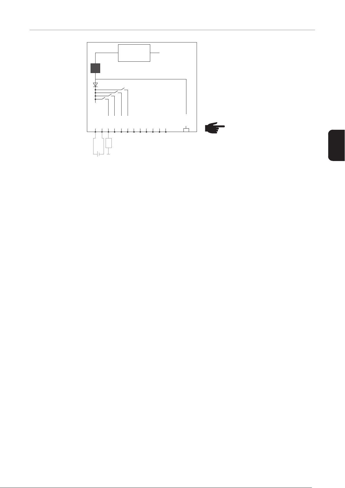
Σχηματικό διάγραμμα σύνδεσης εισόδων/
εξόδων
10,7 V DC
(2) 300 mA
Uint / Uext
GND
I/O 0
(4)
(3)
+ -
10,7 - 24 V DC
I/O 1
I/O 2
(1)
I/O 3
I 4
I 5
I 6
230 V AC
I 7
I 8
I 9
Solar Net
IN
Τροφοδοσία μέσω της εμβυσματούμενης
κάρτας Fronius Datamanager:
(1) Τροφοδοτικό
(2) Περιορισμός ρεύματος
Τροφοδοσία μέσω εξωτερικού
τροφοδοτικού:
(3) Εξωτερικό τροφοδοτικό
(4) Φορτίο
ΥΠΟΔΕΙΞΗ! Στην περίπτωση
τροφοδοσίας μέσω εξωτερικού
τροφοδοτικού, το εξωτερικό τροφοδοτικό πρέπει να είναι γαλβανικά απομονωμένο.
EL
65
Page 68

Καλωδίωση
Μέρη του Fronius
Solar Net
Καλωδίωση των
μερών του
Fronius Solar Net
Προϋποθέσεις
για το καλώδιο
δεδομένων Solar
Net
Οι μετατροπείς με Fronius Datamanager ή Fronius Com Card, τα εξαρτήματα DATCOM με
εξωτερικό περίβλημα ή άλλα εξαρτήματα DATCOM θα ονομάζονται εφεξής μέρη του
Fronius Solar Net.
Η σύνδεση δεδομένων των μερών του Fronius Solar Net πραγματοποιείται μέσω σύνδεσης 1:1 με 8-πολικά καλώδια δεδομένων και βύσματα RJ-45.
Το συνολικό μήκος αγωγών σε ένα Fronius Solar Net Ring επιτρέπεται να είναι 1000 m
κατά μέγιστο.
Για την καλωδίωση των μερών του Fronius Solar Net επιτρέπεται η χρήση αποκλειστικά
θωρακισμένων καλωδίων CAT5 (νέα) και CAT5e (παλιά) κατά τα πρότυπα ISO 11801 και
EN50173.
ΣΗΜΑΝΤΙΚΟ! Δεν επιτρέπεται η χρήση καλωδίων U/UTP κατά ISO/IEC-11801!
Επιτρεπόμενα καλώδια:
- S/STP
- F/STP
- S/FTP
- F/FTP
- SF/FTP
- S/UTP
- F/UTP
- U/FTP
- U/STP
Εδώ, η θωράκιση πρέπει να πρεσαριστεί σε ένα θωρακισμένο βύσμα εγκεκριμένο για
CAT5.
Επειδή οι αγωγοί στα καλώδια Ethernet είναι συνεστραμμένοι, προσέξτε τη σωστή κατανομή των συνεστραμμένων ζευγών αγωγών σύμφωνα με την καλωδίωση κατά το πρότυπο TIA/EIA-568B:
66
Page 69
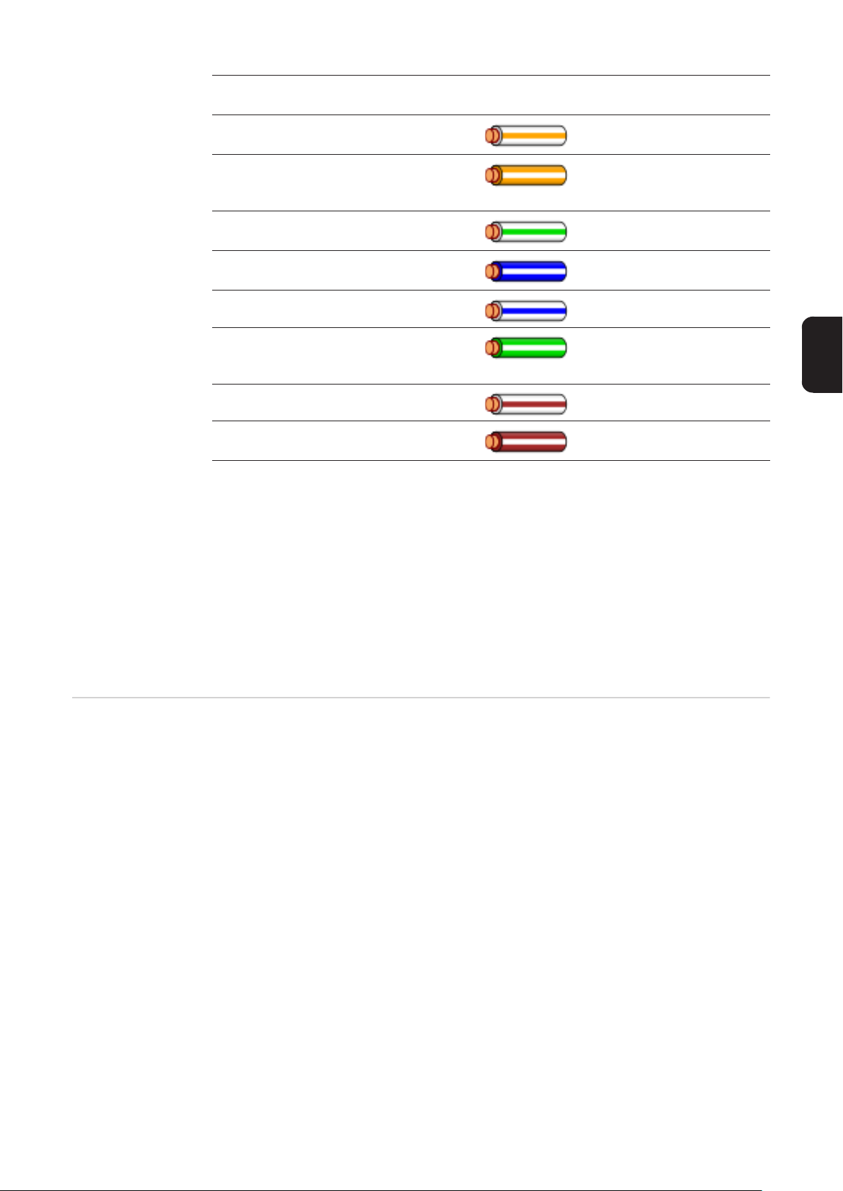
Επαφή Fronius Solar Net Αρ. ζεύ-
Χρώμα
γους
1 +12 V 3
λευκή / πορτοκαλί διαγράμμιση
πορτοκαλί / λευκή διαγράμ-
2 GND 3
μιση
ή πορτοκαλί
3 TX+ IN, RX+ OUT 2
4 RX+ IN, TX+ OUT 1
λευκή / πράσινη διαγράμμιση
μπλε / λευκή διαγράμμιση
ή μπλε
5 RX- IN, TX- OUT 1 λευκή / μπλε διαγράμμιση
πράσινη / λευκή διαγράμμι-
6 TX- IN, RX- OUT 2
ση
ή πράσινο
7 GND 4 λευκή / καφέ διαγράμμιση
EL
Έτοιμα καλώδια
δεδομένων
8 +12 V 4
Καλωδίωση κατά TIA/EIA-568B
καφέ / λευκή διαγράμμιση
ή καφέ
- Προσέξτε τη σωστή αντιστοίχιση των αγωγών.
- Στην περίπτωση αυτόνομης γείωσης (π.χ. σε κατανεμητές) προσέξτε η θωράκιση να
είναι γειωμένη μόνο στη μία πλευρά του καλωδίου.
Γενικώς, τηρείτε τα παρακάτω πρότυπα για τη δομημένη καλωδίωση:
- για την Ευρώπη, το πρότυπο EN50173-1
- διεθνώς, το πρότυπο ISO/IEC 11801:2002.
- για τη Βόρεια Αμερική, το πρότυπο TIA/EIA 568
Ισχύουν οι κανόνες εφαρμογής για χάλκινα καλώδια.
Στη Fronius διατίθενται τα παρακάτω έτοιμα καλώδια δεδομένων:
- Καλώδιο CAT5 1 m ... 43,0004,2435
- Καλώδιο CAT5 20 m ... 43,0004,2434
- Καλώδιο CAT5 60 m ... 43,0004,2436
Τα αναφερόμενα καλώδια είναι 8-πολικά καλώδια δικτύου LAN 1:1, θωρακισμένα και συνεστραμμένα, συμπεριλαμβανομένων των βυσμάτων RJ45.
ΣΗΜΑΝΤΙΚΟ! Τα καλώδια δεδομένων δεν είναι ανθεκτικά στην υπεριώδη ακτινοβολία. Σε
περίπτωση τοποθέτησης σε εξωτερικούς χώρους, προστατέψτε τα καλώδια δεδομένων
από την ηλιακή ακτινοβολία.
67
Page 70
Τοποθέτηση του Fronius Datamanager στον μετατροπέα
Γενικά Εφόσον η plug-in κάρτα του Fronius Datamanager δεν περιλαμβάνεται στο βασικό εξοπλι-
σμό του μετατροπέα, η τοποθέτησή της στο μετατροπέα πρέπει να πραγματοποιηθεί σύμφωνα με τις οδηγίες χειρισμού και εγκατάστασης του αντίστοιχου μετατροπέα. Λαμβάνετε
υπόψη σας τις υποδείξεις ασφαλείας και τις προειδοποιητικές υποδείξεις στις οδηγίες χειρισμού των μετατροπέων.
ΣΗΜΑΝΤΙΚΟ! Προτού τοποθετήσετε την plug-in κάρτα Fronius Datamanager, αφαιρέστε
την κάρτα Fronius Power Control Card ή Fronius Modbus Card, εφόσον υπάρχει!
Ασφάλεια
ΠΡΟΕΙΔΟΠΟΙΗΣΗ! Κίνδυνος θανάτου από ηλεκτροπληξία. Κίνδυνος λόγω τά-
σης δικτύου και τάσης DC των φ/β πλαισίων.
- Η πρόσβαση στην περιοχή σύνδεσης επιτρέπεται μόνο σε ηλεκτρολόγους με
σχετική επαγγελματική άδεια.
- Η αποσύνδεση της ξεχωριστής περιοχής των μονάδων ισχύος από την περιοχή σύνδεσης επιτρέπεται μόνο σε κατάσταση εκτός τάσης.
- Η πρόσβαση στην ξεχωριστή περιοχή των μονάδων ισχύος επιτρέπεται
μόνο σε εκπαιδευμένο προσωπικό σέρβις της Fronius.
Πριν από την εκτέλεση οποιασδήποτε εργασίας σύνδεσης, μεριμνήστε ώστε η
πλευρά AC και DC πριν το μετατροπέα να μην έχει τάση, π.χ.:
- διακόψτε την τάση του αυτόματου ασφαλειοδιακόπτη AC για το μετατροπέα
- καλύψτε τα φ/β πλαίσια
Τηρείτε τους 5 κανόνες ασφαλείας.
ΠΡΟΕΙΔΟΠΟΙΗΣΗ! Κίνδυνος θανάτου από ηλεκτροπληξία. Κίνδυνος από την
παραμένουσα τάση των πυκνωτών.
Περιμένετε να ολοκληρωθεί ο χρόνος εκφόρτισης των πυκνωτών.
ΥΠΟΔΕΙΞΗ! Κατά τη χρήση εμβυσματούμενων καρτών τηρείτε τις γενικές προδιαγραφές ηλεκτροστατικής εκφόρτισης.
68
Page 71
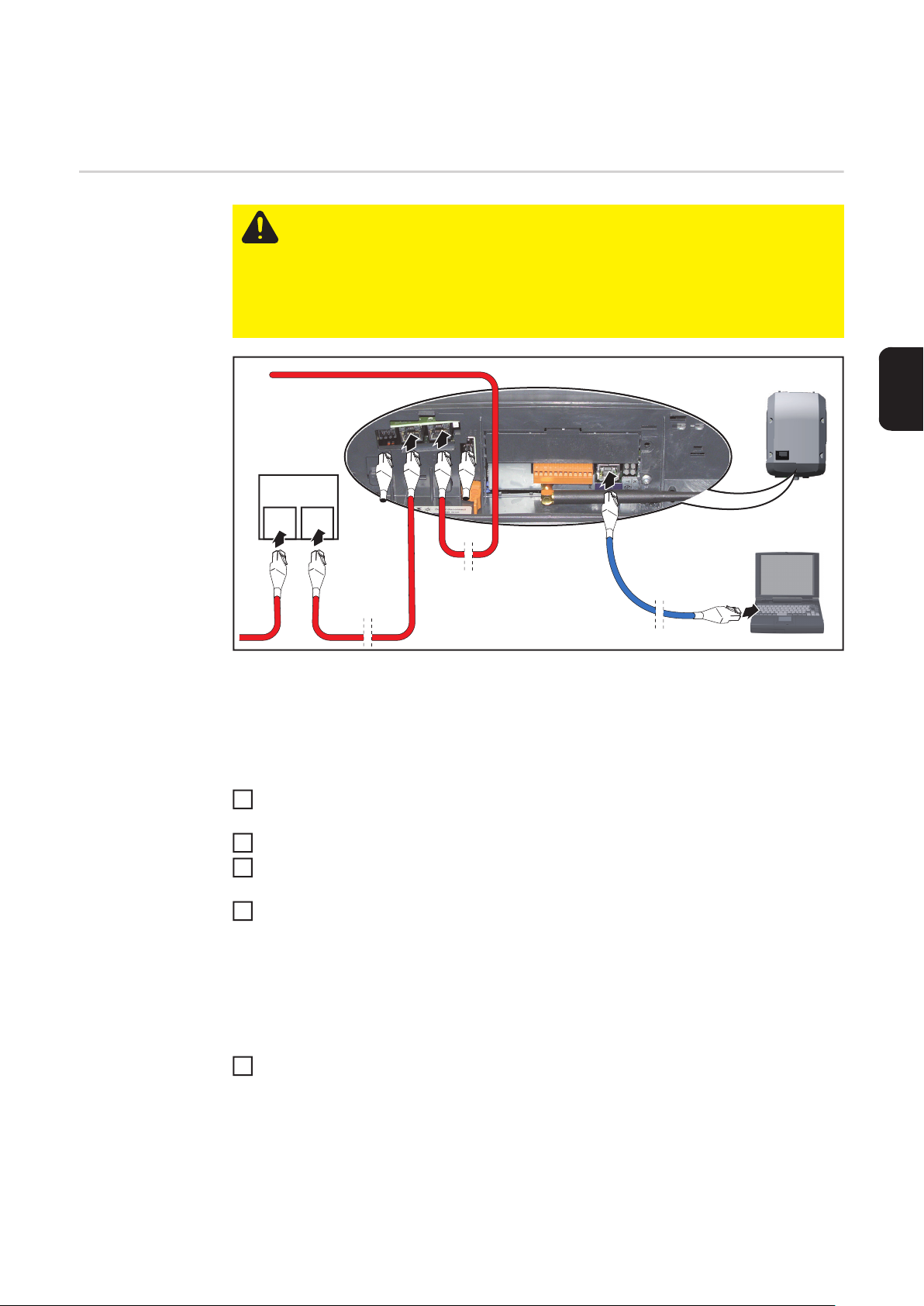
Εγκατάσταση του Fronius Datamanager στο Fronius
Solar Net
Εγκατάσταση μετατροπέα με
Fronius
Datamanager στο
Fronius Solar Net
IN
DATCOM
IN OUT
5
ΠΡΟΣΟΧΗ! Κίνδυνος σοβαρών υλικών ζημιών στα εξαρτήματα DATCOM ή στον
σταθερό / φορητό υπολογιστή εξαιτίας εσφαλμένης σύνδεσης καλωδίου Ethernet
ή Solar Net στο Fronius Datamanager.
- Συνδέστε το καλώδιο Ethernet αποκλειστικά στη σύνδεση LAN (μπλε χρωματική σήμανση).
- Συνδέστε τα καλώδια Solar Net στις συνδέσεις Solar Net IN και Solar Net
OUT του μετατροπέα
6
3
**
4
****
1
2
EL
* Τερματικά βύσματα, όταν συνδέεται μόνο ένας μετατροπέας με Fronius
Datamanager με έναν υπολογιστή ή όταν στη σύνδεση Solar Net δεν ακολουθεί άλ-
λος συνδρομητής Solar Net
** Καλώδιο Solar Net, όταν ένας μετατροπέας με Fronius Datamanager συνδέεται με
υπολογιστή και άλλα εξαρτήματα DATCOM
Τοποθετήστε το καλώδιο Ethernet στο μετατροπέα όπως ένα καλώδιο επικοινωνίας
1
δεδομένων, σύμφωνα με τις οδηγίες χειρισμού του μετατροπέα.
Συνδέστε το καλώδιο Ethernet στη σύνδεση LAN.
2
Συνδέστε το καλώδιο Ethernet στον σταθερό / φορητό υπολογιστή ή σε κατάλληλη
3
σύνδεση δικτύου.
Εάν μόνο ένας μετατροπέας με Fronius Datamanager συνδέεται με υπολογιστή:
4
Συνδέστε το τερματικό βύσμα στις συνδέσεις Solar Net IN και Solar Net OUT.
Εάν εκτός από το μετατροπέα με Fronius Datamanager ακολουθούν και άλλα εξαρτήματα DATCOM στο δίκτυο:
Συνδέστε το καλώδιο Solar Net στις συνδέσεις Solar Net IN και Solar Net OUT του μετατροπέα.
Καλωδιώστε και τα υπόλοιπα εξαρτήματα DATKOM μεταξύ τους.
5
ΣΗΜΑΝΤΙΚΟ! Σε κάθε ελεύθερη σύνδεση Solar Net του τελευταίου εξαρτήματος
DATCOM πρέπει να τοποθετηθεί ένα τερματικό βύσμα.
69
Page 72
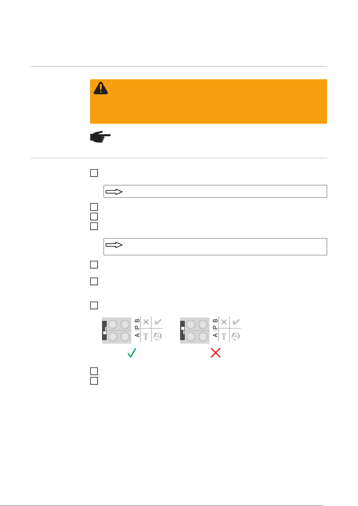
Εγκατάσταση του Fronius Datamanager - Επισκόπηση
Ασφάλεια
Πρώτη θέση σε
λειτουργία
ΠΡΟΕΙΔΟΠΟΙΗΣΗ! Ο λανθασμένος χειρισμός μπορεί να προκαλέσει σοβαρές
σωματικές βλάβες και υλικές ζημιές. Χρησιμοποιήστε τις περιγραφόμενες λειτουργίες μόνο εφόσον έχετε μελετήσει και κατανοήσει πλήρως:
- τις παρούσες οδηγίες χειρισμού
- τις οδηγίες χειρισμού όλων των εξαρτημάτων του συστήματος, δίνοντας έμφαση στις προδιαγραφές ασφάλειας
ΥΠΟΔΕΙΞΗ! Η εγκατάσταση του Fronius Datamanager προϋποθέτει γνώσεις τεχνολογίας δικτύων.
Τοποθετήστε το Fronius Datamanager στο μετατροπέα
1
βλ. ενότητα «Τοποθέτηση του Fronius Datamanager στο μετατροπέα»
Συνδέστε το μπλε καλώδιο Ethernet στο Fronius Datamanager (σύνδεση LAN)
2
Συνδέστε το τερματικό βύσμα στο Fronius Datamanager (σύνδεση Solar Net IN)
3
Συνδέστε το μπλε καλώδιο Ethernet στον σταθερό / φορητό υπολογιστή
4
βλ. ενότητα «Εγκατάσταση του Fronius Datamanager στο Fronius Solar
Net»
Απενεργοποιήστε το WLAN στον σταθερό / φορητό υπολογιστή (για να αποφύγετε τις
5
διενέξεις δικτύου)
Στον σταθερό / φορητό υπολογιστή προσαρμόστε τις ρυθμίσεις δικτύου για το Fronius
6
Datamanager:
Η επιλογή «Αυτόματη λήψη διεύθυνσης IP (DHCP)» πρέπει να είναι ενεργοποιημένη
Ρυθμίστε το διακόπτη IP του Fronius Datamanager στη θέση - A -
7
Κλείστε το μετατροπέα και ενεργοποιήστε τον
8
Μετά από περ. 1 λεπτό ανοίξτε το πρόγραμμα περιήγησης στον σταθερό / φορητό
9
υπολογιστή και πληκτρολογήστε την παρακάτω διεύθυνση (ο διακομιστής δικτύου λειτουργεί με Internet Explorer έκδοσης 9 ή νεότερη, Chrome και Firefox):
http://169.254.0.180
Εμφανίζεται η αρχική σελίδα του Βοηθού θέσης σε λειτουργία.
70
Page 73
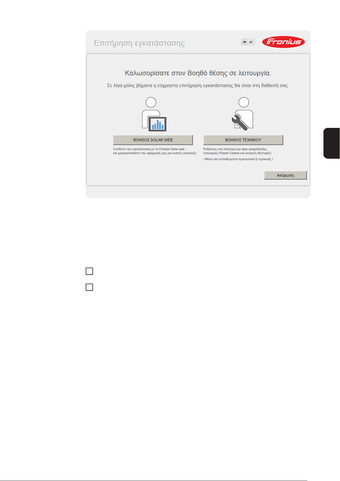
Ο Βοηθός τεχνικού προορίζεται για τον εγκαταστάτη και περιλαμβάνει ρυθμίσεις βασισμένες σε ειδικά πρότυπα.
Αν εκτελέσετε τον Βοηθό τεχνικού, σημειώστε οπωσδήποτε τον εκχωρημένο κωδικό πρόσβασης σέρβις. Αυτός ο κωδικός πρόσβασης σέρβις είναι απαραίτητος για τη ρύθμιση των
στοιχείων μενού «Editor παρόχου ενέργειας» και «Μετρητές».
Αν δεν εκτελέσετε τον Βοηθό τεχνικού, δεν θα οριστεί καμία προεπιλογή μείωσης ισχύος.
Η εκτέλεση του Βοηθού Solar Web είναι υποχρεωτική!
Αν χρειάζεται, εκτελέστε τον Βοηθό τεχνικού και ακολουθήστε τις οδηγίες.
6
Εκτελέστε τον Βοηθό Solar Web και ακολουθήστε τις οδηγίες.
7
Εμφανίζεται η αρχική σελίδα του Fronius Solar Web
ή
εμφανίζεται η ιστοσελίδα του Fronius Datamanager.
EL
ΣΗΜΑΝΤΙΚΟ! Για τη δημιουργία σύνδεσης στο Fronius Datamanager πρέπει η εκάστοτε
τελική συσκευή (π.χ. φορητός υπολογιστής, Tablet κτλ.) να είναι ρυθμισμένη ως εξής:
- Η επιλογή «Αυτόματη λήψη διεύθυνσης IP (DHCP)» πρέπει να είναι ενεργοποιημένη
71
Page 74

Τεχνικά χαρακτηριστικά
Τεχνικά χαρακτηριστικά
Χωρητικότητα μνήμης 16 Mbyte
Τάση τροφοδοσίας 230 V AC
Κατανάλωση ενέργειας τυπ. 1,4 W (χωρίς WLAN)
τυπ. 2,2 W (με WLAN)
Διαστάσεις 132 x 103 x 22 mm
5,2 x 4,1 x 0,9"
Ethernet (LAN) RJ 45, 100 Mbit
WLAN IEEE 802.11b/g Client
RS 485 (Fronius Solar Net) RJ 45
Θερμοκρασία περιβάλλοντος -20 - +65 ° C
-4 - +149 °F
Ισχύς Solar Net περ. 3 W
μέγ. 3 εξαρτήματα DATCOM *
Προδιαγραφές σύνδεσης I/O
Στάθμη τάσης ψηφιακών εισόδων low = ελάχ. 0 V - μέγ. 1,8 V
high = ελάχ. 3 V - μέγ. 30 V
Ρεύμα εισόδου ψηφιακών εισόδων ανάλογα με την τάση εισόδου,
αντίσταση εισόδου = 46 kOhm
Δυνατότητα μεταγωγής ψηφιακών εξόδων
σε περίπτωση τροφοδοσίας μέσω της εμβυσματούμενης κάρτας Fronius Datamanager
Δυνατότητα μεταγωγής ψηφιακών εξόδων
σε περίπτωση τροφοδοσίας μέσω εξωτερικού τροφοδοτικού με ελάχ. 10,7 - μέγ. 24 V
DC
Μέγ. μεταγόμενη ενέργεια ψηφιακών εξόδων
* Όταν η τροφοδοσία ρεύματος είναι επαρκής στο Fronius Solar Net, ανάβει σε κάθε
εξάρτημα DATCOM η πράσινη LED.
Εάν η πράσινη LED δεν ανάβει, συνδέστε στη σύνδεση συσκευής δικτύου 12 V του
εξαρτήματος DATCOM τη συσκευή δικτύου που διατίθεται από τη Fronius.
Εάν χρειάζεται, ελέγξτε τις συνδέσεις καλωδίου και τις εμβυσματούμενες συνδέσεις.
Συνολικά και για τις 4 ψηφιακές εξόδους
(μείον τα άλλα μέρη του Solar Net)
(αναλόγως του εξωτερικού τροφοδοτικού)
3,2 W, 10,7 V
1 A, 10,7 - 24 V DC
ανά ψηφιακή έξοδο
76 mJ
(ανά έξοδο)
72
Page 75

EL
73
Page 76

Fronius Worldwide - www.fronius.com/addresses
Fronius International GmbH
4600 Wels, Froniusplatz 1, Austria
E-Mail: pv-sales@fronius.com
http://www.fronius.com
Under http://www.fronius.com/addresses you will find all addresses of our sales branches and partner firms!
Fronius USA LLC Solar Electronics Division
6797 Fronius Drive, Portage, IN 46368
E-Mail: pv-us@fronius.com
http://www.fronius-usa.com
 Loading...