


Operating
Instructions
Fronius Datamanager 2.0
Fronius Datamanager Box 2.0
EN-US
Operating instructions
42,0426,0191,EA 023-13042023


Table of contents
General information 7
General 9
General 9
Available versions of the Fronius Datamanager 2.0 9
Applicable DATCOM Components 9
Prerequisites for operation 10
Inverter software required 10
Notes regarding radio certification 11
Scope of Supply 12
Using the Sticker Labels 13
Configuration Examples 13
Calculating the data volume 16
General 16
Calculating data volumes 16
General information for the network administrator 17
Requirements 17
General Firewall Settings 17
Sending Service Messages via a DSL Internet Connection 18
Using Fronius Solar.web and Sending Service Messages 18
Controls, connections and indicators 19
Safety 19
Controls, connections, and indicators 20
Schematic Connection of I/Os 24
Technical data 27
Technical data 27
WLAN 28
EN-US
Installing Fronius Datamanager 2.0 29
Inserting Fronius Datamanager 2.0 into an Inverter 31
General 31
Safety 31
Fronius Datamanager 2.0 plug-in positions 31
Installing and connecting WLAN antennas 33
General 33
Fronius IG, Fronius IG Plus, Fronius IG Plus V, Fronius CL: Installing and Connecting Antennas
Fronius IG USA, Fronius IG Plus USA, Fronius IG Plus V USA: Installing and Connecting
Antennas
Installing Fronius Datamanager 2.0 in Fronius Solar Net 37
Safety 37
Installing Inverters with Fronius Datamanager 2.0 in Fronius Solar Net 37
Installing Fronius Datamanager Box 2.0 in Fronius Solar Net 38
Fronius Solar Net Cabling 40
Fronius Solar Net clients 40
Fronius Solar Net Client Cabling 40
Requirements for the Fronius Solar Net data cables 40
Preassembled data cables 41
Installing Fronius Datamanager 2.0 – Overview 42
Safety 42
Starting for the first time using the Fronius Solar.start app 42
Starting for the first time via a web browser 44
33
34
Establishing a Connection to Fronius Datamanager 2.0 49
Connecting to Fronius Datamanager 2.0 via a Web Browser 51
General 51
Requirements 51
3

Establishing a Connection to Fronius Datamanager 2.0 via a Web Browser 51
Connecting to Fronius Datamanager 2.0 via the Internet and Fronius Solar.web 52
General 52
Function Overview 52
Requirements 52
Accessing Data from Fronius Datamanager 2.0 via the Internet and Fronius Solar.web 52
Current Data, Services, and Settings on Fronius Datamanager 2.0 53
The Fronius Datamanager 2.0 Website 55
Fronius Datamanager 2.0 Website – Overview 55
Login 55
Reset password 56
The Settings menu 56
Other setting options 56
Current Data in Fronius Datamanager 2.0 58
Current Comparison View 58
System Overview 58
Inverter/Sensor View 58
Services – System Information 59
System information 59
Services – Network Diagnostics 60
Network diagnostics 60
Services – Firmware Update 61
General 61
Automatic update search 61
Manual update search 61
Firmware update via web 61
Firmware update via LAN 61
Services – Opening Wizards 63
Opening wizards 63
Settings – General 64
General 64
Settings – Passwords 65
General 65
Passwords 65
Settings – Network 66
Internet via WLAN 66
Internet via LAN 66
Local network via Access Point 66
Settings – Fronius Solar.web 68
Solar.web 68
Memory capacity 68
Calculating memory capacity 68
Calculation example 69
Settings - IO Mapping 70
General 70
AUS – Demand Response Modes (DRM) 70
IO control 71
Load management 71
Settings - load management 72
General 72
Load management 72
Settings – Push Service 73
Push Service 73
Modbus Settings 74
General 74
Additional information on the Modbus function 74
Data output via Modbus 74
Limiting control 76
Save or Reject Changes 76
Settings – Inverter 77
4

Inverter 77
Settings – Fronius Sensor Cards 78
Sensor Cards 78
Settings – Counter 79
General 79
Fronius Smart Meter 79
Connecting the Fronius Smart Meter to the Fronius Datamanager 2.0 80
S0 Inverter 80
Settings – DNO Editor 82
General 82
UC Editor – IO control 82
Connection example 83
UC Editor—AUS—Demand Response Modes (DRM) 84
UC Editor – dynamic power reduction 84
UC Editor – Control priorities 85
EN-US
5

6

General information
7

8

General
General The Fronius Datamanager 2.0 is a network-compatible datalogger which com-
bines the functionality of the Fronius Com Card, the Fronius Datalogger Web,
the Fronius Power Control Card, and the Fronius Modbus Card on one plug-in
card.
The Fronius Datamanager 2.0 website provides a quick overview of the photovoltaic system.
The website can be accessed with a web browser via a direct connection or on the
internet, if properly configured.
When connected to Fronius Solar.web, the real-time and archived data of a
photovoltaic system can be easily accessed via the internet or the Fronius Solar.web app. No difficult configuration is required. Data is sent automatically from
the Fronius Datamanager 2.0 to Fronius Solar.web. Fronius Solar.web is equipped
with an easy-to-configure system monitoring feature with an automatic alarm.
The alarm can be signaled via SMS or e-mail.
EN-US
Available versions of the
Fronius
Datamanager 2.0
Applicable DATCOM Components
The Fronius Datamanager 2.0 is available in the following versions:
Without Fronius Com Card function
-
(for Fronius Galvo Fronius Symo, and Fronius Primo inverters)
With Fronius Com Card function
-
(for Fronius IG, Fronius IG Plus, Fronius IG Plus V,
Fronius IG Plus A, Fronius CL, Fronius CL USA, Fronius IG 300–500 inverters)
In external housing with Fronius Solar Net IN and Fronius Solar Net OUT
-
connection sockets
(Fronius Datamanager Box 2.0, e.g., for inverters without plug-in card slots or
for photovoltaic systems with a separate Fronius Datamanager 2.0)
Provided that the inverter is not fitted as standard with the Fronius Datamanager
2.0, existing inverters can be upgraded with the Fronius Datamanager 2.0 plug-in
card.
The Fronius Datamanager 2.0 plug-in card installed in the inverter or the separate Fronius Datamanager Box 2.0 can be operated with the following DATCOM
components:
- up to 100 x Fronius inverters
(incl. the inverter in which Fronius Datamanager 2.0 is
installed)
- up to 10 x Fronius Sensor Card or Fronius Sensor Box
- up to 10 x Fronius Public Display Card or Fronius Public Display
Box
- up to 1 x Fronius Interface Card or Fronius Interface Box
- up to 200 x Fronius String Control
9

Prerequisites for
operation
In order to ensure flawless data exchange online, a suitable internet connection
is required:
For cabled internet solutions, Fronius recommends a download speed of at
-
least 512 kbit/s and an upload speed of
at least 256 kbit/s.
For solutions with mobile internet services, Fronius recommends a minimum
-
transmission standard of 3G with reliable signal strength.
These specifications do not provide an absolute guarantee of flawless operation.
High error rates in the transmission, reception fluctuations, or connection dropouts can have an adverse effect on Fronius Datamanager 2.0's online operation.
Fronius recommends on-site testing to ensure that the connections meet the
minimum requirements.
For operation with an antenna extension.
If you want to connect your inverter(s) to the internet using WLAN, we recommend the following approach:
Test your signal strength in the exact position where the inverter is to be in-
-
stalled and make sure the Datamanager 2.0 card is activated.
Connect to the WLAN network using a smartphone, laptop, or tablet, and
-
test the connection.
The free website "www.speedtest.net" can be used to check whether the connection meets our recommended download speed of at least 512 kbit/s and
an upload speed of 256 kbit/s.
Since the Fronius Datamanager 2.0 acts as a datalogger, no other datalogger may
be present in the Fronius Solar Net ring.
There must only be one Fronius Datamanager 2.0 for each Fronius Solar Net ring.
The Fronius Datamanager 2.0 must be in secondary mode if installed in Fronius
Galvo and Fronius Symo inverters.
The following DATCOM components must not be operated together with Fronius
Datamanager 2.0 in a Fronius Solar Net ring:
Fronius Power Control Card/Box
-
Fronius Modbus Card
-
Fronius Datalogger Web
-
Fronius Personal Display DL Box
-
Fronius Datalogger easy/pro
-
Fronius Datamanager
-
Fronius Datamanager 2.0 Box
-
To use the Fronius Datamanager 2.0
the plug-in card must be installed in an inverter,
-
or
there must be a Fronius Datamanager Box 2.0 in the Fronius Solar Net ring.
-
The Fronius Datamanager 2.0 plug-in card and the Fronius Com Card must not
be used together in one inverter.
Inverter software required
10
Fronius Datamanager 2.0 requires the following inverter software versions for its
operation:
required software version according to display
Inverter
Fronius IG 15–60 V2.9.4 or higher
(MainControl)

Inverter
required software version according to display
(MainControl)
Fronius IG 2000–
5100
Fronius IG 300–500 V3.6.4.0 or higher
Fronius IG Plus 35–
150
Fronius IG TL * -
Fronius CL V4.22.00 or higher
Fronius Agilo * -
Fronius Agilo Outdoor *
Fronius Agilo TL * -
Fronius Galvo -
Fronius Symo -
Fronius Symo Hybrid -
Fronius Primo -
Fronius Eco -
starting from series no 19153444
V4.22.00 or higher
-
EN-US
Notes regarding
radio certification
* Only in conjunction with Fronius Datamanager Box 2.0
The relevant inverter software version can be downloaded for free from our
homepage (http://www.fronius.com).
If you have any questions, please contact pv-support@fronius.com.
The Fronius Datamanager 2.0 plug-in card and Fronius Datamanager Box 2.0 are
equipped with a wireless module.
Wireless modules in the USA require FCC certification:
11

FCC
This device conforms to the limit values for a Class B digital device,
pursuant to Part 15 of the FCC regulations. These limits are designed to provide reasonable protection against harmful interference in a residential installation. This device generates and uses
high frequency energy and, if not used in accordance with the instructions, may interfere with radio communications. However,
there is no guarantee that interference will not occur in a particular
installation.
If this device does cause harmful interference to radio or television
reception, which can be determined by turning the device off and
on, the user is encouraged to try to correct the interference by one
or more of the following measures:
Reorient or relocate the receiving antenna.
-
Increase the distance between the device and the receiver.
-
Connect the device to a different circuit than the receiver.
-
Consult the dealer or an experienced radio/TV technician for
-
help.
FCC ID: PV7-WIBEAR11N-DF1
Industry Canada RSS
This device complies with Industry Canada license-exempt RSS
standards. Operation is subject to the following two conditions:
(1) this device is not permitted to cause harmful interference, and
(2) this device must accept any interference, including interference
that may cause undesired operation of the device.
IC ID: 7738A-WB11NDF1
Unless otherwise expressly permitted by the manufacturer, changes or modifications to the wireless module are not allowed and lead to a loss of the right of use
of the device by the user.
Scope of Supply Fronius Datamanager 2.0 plug-in card
1 x Fronius Datamanager 2.0 plug-in card
-
1 x Fronius Solar Net termination plug
-
1 x 16-pin plug
-
1 x FCC sticker label, three parts
-
Additional equipment depending on the inverter:
1 x antenna
-
1 x Fronius Solar Net termina-
-
tion plug
Fronius Galvo
Fronius Symo
Fronius Primo
12
1 x antenna
-
1 x 1 m RG58 antenna cable
-
1 x mounting bracket
-
1 x double-sided adhesive tape
-
1 x antenna
-
1 x 3 m RG58 antenna cable
-
1 x mounting bracket
-
1 x double-sided adhesive tape
-
Fronius IG
Fronius IG Plus
Fronius IG Plus V
Fronius IG 300 - 500
Fronius CL
Fronius CL - USA

1 x antenna
Fronius IG
Fronius IG Plus
Fronius IG Plus V
Fronius IG Plus A
Fronius Galvo
Fronius Symo
Fronius Primo
(1) (2) (3)
-
1 x 0.4 m RG58 antenna cable
-
1 x 3/4 in. screw joint
-
1 x 3/4 in. hex nut
-
1 x 3/4 in. seal
-
Fronius IG 2000 - 5100 - USA
Fronius IG Plus - USA
Fronius IG Plus V - USA
Fronius Datamanager Box 2.0
1 x Fronius Datamanager Box 2.0 with wall bracket
-
2 x Fronius Solar Net termination plugs
-
1 x 16-pin plug
-
1 x antenna
-
1 x 3 m RG58 antenna cable
-
1 x mounting bracket
-
1 x double-sided adhesive tape
-
2 x installation anchors + screws
-
1 x "DATCOM Cabling" leaflet
-
EN-US
Using the Sticker
Labels
IMPORTANT! If the three-part sticker label included in the scope of supply for
the Datamanager 2.0 has not already been affixed to the inverter at the factory,
this must be done now.
Position of the sticker label on the inverter:
For Fronius Galvo, Fronius Symo, and Fronius Primo inverters, the sticker label
information is located on the rating plate.
Configuration
Examples
Using the sticker labels:
(1) On the cardboard packaging of
the inverter or the Fronius
Datamanager 2.0
(2) On the Fronius Datamanager
2.0 plug-in card
(3) On the inverter
Linking Inverters with a Fronius Datamanager 2.0 Plug-in Card to a PC:
13
IN
(1)
(2)
(3)
(4)
WLAN
OUT
IN
IN
IN
OUT
OUT
OUT
IN
(1)
(6)
(4) (7)
(2)
(3)
(5) (8)
LAN / WLAN
(9)
(1) Inverter
(2) Fronius Datamanager 2.0
(3) Fronius Solar Net termination
plug
(4) PC/laptop
IMPORTANT!When linking an inverter with Fronius Datamanager 2.0 to a PC,
one Fronius Solar Net termination plug must be connected at each free IN or
OUT connection.
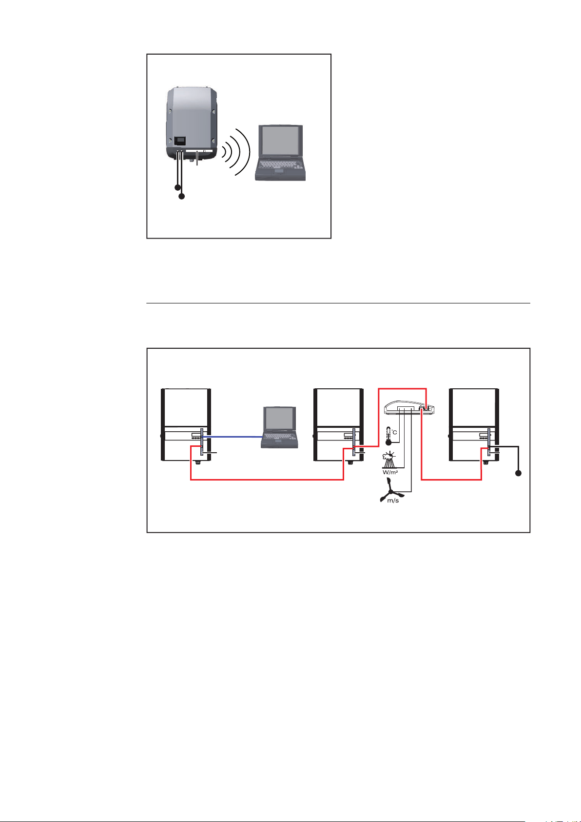
Linking Inverters with a Fronius Datamanager 2.0 Plug-in Card to Other Inverters, a Fronius Sensor Box, and a PC:
14
(1) Inverter with
(2) Fronius Datamanager 2.0
(3) PC/laptop
(4) Inverter with
(5) Fronius Com Card
(6) Fronius Sensor Box
(7) Inverter
(8) Fronius Com Card
(9) Fronius Solar Net termination
plug
When linking several DATCOM components to Fronius Datamanager 2.0:
Use the data cable to connect the IN connection socket of Fronius Datamanager
2.0 with the OUT connection socket of the next DATCOM component. A Fronius
Solar Net termination plug must be inserted into the empty IN connection socket of the last DATCOM component.
With the following inverters, the inverter with Fronius Datamanager 2.0 must always be connected either at the start or end of the data chain:
Fronius IG, Fronius IG Plus, Fronius IG Plus V, Fronius IG Plus A, Fronius CL,
Fronius CL USA and Fronius IG 300–500.

Linking Two Inverters with Fronius Com Card or Com Card Function to a
IP
B A
Fronius
Datamanager Box 2.0
IN
OUT
IN OUT
=
~
IN
OUT
=
~
WLAN
(1) (2)
Fronius
Solar.web App
(3)
(4)
(5)
(5)
Fronius Datamanager Box 2.0 and a Smartphone:
EN-US
(1) Inverter with Fronius Com
Card or Com Card function
(2) Inverter with Fronius Com
Card or Com Card function
(3) Fronius Datamanager Box 2.0
When linking several DATCOM components with a Fronius Datamanager Box 2.0,
each of the DATCOM components must be cabled from the IN connection socket to the OUT connection socket of the next DATCOM component.
Fronius Solar Net termination plugs must be inserted into empty IN or OUT connection sockets of the last DATCOM components.
(4) Smartphone with Fronius Sol-
ar.web App
(5) Fronius Solar Net termination
plug
15

Calculating the data volume
General When operating Fronius Datamanager 2.0, data are generated and need to be
transmitted via the internet.
In order to select a suitable internet connection, it is necessary to calculate the
data volume.
Calculating data
volumes
The following information is used to calculate the data volume per month when
operating the Fronius Datamanager 2.0.
Up to firmware
version 3.17
Hourly upload
Total 8 MB 350 MB
+ for each additional Fronius inverter 5 MB
+ for each additional Fronius Smart Meter 7 MB
Up to firmware
Daily/weekly upload
(without night mode)
Total 307 kB 350 MB
+ for each additional Fronius inverter 520 kB
+ for each additional Fronius Smart Meter 769 kB
Daily/weekly upload
(with night mode active)
version 3.17
Up to firmware
version 3.17
From firmware
version 3.25.2
upwards
From firmware
version 3.25.2
upwards
From firmware
version 3.25.2
upwards
Total 100 kB 350 MB
+ for each additional Fronius inverter 520 kB
+ for each additional Fronius Smart Meter 769 kB
Calculation of memory sectors per day according to chapter "Calculating
memory capacity" on page 68.
The data volume may increase due to the following factors:
Disconnections
-
Restarting the inverter
-
Firmware updates
-
Remote control (VPP, Cloud Control)
-
Fault diagnosis by technical support
-
Remote system monitoring via Fronius Solar.web
-
IMPORTANT! Fronius recommends a flat rate to avoid costs for data volumes
that were not taken into account in the preliminary calculation.
16

General information for the network administrator
Requirements Configuring a network for Fronius Datamanager 2.0 requires knowledge of net-
work technology.
If Fronius Datamanager 2.0 is being integrated into an existing network, the
Fronius Datamanager 2.0 address must be adapted to the network.
Example: network address range = 192.168.1.x, subnet mask = 255.255.255.0
An IP address between 192.168.1.1 and 192.168.1.254 must be assigned to
-
Fronius Datamanager 2.0.
The IP address selected may not be already assigned in the network.
-
The subnet mask must correspond to the existing network (e.g.,
-
255.255.255.0).
If Fronius Datamanager 2.0 will be sending service messages and/or data to
Fronius Solar.web, then a gateway address and a DNS server address must also
be entered. Fronius Datamanager 2.0 uses the gateway address to access the internet. The IP address of the DSL router can be used as a gateway address, for
example.
EN-US
General Firewall
Settings
IMPORTANT!
Fronius Datamanager 2.0 may not have the same IP address as the PC/
-
laptop!
Fronius Datamanager 2.0 cannot connect itself to the internet. A router
-
must be used for a DSL connection to the internet.
DSL routers mostly enable you to send data to the internet and, therefore, do not
normally have to be configured.
Server addresses for data transfer
If a firewall is used for outgoing connections, the following protocols, server addresses and ports must be allowed for successful data transfer:
Tcp fronius-se-iot-dm-1.azure.devices.net:8883
-
Tcp fronius-se-iot-dm-1.azure.devices.net:443
-
Tcp fronius-se-iot-dm-2.azure.devices.net:8883
-
Tcp fronius-se-iot-dm-2.azure.devices.net:443
-
Tcp fronius-se-iot-dm-1.telemetry.azure.devices.net:8883
-
Tcp fronius-se-iot-dm-1.telemetry.azure.devices.net:443
-
Tcp fronius-se-iot-dm-2.telemetry.azure.devices.net:8883
-
Tcp fronius-se-iot-dm-2.telemetry.azure.devices.net:443
-
Fdmp-solarweb.com:49049 (dm local port 54321)
-
Tcp http://www3.fronius.com:80
-
Tcp http://firmware-download.fronius.com:80
-
Tcp ftp://transfer.fronius.com:21
-
Tcp provisioning-lite.solarweb.com:443
-
Tcp froniusseiot.blob.core.windows.net:443
-
Upd/Tcp 0.time.fronius.com:123
-
If existing firewall rules block the connection to the Fronius system monitoring,
the following firewall rules must be added:
17

49049/UDP
80/TCP *)
Sending Service
Messages via a
DSL Internet
Connection
output
Sending service messages x -
Connecting to Datamanager via Fronius Solar.web
Connecting to Datamanager via Fronius Solar.access or Fronius Solar.Service
Accessing the Datamanager website - x
Configure the firewall so that the IP address of Fronius system monitoring can
send data to port 49049/UDP from “fdmp.solarweb.com”.
*) We recommend only allowing access to the web interface of the Fronius system monitoring from a secure network. If access via the internet is absolutely necessary (e.g. for service purposes during a limited time period), configure the network router so that requests for any external port are redirected to port 80/TCP.
Caution - this will make the inverter visible on the internet and more likely to be
subject to network attacks.
Normally, no additional router configuration is required for a regular DSL internet connection to access Fronius Solar.web and/or send service messages, because connections from the LAN to the internet are open.
x -
- x
input
Using Fronius
Solar.web and
Sending Service
Messages
However, an internet connection is required to use Fronius Solar.web and send
service messages.
Fronius Datamanager 2.0 cannot connect itself to the internet. A router must be
used for a DSL connection to the internet.
18

Controls, connections and indicators
EN-US
Safety
WARNING!
Danger due to incorrect operation.
This can result in severe personal injury and damage to property.
Do not use the functions described here until you have fully read and under-
▶
stood the Operating Instructions.
Do not use the functions described here until you have fully read and under-
▶
stood all of the Operating Instructions of the system components, especially
the safety rules.
19

Controls, con-
(5)
(1)
(2) (3)
(6)
(7)
(8)
(9)
(7)
(11)
(9)
(8)
(6)
(10)
Fronius Galvo
Fronius Symo
Fronius Primo
Fronius IG
Fronius IG Plus
Fronius IG Plus V
Fronius IG Plus A
Fronius CL
Fronius CL USA
Fronius IG 300 - 500
(1) (6)
(13)
(12)(11)(8) (9)(7)
(4)
(5)
(2)
(3)
(4)
nections, and indicators
No. Function
(1) IP switch
For changing the IP address:
20

No. Function
A Specified IP address and opening the WLAN access point
The Fronius Datamanager 2.0 uses fixed IP address 169.254.0.180
for a direct connection to a PC via LAN.
If the IP switch is set to position A, an access point for a direct
WLAN connection to the Fronius Datamanager 2.0 is also opened.
Access data for this access point:
Network name: FRONIUS_240.XXXXXX
Key: 12345678
The Fronius Datamanager 2.0 can be accessed:
via DNS name "http://datamanager"
-
via IP address 169.254.0.180 for the LAN interface
-
via IP address 192.168.250.181 for the WLAN access point
-
B Assigned IP address:
The Fronius Datamanager 2.0 works with an assigned IP address dynamic host configuration protocol (DHCP)
The IP address can be set on the Fronius Datamanager 2.0 website.
EN-US
In the case of the Fronius Datamanager 2.0 plug-in cards, the IP
switch is located underneath the LEDs and is separate in the case of
the Fronius Datamanager Box 2.0.
(2) WLAN LED
Flashes green: the Fronius Datamanager 2.0 is in service mode
-
(IP switch on the Fronius Datamanager 2.0 plug-in card is set to
position A or service mode was activated via the inverter display,
the WLAN access point is opened)
Lights up green: there is an existing WLAN connection
-
Flashes green/red alternately: the length of time for which the
-
WLAN access point is open after activation (1 hour) has been exceeded
Lights up red: there is no existing WLAN connection
-
Flashes red: faulty WLAN connection
-
Does not light up: the Fronius Datamanager 2.0 is in secondary
-
mode
(3) Solar.web LED connection
Lights up green: there is an existing connection to Fronius Sol-
-
ar.web
Lights up red: there is no existing connection to Fronius Sol-
-
ar.web, but one is required
Does not light up: no connection to Fronius Solar.web is re-
-
quired
21

No. Function
D-
-
-
1
3
5
7
9
D+
+
+
0
2
4
6
8
I IO RS485
(4) Power supply LED
Lights up green: sufficient power supply from Fronius Solar Net;
-
the Fronius Datamanager 2.0 is ready for operation.
Does not light up: no power or insufficient power supply from
-
Fronius Solar Net - an external power supply is required
or the
Fronius Datamanager 2.0 is in secondary mode
Flashes red: during an update process
-
IMPORTANT! Do not interrupt the power supply during an update process.
Lights up red: update process failed
-
(5) Connection LED
Lights up green: there is an active connection within Fronius
-
Solar Net
Lights up red: there is an interrupted connection within Fronius
-
Solar Net
Does not light up: the Fronius Datamanager 2.0 is in secondary
-
mode
(6) LAN Connection
Ethernet interface with blue color marking for connecting the Ethernet cable
(7) I/Os
Digital inputs and outputs
Modbus RTU 2-wire (RS485):
D- Modbus data D+ Modbus data +
22

No. Function
Int./ext. power supply
- GND
+ U
int/Uext
Output for internal voltage 10.8 V/12.8 V
or
Input for an external supply voltage
>12.8–24 V DC (+ 20%)
10.8 V:
Fronius IG, Fronius IG Plus, Fronius IG Plus V,
Fronius IG Plus A, Fronius CL, Fronius CL USA,
Fronius IG 300–500
12.8 V:
Fronius Galvo, Fronius Symo
Digital inputs: 0 - 3, 4 - 9
Voltage level: low = min. 0 V - max. 1.8 V; high = min. 3 V - max. 24
V DC (+ 20%)
Input currents: dependent on input voltage; input resistance =
46 kOhm
EN-US
Digital outputs: 0–3
Switching capacity when supplied by the Fronius Datamanager 2.0
plug-in card: 3.2 W, 10.8/12.8 V in total for all four digital outputs
10.8 V:
Fronius IG, Fronius IG Plus, Fronius IG Plus V, Fronius IG Plus A,
Fronius CL, Fronius CL USA, Fronius IG 300–500
12.8 V:
Fronius Galvo, Fronius Symo
Switching capacity when supplied by an external power supply with
min. 12.8 - max. 24 V DC (+ 20%), connected to Uint/Uext and GND:
1 A, 12.8 - 24 V DC (depending on the external power supply) per digital output
The connection to the I/Os is made via the supplied mating connector.
(8) Antenna plug
For screwing on the WLAN antenna or WLAN antenna extension
cable, depending on the inverter
23

No. Function
(9) Modbus termination switch (for Modbus RTU)
Internal bus termination with 120 ohm resistance (yes/no)
Switch in "on" position: Termination resistance of 120 Ohm active
Switch in "off" position: No termination resistance active
IMPORTANT! The termination resistance must be active for the first
and last device in an RS485 bus.
(10) Fronius Solar Net primary/secondary switch
For switching between primary and secondary mode within a Fronius
Solar Net ring
IMPORTANT! All LEDs on the Fronius Datamanager 2.0 plug-in card
are off in secondary mode.
(11) Fronius Solar Net IN connection socket
Fronius Solar Net input with red color marking for connecting to
other DATCOM components (e.g., inverters, sensor cards)
For the Fronius Datamanager 2.0 with Fronius Com Card function
only!
(for Fronius IG, Fronius IG Plus, Fronius IG Plus V, Fronius IG Plus
A, Fronius CL, Fronius CL USA, Fronius IG 300–500 inverters)
(12) Fronius Solar Net OUT connection socket
Fronius Solar Net output with red color marking for connecting other DATCOM components (e.g., inverters, sensor cards, etc.)
For the Fronius Datamanager Box 2.0 only!
(13) External power supply connection
For connecting an external power supply when the power supply
within Fronius Solar Net is insufficient (e.g., when too many DATCOM components are installed in Fronius Solar Net).
IMPORTANT! The external power supply unit for the Fronius
Datamanager Box 2.0 must be securely disconnected from components supplying grid voltage (SELV or Class 2 for USA/Canada).
The output power of the power supply unit may not exceed a max. of
15 VA/1.25 A.
If the power supply is sufficient, the Supply LED (4) lights up green.
For an external power supply, use only the Fronius power supply
unit!
For the Fronius Datamanager Box 2.0 only!
Schematic Connection of I/Os
24
Supply via the Fronius Datamanager 2.0 plug-in card:
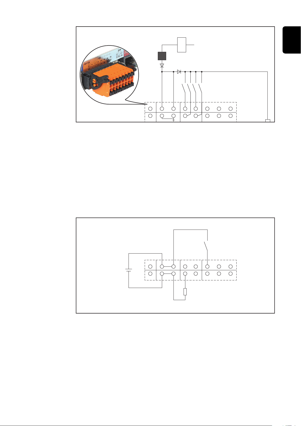
(1) 115 - 230 V AC
12 V DC
10,7 / 12,8 V DC
(2)
300 mA
(3)
D- - -
D+ + +
0 2
5 7893
4 6
1
(1) Power supply
D- - -
D+ + +
0 2
5 7893
4
6
1
(4)
(5)
(6)
10,7 / 12,8 - 24 V DC
(for Fronius Datamanager 2.0 with Fronius Com Card function only)
(2) Current limit
(3) Solar Net IN connection socket
115–230 V AC:
Fronius IG, Fronius IG Plus, Fronius IG Plus V, Fronius IG Plus A, Fronius CL,
Fronius CL USA, Fronius IG 300 - 500
12.8 V DC:
Fronius Galvo, Fronius Symo, Fronius Primo
EN-US
Supply via external power supply:
(4) External power supply
(5) Load
(6) Switch
When the supply is via an external power supply, the external power supply must
be galvanically isolated.
10.7 V DC:
Fronius IG, Fronius IG Plus, Fronius IG Plus V, Fronius IG Plus A, Fronius CL,
Fronius CL USA, Fronius IG 300 - 500
25

12.8 V DC:
Fronius Galvo, Fronius Symo, Fronius Primo
26

Technical data
EN-US
Technical data
Memory capacity up to 4096 days
Supply voltage
with Fronius Com Card function
without Fronius Com Card function
Energy consumption < 2 W
Dimensions
Plug-in card
Box
Degree of protection (box) IP 20
External power supply connection
(box)
Cable cross section for external power
supply connection (box)
Ethernet (LAN) RJ 45, 100 Mbit
WLAN IEEE 802.11b/g/n client
RS 422 (Fronius Solar Net) RJ 45
12 V DC, max. 1 A, Class 2
AWG 16–24 (USA/Canada)
115–230 V AC
12 V DC
132 x 103 x 22 mm
5.2 x 4.1 x 0.9 in.
190 x 114 x 53 mm
4.69 x 4.49 x 2.09 in.
0.13–1.5 mm²
Ambient temperature
Plug-in card
Box
Fronius Solar Net power approx. 3 W
max. 3 DATCOM components *
I/O connection specifications
Voltage level of digital inputs low = min. 0 V–max. 1.8 V
high = min. 3 V–max. 24 V (+ 20%)
Input currents of digital inputs depending on the input voltage;
input resistance = 46 kOhm
Switching capacity of digital outputs
when supplied by the Fronius
Datamanager 2.0 plug-in card
Fronius IG, Fronius IG Plus, Fronius
IG Plus V, Fronius IG Plus A, Fronius
CL, Fronius CL USA, Fronius IG 300–
500
-20–+65 °C
-4–+149°F
0–50°C
32–122 °F
3.2 W
10.8 V
27
 Loading...