


/ Perfect Charging / Perfect Welding / Solar Energy
Fronius Datalogger Web
Operating Instructions
System monitoring
EN-US
42,0426,0064,EA 006-05022019

2

Dear reader,
Introduction Thank you for the trust you have placed in our company and congratulations on buying this
high-quality Fronius product. These instructions will help you familiarize yourself with the
product. Reading the instructions carefully will enable you to learn about the many different
features your Fronius product has to offer. This will allow you to make full use of its advantages.
Please also note the safety rules to ensure greater safety when using the product. Careful
handling of the product will repay you with years of safe and reliable operation. These are
essential prerequisites for excellent results.
EN-US
3

4

Contents
General ...................................................................................................................................................... 7
General ................................................................................................................................................. 7
Applicable DATCOM components ........................................................................................................ 7
Prerequisites for operation.................................................................................................................... 7
Required Inverter Software ................................................................................................................... 7
Scope of supply .................................................................................................................................... 8
Controls, connections and indicators ......................................................................................................... 9
Safety.................................................................................................................................................... 9
Controls, Connections, and Indicators .................................................................................................. 9
Installing Fronius Datalogger Web............................................................................................................. 11
Safety.................................................................................................................................................... 11
Configuration Examples........................................................................................................................ 11
Preparation ........................................................................................................................................... 12
Installing 'Fronius Datalogger Web' ...................................................................................................... 12
Fronius Datalogger Web network configuration......................................................................................... 14
General ................................................................................................................................................. 14
Requirements........................................................................................................................................ 14
'Fronius Datalogger Web' network configuration .................................................................................. 14
Installing ‘Fronius Datalogger Web’ and going to the ‘Fronius Datalogger Web’ homepage................ 14
Enter the network data.......................................................................................................................... 15
Setting 'Fronius Datalogger Web' for the WLAN connection ................................................................ 18
Setting the IP address and connecting 'Fronius Datalogger Web' to the network ................................ 20
Network settings for PC/laptop .................................................................................................................. 22
General ................................................................................................................................................. 22
Network settings for PC/laptop ............................................................................................................. 22
Internet options for PC/laptop ............................................................................................................... 24
Connecting to 'Fronius Datalogger Web' via Internet browser................................................................... 26
General ................................................................................................................................................. 26
Requirements........................................................................................................................................ 26
Connecting to 'Fronius Datalogger Web' via Internet browser.............................................................. 26
For the network administrator ............................................................................................................... 26
Connecting to 'Fronius Datalogger Web' via 'Fronius Solar.access' .......................................................... 27
General ................................................................................................................................................. 27
Requirements ....................................................................................................................................... 27
Connecting to 'Fronius Datalogger Web' via 'Fronius Solar.access'..................................................... 27
For the network administrator ............................................................................................................... 28
Connecting to 'Fronius Datalogger Web' via the Internet and 'Fronius Solar.web' .................................... 29
General ................................................................................................................................................. 29
Function overview ................................................................................................................................. 29
Requirements ....................................................................................................................................... 29
Accessing data from 'Fronius Datalogger Web' via the Internet and 'Fronius Solar.web'..................... 30
For the network administrator ............................................................................................................... 30
Calculating the data volume....................................................................................................................... 31
General ................................................................................................................................................. 31
Firmware versions for calculating the data volume............................................................................... 31
Calculating the data volume.................................................................................................................. 31
Calculation examples............................................................................................................................ 32
General information for the network administrator..................................................................................... 34
General Firewall Settings...................................................................................................................... 34
Sending service messages via a DSL Internet connection................................................................... 34
Using 'Fronius Solar.web' and sending service messages ................................................................... 34
'Fronius Datalogger Web' views................................................................................................................. 35
Overview ............................................................................................................................................... 35
Current total view .................................................................................................................................. 35
Current comparison view ...................................................................................................................... 35
'Fronius Datalogger Web' settings ............................................................................................................. 37
Overview ............................................................................................................................................... 37
Accessing and editing selection options ............................................................................................... 37
Passwords ................................................................................................................................................. 38
General ................................................................................................................................................. 38
EN-US
5

Passwords ............................................................................................................................................ 38
User password ...................................................................................................................................... 38
Administrator Password ........................................................................................................................ 39
Forgot Your Password? ........................................................................................................................ 39
Time/Date .................................................................................................................................................. 40
General ................................................................................................................................................. 40
Time/Date ............................................................................................................................................. 40
Views ......................................................................................................................................................... 42
General ................................................................................................................................................. 42
Views .................................................................................................................................................... 42
'General' view........................................................................................................................................ 42
Inverter views........................................................................................................................................ 43
Sensor Card views................................................................................................................................ 43
Logging ...................................................................................................................................................... 45
General ................................................................................................................................................. 45
Logging ................................................................................................................................................. 45
Memory capacity................................................................................................................................... 45
Calculating memory capacity ................................................................................................................ 45
Calculation example.............................................................................................................................. 46
Overwriting data when memory is full ................................................................................................... 46
‘Delete Data’ button .............................................................................................................................. 46
Network...................................................................................................................................................... 48
General ................................................................................................................................................. 48
Network................................................................................................................................................. 48
Network diagnostics.............................................................................................................................. 48
Solar.web ................................................................................................................................................... 50
General ................................................................................................................................................. 50
Solar.web .............................................................................................................................................. 50
Daily data transmission to Solar.web.................................................................................................... 50
Hourly data transmission to Solar.web ................................................................................................. 50
Service messages...................................................................................................................................... 51
General ................................................................................................................................................. 51
Service messages................................................................................................................................. 51
System information .................................................................................................................................... 54
General ................................................................................................................................................ 54
System information ............................................................................................................................... 54
Firmware update ........................................................................................................................................ 55
General ................................................................................................................................................. 55
Automatic update search ...................................................................................................................... 55
Manual update search .......................................................................................................................... 55
Firmware Update via Web .................................................................................................................... 56
Firmware Update via LAN..................................................................................................................... 57
Technical Data ........................................................................................................................................... 58
Technical data....................................................................................................................................... 58
.............................................................................................................................................................. 58
6

General
General The 'Fronius Datalogger Web' is a network-compatible Datalogger. The 'Fronius Datalog-
ger Web' website provides a quick overview of the PV system.
The website can be accessed via a direct connection from the Intranet or with the proper
configuration via the Internet.
The 'Fronius Datalogger Web' is equipped with an easy-to-configure system monitoring
feature with an automatic alarm. The alarm can be signaled via SMS, e-mail, fax, relay contact or buzzer.
When connected to 'Fronius Solar.access,' realtime PV system data as well as archived
data can be saved to a PC and analyzed. You can also make settings to all devices in 'Fronius Solar Net.'
When connected to 'Fronius Solar.web,' realtime PV system data as well as archived data
can be easily accessed via the Internet - no difficult configuration required. Data is sent automatically from 'Fronius Datalogger Web' to 'Fronius Solar.web.'
EN-US
Applicable DATCOM components
Prerequisites for
operation
'Fronius Datalogger Web' can be used with the following DATCOM components:
- Up to 100 x ‘Fronius IG Plus,’ ‘Fronius IG’ or ‘Fronius CL’ inverters
- Up to 10 x 'Fronius Sensor Cards' or 'Fronius Sensor Boxes'
- Up to 10 x 'Fronius Public Display Cards' or 'Fronius Public Display Boxes'
- Up to 1 x 'Fronius Interface Card' or 'Fronius Interface Box'
- Up to 200 x 'Fronius String Controls'
The inverter requires a 'Fronius Com Card' in order to operate 'Fronius Datalogger Web.'
For a proper function of the ‘Fronius Datalogger Web‘ an appropriate Internet connection
is required:
- For cable-bound internet solutions Fronius recommends a download speed. of
min. 512 kBit/s and an upload speed of min. 256 kBit/s.
- For solutions with mobile internet services Fronius recommends min. 3G transmission
standard with a reliable signal strength.
This information does not constitute an absolute guarantee of proper operation.
High error rates in the transmission, reception fluctuations or transmission interruptions
can affect the online operation of the 'Fronius Datalogger Web' in a negative way.
Fronius recommends testing connections with minimum requirements on site.
Required Inverter
Software
The correct display of daily energy using Fronius Datalogger Web requires the following
inverter software versions:
Inverter Required software version according to display
(MainControl)
Fronius IG 15 - 60 V2.9.4 or higher
Fronius IG 2000 - 5100 starting from series no. 19153444
7

Inverter Required software version according to display
(MainControl)
Fronius IG 300 - 500 V3.6.4.0 or higher
Fronius IG Plus 35 - 150 V4.22.00 or higher
The respective inverter software version can be downloaded for free from our homepage
(http://www.fronius.com).
Please use a Fronius Update Card to update inverter software.
If you have any questions, please contact pv-support@fronius.com.
Scope of supply - 1 x 'Fronius Datalogger Web' Datalogger with wall mounting device
- 1 x 'Safety' leaflet
- 1 x 'Quick Installation' leaflet
- 1 x Ethernet cable 5 m, blue
- 1 x Solar Net cable 2 m, red
- 2 x Terminating plugs
- 2 x Installation anchors + screws
- 1 x 'Fronius Solar.access' CD
- 1 x Relay plug
- 1 x Relay connector housing
- 1 x Sticker set
8

Controls, connections and indicators
EN-US
Safety
Controls, Connections, and Indicators
WARNING!
Operating the device incorrectly can cause serious injury and damage.
Do not use the functions described until you
► have completely read and understood these Operating Instructions,
► have completely read and understood all system component Operating Instructions,
especially the safety rules.
(1)
(2)
12VDC 1A
max. 42V AC/6A
US: Class 2 only
Class 2
Output
12VDC
Class 2
Input only
(9) (10)
(13)(12)(11)(8)(7)(6)(5)(4)(3)
No. Function
(1) Solar Web LED connection
- Lights up green: There is an existing connection to 'Fronius Solar.web'
- Lights up red: There is no connection to 'Fronius Solar.web', but one is required
- Does not light up: No connection to 'Fronius Solar.web' is required
(2) Supply LED
- Lights up green: Sufficient power is coming from 'Fronius Solar Net'; 'Fronius Datalogger Web' is operational
- Does not light up: No power or not enough power coming from 'Fronius Solar Net' - an external power source for 'Fronius Datalogger Web' is required
- Flashes red: During an update process
IMPORTANT! Do not interrupt the power supply during an update process.
- Lights up red: Update process failed
(3) Relay connection
Equipped as an NCC (normally closed contact) and NOC (normally open contact), switches when there is an error
(4) Connection LED
- Lights up green: There is an active connection within 'Fronius Solar Net'
- Lights up red: There is an interrupted connection within 'Fronius Solar Net'
(5) WLAN LED
- Lights up green: There is an existing network connection
- Lights up red: There is no existing network connection
- Does not light up: The 'WLAN stick' is not inserted
9

No. Function
(6) Alarm switch
to switch the alarm function on/off
Alarm off:
Alarm function, relay and buzzer deactivated
Alarm on:
Alarm function, relay and buzzer activated, when 'Alarm on' is selected, the
buzzer and relay are briefly activated as a test
(7) IP address switch
used to switch from an assigned IP address to a default IP address
'169.254.0.180' (only relevant to LAN)
Assigned IP:
'Fronius Datalogger Web' operates using an assigned IP address (factory setting 192.168.1.180). The IP address can be set on the 'Fronius Datalogger
Web' website
169.254.0.180:
'Fronius Datalogger Web' uses the fixed IP address 169.254.0.180;
the fixed IP address is to connect directly to a PC without having to configure
the PC first
(8) LAN Connection
Blue Ethernet interface, used to connect the Ethernet cable
(9) USB connection
USB interface for connecting the 'WLAN stick' or 'WLAN stick outdoor' options
(10) Power supply connection 12 V DC / 1 A, electronic fuse protection
for supplying power to external components (e.g., external routers)
(11) External power supply connection
for connecting an external power supply when the power supply within 'Fronius
Solar Net' is insufficient (e.g., if too many DATCOM components are installed
on 'Fronius Solar Net').
Important! The external power supply unit for the Fronius Datalogger Web
must be securely disconnected from components supplying grid voltage (SELV
or Class 2 for USA/Canada).
The output power of the power supply unit may not exceed max. 15 VA/1.25 A.
If the power supply is sufficient, the Supply LED (2) lights up green.
(12) Solar Net IN connection socket
Red 'Fronius Solar Net' input for connecting other DATCOM components (e.g.,
inverters, sensor cards, etc.)
(13) Fronius Solar Net OUT connection socket
Red 'Fronius Solar Net' output for connecting other DATCOM components
(e.g., inverters, sensor cards)
10

Installing Fronius Datalogger Web
EN-US
Safety
Configuration Examples
WARNING!
Operating the device incorrectly can cause serious injury and damage.
Do not use the functions described until you
► have completely read and understood these Operating Instructions,
► have completely read and understood all system component Operating Instructions,
especially the safety rules.
Installing the 'Fronius Datalogger Web' Datalogger requires knowledge of network technology.
'Fronius Datalogger Web' networks with an inverter and a PC:
CPInverter / LaptopFronius Datalogger Web
12VDC 1A
Class 2
12VDC
Output
Class 2
Input only
max. 42V AC/6A
US: Class 2 only
IN
OUT
IN
OUT
= terminating plug
= Fronius Com Card
'Fronius Datalogger Web' networks with several inverters, a 'Fronius Sensor Box' and a
PC:
3 retrevnI2 retrevnI1 retrevnI
OUT
IN
IN
OUT
PC / Laptop
Fronius
Datalogger Web
IN OUT
IN
Fronius
Sensor Box
IN
OUT
OUT
= terminating plug
= Fronius Com Card
When networking several DATCOM components, a terminating plug must be placed on
each free IN or OUT connection of a DATCOM component.
11

Preparation IMPORTANT Please follow the operating instructions for the inverter as well as the 'Fro-
nius IG DATCOM Detail' operating instructions.
Install 'Fronius Datalogger Web' in the
1
proper position using the screws and
installation anchors provided in the
scope of supply
Fronius
Com Card
Insert the red Solar Net cable into the
2
Solar Net output (OUT) of the 'Fronius
Com Card'
If the 'Fronius Com Card' is the last
IN
3
DATCOM component in the network:
Insert a terminating plug into the Solar
OUT
Net OUT connection
Installing 'Fronius
Datalogger Web'
CAUTION!
DATCOM components and/or the PC/laptop will be damaged if the Ethernet or Solar
Net cables are connected incorrectly.
► The Ethernet cable should only be inserted into the LAN connection (colored blue)
► The Solar Net cable should only be inserted into the Solar Net IN or Solar Net OUT
connections (colored red)
12VDC 1A
Class 2
12VDC
Output
Class 2
max. 42V AC/6A
US: Class 2 only
Input only
12
Fronius Com Card
Insert the red Solar Net cable into the Solar Net output (OUT) of the 'Fronius Com
1
Card'
If the 'Fronius Com Card' is the last DATCOM component in the network:
2
Insert a terminating plug into the Solar Net OUT connection
If there are additional DATCOM components in the network after the 'Fronius Datalogger Web':
Insert an additional Solar Net cable into the Solar Net OUT connection
Insert the blue Ethernet cable into the LAN connection
3

Insert the blue Ethernet cable into the PC/laptop or into a corresponding network con-
4
nection
EN-US
13

Fronius Datalogger Web network configuration
General The network configuration function patented by Fronius enables the 'Fronius Datalogger
Web' to:
- establish an easy connection between 'Fronius Datalogger Web' and the PC/laptop
- make settings
- display important system data
Requirements The network configuration of the 'Fronius Datalogger Web' Datalogger requires knowledge
of network technology.
If the 'Fronius Datalogger Web' is being integrated into an existing network, the 'Fronius
Datalogger Web' address must be adapted to the network.
Example: Network address range = 192.168.1.x, subnet mask = 255.255.255.0
- An IP address between 192.168.1.1 and 192.168.1.254 must be assigned to the 'Fronius Datalogger Web'.
- The IP address selected may not be already assigned in the network.
- The subnet mask must correspond to the existing network (e.g., 255.255.255.0).
'Fronius Datalogger Web' network
configuration
If the 'Fronius Datalogger Web' will be sending service messages and/or data to 'Fronius
Solar.web,' then a gateway address and a DNS server address must also be entered. 'Fronius Datalogger Web' uses the gateway address to access the Internet. The IP address of
the DSL router can be used as a gateway address, for example.
IMPORTANT!
- 'Fronius Datalogger Web' may not have the same IP address as the PC/laptop.
- 'Fronius Datalogger Web' cannot connect to the Internet by itself. A router must be
used for a DSL connection to the internet.
If the network connection uses WLAN, then one of the following options is required:
- 'WLAN stick' (41,0018,0070)
- 'WLAN stick outdoor' (41,0018,0071)
The Fronius Datalogger Web network configuration comprises the following steps:
- Installing ‘Fronius Datalogger Web’ and going to the ‘Fronius Datalogger Web’ homepage
- Entering network data
- Setting 'Fronius Datalogger Web' for the WLAN connection
- Setting the IP address and connecting 'Fronius Datalogger Web' to the network
Installing ‘Fronius Datalogger
Web’ and going to
the ‘Fronius Datalogger Web’
homepage
14
Only if you are using the WLAN network connection:
1
connect the ‘WLAN stick’ or ‘WLAN stick outdoor’ option to the USB port
Install 'Fronius Datalogger Web'
2

12VDC 1A
Class 2
12VDC
Output
Class 2
max. 42V AC/6A
US: Class 2 only
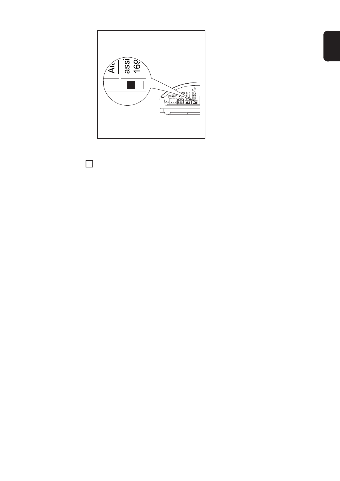
Set the IP address switch on the 'Fronius Datalogger Web' to '169.254.0.180'
3
Input only
EN-US
Enter the network
data
Wait approx. 1 minute until the 'Connectivity' icon appears in the PC/laptop taskbar.
4
Open the PC's/laptop's Internet browser (e.g., Microsoft Internet Explorer)
5
Enter 'http://169.254.0.180' in the address field
6
The 'Fronius Datalogger Web' website will appear.
The 'Fronius Datalogger Web' website will appear.
15

http://169.254.0.180
Click the 'Settings' menu item
1
The 'Settings' submenu is displayed.
Click 'Network'
2
The 'Network' submenu is displayed.
16

To determine whether a connection to the internet (e.g. to 'Fronius Solar.web') is re-
3
quired:
Click 'Internet connection'
The internet connection settings are displayed.
(1)
(2)
*)
*) WLAN can only be used when one of the two options 'WLAN stick' or 'WLAN stick
outdoor' is inserted in the 'Fronius Datalogger Web'.
EN-US
Select the type of internet connection (LAN or WLAN) (1)
4
Click on 'Save' (2)
5
After the changes have been loaded, the message 'Changes have been applied' appears.
Click on "OK"
6
The internet connection data is displayed
IMPORTANT! Depending on which internet connection you have selected, a gateway
and a DNS server must be entered for the relevant interface.
If, for example, a LAN internet connection was selected, a gateway and a DNS server
must be entered for the LAN interface.
Click on 'LAN' or 'WLAN' in the 'Network' submenu depending on the network connec-
7
tion interface you are using.
The settings for the LAN or WLAN interfaces are displayed.
17

(3)
(4)
Select either a static or dynamic IP address (3)
8
Obtain IP address statically (factory setting):
- The user enters a fixed (static) IP address for the 'Fronius Datalogger Web' and
also manually sets the subnet mask, gateway address and the DNS server address (from provider). Obtain IP address dynamically:
Obtain IP address dynamically:
- The 'Fronius Datalogger Web' obtains its IP address from a DHCP server (DHCP
= dynamic host configuration protocol).
- The DHCP server must be configured so that the 'Fronius Datalogger Web' is always assigned the same IP address. This means that the user always knows
which IP address can be used to access the 'Fronius Datalogger Web'.
- If the DHCP server supports the 'DNS dynamic updates' function, a name can be
entered for the 'Fronius Datalogger Web' in the 'Hostname' field. The connection
to the 'Fronius Datalogger Web' can then take place via the name instead of the
IP address.
Example: Hostname = sample system, Domain name = fronius.com
The 'Fronius Datalogger Web' can be accessed via the 'samplesystem.fronius.com' address
Click on 'Save' (4)
9
After the changes have been loaded, the message 'Changes have been applied' is
displayed
Click on 'OK'
10
The interface settings are displayed (LAN or WLAN).
Setting 'Fronius
Datalogger Web'
for the WLAN
connection
18
The following steps are only required if you decide to use the WLAN network connection
at a later date.
Click on 'WLAN' in the 'Network' submenu.
1
Enter the settings for the WLAN interface
2
Click on 'WLAN management' in the 'Network' submenu.
3
‘WLAN management’ is displayed with the available networks (1).

(1)
EN-US
(2)
Click on 'Update' (2) to update the networks
4
Select a suitable network by clicking on it
5
Click on 'Configure Network' (3).
6
'Configure Network' is displayed.
(3)
(5)
(4)
(6)
(7)
Enter the SSID network name (4)
7
Enter the encryption type (5):
8
none = no encryption
WEP = hexagonal encryption
WPA1/2 = encryption via pass phrase (8 - 63 ASCII characters)
Only if WEP or WPA1/2 encryption has been selected:
9
enter the corresponding pass phrase / key (6)
19

(4)
(5)
(6)
(7)
Click on 'Save' (7)
10
After the changes have been loaded, the message 'Changes have been applied' is
displayed.
Click on 'OK'
11
‘WLAN management’ is displayed.
Setting the IP address and connecting 'Fronius
Datalogger Web'
to the network
20
(9)(8)
You can use the arrow keys (8) and the ‘Save Order’ key (9) to change the sequence of
displayed networks.
Set the IP address switch on the 'Fronius Datalogger Web' to 'assigned IP'
1
The network settings are applied
Connect Fronius Datalogger Web to the relevant network via the LAN or WLAN con-
2
nection
EN-US
21

Network settings for PC/laptop
General The PC/laptop is also a member of the network and must also be assigned a unique net-
work address like the Datalogger.
If the PC is already integrated in the network, no further settings are required.
Network settings
for PC/laptop
Start / Control Panel / Network and In-
3
ternet Connections
Double-click on 'Network Connections'
4
Double-click on 'Local Area Connecti-
5
on'
Click on the 'Properties' button in the
4
'General' tab
22
Click on 'Internet Protocol (TCP/IP)'
2
Click on the 'Properties' button
3

The 'Internet Protocol (TCP/IP) Properties' window will appear.
EN-US
If a DHCP server is available in the network:
Select 'Obtain an IP address automatically'
7
If a DHCP server is not available in the network:
7a Select 'Use the following IP address'
7b Assign a unique IP address to the PC/laptop
Example: Network address range = 192.168.1.x, subnet mask = 255.255.255.0
- An IP address between 192.168.1.1 and 192.168.1.254 must be assigned to the
PC/laptop.
- The IP address selected may not be already assigned in the network.
- The subnet mask must correspond to the existing network (e.g., 255.255.255.0).
- The 'Default gateway' setting is not relevant to the 'Fronius Datalogger Web'
connection.
IMPORTANT The PC/laptop must not have the same IP address as the 'Fronius Datalogger Web.'
23

Activate 'Obtain DNS server address automatically'
8
Internet options
for PC/laptop
Open the Internet browser (e.g., Micro-
1
soft Internet Explorer)
Click on 'Tools'
2
Click on 'Internet Options'
3
Click on the 'Connections' tab
4
Click on the 'LAN settings' button at the
5
bottom
24
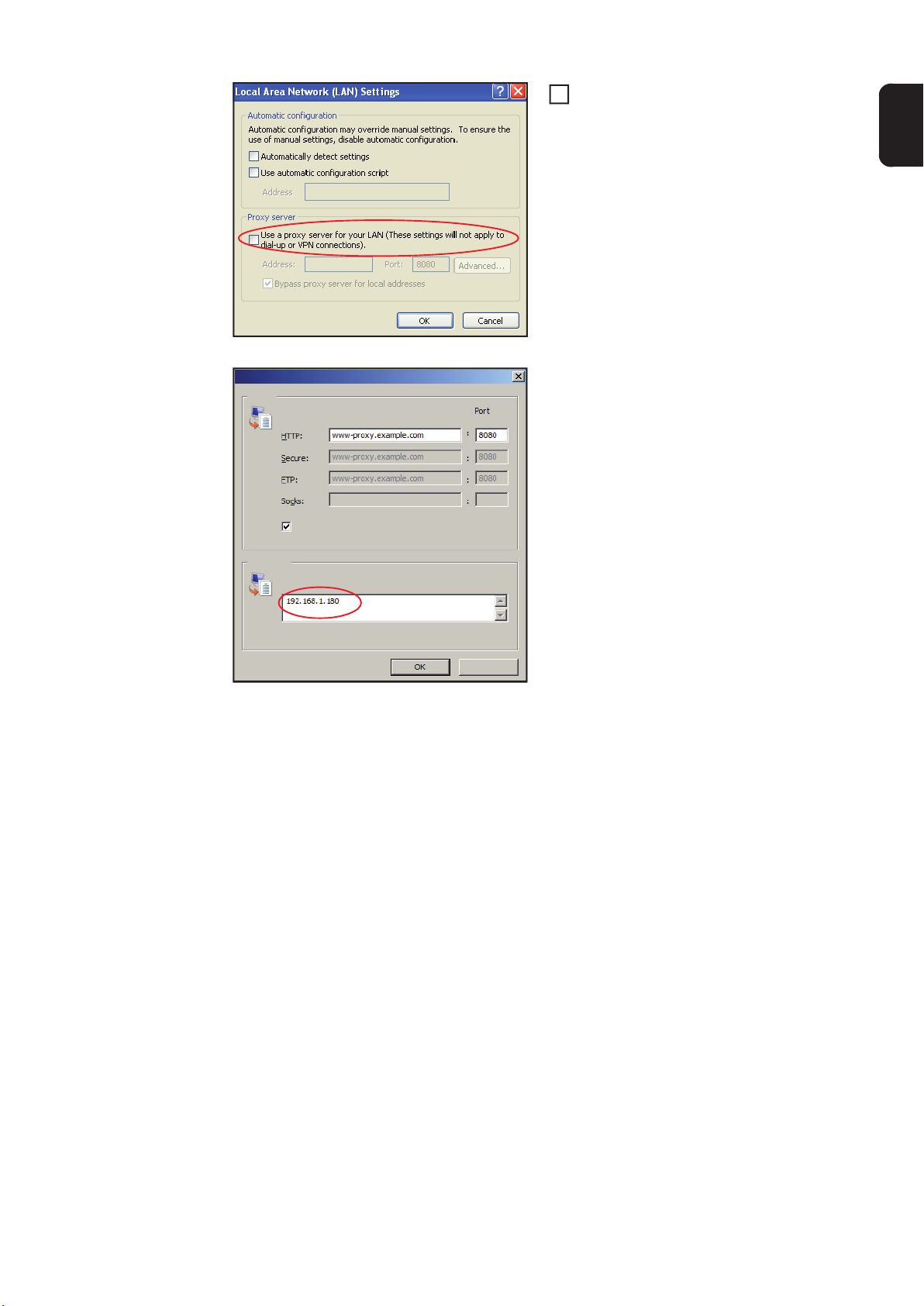
www.proxy.exa
When the 'Use a proxy server for your
6
LAN' option is not activated like in the
picture, the setting options below it are
grayed and not accessible.
When 'Use a proxy server for your
LAN' is activated:
- Click on 'Advanced'
EN-US
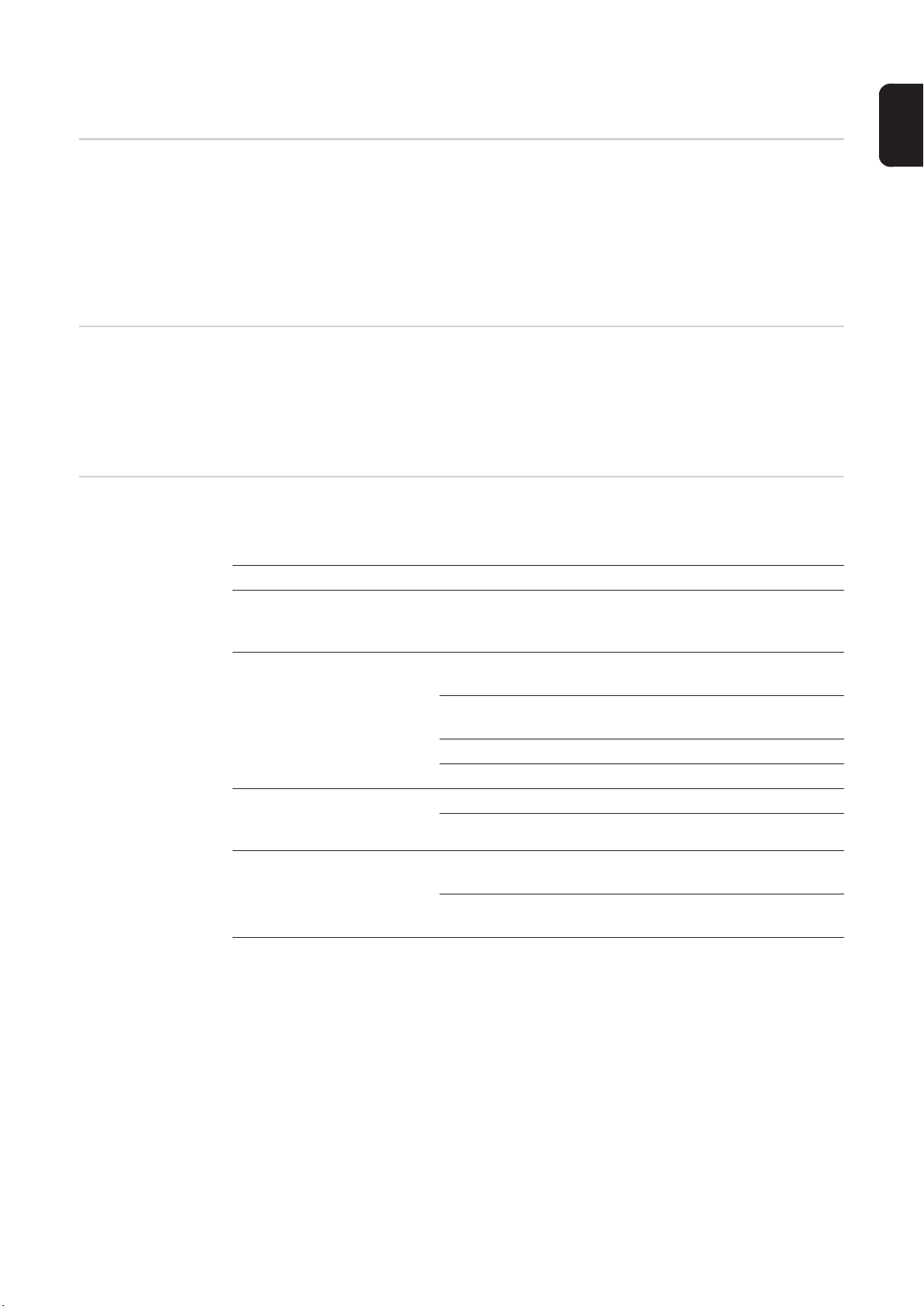
Proxy Settings
Servers
Proxy address to use Type
Use the same proxy server for all protocols
Exceptions
Do not use proxy server for addresses beginning with:
Use semicolons ( ; ) to separate entries.
- Enter the IP address of the 'Fronius
Datalogger Web' in the 'Exceptions'
field, e.g., 192.168.1.180
- Click on "OK"
Cancel
25

Connecting to 'Fronius Datalogger Web' via Internet
browser
General The connection to the 'Fronius Datalogger Web' via an Internet browser is suitable for ac-
cessing simple information by several PC users in a LAN (e.g., company networks,
schools).
For example, total and daily yields can be accessed and/or inverter comparisons can be
made on the 'Fronius Datalogger Web' website.
Requirements - At least a LAN or WLAN connection
- Internet browser (e.g., Microsoft Internet Explorer IE6.0, Firefox 2)
- PC/laptop in the same network segment as the 'Fronius Datalogger Web'
Connecting to
'Fronius Datalogger Web' via Internet browser
Open Internet browser
1
Enter the IP address or the hostname and domain name of the 'Fronius Datalogger
2
Web'
The 'Fronius Datalogger Web' website will appear.
http://169.254.0.180
For the network
administrator
26
Assign an IP address or hostname as per the section 'Fronius Datalogger Web network
configuration'.
To access the Datalogger website outside of the LAN:
- Configure the network router so that requests are forwarded to port 80/TCP on the Datalogger

Connecting to 'Fronius Datalogger Web' via 'Fronius
Solar.access'
General The connection to the 'Fronius Datalogger Web' via 'Fronius Solar.access' is suitable for
detailed long-term data recording and offers full settings options and data preparation for
the photovoltaic system.
Requirements - At least a LAN or WLAN connection
- Internet browser: Microsoft Internet Explorer IE6.0
- Network configuration of Datalogger as per section 'Fronius Datalogger Web network
configuration'
- PC/laptop in the same network segment as the 'Fronius Datalogger Web'
- PC/laptop operating system: Win 2000, Win XP, Win Vista or Win 7
- 'Fronius Solar.access' software installed on the PC/laptop (the 'Fronius Solar.access'
software is included on the CD)
- Photovoltaic system created in 'Fronius Solar.access' as per 'Fronius Solar.access'
online help (Open 'Fronius Solar.access' / Administration / PV Systems / Set up PV
System)
EN-US
Connecting to
'Fronius Datalogger Web' via 'Fronius
Solar.access'
*)
*) Assigned IP address or assigned hostname for 'Fronius Datalogger Web'
Open the 'Fronius Solar.access' software
1
Select "PV Systems"
2
Select the desired photovoltaic system
3
After a short time, the connection to the selected photovoltaic system is established.
'Online' and the version of the Datalogger will be displayed in the bottom left status
bar.
27

For the network
administrator
To access the Datalogger outside of the LAN:
- Configure the network router so that requests are forwarded to port 80/TCP and port
15015/TCP on the Datalogger
28

Connecting to 'Fronius Datalogger Web' via the Internet and 'Fronius Solar.web'
General Using the connection to the 'Fronius Datalogger Web' via the Internet and 'Fronius So-
lar.web,' you can access archived data and realtime PV system data from anywhere via
the Internet.
In addition, you can also provide other users with guest access so that they can view your
photovoltaic system as well as make a comparison of several systems.
EN-US
Function overview
Requirements - Internet access
The Datalogger is connected to the Internet (e.g., via a DSL router). The Datalogger logs
on to 'Fronius Solar.web' on a regular basis and sends its saved data every day.
'Fronius Solar.web' can establish active contact with 'Fronius Datalogger Web', e.g., to display realtime data.
- Internet browser
IMPORTANT! 'Fronius Datalogger Web' cannot connect to the Internet by itself. A
router must be used for a DSL connection to the internet.
- Registration of photovoltaic system with 'Fronius Solar.web' (1)
The Datalogger ID is required for registration. The Datalogger ID is available in Settings / System Information.
- In order to access realtime data in 'Fronius Solar.web,' the 'Yes' option must be activated under 'Send current data to Solar.web' in 'Fronius Datalogger Web' (2)
- In order to access archived data in 'Fronius Solar.web,' the 'Daily at' or 'Hourly' selection option must be activated under 'Send archive data to Solar.web' in 'Fronius Datalogger Web' (3).
(3)
(3)
(1)
(2)
29

Accessing data
from 'Fronius Datalogger Web' via
the Internet and
'Fronius Solar.web'
To access realtime and archived data from 'Fronius Datalogger Web' using 'Fronius Solar.web':
Open the 'Solar Electronics' heading on the Fronius website 'www.fronius.com'
1
Start 'Fronius Solar.web'
2
For more information about 'Fronius Solar.web,' see the online help.
For the network
administrator
Configure the firewall so that the IP address of the Datalogger can send data to port 49049/
UDP from 'solarweb.fronius.com.'
DSL routers mostly enable you to send data to the Internet and, therefore, do not normally
have to be configured.
30
Calculating the data volume
General During operation of the 'Fronius Datalogger Web' data accumulate, that must be transmit-
ted over the internet.
Calculating the data volume is necessary for the selection of an appropriate internet connection.
The following calculation of the data volume provides an overview about the amount of
data accumulating during the operation of the 'Fronius Datalogger Web'.
EN-US
Firmware versions for calculating the data
volume
Calculating the
data volume
The calculation of the data volume is based on the 'Fronius Datalogger Web' firmware version V 2.3.x-x and below.
Due to expanded range of functions higher firmware versions may cause a higher data volume.
The calculation of the data volume depends on the active functions of the 'Fronius Datalogger Web'.
Function Data volume
Making available current
data within 'Fronius Solar.web'
Viewing current data in
'Fronius Solar.web'
Sending archive data /
logging data to 'Fronius
Solar.web'
Communication of service messages or errors
1)
2)
3)
only after a data logger reboot or a disconnected internet connection
Calculation of the memory sectors per day according to chapter "Logging" section
"Calculating memory capacity"
depends on the quality of ther internet connection
singular
Current total view
per sensor card / sensor box
Current comparison view
per inverter
website 0 kByte/h
PV system comparison view 0 kByte/h
transmission time
With daily communication
per service message or error
With immediate communication
per service message or error 1 kByte
1)
(memory sectors per day 2) x 4 kByte) + 8 kByte
3)
600 Byte/Minute
150 Byte
32 kByte/h
42 kByte/h
+ 300 kByte/h
13 kByte/h
+ 4 kByte/h
1 kByte/day
+ 300 Byte
IMPORTANT! Since the values listed in the table are "raw data" of the 'Fronius Datalogger
Web' and due to differences by various counting variants at the providers settlement, increase the calculated total value about 10 - 20 %.
If the functions are disabled, no data volume accumulates.
31

An update of the 'Fronius Datalogger Web' firmware also requires a certain data volume.
This data volume depends on the size of the update package and can not be considered
in the pre-calculation of the data volume.
Calculation examples
Example 1 - home PV system
1 inverter;
No sensor card / sensor box;
The ‘Fronius Datalogger Web‘ has a 24 h
internet connection;
Archive data are sent to the 'Fronius Solar.web';
30 minutes transmission time;
Inverter runs 14 h/day;
15 minutes save interval;
(according to section “Calculating memory
capacity“ 1 memory sector per day results)
Current data are daily viewed for 15 minutes
Average error rate is assumed to be one
service message per day
Subtotal without safety 0,15 kByte
+ (1 memory sectors/day x 4 kByte) + 8 kByte
+ 1 service message x 1 kByte = 1 kByte
+ 32 kByte/h x 24 h = 768 kByte
+ 0,6 kByte/min x 30 min = 18 kByte
+ 42 kByte/h x 0,25 h = 10,5 kByte
+ 0,15 kByte
= 12 kByte
768,00 kByte
18,00 kByte
12,00 kByte
10,50 kByte
1,00 kByte
809,65 kByte
Safety factor is calculated with 10% 809,65 kByte + 10 %
End result 890,615 kByte/day
Example 2 - industrial PV system
100 inverters;
10 sensor cards / sensor boxes;
The ‘Fronius Datalogger Web‘ has a 24 h
internet connection;
Archive data are sent to the 'Fronius Solar.web';
120 minutes transmission time;
Inverters run 14 h/day;
5 minutes save interval;
(according to section “Calculating memory
capacity“ 173 memory sectors per day results)
+ 32 kByte/h x 24 h = 768 kByte
+ 0,6 kByte/min x 120 min = 72 kByte
+ (173 memory sectors/day x 4 kByte)
+ 0,15 kByte
+ 8 kByte
= 700 kByte
32

The current total view and the current
comparison view are daily viewed for 2 h.
+ 42 kByte/h x 2 h
+ 300 kByte/h x 10 x 2 h
+ (13 kByte/h + 100 x 4 kByte/h) x 2 h
= 6910 kByte
EN-US
Average error rate is assumed to be 50
service messages per day
Subtotal without safety 0,15 kByte
Safety factor is calculated with 10% 8500,15 kByte + 10 %
End result 9350,165 kByte/day
+ 50 service messages x 1 kByte = 50 kByte
768,00 kByte
72,00 kByte
700,00 kByte
6910,00 kByte
50,00 kByte
8500,15 kByte
(appr. 9,35 MByte/day)
33

General information for the network administrator
General Firewall
Settings
DSL routers mostly enable you to send data to the internet and, therefore, do not normally
have to be configured.
If existing firewall rules block the connection to the Fronius system monitoring, the following firewall rules must be added:
49049/UDP
output
Sending service messages x -
Connecting to Datamanager via Fronius Solar.web x -
Connecting to Datamanager via Fronius Solar.access
or Fronius Solar.Service
Accessing the Datamanager website - x
Configure the firewall so that the IP address of Fronius system monitoring can send data
to port 49049/UDP from “fdmp.solarweb.com”.
*) We recommend only allowing access to the web interface of the Fronius system monitoring from a secure network. If access via the internet is absolutely necessary (e.g. for service purposes during a limited time period), configure the network router so that requests
for any external port are redirected to port 80/TCP.
Caution - this will make the inverter visible on the internet and more likely to be subject to
network attacks.
-x
80/TCP *)
input
Sending service
messages via a
DSL Internet connection
Using 'Fronius
Solar.web' and
sending service
messages
Normally, no additional router configuration is required for a regular DSL Internet connection for accessing 'Fronius Solar.web' and/or sending service messages, because connections from the LAN to the Internet are open.
However, an Internet connection is required to use 'Fronius Solar.web' and send service
messages.
'Fronius Datalogger Web' cannot connect by itself to the Internet. A router must be used
for a DSL connection to the Internet.
34

'Fronius Datalogger Web' views
Overview The following views are displayed on the 'Fronius Datalogger Web' website:
- Current total view
- Current comparison view
Current total view The Current total view contains:
- PV system power data
-CO2 savings per day and total
- Yield per day and total
- Sensor Card data (if available)
EN-US
(1)
(1)
Sensor Card data in graphic display (1):
the first three measuring channels of ‘Sensor Card 1’ are displayed
Sensor Card data under graphic display (2):
starting with Sensor Card 0, the first four active measuring channels of Sensor Cards available in the system are displayed
(1)
)2()2(
Current comparison view
Several inverters in the same PV system can be compared to each other in the Current
comparison view.
The realtime inverter AC power is displayed as a percentage of the power from the solar
module connected to the respective inverter (shown in a bar diagram). A bar is displayed
for each inverter. The bar color indicates the power range of the inverter:
Green: the inverter power corresponds to the average power of all inverters
Yellow: the inverter power deviates slightly from the average power of all inverters
Red: the inverter power deviates strongly from the average power of all invert-
ers or an error has occurred in the inverter
35

36

'Fronius Datalogger Web' settings
Overview The following selection options are available in the 'Settings' menu of the 'Fronius Datalog-
ger Web' website:
EN-US
Accessing and
editing selection
options
- Passwords
- Date / Time *)
- Views
- Logging
- Network
*) The Date/Time setting is mandatory
The individual selection options will be explained in the following sections.
- Solar.web
- Service Messages
- System Information
- Firmware Update
Connect to 'Fronius Datalogger Web'
1
Click on the 'Settings' menu item
2
Click on the desired selection option
3
The desired selection option will open
View/Edit selection option
4
If required, click on the respective but-
5
ton (e.g., Save, Synchronize, Update)
The changed data are applied.
37

Passwords
General Access to 'Fronius Datalogger Web' is regulated by assigning passwords.
There are 2 different password types available:
- The user password
- The administrator password
IMPORTANT New passwords are only activated when the 'IP address' switch on the Datalogger is set to 'assigned IP.'
Passwords
User password An assigned user password only gives the user read access to 'Fronius Datalogger Web.'
The user cannot open the 'Settings' menu.
Users must enter their username and password every time they connect to 'Fronius Datalogger Web.'
Username = user
38

Administrator
Password
An assigned administrator password gives the user both read and write access to 'Fronius
Datalogger Web.' The user can then open the 'Settings' menu and make any changes as
desired.
When assigning an administrator password, the user must enter the username and password in 'Fronius Datalogger Web' to open the 'Settings' menu.
Username = admin
EN-US
Forgot Your
Password?
Make a direct connection to 'Fronius Datalogger Web' as per the 'Quick Installation'
1
leaflet
http://www.fronius.com/QR-link/4204101438
Fronius Datalogger Web Quick installation
The 'Fronius Datalogger Web' website will appear (no request for passwords)
Enter new passwords
2
39

Time/Date
General The date and time have several tasks in the system.
The time and date are saved for every data record that is logged.
You must set the time and date in order to operate 'Fronius Datalogger Web'. This is the
only way in which Datalogger data can be recorded.
Time/Date
(1)
(4)
(6) (7) (8)
(1)
(4)
(7)
(6)
(2)
(5)
(9) (10)
(5)
(7a)
(3)
)3()2(
(8)
40
(1) Datalogger time display
(2) Datalogger date display
(3) Datalogger time zone
(9)
(7b)
(10)

(4) Date/Time setting option: synchronize to PC/laptop or manual
(5) Automatically adjust for daylight savings time
IMPORTANT For the automatic daylight savings time setting, the correct time zone must
be selected.
(6) Time from PC/laptop for PC synchronization setting Field for setting the time for the
manual setting
(7) Date from PC/laptop for PC synchronization setting
(7a) Calendar icon
(7b) Calendar (opens when you click on the calendar icon)
(8) Field for setting the time zone
(9) 'Synchronization' button
(10) 'Cancel' button
EN-US
41

Views
General Configuration of the ‘Fronius Datalogger Web’ website takes place in the views. The lan-
guage, yield and data for the Comparison and Total view can be set here. A sub-menu is
available for settings related to inverters and Sensor Cards.
Views
(1)
(3)
(2)
'General' view You can enter the charge rate per kWh and the currency for calculating the yield in 'Yield'
(1). The yield is shown in the Current total view.
You can enter the CO2 savings per kWh and the unit for calculating the CO2 savings in
‘CO2 factor’ (2). The CO2 savings are shown in the Current total view.
42
The 'Fronius Datalogger Web' website will appear in the language set in the browser or in
the last language selected. The language can be changed in the language selection fields
(3).

Inverter views
The data for the comparison view is defined in ‘Inverters:’
Select an inverter to be displayed in the Comparison view
1
Enter the respective solar module power for each inverter (the nominal output of the
2
inverter is entered by default)
Assign PV power to the respective inverter using the 'Accept' button
3
Click on 'Save'
4
EN-US
Sensor Card
views
The settings for the Comparison view are applied.
A specific channel name can be assigned to each sensor value of a Sensor Card in ‘Sensor
Cards’ (e.g., wind speed).
Select Sensor Card for which the channel names are to be changed
1
Enter the desired channel names
2
43

Click on 'Save'
3
The settings for the Total view are applied.
44

Logging
General The Datalogger saves the realtime data of all inverters as well as all sensor cards and Fro-
nius sensor boxes integrated into the system at regular intervals. The save interval can be
defined in a range of 5 - 30 minutes.
The data can be prepared, archived and viewed easily with a PC or laptop using the "Fronius Solar.access" software.
Logging
EN-US
Memory capacity The Datalogger has a memory capacity of up to 5 years and 7 months for a PV system with
one inverter and a save interval of 15 minutes.
However, the memory capacity is reduced accordingly depending on the number of inverters and/or Fronius sensor cards/boxes that are integrated into the system.
Calculating memory capacity
Determine logging points for inverters and Fronius sensor cards/boxes
1
Logging points per day =
Logging duration [min]
- For inverters: e.g., 14 hours = 840 minutes
- For Fronius Sensor Card/Fronius Sensor Box: 24 hours = 1440 minutes
Establish total of logging points
2
Total of logging points =
= (number of inverters x logging points per day) + (number of Fronius Sensor Cards /
boxes x logging points per day)
Determine memory sectors per day
3
Logging duration [min]
Save interval [min]
45

Memory sectors per day =
Round to whole numbers
4
Determine memory capacity
5
Total of logging points
114
Calculation example
Memory capacity [days] =
2048
Memory sectors per day
2 inverters, logging duration = 14 hours (840 minutes)
1 Fronius Sensor Card, logging duration = 24 hours (1440 minutes)
Save interval = 15 minutes
1. Logging points per day:
840 min
Inverter logging points =
15 min
1440 min
Sensor Card logging points =
15 min
2. Total logging points:
Total logging points = (2 x 56) + (1 x 96) = 208
(2 x 56) ... 2 inverters, (1 x 96) ... 1 Sensor Card
= 56
= 96
Overwriting data
when memory is
full
3. Memory sectors per day:
Memory sectors =
4. Rounded:
1,825 2
5. Memory capacity [days]:
Memory capacity =
Memory capacity [days] =
When the Datalogger memory is full, the oldest data will be overwritten by the newest data.
2048
= 1024 days (= 2 years, 9 months, 18 days)
2
Memory sectors per day
208
= 1,825
114
2048
‘Delete Data’ button
46
All ‘log data’ saved to ‘Datalogger Web’ is deleted using the ‘Delete Data’ button.

IMPORTANT The power supply to ‘Datalogger Web’ must not be interrupted during the deletion process.
EN-US
47

Network
General The 'Network' selection option is used to configure 'Fronius Datalogger Web' for integration
with an existing network.
For more information about network configuration for 'Fronius Datalogger Web,' please see
the section 'Fronius Datalogger Web network configuration.'
Network
Network diagnostics
The ‘Network diagnostics’ selection option under 'Network' is used to enter ‘ping’ and ‘trace
route commands.’
48

‘Ping command’
The ‘ping command’ is used to determine whether or not a ‘host’ is available and how much
time a data transfer will take.
Sending a ‘Ping command’:
Enter a host name in the ‘Host’ field
1
Click on the ‘Ping’ button
2
EN-US
- ‘Ping command’ is sent
- The resulting data is displayed
‘Trace route command’
A ‘trace route command’ is used to determine the intermediate stations the data takes to
reach the ‘host.’
Sending a ‘trace route command’:
Enter a host name in the ‘Host’ field
1
Click on the ‘Trace route’ button
2
- ‘Trace route command’ is sent
- The resulting data is displayed
49

Solar.web
General The 'Solar.web' selection option is used to make a direct connection to 'Fronius Solar.web'
from 'Fronius Datalogger Web.'
For more information about 'Fronius Solar.web,' please see the section 'Connecting to Fronius Datalogger Web via the Internet and Fronius Solar.web' or the 'Fronius Solar.web' online help.
Solar.web
Daily data transmission to Solar.web
Hourly data transmission to Solar.web
(1)
(4)
If the ‘daily’ selection option is activated, you can select:
- The time of day when data is transmitted (1)
- Whether data is transmitted each day (2)
- Whether data is transmitted only on specific days (3)
If the ‘hourly’ selection option is activated, you can select:
- The times of day when data is transmitted (4)
- Whether data is transmitted each day on the hour every hour (5)
(2)
(3)
(5)
50

Service messages
General Service messages as well as errors from inverters, the 'Fronius String Control,' etc. are
sent to the Datalogger and saved. The 'Service messages' selection option is used to define how service messages are communicated. Communication can take place via:
- E-mail
- Fax
- SMS
- Relay contact
- Buzzer
Service messages can be analyzed further using 'Fronius Solar.web' or 'Fronius Solar.access.'
Service messages
(1)
(2)
EN-US
(7)(6)(5)(4)(3)
(8)
(15)
(24)
(1) PV system name
Included in the service message text
IMPORTANT The system name is used to identify the PV system that sent the
message. Always enter a system name.
(2) Selection field for the language in which the service message should be sent
(3) Message to e-mail recipient
Activate to send service messages to one or more e-mail addresses
(9)
(16)
(18)(17)
(22)
(25)
(19)
(26)
(12)(11)(10)
(20)
(23)
(14)(13)
(21)
(4) Field for up to a max. of 10 e-mail addresses
Separate e-mail addresses with ';'
(5) Selection field to determine whether the service message will be sent immediately
via e-mail or at a specific time
(6) Selection field for the time when a service message will be sent via e-mail
51

(7) 'Send test e-mail' button
(8) Message to fax recipient
Activate to send service messages to a fax number
(9) Field to enter country code
Example: +43 = country code for Austria
(10) Field to enter the fax area code
(11) Field to enter the fax number
(12) Field for sending daily
(13) Selection field for the time when a service message will be sent via fax
(14) 'Send test fax' button
(15) Message to SMS recipient
Activate to send service messages as an SMS to a telephone number
(16) Field to enter country code
Example: +43 = country code for Austria
(17) Field to enter area code
(18) Field to enter the telephone number
(19) Field for sending daily
(20) Selection field for the time when a service message will be sent via SMS
(21) 'Send test SMS' button
IMPORTANT Check your settings by sending a test message.
(22) ‘Save’ button
(23) 'Cancel' button
(24) Field to enter country code
For a direct warning onsite.
Along with the acoustical signal of the buzzer, additional warnings can also be triggered via the relay output (e.g., signal horn, warning light).
The relay contact is an NCC (normally closed contact) and NOC (normally open
contact) and is designed for the following max. voltage/current values:
42 V AC / 6 A
60 V DC / 400 mA
40 V DC / 1 A
30 V DC / 6 A
52
The buzzer and relay are activated or deactivated using the Alarm switch on the
Datalogger. An alarm is acknowledged by switching it briefly to 'Alarm off.'
When 'Alarm on' is selected, the buzzer and relay are briefly activated as a test function.

(25) 'Run test' button
Switches the relay and buzzer on for 1 second when the Alarm switch is set to
'Alarm on'
(26) ‘Reset alarm’ button
Resets a triggered alarm, switches off the relay and buzzer
EN-US
53

System information
General The following system information for 'Fronius Datalogger Web' can be viewed in the 'Sys-
tem information' selection option:
- Datalogger ID - Gateway
- PC board version - DNS server
- Software version - LED states
- System time - IP addresses
- Uptime - Subnet masks
- User agent - MAC address
System information
192.168.1.1
192.168.1.1
192.168.1.180
(1)
(2)
(1) ‘Datalogger restart’ button
Used to restart ‘Datalogger Web’
(2) ‘Reset to factory settings’ button with the following selection options:
All settings except for the network
Used to reset ‘Datalogger Web’ to factory settings.
Network settings remain unchanged.
All settings
Used to reset ‘Datalogger Web’ and network settings to factory settings
54
IMPORTANT Using the ‘Reset to factory settings’ button does not affect the time and date
settings. When ‘Datalogger Web’ is reset to factory settings, the time and date settings
must be checked.

Firmware update
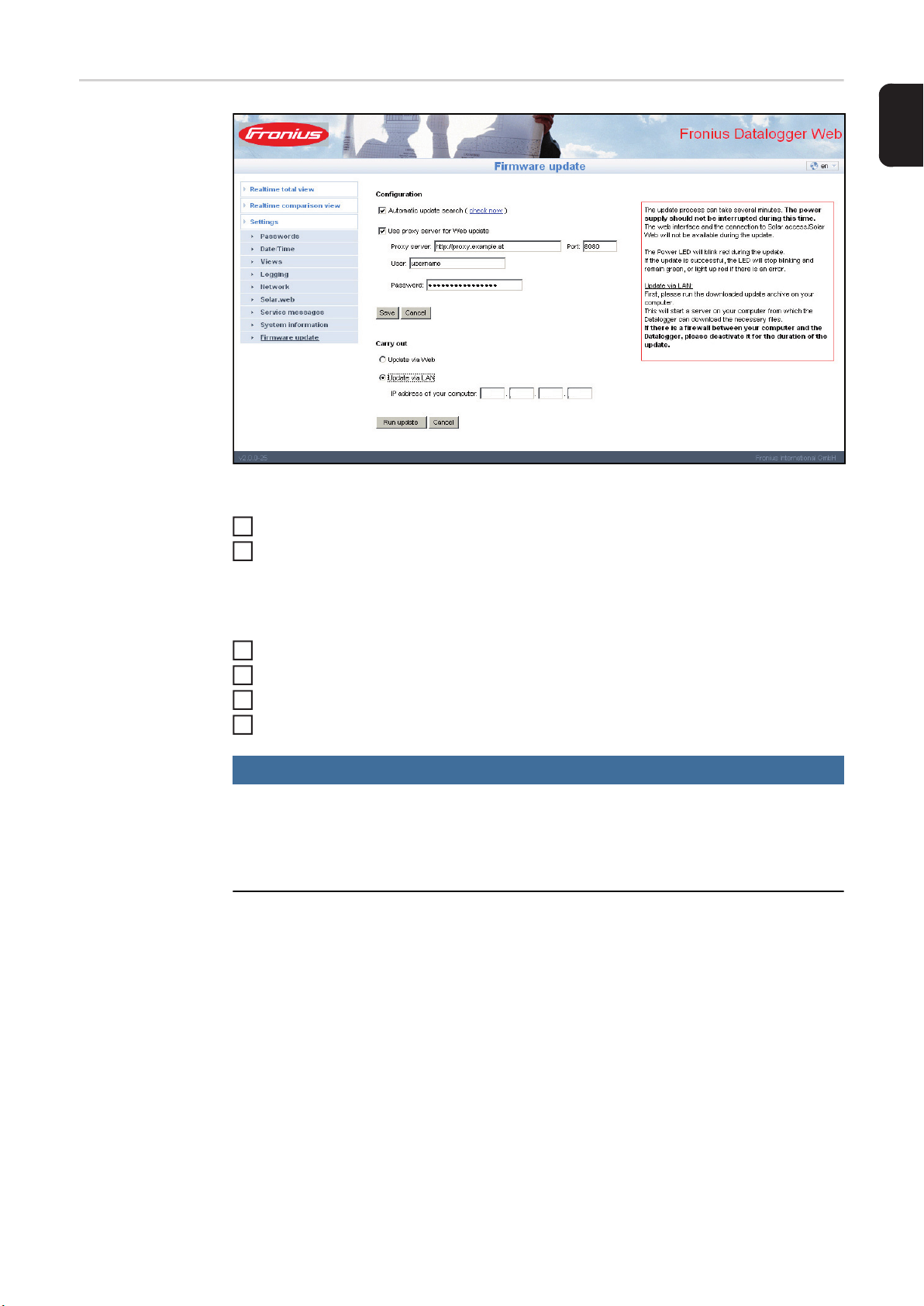
General You can update the ‘Fronius Datalogger Web’ firmware from the ‘Firmware update’ selec-
tion option. A ‘firmware update’ can be carried out via LAN or web.
EN-US
Automatic update
search
When the ‘Automatic update search’ option (1) is activated, ‘Datalogger Web’ will automatically search once a day for updates. If new updates are available, they will be shown in
the grey display bar (2).
(1)
192 168 1 50
(2)
Manual update
search
When the ‘Automatic update search’ function is deactivated, there will be no automatic update search.
To search manually for updates, use the ‘Check now’ button (3)
1
(3)
192 168 1 50
55

Firmware Update
via Web
192 168 1 50
Procedure:
Use your Internet browser to open the 'Fronius Datalogger Web' website
1
Open settings/firmware update
2
Click on the "Run update" button
3
NOTE!
The update process can take several minutes.
The power supply to the 'Fronius Datalogger Web' and the Internet connection should not
be interrupted during this time. The web interface and the connection to 'Fronius Solar.access' or 'Fronius Solar.web' will not be available during the update process. The update is
complete when the "Supply LED" lights up green.
If the connection to the server fails:
- Deactivate the firewall for the duration of the update
- Retry the update
IMPORTANT! If a proxy server is used to connect to the internet:
- The 'Use proxy server for Web update' option must be activated
- The required data must be entered
56
Firmware Update
via LAN
192 168 1 50
Procedure:
Download the current firmware from the Fronius homepage
1
Run the downloaded update file on the PC/laptop
2
EN-US
This will start a web server from which 'Fronius Datalogger Web' will download the required files.
Use your Internet browser to open the 'Fronius Datalogger Web' website
3
Open settings/firmware update
4
Enter the IP address of the PC/laptop
5
Click on the "Run update" button
6
NOTE!
The update process can take several minutes.
The power supply to the 'Fronius Datalogger Web' and the Internet connection should not
be interrupted during this time. The web interface and the connection to 'Fronius Solar.access' or 'Fronius Solar.web' will not be available during the update process. The update is
complete when the "Supply LED" lights up green.
If the connection to the server fails:
- Deactivate the firewall for the duration of the update
- Retry the update
57

Technical Data
Technical data
Memory capacity 16 MB
Supply voltage 12 V DC
Power consumption typ. 1.43 W
Degree of protection IP 20
Dimensions 190 x 114 x 53 mm
4.69 x 4.49 x 2.09 in.
Relay output* 42 V AC / 6 A
60 V DC / 400 mA,
40 V DC / 1 A, 30 V DC / 6 A
Maximum cable cross section for the relay output 0.08 - 1.5 mm²
AWG 14 - 28 (USA/Canada)
Ethernet (LAN)
(WLAN)
RS 485 (Solar Net) RJ 45
External power supply connection 12 V DC, max. 1 A, Class 2
Cable cross section for external power supply connection 0.13 - 1.5 mm²
AWG 16 - 24 (USA/Canada)
Ambient temperature 0 - 50 °C
RJ 45, 100 Mbit
via USB WLAN stick**
32 - 122 °F
* Values are only valid for pure ohmic load
** Available option
58

EN-US
59

Fronius Worldwide - www.fronius.com/addresses
Fronius International GmbH
4600 Wels, Froniusplatz 1, Austria
E-Mail: pv-sales@fronius.com
www.fronius.com
Under www.fronius.com/addresses you will find all addresses of our sales branches and partner firms!
Fronius USA LLC Solar Electronics Division
6797 Fronius Drive, Portage, IN 46368
E-Mail: pv-us@fronius.com
www.fronius-usa.com
 Loading...