

Page 1

/ Battery Charging Systems / Welding Technology / Solar Electronics
Fronius CL 36.0 / 48.0 / 60.0 WYE277
Fronius CL 33.3 / 44.4 / 55.5 DELTA
Operating Instructions
Inverter for grid-connected
EN-US
photovoltaic systems
42,0426,0083,EA 009-01042015
Page 2

Page 3

Dear Fronius Customer,
Introduction
Thank you for choosing Fronius - and congratulations on your new, high-quality, hightech Fronius product. This introduction should provide you with general information
about the equipment. Please read it carefully to learn about the many great features of
your new Fronius product. This is the best way to get the most out of all the advantages
that it has to offer.
Please also note the safety information and the safety precautions for the product
installation location. Following all product instructions will ensure long-lasting quality and
reliability. And these are the essential ingredients for outstanding results.
EN-US
ud_fr_st_et_01382 012012
Page 4

ud_fr_st_et_01382 012008
Page 5

IMPORTANT SAFETY
INSTRUCTIONS
SAVE THESE INSTRUCTIONS
General This manual contains important instructions for the Fronius CL, that must be followed
during installation and maintenance of the inverter.
The Fronius CL is designed and tested according to international safety requirements, but
as with all electrical and electronic equipment, certain precautions must be observed
when installing and/or operating the Fronius CL.
To reduce the risk of personal injury and to ensure the safe installation and operation of
the Fronius CL, you must carefully read and follow all instructions and safety instructions
in these operating instructions.
Failure to follow these instructions and other relevant safety procedures may result in
voiding of the warranty and/or damage to the inverter or other property!
Safety Instructions
Electrical installations
The following section “Safety Instructions“ contains different Warnings. A Warning describes a hazard to equipment or personnel. It calls attention to a procedure or practice,
which, if not correctly performed or adhered to, could result in damage to or destruction of
part or all of the Fronius inverter and/or other equipment connected to the Fronius inverter
or personal injury.
All electrical installations must be made in accordance with the National Electrical Code,
ANSI/NFPA 70, and any other codes and regulations applicable to the installation site.
For installations in Canada the installations must be done in accordance with applicable
Canadian standards.
Page 6

Page 7

Safety Instructions
Explanation of
Safety Warnings!
General
„DANGER!“ Indicates an immediate danger. Death or serious injury may
result if appropriate precautions are not taken.
EN-US
„WARNING!“ indicates a potentially dangerous situation. Death or serious
injury may result if appropriate precautions are not taken.
„CAUTION!“ Indicates a situation where damage or injury could occur. Minor
injury or damage to property may result if appropriate precautions are not
taken.
NOTE! Indicates a situation which could adversely affect work results and may
cause damage to equipment.
„Important“ Highlights tips for correct operation and other particularly useful
information. It does not indicate a potentially damaging or dangerous situation.
If you see any of the symbols depicted in the „Safety Rules,“ special care is required.
This equipment has been manufactured using state-of-the-art technology
and in accordance with general safety regulations. However, incorrect
operation or misuse may endanger:
- the life and well-being of the operator or third parties
- the equipment and other property of the owner/operator
- the efficient operation of the equipment.
All persons involved with equipment startup, service and maintenance must:
- be suitably qualified
- be familiar with electrical installations
- have completely read and followed these operating instructions
The operating instructions must be available at the equipment location at all
times. In addition to the operating instructions, all applicable local rules and
regulations regarding accident prevention and environmental protection must
also be followed.
All safety instructions and warning signs on the equipment itself:
- must be maintained in legible condition
- must not be damaged
- must not be removed
- must not be covered or painted over
For information about where the safety instructions and warning signs are
located on the equipment, please refer to the “General“ section of your
equipment’s operating instructions.
Any equipment malfunctions which might impair safety must be remedied
immediately before the device is turned on.
Your safety is at stake.
I
ud_fr_se_sv_01381 012012
Page 8

Intended Use
The equipment may only be operated in compliance with its intended use.
Any other purpose does not constitute intended use. The manufacturer is not
responsible for any damages resulting from unintended use.
Intended use also includes:
- reading and complying with all general information as well as safety
information and warnings from the operating instructions
- compliance with all inspection and maintenance requirements
- installation as per operating instructions
Where appropriate, the following guidelines should also be applied:
- Utility company regulations regarding grid feed-in
- Information from solar module manufacturer
Ambient Conditions
Qualified Personnel
Operation and/or storage of the device outside of the stipulated range does
not constitute intended use. The manufacturer is not responsible for any
damages resulting from unintended use.
Please refer to the technical data in your operating instructions for information about permitted ambient conditions.
The servicing information contained in these operating instructions is intended
only for the use of qualified service engineers. An electric shock can be fatal.
Please do not perform any actions other than those described in the documentation. This also applies to qualified personnel.
All cables and wires must be secured, undamaged, insulated and adequately
dimensioned. Loose connections, scorched, damaged or under-dimensioned
cables and wires must be repaired immediately by an authorized specialist.
Maintenance and repair may only be carried out by an authorized specialist.
The use of third-party parts does not guarantee that they were designed and
manufactured according to operational demands and safety requirements.
Use only original spare parts (also applies to standard parts).
Safety Precautions at Equipment
Location
ud_fr_se_sv_01381 012012
Do not carry out any alterations, installations or modifications to the device
without first obtaining the manufacturer’s permission.
Immediately replace any components that are not in perfect condition.
When installing devices with air vents, make sure that cool air can flow freely through the
vents unobstructed. The device should only be operated in accordance with the protection class listed on the rating plate.
II
Page 9

Information on
Noise Emission
Values
The inverter generates a maximum sound power level of <80dB(A) (ref.
1pW) at full-load operation according to IEC 62109-1.
The cooling of the device takes place via an electronic temperature control
system at the lowest possible noise level and depends on the power used,
ambient temperature and the soiling level of the device, etc.
A workplace-related emissions value cannot be provided for this device
because the actual noise level that occurs depends strongly on the installation situation, the grid quality, the surrounding walls and the general properties
of the space.
EMC Device
Classifications
Devices in emission class A:
- Are only designed for use in industrial settings
- Can cause grid-bound and radiated interference in other areas
Devices in emission class B:
- Satisfy the emissions criteria for residential and industrial areas.
This is also true for residential areas in which the energy is
supplied from the public low-voltage grid.
EMC device classification as per the rating plate or technical data
EMC Precautions In special cases, there may still be interference for the specified application
area despite maintaining standardized emission limit values (e.g. when
sensitive equipment is located at the setup location or when the setup
location is near radio or television receivers).
In this case, the operator is obliged to take proper action to rectify the
situation.
EN-US
Grid connection
Devices with a high output (> 16 A) can influence the voltage quality of the
grid due to a high current input into the main supply.
This can affect several device types in the form of:
- Connection limitations
- Requirements regarding permitted mains impedance
- Requirements regarding minimum required short circuit power
*)
for each interface to the public grid
*)
*)
See technical data
In this case, the operator or the user of the device must make sure whether
or not the device may be connected, if necessary by contacting the power
supply company.
III
ud_fr_se_sv_01381 012012
Page 10

Electrical Installations
Electrical installations may only be carried out in accordance with relevant
national and local standards and regulations.
ESD Precautions
Safety Precautions in NormalOperation
Safety Markings
Danger of damage to electronic components due to electrostatic discharge.
Take appropriate ESD precautions when replacing and installing components.
The device should only be operated when all safety equipment is fully functional. If safety equipment is not fully functional, there is a danger to:
- the life and well-being of the operator or third parties
- the equipment and other property of the owner/operator
- the efficient operation of the equipment
Safety equipment that is not fully functional must be repaired by an authorized specialist before the device is turned on.
Never bypass or disable safety equipment.
Equipment with the CE marking fulfils the basic requirements of the Guideline Governing Low-Voltage and Electromagnetic Compatibility. (For more
information, please see the attachment and/or the “Technical Data“ section in
your documentation).
Disposal
Data Security
Copyright
This device should not be disposed of in residential waste.
To comply with European Directive 2002/96/EC on Waste Electrical and
Electronic Equipment and its implementation as national law, electrical
equipment that has reached the end of its life must be collected separately
and returned to an approved recycling facility. Any device that you no longer
require must be returned to your dealer or you must find an approved collection and recycling facility in your area.
Ignoring this EU Directive may have adverse affects on the environment and
your health.
The user is responsible for backing up data relating to changes made to
factory settings. The manufacturer will not accept liability if personal settings
are deleted.
The manufacturer maintains the copyright to these operating instructions.
Text and illustrations are technically correct at the time of going to print. The
right to make modifications is reserved. The contents of the operating instructions shall not provide the basis for any claims whatsoever on the part
of the purchaser. We would be grateful for any comments or suggestions
regarding improvements and/or error corrections for the operating instructions.
ud_fr_se_sv_01381 012012
IV
Page 11

Table of Contents
Protection of Persons and Equipment ............................................................................................................ 5
Safety ........................................................................................................................................................ 5
Protection of Persons and Equipment ....................................................................................................... 5
Galvanic Isolation ...................................................................................................................................... 5
Monitoring the Grid .................................................................................................................................... 5
Information about Field Adjustable Trip Points .......................................................................................... 5
FCC Compliance ....................................................................................................................................... 5
Ground Fault Detector / Interrupter ........................................................................................................... 6
Standards and Regulations ....................................................................................................................... 6
Product Listings and Compliance .............................................................................................................. 6
Warning notices affixed to the device........................................................................................................ 7
Use in accordance with "intended purpose" ................................................................................................... 8
Use in accordance with "intended purpose" .............................................................................................. 8
Field of application .................................................................................................................................... 8
Photovoltaic system stipulations ............................................................................................................... 8
Operating Principle ......................................................................................................................................... 9
Fully Automatic Operational Management ................................................................................................ 9
The MIXTM Concept ................................................................................................................................ 9
Reliability ................................................................................................................................................... 9
Power Derating ......................................................................................................................................... 9
Forced Ventilation ................................................................................................................................... 10
The Fronius CL Unit in the PV System .......................................................................................................... 11
General .................................................................................................................................................... 11
Tasks ........................................................................................................................................................ 11
Converting DC into AC Current ................................................................................................................ 11
Display function and data communication ................................................................................................ 11
Data Communications Components............................................................................................................. 12
Data Communications Components........................................................................................................ 12
Fronius Com Card ................................................................................................................................... 12
Fronius Modbus Card.............................................................................................................................. 12
Fronius Datalogger .................................................................................................................................. 12
Fronius Sensor Card / Box ...................................................................................................................... 12
Fronius Interface Card and Fronius Interface Card easy ........................................................................ 12
Fronius String Control 250/25 ................................................................................................................. 12
Inverter Product Description ......................................................................................................................... 13
Inverter Product Description (doors closed) ............................................................................................ 13
Inverter Product Description (doors opened) .......................................................................................... 14
Connection Area Product Description .......................................................................................................... 15
Connection Area Product Description ..................................................................................................... 15
Terminals in the Area of the Isolated Relay Contact................................................................................ 16
Installation and Connection Accessories ................................................................................................. 16
Choosing the Location ................................................................................................................................. 17
Choosing the Location in General ........................................................................................................... 17
Criteria for Location Selection ................................................................................................................. 17
Unsuitable Locations ............................................................................................................................... 17
Transport ...................................................................................................................................................... 18
Transport ................................................................................................................................................. 18
Crane Transport Using Forks .................................................................................................................. 19
Transport Using a Forklift or Lift Truck .................................................................................................... 19
Manual Transport .................................................................................................................................... 19
Removing Power Stage Sets ........................................................................................................................ 20
Opening the Fronius CL .......................................................................................................................... 20
Removing Power Stage Sets ................................................................................................................... 20
1
Page 12

Requirements for Installing the Fronius CL .................................................................................................. 21
Additional External AC and/or DC Disconnect ........................................................................................ 21
Using the Mounting Base ........................................................................................................................ 21
Use of aluminum wires ............................................................................................................................ 21
Inverter Cabling ....................................................................................................................................... 21
Side Cabling ............................................................................................................................................ 21
Bottom Cabling........................................................................................................................................ 22
Fronius CL Installation.................................................................................................................................. 23
Safety ...................................................................................................................................................... 23
Preparing AC and DC Wires ................................................................................................................... 23
Positioning the Mounting Base ................................................................................................................ 24
Installation of several inverters ................................................................................................................ 24
Installing the Mounting Base ................................................................................................................... 25
Preparing the Fronius CL ........................................................................................................................ 26
Positioning the Fronius CL on the Mounting Base .................................................................................. 27
Positioning the Fronius CL on the Mounting Base Using a Crane .......................................................... 27
Positioning the Fronius CL on the Mounting Base Using a Crane and Forks, a Forklift or a Lift Truck ... 28
Manually Positioning the Fronius CL on the Mounting Base ................................................................... 28
Securing the Fronius CL to the Mounting Base ....................................................................................... 29
Cross Section of AC and DC Wires .............................................................................................................. 30
Maximum Wire Cross Section ................................................................................................................. 30
Minimum Cross Section of AC Wires ...................................................................................................... 30
Minimum Cross Section of DC Wires ...................................................................................................... 31
Cable Lugs for AC and DC Wires............................................................................................................ 31
Connecting the Fronius CL to the Public Grid (AC) ...................................................................................... 32
Overview of Available Power Grids ......................................................................................................... 32
Monitoring the Grid .................................................................................................................................. 33
AC Terminals ........................................................................................................................................... 33
Possible Connections to the Ground terminal ......................................................................................... 34
Safety ...................................................................................................................................................... 34
Connecting the Fronius CL to the Public Grid (AC) ................................................................................. 35
Connecting aluminium wires ................................................................................................................... 35
AC Connection Examples ....................................................................................................................... 36
Recommendation for the AC-side Overcurrent Protection ...................................................................... 36
Connecting DC Wires to the Fronius CL ...................................................................................................... 37
General Information about Solar Modules .............................................................................................. 37
Safety ...................................................................................................................................................... 37
DC Terminals ........................................................................................................................................... 38
Connecting aluminium wires ................................................................................................................... 38
Connecting DC Wires.............................................................................................................................. 39
DC Connection Examples ....................................................................................................................... 39
Fronius CL Solar Module Ground ................................................................................................................. 41
General ................................................................................................................................................... 41
Solar Module Ground via Fuse ............................................................................................................... 41
Safety ...................................................................................................................................................... 42
Solar Module Ground at Negative Pole ................................................................................................... 42
Solar Module Ground at Positive Pole - Inserting Fuse .......................................................................... 42
Inserting Power Stage Sets .......................................................................................................................... 43
Overview ................................................................................................................................................. 43
General ................................................................................................................................................... 43
Slot Arrangement .................................................................................................................................... 44
Dip Switches for Identifying Power Stage Set Racks ..............................................................................44
Dip Switch Settings for Each Slot ............................................................................................................ 44
Inserting Power Stage Sets ..................................................................................................................... 45
Application Example ................................................................................................................................ 46
Closing the Fronius CL ................................................................................................................................. 47
Closing the Fronius CL ............................................................................................................................ 47
Start-up Operation ........................................................................................................................................ 48
Requirements for Start-up Operation ...................................................................................................... 48
Start-up Operation ................................................................................................................................... 48
Factory Pre-set Configuration ................................................................................................................. 48
2
Page 13

Selecting the Public Grid ......................................................................................................................... 49
Startup Phase during Startup Operation .................................................................................................. 50
Setting inverter for solar module ground at the positive pole .................................................................. 52
Selecting the Interface Protocol and Setting the Inverter Baud Rate ........................................................... 54
General ................................................................................................................................................... 54
Entering the access code ........................................................................................................................ 54
Selecting the interface protocol for communication with other data communication components........... 55
Setting the inverter baud rate .................................................................................................................. 56
Setting the Relay Contact Functions ............................................................................................................ 58
General ................................................................................................................................................... 58
Possible Functions of Relay Contacts ..................................................................................................... 58
Entering the access code ........................................................................................................................ 59
Setting the relay contact functions .......................................................................................................... 60
Inserting Option Cards ................................................................................................................................. 61
Safety ...................................................................................................................................................... 61
Opening the Fronius CL .......................................................................................................................... 61
Connecting Option Cards, Laying Data Communication Wires ............................................................... 62
Inserting Option Cards ............................................................................................................................ 62
Closing the Fronius CL ............................................................................................................................ 64
Solar Net and Data Communication ............................................................................................................. 65
Solar Net ................................................................................................................................................. 65
Data Communication ............................................................................................................................... 65
Application Example ................................................................................................................................ 66
Keys and Symbols ....................................................................................................................................... 67
Keys and Symbols .................................................................................................................................. 67
Display .................................................................................................................................................... 67
Operating Status LED ............................................................................................................................. 69
Startup Phase and Grid Feed-in Mode ......................................................................................................... 70
Startup Phase.......................................................................................................................................... 70
Test Procedure ........................................................................................................................................ 70
Operation of Feeding Energy into the Grid .............................................................................................. 71
Activating Display Backlight .................................................................................................................... 72
Automatic Deactivation of Display Illumination / Switching to the ‘Now’ Display Mode ........................... 72
Navigation in the Menu Level ....................................................................................................................... 72
Accessing Menu Levels .......................................................................................................................... 72
Selecting a Display Mode ........................................................................................................................ 73
Display Modes .............................................................................................................................................. 73
Display Modes ........................................................................................................................................ 73
Overview of Display Values ..................................................................................................................... 74
Display Values in the ‘Now’ Display Mode .................................................................................................... 75
Selecting the ‘Now’ Display Mode ........................................................................................................... 75
Display Values in the ‘Now’ Display Mode ............................................................................................... 75
Options .................................................................................................................................................... 77
Display Values in the ‘Day / Year / Total’ Display Modes .............................................................................. 78
General ................................................................................................................................................... 78
Selecting ‘Day / Year / Total’ Display Modes ........................................................................................... 78
Display Values in the ‘Day / Year / Total’ Display Modes ......................................................................... 79
Options .................................................................................................................................................... 80
The Setup Menu ........................................................................................................................................... 81
Default Settings ....................................................................................................................................... 81
Accessing the Setup Menu ..................................................................................................................... 81
Scrolling through Menu Items ................................................................................................................. 82
Menu Items in the Setup Menu ............................................................................................................... 82
Setting and Displaying Menu Items .............................................................................................................. 87
General Menu Item Settings ................................................................................................................... 87
Exiting a Menu Item ................................................................................................................................ 87
Setting Standby Mode - Manual Shutoff of Feeding Energy into the Grid ............................................... 87
Restoring the Grid Feed .......................................................................................................................... 88
Setting the Display Contrast .................................................................................................................... 88
Setting the Display Illumination ............................................................................................................... 89
Setting the Currency and Rate ................................................................................................................ 90
3
Page 14

Setting the CO2 Reduction Factor .......................................................................................................... 91
Setting the Offset Value for Total Energy Display and Measurement Correction Value ........................... 92
Setting the Inverter Number .................................................................................................................... 94
Displaying and Setting Parameters in the ‘DATcom’ Menu Item .............................................................. 95
Setting the Time and Date....................................................................................................................... 96
Displaying the Status of the Fans............................................................................................................ 99
Displaying the Status of the Power Stage Sets ..................................................................................... 100
Displaying the Version........................................................................................................................... 101
Setup Lock function .................................................................................................................................... 104
General ................................................................................................................................................. 104
Activating/deactivating the "Setup Lock" function ................................................................................. 104
Status Diagnosis and Troubleshooting ....................................................................................................... 106
Displaying Status Codes ....................................................................................................................... 106
Normal Operation Status Codes ........................................................................................................... 106
Total Failure ........................................................................................................................................... 106
Power Stage Set Error Status Codes .................................................................................................... 107
Class 1 Status Codes ............................................................................................................................ 108
Class 2 Status Codes ............................................................................................................................ 109
Class 3 Status Codes ............................................................................................................................. 110
Class 4 Status Codes ............................................................................................................................. 112
Class 5 Status Codes ............................................................................................................................. 117
Customer Service.................................................................................................................................. 120
Maintenance............................................................................................................................................... 121
Safety .................................................................................................................................................... 121
General ................................................................................................................................................. 121
Opening the Fronius CL for Service/Maintenance ................................................................................ 121
Operation in Dusty Environments.......................................................................................................... 122
Replacing Solar Module Ground Fuses ..................................................................................................... 124
Safety .................................................................................................................................................... 124
Opening the Fronius CL ........................................................................................................................ 125
Replacing Solar Module Ground Fuses at the Positive Pole ................................................................. 126
Replacing Solar Module Ground Fuses at the Negative Pole ............................................................... 126
Closing the Fronius CL .......................................................................................................................... 127
Replacing Power Stage Sets...................................................................................................................... 128
Safety .................................................................................................................................................... 128
Opening the Fronius CL ........................................................................................................................ 128
Removing Defective Power Stage Sets ................................................................................................. 129
Sticker for Replacing Power Stage Sets ................................................................................................ 130
Inserting Replacement Power Stage Sets ............................................................................................. 131
Closing the Fronius CL .......................................................................................................................... 132
Technical Data ............................................................................................................................................ 133
Fronius CL 33.3 delta ............................................................................................................................ 133
Fronius CL 36.0 wye277 ....................................................................................................................... 135
Fronius CL 44.4 delta ............................................................................................................................ 137
Fronius CL 48.0 wye277 ....................................................................................................................... 139
Fronius CL 55.5 delta ............................................................................................................................ 141
Fronius CL 60.0 wye277 ....................................................................................................................... 143
Explanation of Footnotes ...................................................................................................................... 145
Field Adjustable Trip Points ................................................................................................................... 145
Relevant Standards and Directives ............................................................................................................ 146
Relevant Standards and Directives ....................................................................................................... 146
Grid Failure ........................................................................................................................................... 146
Warranty and Disposal ............................................................................................................................... 147
Fronius Manufacturer’s Warranty .......................................................................................................... 147
Disposal of Obsolete Equipment - Recycling ........................................................................................ 147
4
Page 15

Protection of Persons and Equipment
Safety
Protection of
Persons and
Equipment
WARNING! An electric shock can be fatal. Danger from grid voltage and
DC voltage from solar modules.
- The connection area should only be opened by a licensed electrician.
- Never work with live wires! Prior to all connection work, make sure that
the AC and DC wires are not charged.
WARNING! If the equipment is used or tasks are carried out incorrectly,
serious injury or damage may result. Only qualified personnel are authorized to install your inverter and only within the scope of the respective
technical regulations. It is essential that you read the "Safety regulations"
chapter before commissioning the equipment or carrying out maintenance
work.
The design and function of the inverter provide a maximum level of safety during both
installation and operation.
The inverter provides operator and equipment protection through:
a) galvanic isolation
b) monitoring the grid
Galvanic Isolation
Monitoring the
Grid
Information
about Field
Adjustable Trip
Points
FCC Compliance This device complies with Part 15 of the FCC Rules. Operation is subject to
The inverter is equipped with a high-frequency transformer that ensures galvanic
isolation between the DC side and the grid, thus ensuring the highest possible safety.
Whenever conditions in the electric grid are inconsistent with standard conditions (e.g.,
grid switch-off, interruption), your inverter will immediately stop operating and interrupt
the supply of power into the grid.
Grid monitoring take place through:
- monitoring voltage
- monitoring frequency
- monitoring islanding conditions
The inverter is equipped with field adjustable trip points. For further information, please
contact Fronius technical support at: pv-us-support@fronius.com.
the following conditions:
(1) This device may not cause harmful interference, and
(2) This device must accept any interference received, including interference that may cause undesired operation.
5
Page 16

Ground Fault
Detector / Interrupter
The inverter is equipped with a ground fault detection and interruption (GFDI) circuit as
required by UL 1741 and the National Electrical Code.
Depending on the system configuration, either the positive or negative conductor of the
PV array is grounded in the inverter via a fuse. If a ground fault occurs in the DC wiring,
the inverter disconnects from the grid.
Standards and
Regulations
Product Listings
and Compliance
Your inverter complies with the requirements of the following standards „Inverters,
converters and controllers for use in independent power systems“:
- UL1741
- IEEE 1547
- IEEE 1547.1
- ANSI/IEEE C62.41
- C22.2 No. 107.1-01
- FCC Part 15 B
The ground-fault detection and interruption comply with the NEC 690 building code
requirements.
The respective conformity declarations can be found in the appendix to these operating
instructions.
6
Page 17

Warning notices
affixed to the
device
The interior of the inverter contains warning notices and safety symbols. These warning
notices and safety symbols must NOT be removed, painted over or covered. The
notices and symbols warn against operating the equipment incorrectly, as this may
result in serious injury and damage.
7
Page 18

Use in accordance with "intended purpose"
Use in accordance with
"intended purpose"
Field of application
Photovoltaic
system stipulations
The Fronius CL solar inverter is designed exclusively to convert direct current from
solar modules into alternating current and feed this power into the public grid. The
following are deemed not in accordance with the intended purpose:
- Use for any other purpose, or in any other manner
- Alternations to the Fronius CL that are not expressly recommended by Fronius
- Installation of parts that are not expressly recommended or sold by Fronius
The manufacturer is not responsible for any damages resulting from unintended use. In
addition, no warranty claims will be entertained.
Use in accordance with the "intended purpose" also includes:
- following all the instructions in these operating instructions
- carrying out all the specified inspection and servicing work
The inverter has been designed exclusively for use in grid-connected photovoltaic
systems. It cannot generate electric power independently of the grid.
The inverter is designed exclusively to be connected and used with solar modules. Use
with other DC generators (e.g., wind generators) is not permitted.
When configuring the photovoltaic system, make sure that all photovoltaic system
components are operating completely within their permitted operating range.
All measures recommended by the solar module manufacturer for maintaining solar
module properties must be followed.
8
Page 19

Operating Principle
Fully Automatic
Operational
Management
The MIX
cept
TM
Con-
The inverter is fully automatic. Starting at sunrise, as soon as the solar modules generate enough power, the automatic control unit starts monitoring grid voltage and frequency. After five minutes, if there is a sufficient level of irradiance, your solar inverter starts
feeding energy to the grid.
The control system of the inverter ensures that the maximum possible power output is
drawn from the solar modules at all times.
This function is called MPPT (Maximum Power Point Tracking).
As dusk starts and there is no longer sufficient energy available to feed power into the
grid, the inverter shuts down the grid connection completely and stops operating. All
settings and data recorded are saved.
MIX = Master Inverter X-change
In the MIX concept, several smaller power stage sets operate instead of one large
power stage set:
- When irradiance is low, only 1 - 3 power stage sets turn on in the inverter.
- In this way, the power stage sets operate in a higher partial-load range than a large
power stage set.
- The energy can then be converted more efficiently, thus significantly increasing the
efficiency.
- The control software alternately assigns the “master power stage set” function to all
the power stage sets.
- When irradiance is high, the other power stage sets switch on in sets of 3.
- The “master power stage set” coordinates and controls the operation of the other
power stage sets.
- Operating hours per power stage set are decreased, and the service life of the
power stage sets is increased along with the yield for partial-load operation.
Reliability
Power Derating
The MIX concept ensures a high degree of reliability due to the number of independent
power stage sets:
if one power stage set fails, the remaining power stage sets take over for it. Thus
energy losses are limited and only occur when irradiance is high.
If there is insufficient heat dissipation despite the fan operating at maximum speed (for
example, inadequate heat transfer away from the heat sinks), the power will be derated
to protect the inverter.
Derating the power reduces the output of the inverter for a short period sufficient to
ensure that the temperature will not exceed the permitted limit.
Your inverter will remain ready for operation as long as possible without any interruption.
9
Page 20

Forced Ventilati-onThe inverter is cooled through forced
ventilation via 2 temperature-controlled
fans mounted in the doors. The air drawn
in at the front flows into a closed channel
through the individual racks containing the
power stage sets and then is discharged
out the top.
The closed air channel ensures that the
power stage sets do not come into contact
with the outside air. This ensures that the
power stage sets do not get dirty.
The fan speed and the temperature of the
supply air are monitored.
The power stage sets are hermetically
sealed and have their own fans for circulating the air in the power stage set racks.
The inverter’s speed-controlled fans with
ball bearing support ensure:
- optimal inverter cooling
- higher efficiency
- cooler components, thus improving
service life
- lowest possible energy consumption
and noise level
10
Page 21

The Fronius CL Unit in the PV System
General
Tasks
The Fronius CL solar inverter is the highly complex link between the solar modules and
the public grid.
Inverter
PV Array
Main AC
Load Center
Energy
Meter
The main tasks of the inverter include:
- Converting DC into AC current
- Fully automatic operation management
- Display function and data communication
Converting DC
into AC Current
Display function
and data communication
The inverter transforms the direct current generated by the solar modules into alternating current. This alternating current is fed into your home system or into the public grid
and synchronized with the voltage that is used there.
Important The inverter has been designed exclusively for use in grid-connected photovoltaic systems. It cannot generate electric power independently of the grid.
The display on the inverter is the interface between the inverter and the operator. The
display has a user-friendly design.
The inverter is equipped with a basic logging function to monitor minimum and maximum data on a daily and a cumulative basis. These values are shown on the display.
A wide range of data communication products allows for many possibilities of recording
and viewing data.
11
Page 22

Data Communications Components
Data Communications Components
Fronius Com
Card
Fronius Modbus
Card
The inverter is designed for various data communications components, e.g.:
- Fronius Datalogger Card / Box
- Fronius Datalogger Web
- Fronius Sensor Card / Box
Data communications components are available as plug-in cards or versions with an
external housing. Depending on the version, the inverter can accommodate up to 2
option cards in addition to the standard Fronius Com Card.
The Fronius Com Card enables the inverter to communicate with other inverters or
external data communications components such as Datalogger, String Controls or third
party system monitoring devices.
The Fronius Modbus Card is a system upgrade used to retrieve data from an inverter
via the Modbus protocol.
The Modbus protocol is a master/slave architecture-based communication protocol. The
Fronius Modbus Card communicates with the Modbus Master using register addresses.
The Fronius Modbus Card comes standard with the inverter.
Detailed information about the Fronius Modbus Card according to the enclosed "Fronius
Modbus Card" operating instructions.
- Fronius Interface Card / Box
- Fronius String Control 250/25
Fronius Datalogger
Fronius Sensor
Card / Box
Fronius Interface
Card and Fronius
Interface Card
easy
Control 250/25
The Fronius Datalogger is used to record and manage data from a photovoltaic system
using a PC.
The Fronius Sensor Card / Box is used to integrate various sensors into Solar Net (e.g.,
for temperature, irradiance).
The Fronius Interface Card and the Fronius Interface Card easy are RS 232 interfaces
for transmitting various kinds of system data in an open protocol format.
The Fronius String Control 250/25 is used to combine and monitor solar module strings.Fronius String
12
Page 23

Inverter Product Description
Inverter Product
Description
(doors closed)
(1)
(3)(2)
(1)(4)
(13)
(12)
(11)
(10)
(5)
(6)
(7)
(8)
(9)
Item Description
(1) Ring bolt for transporting by crane (4 x)
(2) Door latch top left
(3) Door latch top right (can be locked)
(4) Exhaust air hood
(5) DC main switch, can be locked when turned off
Important! The doors cannot be opened when the DC main switch is turned
on.
(6) Control units (display, keys, Operating Status LED)
(7) Fan cover right
(8) Door latch bottom right (can be locked)
(9) Mounting base with removable side parts
Height 5.91 in. (150 mm)
(10) Fork pockets for forklift
(11) Door latch bottom left
13
Page 24

Closed Inverter
Product Description
(continued)
Inverter Product
Description
(doors opened)
Item Description
(12) Fan cover left
(13) AC main switch, can be locked when turned off
Important! The doors cannot be opened when the AC main switch is turned
on.
(5)
(6)
Item Description
(1) Door catch right
(2) Cover right
(3) Cover left
(4) Door catch left
(5) Cover top
(6) Power stage set racks
(max. 15)
14
(2)
(3)(4)
(1)
- The connection area for AC and DC is
located under the left cover.
- The connection area for data communication and other options is located
under the right cover.
Page 25

Connection Area Product Description
Connection Area
Product Description
DC-
DC+
L3
L1
N
L2
Grounding
terminal
(1)
(2)
(3)
(4)(5)
(6)
(7)
(8)
(9)
(10)
(11)
(12)
Item Description
(1) Base cover
(2) DC+ terminal
(3) DC- terminal
(4) AC terminal - phase conductor L1
(5) AC terminal - phase conductor L2
(6) AC terminal - phase conductor L3
(7) AC terminal - neutral conductor N
(8) Ground terminal (e.g., for grid grounding, grounding electrode,
(equipment grounding, etc.)
(9) Fuse holder for grounding solar modules either at the positive or at
the negative pole
(10) 2 isolated relay contacts, e.g., for connecting and controlling
external ventilation:
- with terminals
- with a strain-relief device
(11) Option area
- with standard Fronius Modbus Card for data communication via
Modbus RTU Protocol
- with a strain-relief device
Fronius CL - WYE277:
- with 2 free slots for option cards
Fronius CL - DELTA
- with 1 free slot for an option card
- with standard NL-MON plug-in card
(12) Holder for an option box (e.g., Fronius Datalogger Box)
15
Page 26

Terminals in the
Area of the
Isolated Relay
Contact
extern
L N
AC COM
S2 EXT NO SC2 NC NC SC1 NO
(1)
(2)
(4) (5) (6)
(3)
Item Description
(1) NO = normally open contact for relay contact 2
(2) SC2 = relay contact 2
(3) NC = break contact for relay contact 2
(4) NC = break contact for relay contact 1
(5) SC1 = relay contact 1
(6) NO = normally open contact for relay contact 1
NO = normaly open NC = normaly closed SC = switch contact
Installation and
Connection
Accessories
Cable cross-section: AWG 16 - AWG 6
Terminal tightening torque: 0.86 - 1.11 ft. lb.
Max. current per relay output: AC max. 277 V / 10 A, DC max. 24 V / 10 A
For assigning various functions to the relay contacts see chapter ‘Installation and
Startup’, section ‘Setting Relais Contact Functions’.
The inverter comes with several installation and connection accessories in a plastic bag
fixed near the bottom to the left inverter side wall.
- 5 x metric screw M5 x 10 mm (3/8 in.)
- 5 x metric screw M5 x 16 mm (1/16 in.)
- 20 x metric hexagon nut M10, wrench size 17 mm (7/64 in.)
- 20 x two-part securing washer NL 10, outside diameter 16.6 mm
(3/32 in.), pairwise pre-assembled
- 6 x metric hexagon nut M12, wrench size 19 mm (3/16 in.)
- 6 x two-part securing washer NL 12, outside diameter 19.5 mm
(13/64 in.), pairwise pre-assembled
- 2 x copper ring, diameter 13 and 25 x 9.7 mm (33/64 and 63/64 x 3/8 in.)
- 8 x copper spacer
- 2 x fuse KLKD 30
- 1 x fuse KLKD 3
- 1 x lead through DG 36
16
Page 27

Choosing the Location
Choosing the
Location in
General
Criteria for
Location Selection
NOTE In order to protect the display, the inverter should not be exposed to
direct sunlight. Ideally, the inverter should be set up in a protected location,
e.g., near the solar modules or under a roof overhang.
The inverter is designed for installation both indoors and outdoors.
NEMA 3R protection means that the inverter is not susceptible to water spray from any
direction. However, Fronius recommends that the inverter not be exposed to direct
moisture or to a direct water jet (e.g., from sprinklers).
Only set up on a firm, flat, level and fireproof surface
Max. ambient temperatures: -13 °F / 122 °F (-25 °C / +50 °C)
Height above sea level: up to 6562 ft. (2000 m)
Keep a min. side distance of 8.5 in. (216 mm) between each inverter or anything to the
right or left of the inverters such as walls or DC and AC disconnects.
When installing more than one inverter, keep a distance of 1 in. (25.4 mm) between
each inverter.
The distance between the upper edge of the inverter and the ceiling must be at least 8
in. (200 mm).
Unsuitable
Locations
The air flow direction within the inverter is from front to top (cold air intake front, hot air
exit top).
When installing the inverter in a closed space, it is necessary to ensure that the hot air
that develops will be discharged by forced ventilation.
Do not install the inverter:
- in areas with large amounts of dust
- in areas with a large amount of conducting dust particles (e.g., iron filings)
- in areas with corrosive gases, acids or salts
- in areas where there is an increased risk of accidents caused by farm animals
(horses, cattle, sheep, pigs, etc.)
- in stables or adjoining areas
- in storage areas for hay, straw, chaff, animal feed, fertilizers, etc.
- in storage or processing areas for fruit, vegetables or winegrowing products
- in areas used in the preparation of grain, green fodder or animal feeds
- in greenhouses
17
Page 28

Transport
Transport Any transportation equipment used to transport the inverter must be designed to ac-
commodate the weight of the inverter:
Fronius CL 33.3 DELTA / 36.0 WYE277 .................................................. 661.00 lbs. (300 kg)
Fronius CL 44.4 DELTA / 48.0 WYE277 .................................................. 721.00 lbs. (327 kg)
Fronius CL 55.5 DELTA / 60.0 WYE277 .................................................. 783.00 lbs. (353 kg)
The inverter can be transported as follows:
- using a crane at the ring bolts
- using a crane and forks
- using a forklift or lift truck
- manually
Crane Transport
Using the Ring
Bolts
WARNING! Falling devices can be deadly. When transporting the inverter
by crane
- Use all 4 ring bolts when transporting by crane
- Select a length for the sling gear (chains, rope, straps, etc.) so that the
angle between the sling gear and the horizontal is at least 60°.
min 60°
18
Page 29

Crane Transport
Using Forks
WARNING! Falling devices can be deadly. When transporting the inverter
by crane using forks
- The forks must have a clearance height of at least 6 ft. 3 in. (approx.
1,900 mm)
- Insert the forks only into the fork pockets
- The forks should always be inserted completely into the fork pockets
- Secure the inverter so that it cannot slide off of the forks
min. 6 ft. 3 in.
(min. 1,900 mm)
Transport Using
a Forklift or Lift
Truck
WARNING! Falling or toppling devices can be deadly.
- Insert the forks of the forklift or lift truck only into the fork pockets
- The forks should always be inserted completely into the fork pockets
- Secure the inverter so that it cannot slide off of the forks
- Do not turn, brake, or accelerate in a sudden, jerking manner
Manual Transport The inverter can also be transported manually if a crane, forklift or lift truck cannot be
used.
NOTE At least 4 adults are required to manually transport the inverter.
Fronius recommends that you remove the power stage sets from the inverter
to reduce its weight for manual transport.
19
Page 30

Removing Power Stage Sets
1
Opening the
Fronius CL
Removing Power
Stage Sets
2
1
2
1
1
3
4
WARNING! An electrical shock can be fatal. Danger from grid voltage and
DC voltage from solar modules.
Do not remove power stage sets under load. Before removing power stage
sets, make sure that the AC and DC main switches are turned off in the
device interior.
WARNING! An electrical shock can be fatal. Danger from residual voltage
from capacitors.
You must wait until the capacitors have discharged. Discharge takes 5
minutes.
1
2
3
3
3
1
1
1
1
1
1
2
1
- Unscrew the screws at the 4 rails
(4 x 5 screws)
- Remove the 4 rails
- Remove the power stage sets
20
Page 31

Requirements for Installing the Fronius CL
Additional External AC and/or DC
Disconnect
Using the Mounting Base
Use of aluminum
wires
Inverter Cabling
Depending on the installation, an additional external AC and/or DC disconnect may be
required if the inverter is installed in a location not easily accessible to utility or fire
personnel. Contact your local authorities for additional information.
The inverter mustn't be installed or taken in operation without mounting base .
The mounting base with a height of 5.9 in. (150 mm) is primarily used for inverter
cabling.
The AC- and DC-side terminals are designed for connecting single-wire, round, aluminum wires.
NOTE Take into account local specifications when configuring cable cross
sections!
For sizing AC and DC cables see section ‘Cross Section of AC and DC Wires’ in these
operating instructions.
NOTE Only use water tight conduit fittings and conduits for inverter cabling.
Conduit fittings and conduits are not included with the inverter.
Side Cabling
AC and DC wires as well as data communication cables and grounding cables can be
fed into the inverter as follows:
- From the side over the mounting base
- From below
NOTE Side cabling is only
permitted over the mounting
base. Do not make any cable
input openings on the side walls
of the inverter.
min. 24.4 in.
min. 620 mm
Side Cabling
21
Page 32

Bottom Cabling
- All AC and DC cables, grounding cables and data communictaion cables to be
connected must protrude out of the base at least 24.4 in. (620 mm) before inverter
setup.
- If possible, data communications cables for connecting option cards should also
protrude out of the base.
- Cables must be positioned as per the „Space Requirement (Top View)“ illustration
so that there will be sufficient space for setting up the inverter.
Legend for “Space Requirement (Top
View)“ illustration:
Area for cabling
min. 24.4 in.
min. 620 mm
Outline of inverter
Drilling pattern for fixing the
mounting base
Bottom Cabling
27.00 in.
2.5 in
63 mm
685 mm
14.7 in.
373 mm
6.4 in.
161 mm
43.5 in.
1,106 mm
27.3 in.
41.1 in.
1,043 mm
3.7 in.
95 mm
4.6 in.
117 mm
692 mm
1.9 in.
49 mm
DATCOM
DC
AC
Space Requirement (Top View)
2.1 in.
53 mm
24.0 in.
610 mm
25.0 in.
634 mm
22
Page 33

Fronius CL Installation
Safety
Preparing AC and
DC Wires
WARNING! Toppling or falling devices can be deadly. Install the inverter on
a level and stable surface.
1
(620 - 820 mm)
24.4 - 32.3 in.
2
- Cut the AC and DC cables as well as
grounding cables so that 24.4 - 32.3
in. (620 - 820 mm) protrudes from the
2
1
0.8 in
AC
(20 mm)
base
- Strip the AC cable so that approx. 0.8
in. (20 mm) of the insulation remains
- Strip AC wires and grounding cables
- Attach the cable lugs
2
1
AC
- Strip DC wires and DC grounding
3
cables
- Attach the cable lugs
1
2
DC
23
Page 34

Positioning the
Mounting Base
NOTE When positioning the mounting base, make sure that the AC and DC
wires, grounding cables and data communication cables on the left are
located 3.7 in. (95 mm) up to a max. of 8.4 in. (212 mm) from the left outside
edge of the mounting base.
1
a
b
a
b
c
c
Installation of
several inverters
Side distance to wall:
a = min. 8.4 in.
b = 3.7 in
(95 mm)
(max. 117 mm)
(min. 212 mm)
Area for cabling:
Distance:
c = max. 4.6 in.
NOTE When installing several inverters side by side, keep a minimum side
distance of 1 in. (25.4 mm) between the inverters.
This minimum side distance is guaranteed by mounting the spacer on the inverter’s
optional mounting base.
The next inverter can be attached directly to the spacer of the previous inverter.
Spacer mounted on mounting base
The spacer is delivered with the mounting base. For mounting the spacer on the mounting base follow the work steps beside.
24
Page 35

Installation of
1
2
3
4
5
6
1
turn up for easier handling
1
2
3
5
4
B
A
C
several inverters
(continued)
2
9
8
7
6
10
A
AB
3
A
1
1
B
12
For installing the inverters back-to-back the mounting bases can be attached directly to
each other.
Important Take care of the mounting base’ front edge and back edge!
Installing the
Mounting Base
1
1
4
2
3
25
2
8
4
5
1
6
7
3
2
Page 36

Installing the
Mounting Base
(continued)
Important Different dowels and screws are required for installation of the mounting
base depending on the surface used. Therefore, dowels and screws are not included
with the inverter. The installer is responsible for selecting the proper dowels and screws.
NOTE To avoid warping of inverter doors, the mounting base should only be
attached in a 100% level position.
3
6
Preparing the
Fronius CL
5
1
3
1
4
2
2
CAUTION! An inadequate grounding conductor connection can cause
serious injuries to persons and damage to (or loss of) property. The screws
on the covers provide an adequate grounding conductor connection for the
housing ground and should not under any circumstances be replaced by
other screws that do not provide a proper grounding conductor connection.
1
2
5
4
2
6
3
- Open inverter
- Remove 2 x 2 screws
- Remove 2 covers
CAUTION! Danger of short circuit by loose metal parts from knockouts.
Loose metal parts in the inverter may cause short circuits when the inverter
is powered up. When removing knockouts, make sure that
- no loose metal parts fall into the inverter
- any metal pieces that do fall into the inverter are removed immediately
7 x
1
1
2
- Remove 7 screws
- Remove the base cover
26
Page 37

Preparing the
Fronius CL
(continued)
Important Use a suitable tool to knock out wire input openings from the base cover
corresponding to the diameter of the AC and DC wires / conduits. Follow all safety
instructions from the tool manufacturer.
- Knock out wire input openings for AC
3
and DC wires, for grounding cables
and data communication cabels
Positioning the
Fronius CL on
the Mounting
Base
2.00 in.
max. 6.02 in.
DC
2
WARNING! Toppling or falling devices can be deadly. When sliding the
inverter back on the mounting base, make sure that the inverter does not
slip off the mounting base sideways.
NOTE When positioning the inverter on the mounting base, make sure that
- The AC and DC wires, grounding cables and data communication cables
are not broken, kinked, crushed or otherwise damaged in any way
- The 2 square tubes for the fork pockets are in the corresponding openings on the mounting base.
AC
1
Positioning the
Fronius CL on the
Mounting Base
Using a Crane
The inverter can be positioned on the mounting base as follows:
- Using a crane
- Using a crane and forks, a forklift or a lift truck
- Manually
1
- Position the inverter over the mounting base using a crane
- Insert AC and DC wires, grounding
cables and data communication
2
- Lower the inverter onto the mounting
base
- Slide the inverter backwards until it
engages at the stop
cables into the inverter
1
2
27
Page 38

Positioning the
Fronius CL on
the Mounting
Base Using a
Crane and Forks,
a Forklift or a Lift
Truck
1
2
1
2
Manually Positioning the Fronius
CL on the Mounting Base
- Position the inverter over the mounting base, e.g., using a forklift
- Insert AC and DC wires, grounding
cables and data communication
cables into the inverter
1
- Lower the inverter onto the mounting
base
- Slide the inverter backwards until it
engages at the stop
2
2
1
- Position the inverter on the mounting
base so that the back edge of the
inverter lies on the front edge of the
mounting base
3
1
2
28
- Carefully tip the inverter forward
- Insert AC and DC wires, grounding
cables and data communication
cables into the inverter
- Lower the inverter onto the mounting
base
- Slide the inverter backwards until it
engages at the stop
Page 39

Securing the
3
5
6
1
2
3
4
Fronius CL to the
Mounting Base
1
1
2
7 x
7 x
4
3
2
1
Tightening torque: 6.39 ft. lb.
Tightening torque: 2.21 ft. lb.
- Run AC and DC wires, grounding
cables and data communication cables
through the wire input openings that
you made in the base cover
- Replace base cover
- Secure base cover using 7 screws
NOTE To prevent damage to the AC and DC wires from the rough edges of
wire input openings, run the wires through conduits or install a suitable edge
guard (e.g., a rubber bushing).
Tightening torque:
1.48 ft. lb.
- Place front cover to the mounting
base
- secure front cover with 2 x 2 screws
29
Page 40

Cross Section of AC and DC Wires
Maximum Wire
Cross Section
Minimum Cross
Section of AC
Wires
WARNING! An electric shock can be fatal. Inadequately sized electrical
components can cause serious injuries to persons and damage to (or loss
of) property.
- All electrical installations must be carried out in accordance with the
National Electrical Code, ANSI/NFPA 70, and any other codes and
regulations applicable to the installation site.
- For installations in Canada, the installations must be done in accordance with applicable Canadian standards.
- Use copper wire up to a max. 350 MCM, min. 194 °F (90 °C) for all AC
cable connections to the Fronius CL.
- Use copper wire up to a max. 350 MCM, min. 194°F (90°C) for all DC
cable connections to the Fronius CL.
- Use copper wires for all grounding cables.
- See NEC section 250 for correct grounding.
- Use only solid or stranded wire. Do not use fine stranded wire.
AC copper wires:
Fronius CL AC wire AC wire AC wire
208 V 240 V 277 V
33.3 DELTA AWG 2 AWG 2 -
44.4 DELTA AWG 1/0 AWG 1/0 -
55.5 DELTA AWG 2/0 AWG 2/0 -
36.0 WYE277 - - AWG 6
48.0 WYE277 - - AWG 4
60.0 WYE277 - - AWG 3
Minimum cross section of AC copper wires (for an ambient temperature of 122 °F / 50 °C)
AC aluminium wires:
Fronius CL AC wire AC wire AC wire
208 V 240 V 277 V
33.3 DELTA AWG 1/0 AWG 1/0 -
44.4 DELTA AWG 3/0 AWG 3/0 -
55.5 DELTA 250 MCM 250 MCM -
36.0 WYE277 - - AWG 4
48.0 WYE277 - - AWG 2
60.0 WYE277 - - AWG 1
Minimum cross section of AC aluminium wires (for an ambient temperature of 122 °F / 50 °C)
NOTE Voltage drop and other considerations may dictate larger size wires be
used.
30
Page 41

Minimum Cross
Section of DC
Wires
Size the DC wire according to the max. DC current of the connected PV array:
The required wire cross section can also be achieved by using 2 wires. In this case, the
cross section of both wires should be about the same size.
NOTE Voltage drop and other considerations may dictate larger size wires be
used.
Cable Lugs for
AC and DC Wires
Either single hole cable lugs or double hole cable lugs can be used for AC, DC and
grounding wires as per the following specification:
Dx
x
max
x
max
AC 0.4 in. 1.6 in. 1.5 in.
max
h
(M10) (40 mm) (38.1 mm)
DC 0.5 in. 1.6 in. 1.5 in.
D
D
(M12) (40 mm) (38.1 mm)
GND 0.4 in 1.6 in. 1.5 in.
h
(M10) (40 mm) (38.1 mm)
GET 0.4 in 1.6 in. 1.5 in.
D
(M10) (40 mm) (38.1 mm)
Cable lugs must meet national specifications and guidelines.
31
Page 42

Connecting the Fronius CL to the Public Grid (AC)
Overview of
Available Power
Grids
Fronius CL inverters can be connected to the following power grids:
Grid Inverter
208 V Delta
L1
Fronius CL 33.3 DELTA
Fronius CL 44.4 DELTA
Fronius CL 55.5 DELTA
120 °
208 V
12 0 °
=
L1
120 V
N
208 V
L2L3
~
Fronius CL 33.3 DELTA
Fronius CL 44.4 DELTA
Fronius CL 55.5 DELTA
12 0 °
208 V
120 V
120 °
208 V
208 V Delta: 120 V WYE
120 °
208 V
120 V
L3
208 V
=
240 V Delta
120 °
240 V
=
120 °
L1
240 V
12 0 °
L2
~
Fronius CL 33.3 DELTA
Fronius CL 44.4 DELTA
Fronius CL 55.5 DELTA
120 °
240 V
L2L3
~
32
Page 43

Overview of
Available Power
Grids
(continued)
Grid Inverter
480 V Delta: 277 V WYE
L1
Fronius CL 36.0
Fronius CL 48.0 WYE277
Fronius CL 60.0 WYE277
12 0 °
120 °
480 V
277 V
277 V
480V
N
277 V
WYE277
L3
480 V
=
480 V Delta
120 °
480 V
=
120 °
L1
480 V
12 0 °
L2
~
NOTE Do not connect Fronius
CL inverters to the 480 V Delta
power grid.
120 °
480 V
L2L3
~
Monitoring the
Grid
AC Terminals
NOTE For optimal functioning of grid monitoring, the resistance in the leads
to the AC-side terminals must be as low as possible.
Legend:
DC+ DC- L1 L2 L3 N
L1 AC terminal for phase conductor L1
L2 AC terminal for phase conductor L2
L3 AC terminal for phase conductor L3
N AC terminal for neutral conductor N
Ground terminal
NOTE
- The neutral conductor is
not bonded to ground
internally.
- Make sure that the grid
neutral conductor is grounded.
33
Page 44

CAUTION! Danger of damaging the inverter due to improperly connected
wires. Improperly connected wires can cause thermal damage to the
inverter and may cause a fire. When connecting AC and DC wires:
- only use the installation and connection accessories as part of the
shipment
- make sure that all cable connections are properly secured applying
the correct tightening torque.
CAUTION! Danger of damaging the inverter by overloading the grid
neutral conductor.
- Do not combine 3-phase devices on one phase
- Do not operate multi-phase devices as single-phase under any circumstances
Possible Connections to the
Ground terminal
The following components can be connected or grounded at the ground terminal:
Grounding electrode:
may be required depending on local regulations
Grounding of photovoltaic components (e.g., solar module frames):
The size of the wire usually corresponds to the largest wire in the DC system.
Grid grounding / Grounding conductor:
The inverter must be connected via the ground clamp to the AC grid grounding.
NOTE
- Use copper or aluminum wires for all grounding cables
- Use only solid or stranded wire. Do not use fine stranded wire.
- See NEC section 250 for correct grounding.
Safety
WARNING! An electrical shock can be fatal. Danger from grid voltage and
DC voltage from solar modules.
- Never work with live wires! Prior to all connection work, make sure that
the AC and DC wires are not charged.
- Only a licensed electrician is permitted to connect this inverter to the
public grid.
- Power stage sets should only be opened by Fronius-trained service
personnel.
Two-part securing washers in two sizes
are included with the installation and
radial teeth:
outside
connection accessories.
These two-part securing washers with
cam faces on one side and radial teeth on
the opposite side are pairwise pre-assembled, cam face to cam face.
cam faces:
inside
pairwise
pre-assembled
34
NOTE If a two-part securing
washer is split, make sure that
the two parts are mounted cam
face to cam face only!
Page 45
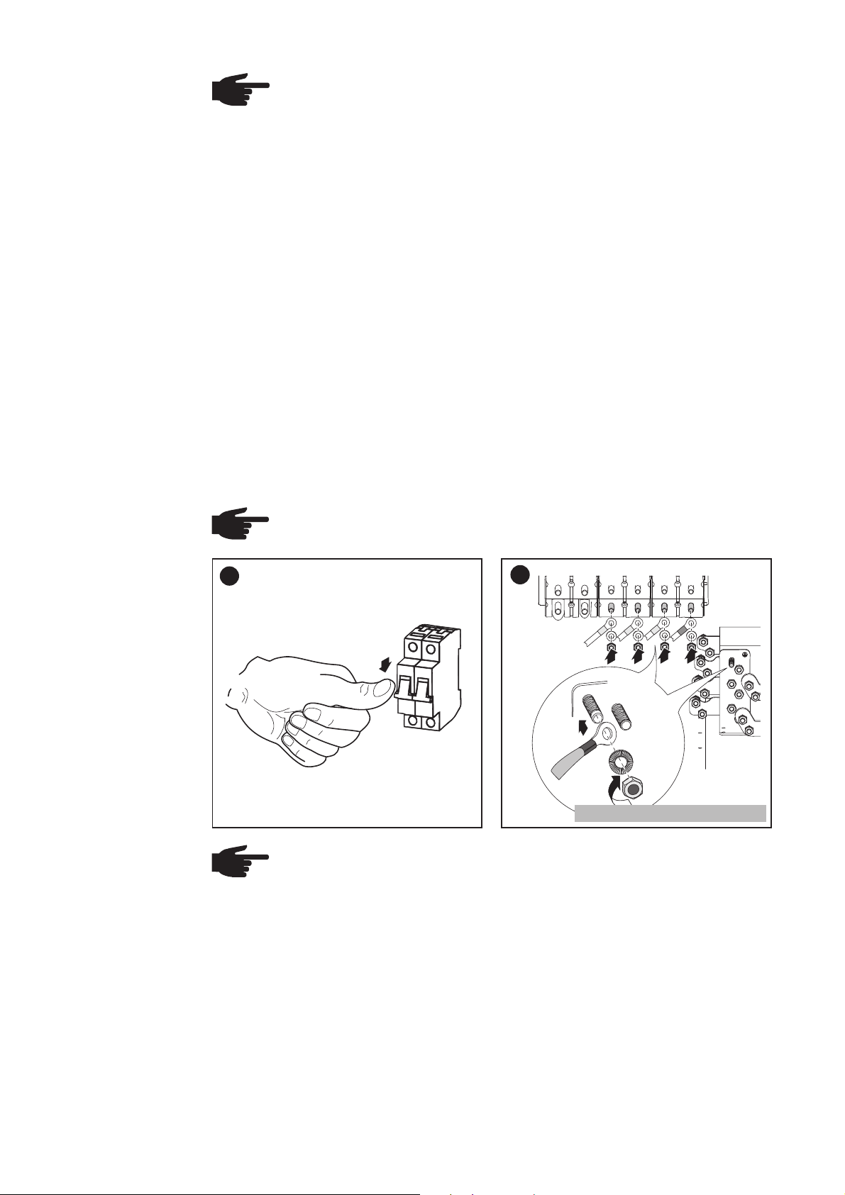
Connecting
aluminium wires
NOTE When connecting aluminium wires::
- observe national and international guidelines regarding the connection of
aluminium wires
- follow the instructions of the wire manufacturer
- check every year that the wires are securely attached in accordance with
the specified torque
- follow the connection requirements listed below
Connection Requirements:
1. Carefully clean off the oxide layer of the stripped end of the cable, e.g., using a
knife.
IMPORTANT Do not use brushes, files or sandpaper. Aluminum particles may get stuck
and can transfer to other cables.
2. After removing the oxide layer of the cable end, rub in an acid- and alkali-free
grease.
3. Then immediately fix it to a cable lug suitable for aluminium wires.
Repeat the steps above whenever the cable is disconnected and then reconnected.
Connecting the
Fronius CL to the
Public Grid (AC)
NOTE The phases should be connected in the proper order: GND, L1, L2, L3
and N.
1
AC
1
OFF
2
L1
DC-DC+
L1
1
Tightening torque: 22.17 ft. lb.
L3
L2
L2
2
NL10
L3
M10
N
N
3
4
PE
NOTE Form a min. 4 in. wire loop using all wires.
35
Page 46

AC Connection
Examples
(3)
(2)
Recommendation for the ACside Overcurrent
Protection
(3)
(2)
(1)
AC connection with single hole cable lug
(3)
(2)
(4)
AC connection with double hole cable lug
(1) single hole cable lug
(2) metric hexagon nut M10, wrench size 17 mm (7/64 in.)
(3) two-part securing washer NL 10, outside diameter 16.6 mm (3/32 in.)
(4) double hole cable lug
NOTE To reduce the risk of fire, connect only to a circuit provided with branch
circuit overcurrent protection in accordance with the National Electrical Code,
ANSI / NFPA 70, at a MAXIMUM of:
Fronius CL Overcurrent Protection
208 V 240 V 277 V
33.3 DELTA 125 A 100 A -
44.4 DELTA 175 A 150 A -
55.5 DELTA 200 A 175 A -
36.0 WYE - - 60 A
48.0 WYE - - 80 A
60.0 WYE - - 90 A
36
Page 47

Connecting DC Wires to the Fronius CL
CAUTION! Danger of damaging the inverter due to improperly connected
wires. Improperly connected wires can cause thermal damage to the
inverter and may cause a fire. When connecting AC and DC wires:
- only use the installation and connection accessories as part of the
shipment
- make sure that all cable connections are properly secured applying
the correct tightening torque.
General Information about Solar
Modules
Safety
In order to select suitable solar modules and get the most efficient use out of the Fronius CL, please note the following points:
- The open circuit voltage of the solar modules increases as the temperature decreases (assuming constant irradiance). The open circuit voltage should never rise
above 600 V regardless of temperature and an irradiance of 1000 W/m².
If the open circuit voltage exceeds 600 volts, the Fronius CL may be damaged, and
all warranty rights will become null and void.
- More exact data for sizing the solar array for the particular location can be obtained
using calculation tools such as the Fronius Configuration Tool (available at http://
www.fronius-usa.com).
- See NEC table 690.7 for the appropriate code-related voltage adjustment factor for
crystalline silicon modules, or use the manufacturer’s specified voltage coefficient.
WARNING! An electrical shock can be fatal. Danger from grid voltage and
DC voltage from solar modules.
- Never work with live wires! Prior to all connection work, make sure that
the AC and DC wires are not charged.
- Only a licensed electrician is permitted to connect this inverter to the
public grid.
- Power stage sets should only be opened by Fronius-trained service
personnel.
WARNING! An electric shock can be fatal. Inadequately sized electrical
components can cause serious injuries to persons and damage to (or loss
of) property.
- All electrical installations must be carried out in accordance with the
National Electrical Code, ANSI/NFPA 70, and any other codes and
regulations applicable to the installation site.
- For installations in Canada, the installations must be done in accordance with applicable Canadian standards.
- Use copper wires for all grounding cables.
- See NEC section 250 for correct grounding.
- Use only solid or stranded wire. Do not use fine stranded wire.
WARNING! An electric shock can be fatal. Normally grounded conductors
may be ungrounded and energized when a ground fault is indicated. The
ground fault has to be repaired before operation is resumed.
37
Page 48

Safety
(continued)
DC Terminals
Two-part securing washers in two sizes
are included with the installation and
radial teeth:
outside
connection accessories.
These two-part securing washers with
cam faces on one side and radial teeth on
the opposite side are pairwise pre-assembled, cam face to cam face.
cam faces:
inside
pairwise
pre-assembled
NOTE If a two-part securing washer is split, make sure that the two parts
are mounted cam face to cam face only!
DC+ DC- L1 L2 L3 N
Connecting
aluminium wires
NOTE When connecting aluminium wires::
- observe national and international guidelines regarding the connection of
aluminium wires
- follow the instructions of the wire manufacturer
- check every year that the wires are securely attached in accordance with
the specified torque
- follow the connection requirements listed below
Connection Requirements:
1. Carefully clean off the oxide layer of the stripped end of the cable, e.g., using a knife.
IMPORTANT Do not use brushes, files or sandpaper. Aluminum particles may get stuck
and can transfer to other cables.
2. After removing the oxide layer of the cable end, rub in an acid- and alkali-free grease.
3. Then immediately fix it to a cable lug suitable for aluminium wires.
Repeat the steps above whenever the cable is disconnected and then reconnected.
38
Page 49

Connecting DC
Wires
NOTE Connecting the DC wiring
with the wrong polarity may
cause damage to the inverter.
Check both the polarity and the
open circuit voltage.
The DC Voltage must not exceed 600 V,
regardless of temperature.
DC Connection
Examples
1
DC+ DC- L1 L2 L3 N
NL12
M12
Tightening torque 22.17 ft. lb.
(3)
(2)
NOTE Form a min. 4 in. wire
loop using all wires.
(3)
(2)
(3)
(2)
(1)
DC connection with single hole cable lug and one
cable
DC connection with double hole cable lug and one
cable
Important When connecting 2 wires make sure that both cable lugs are placed upon
each other upside down.
1
2
39
1
2
(5)
(4)
Page 50

DC Connection
Examples
(continued)
(3)
(2)
(6)
(6)
(3)
(2)
(5)
(1)(1)
(4)
(1)
DC connection with single hole cable lug and three
cables
DC connection with double hole cable lug and three
cables
NOTE When connecting three cables consider an overcurrent protection
according to NEC article 240!
(1) single hole cable lug
(2) metric hexagon nut M12, wrench size 19 mm (3/16 in.)
(3) two-part securing washer NL 12, outside diameter 19.5 mm (13/64 in.)
(4) double hole cable lug
(5) copper ring, diameter 13 and 25 x 9.7 mm (33/64 and 63/64 x 3/8 in.)
(6) copper spacer
(2)
(3)
(5)
(4)
(4)
40
Page 51

Fronius CL Solar Module Ground
General The inverter allows you to ground solar modules via a fuse in the connection area either
at the negative pole or the positive pole.
Solar Module
Ground via Fuse
L
L
L
N
PE
(2)
1
2
3
(1)
(1) Fuse holder for solar module ground at the positive pole
(2) Fuse holder for solar module ground at the negative pole
(1)
DC+
(2)
=
DC-
(3)
~
DC+
DC-
(3)
(2)(1)
=
~
L
L
L
N
PE
1
2
3
Solar Module Ground at Negative Pole (Fuse Holder
for Solar Module Ground at Positive Pole Not Used)
(1) Solar module (2) Inverter (3) Fuse
Depending on the inverter output, Fronius recommends fuses with the following nominal
current values for the solar module ground:
- Fronius CL 33.3 DELTA:2 A
- Fronius CL 44.4 DELTA:2 A
- Fronius CL 55.5 DELTA:3 A
Fuse dimensions: 13/32 x 1 1/2 in. (10 x 38 mm)
41
Solar Module Ground at Positive Pole (Fuse Holder
for Solar Module Ground at Negative Pole Not
Used)
- Fronius CL 36.0 WYE:2 A
- Fronius CL 48.0 WYE:2 A
- Fronius CL 60.0 WYE:3 A
Page 52

Safety
WARNING! An electrical shock can be fatal. Normally grounded conduc-
tors may be ungrounded and energized when a ground fault is indicated.
The ground fault has to be repaired before operation is resumed.
WARNING! An electrical shock can be fatal. Danger from DC voltage from
solar modules.
The DC main switch is only used to switch off power to power stage sets.
When the DC main switch is turned off, any solar module ground installed
remains unaffected. Never touch the DC+ and DC-.
Solar Module
Ground at Negative Pole
Solar Module
Ground at Positive Pole - Inserting Fuse
The Fronius CL is designed for a solar module ground at the negative pole. The inverter
comes supplied with a corresponding fuse in the right fuse holder for a solar module
ground at the negative pole.
The left fuse holder for the solar module ground at the positive pole must have a plastic
bolt inserted.
NOTE Do not connect the ground to the negative DC line at any point! This is
already done within the inverter. If negative DC lines are connected to the DC
terminals or prior to this to the ground, this will circumvent the GFDI protection system, preventing your inverter from properly detecting a fault current.
In addition, turning the DC disconnect to the OFF/open circuit condition will
not disconnect the array from ground, as it only disconnects the DC positive.
The Fronius CL is designed for a solar module ground at the negative pole. For solar
module ground at the positive pole the fuse must be inserted into the corresponding
fuse holder as follows:
1
2
1
Important The right fuse holder for the
solar module ground at the negative pole
must have a plastic bolt inserted.
Inserting the fuse at the positive pole
grounds the solar module.
+
-
4
3
+
-
+
When the solar module is grounded at the positive pole:
NOTE Do not connect the ground to the positive DC line at any point! This is
already done within the inverter. If positive DC lines are connected to the DC
terminals or prior to this to the ground, this will circumvent the GFDI protection system, preventing your inverter from properly detecting a fault current.
In addition, turning the DC disconnect to the OFF/open circuit condition will
not disconnect the array from ground, as it only disconnects the DC negative.
42
Page 53

Inserting Power Stage Sets
Overview A sticker is located in the inverter on the top cover. The sticker provides an overview of
the steps required for inserting power stage sets. A detailed description of the sticker
can be found in ‘Troubleshooting and Maintenance’ in the ‘Replacing Power Stage Sets’
section.
General
One slot in the inverter is assigned to each power stage set rack. In order to avoid
mixing up the slots, positioning bolts are used on the back of the power stage set racks
and a corresponding recess is available for the slot.
Positioning Bolt on the Back of the Power Stage Set
Opening for the Slot
43
Page 54

Slot Arrangement
Dip Switches for
Identifying Power
Stage Set Racks
PS 13PS 12
PS 14
PS 11PS 10PS 09
PS 08PS 07PS 06
PS 05PS 04PS 03
PS 01PS 00
PS 02
A dip switch on the front of the power stage set is used to identify each individual power
stage set in the inverter. The dip switch must be set exactly for each individual slot.
Dip Switch
Settings for Each
Slot
4
ON
3
2
1
Dip Switches on the Front of the Power Stage Set
ON
1
2
ON
1
2
ON
1
2
ON
1
2
ON
1
2
110 0
PS 12
3
4
1001
PS 09
3
4
0110
PS 06
3
4
0011
PS 03
3
4
0000
PS 00
3
4
ON
1
ON
1
ON
1
ON
1
ON
1
110 1
PS 13
3
4
2
1010
PS 10
3
4
2
0111
PS 07
3
4
2
0100
PS 04
3
4
2
0001
PS 01
3
4
2
ON
1
2
ON
1
2
ON
1
2
ON
1
2
ON
1
2
1110
PS 14
3
4
1011
PS 11
3
4
1000
PS 08
3
4
0101
PS 05
3
4
0010
PS 02
3
4
44
Page 55

Inserting Power
Stage Sets
WARNING! An electrical shock can be fatal. Danger from grid voltage and
DC voltage from solar modules.
- The connection area should only be opened by a licensed electrician.
- Never work with live wires! Prior to all connection work, make sure that
the AC and DC wires are not charged.
- DC and AC main switch are only used to switch off power to the power
stage set. When DC and AC main switch are turned off, the connection
area is still energized.
NOTE Check the following before inserting power stage sets into the inverter:
- The location of the positioning bolt
- Whether or not the dip switch is set for the slot
1
sets, the plastic front of the power stage
set must be inserted flat against the side
metal supports.
If a power stage set cannot be inserted
completely into the inverter, then the
power stage set has been inserted into
the wrong slot.
Important When inserting power stage
1
- Insert 4 rails
2
2
1
3
3
8
- Secure rails using 4 x 5 screws
3
3
Tightening torque: 1.84 ft. lb.
3
3
1
45
Page 56

Application
Example
Inserting power stage set PS 10:
1
1
- Insert positioning bolt into no. 10
3
2
4
ON
- Set the dip switch for PS 10 as per
„Dip Switch Settings for Each Slot“:
1 - 0 - 1 - 0
3
2
1
1
- Insert power stage set PS 10 into the
slot for PS 10
PS 13PS 12
PS 01PS 00
PS 14
PS 11PS 10PS 09
PS 08PS 07PS 06
PS 05PS 04PS 03
PS 02
Slot for Power Stage Set PS 10
46
Page 57

Closing the Fronius CL
3
1
2
3
4
Closing the
Fronius CL
CAUTION! An inadequate grounding conductor connection can cause
serious injuries to persons and damage to (or loss of) property. The screws
on the covers provide an adequate grounding conductor connection for the
housing ground and should not under any circumstances be replaced by
other screws that do not provide a proper grounding conductor connection.
1
1
2
3
4
Tightening torque: 1.84 ft. lb.
- Replace covers
- Secure with screws
2
1
1
1
- Close doors
2
- Close door latches
47
Page 58

1
2
Start-up Operation
Factory Pre-set
Configuration
Requirements for
Start-up Operation
Start-up Operation
Your Fronius CL has been pre-configured in the factory and is ready for operation. You
only have to set the available power grid for start-up for the inverters.
To change your inverter settings, please see section ‘The Setup Menu’ in
the chapter ‘Operation.’
- Fronius CL connected to the public grid (AC)
- Fronius CL connected to the solar modules (DC)
- All power stage sets inserted
- Power stage sets secured via rails
- All covers attached
- Doors closed and locked
NOTE Flip the AC main switch and the DC main switch to Position - ON only when:
- the inverter doors are totally closed
- the door latches are totally closed
1. If available, turn on the external AC
disconnect
2. Flip AC main switch on the inverter to
ON
position - ON -
3. Flip DC main switch to position - ON -
ON
As soon as the photovoltaic modules
produce sufficient power, the Operating Status LED lights up orange.
The orange LED indicates that the
feed-in mode of the Fronius CL will
begin shortly.
The screen displays the startup
phase.
- Segment test
All display elements light up for
about one second
- The inverter goes through a
master check list for several
seconds
The display shows ‘TEST’ and
indicates the respective component that is being tested (for
example, ‘LED’)
48
Page 59

Start-up Operation
(continued)
- The grid selection phase begins.
‘SETUPSEL’ is displayed.
4. Press the ‘Enter’ key
The first grid selection option is
shown (e.g., 208 V)
5. Select the public grid
Selecting the
Public Grid
1. Use the ‘Up’ and ‘Down’ keys to select the desired grid:
Grid voltage 208 V Delta
No neutral conductor in the system
Neutral conductor monitoring is deactivated
L1
120 °
208 V
12 0 °
=
L1
120 V
N
208 V
L2L3
~
12 0 °
208 V
120 V
L2
120 °
208 V
120 °
208 V
120 V
L3
208 V
Grid voltage 208 V Delta: 120 V WYE
Neutral conductor available in the system
Neutral conductor monitoring is activated
49
120 °
=
~
Page 60

Selecting the
Public Grid
(continued)
120 °
L1
120 °
240 V
240 V
L2L3
12 0 °
L2
Grid voltage 240 V Delta
No neutral conductor in the system
Neutral conductor monitoring is deactivated
Grid voltage 480 V Delta: 277 V WYE
240 V
12 0 °
=
~
L1
120 °
=
277 V
480V
N
277 V
120 °
480 V
277 V
L3
480 V
Neutral conductor available in the system
Neutral conductor monitoring is activated
~
2. Press the ‘Enter’ key 2x to confirm your grid selection (or use the ‘Esc’ key to return
to grid selection)
Startup Phase
during Startup
Operation
The startup phase restarts with the segment test.
- Segment test
All display elements light up for about
one second
- The Fronius CL goes through a
master check list for several seconds
The display shows ‘TEST’ and indicates the respective component that is
being tested (for example, ‘LED’)
50
Page 61

Startup Phase
during Startup
Operation
(continued)
- ‘TESTCOM’ is shown
- Synchronization with grid:
‘WAITPS’ is displayed, the inverter
icon flashes: The Fronius CL is
waiting for all power stage sets in the
network to be on stand-by. This
procedure takes place dependent on
the DC voltage.
Next, the display shows ‘SYNCAC,’ the
grid icon flashes
- Startup test:
Before the Fronius CL starts feeding
energy into the grid, the conditions of
the grid are tested in detail in accordance with regulations. The display
shows ‘STARTUP’
- Operation of feeding energy into the
grid:
After selecting the grid and when the
tests are concluded, the Fronius CL
starts feeding energy into the grid.
The display shows the present power
feeding into the grid.
The Operating Status LED lights up
green, and the Fronius CL starts
operating.
Important For more information about the startup phase, please see chapter ‘Operation’, section ‘Product Description Fronius CL’ (Startup Phase, Test Procedure).
51
Page 62

Setting inverter
for solar module
ground at the
positive pole
If the inverter will be operated with solar modules that require a solar module ground at
the positive pole, the corresponding grounding method must be set in the ‘Basic Service’ menu.
For accessing the ‘Basic Service’ menu the access code ‘22742’ must be entered.
If solar modules are connected to the inverter that require a solar module ground at the
positive pole, the status message 472 "Ground fault detected" will be displayed after the
inverter is turned on and the startup phase is completed
1. Press the unassigned ‘Menu/Esc’ key
5 x
‘CODE’ is displayed, the first digit
flashes.
2. Enter the access code 22742:
Use the ‘Up’ and ‘Down’ keys to
select the value for the first digit of the
access code
3. Press the ‘Enter’ key
The second digit flashes.
4. Repeat steps 2 and 3 for the second,
third, fourth and fifth digit of the
access code until ...
... the access code flashes.
5. Press the ‘Enter’ key
The inverter is in the ‘Basic Service’
menu, the first parameter ‘MIX
MODE’ is displayed.
52
Page 63

Setting inverter
for solar module
ground at the
positive pole
(continued)
6. Use the ‘Up’ or ‘Down’ keys to select
the 'GNDMODE' parameter
7. Press the ‘Enter’ key
The set grounding mode is displayed.
8. Use the ‘Up’ and ‘Down’ keys to
select the corresponding ‘POS GND’
grounding method:
POS = solar module ground at positive pole
9. Press the ‘Enter’ key to apply the
required grounding mode
10. Press the ‘Esc’ key to exit the Basic
Service menu
53
Page 64

Selecting the Interface Protocol and Setting the Inverter Baud Rate
General
Entering the
access code
If a data communication connection is required between the inverter and other Fronius
data communication components, the ‘Interface protocol’ must be set in the ‘Basic
Service’ menu.
1. Press the ‘Menu’ key
‘Menu’ is shown.
2. Select the ‘Setup’ mode using the
‘Left’ or ‘Right’ keys
3. Press the unoccupied ‘Menu/Esc’ key
5 x
‘CODE’ is displayed, the first digit
flashes.
4. Enter the access code 22742:
Use the ‘Up’ and ‘Down’ keys to
select a value for the first digit of the
access code
5. Press the ‘Enter’ key
The second digit flashes.
6. Repeat steps 4 and 5 for the second,
third, fourth and fifth digit of the
access code until ...
... the access code flashes.
7. Press the ‘Enter’ key
54
Page 65

Entering the
access code
(continued)
The inverter is now in the ‘Basic
Service’ menu, the first parameter
‘MIX MODE’ is displayed.
Selecting the
interface protocol for communication with other
data communication components
The inverter is in the ‘Basic Service’
menu, the first parameter ‘MIX
MODE’ is displayed.
1. Use the ‘Up’ and ‘Down’ keys to
select the ‘COMM’ parameter
2. Press the ‘Enter’ key
‘MODE’ is shown.
3. Press the ‘Enter’ key
55
The set protocol type is displayed.
4. Use the ‘Up’ and ‘Down’ keys to
select the ‘IFP’ protocol type (interface protocol):
5. Press the ‘Enter’ key to apply the ‘IFP’
protocol type.
Page 66

Selecting the
interface protocol for communication with other
data communication components
(continued)
The ‘IFP’ protocol type is applied,
‘MODE’ is displayed.
For setting the inverter baud rate
without exiting the ‘Basic Service’
menu follow the steps in the enclosed
section ‘Setting the Inverter baud
rate’, starting from step 3.
6. Press the ‘Esc’ key 2 x to exit the
‘Basic Service’ menu
Setting the
inverter baud
rate
The inverter is in the ‘Basic Service’
menu, the first parameter ‘MIX
MODE’ is displayed.
1. Use the ‘Up’ and ‘Down’ keys to
select the ‘COMM’ parameter
2. Press the ‘Enter’ key
MODE’ is shown.
56
3. Use the ‘Up’ and ‘Down’ keys to
select the ‘IFP’ parameter
4. Press the ‘Enter’ key
‘BAUD’ is displayed
5. Press the ‘Enter’ key
Page 67
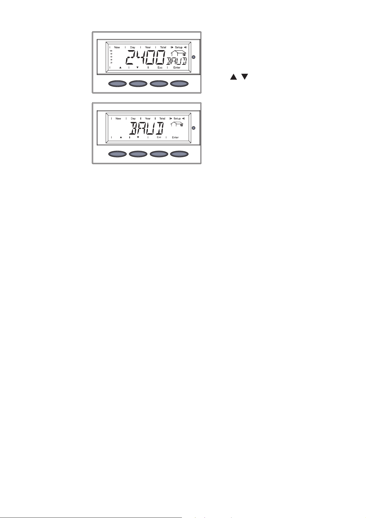
Setting the
inverter baud
rate
(continued)
The set baud rate is displayed.
6. Use the ‘Up’ and ‘Down’ keys to
select the desired baud rate: 2400 /
4800 / 9600 / 14400 / 19200
7. Press the ‘Enter’ key
The selected baud rate is applied,
‘BAUD’ is displayed.
8. Press the ‘Esc’ key 3 x to exit the
‘Basic Service’ menu
The inverter begins the startup phase after exiting the ‘Basic Service’ menu.
57
Page 68

Setting the Relay Contact Functions
General According to the assigned relay contact functions the isolated relay contacts at the
inverter’s connection area can be used for several tasks, e.g.:
- connecting and controlling external ventilation
- giving out an acoustic or visual signal
Possible Functions of Relay
Contacts
Function
number
Activation criterion
for the switch con-
1)
tact
1
2
--
Power feed-in possible
on DC side
3
4
Cabinet fan in operati-onCabinet fan not in
Max. interior temperature >/= 104 °F
5 Max. interior temperatu-
re >/= 122 °F
6
Triggering of continual3) and temporary4)
service codes
Deactivation criterion2) for the switch
contact
Power feed-in not
possible on DC side
operation
Max. interior temperature </= 86 °F
Max. interior temperature </= 104 °F
Error confirmation per
key press / per Solar
Net command
Description
not available on US
devices
Shut-down of external
components over night
(e.g., 60 Hz transformer)
External ventilation / air
conditioning can be
activated
Status display /
Relay contact trips
7
Triggering of continual4) service codes
Error confirmation per
key press / per Solar
Status display /
Relay contact trips
Net command
8
1)
Activation = switch contact closes / opens
2)
Deactivation = switch contact opens / closes
3)
Continual service codes (e.g., for an inverter malfunction or shutdown, when the
Inverter in feed-in
mode
Inverter not in feed-in
mode
Control of motorized
stop valve
service code is displayed longer than 4 h 15 min.)
4)
Temporary service codes (e.g., brief interruption of feed-in operation, a service
code is triggered more than 50 x per day)
58
Page 69

Entering the
access code
The ‘Relay contact functions’ must be set in the ‘Basic Service’ menu.
1. Press the ‘Menu’ key
‘Menu’ is shown.
2. Select the ‘Setup’ mode using the
‘Left’ or ‘Right’ keys
3. Press the unoccupied ‘Menu/Esc’ key
5 x
‘CODE’ is displayed, the first digit
flashes.
4. Enter the access code 22742:
Use the ‘Up’ and ‘Down’ keys to
select a value for the first digit of the
access code
5. Press the ‘Enter’ key
The second digit flashes.
6. Repeat steps 4 and 5 for the second,
third, fourth and fifth digit of the
access code until ...
... the access code flashes.
7. Press the ‘Enter’ key
59
The inverter is now in the ‘Basic
Service’ menu, the first parameter
‘MIX MODE’ is displayed.
Page 70

Setting the relay
contact functions
The inverter is in the ‘Basic Service’
menu, the first parameter ‘MIX
MODE’ is displayed.
1. Use the ‘Up’ and ‘Down’ keys to
select the ‘GPSC CFG’ parameter
2. Press the ‘Enter’ key
‘SC1’ is shown.
3. Use the ‘Up’ and ‘Down’ keys to
select the relay contact:
SC1 = relay contact 1
SC2 = relay contact 2
4. Press the ‘Enter’ key
The set relay contact function is
displayed, the digit flashes.
5. Use the ‘Up’ and ‘Down’ keys to
select a value from 2 - 8 for the relay
contact function as per section
“Possible Functions of Relay Contacts“
6. Press the ‘Enter’ key
The selected relay contact function is
applied, the presently set relay
contact is shown, e.g. ‘SC1’.
7. Press the ‘Esc’ key 3 x to exit the
‘Basic Service’ menu
60
Page 71

1
1
2
Inserting Option Cards
2
Safety
WARNING! An electrical shock can be fatal. Danger from grid voltage and
DC voltage from solar modules.
- Never work with live wires! Prior to all connection and maintenance
work, make sure that the AC and DC wires are not charged.
- The connection area should only be opened by a licensed electrician.
- Power stage sets should only be opened by Fronius-trained service
personnel.
- All electrical installations must be in accordance with the National
Electrical Code, ANSI/NFPA 70, and any other codes and regulations
applicable to the installation site.
- For installations in Canada, the installations must be done in accordance with applicable Canadian standards.
WARNING! An electrical shock can be fatal. Danger from residual voltage
from capacitors.
You must wait until the capacitors have discharged. Discharge takes 5
minutes.
NOTE Follow general ESD precautions when handling option cards.
Opening the
Fronius CL
When adding option cards to the Fronius CL, please follow all inverter safety instructions and information.
1
2
OFF
OFF
3
4
CAUTION! An inadequate grounding conductor connection can cause
serious injuries to persons and damage to (or loss of) property. The screws
on the covers provide an adequate grounding conductor connection for the
housing ground and should not under any circumstances be replaced by
other screws that do not provide a proper grounding conductor connection.
61
Page 72

Opening the
Fronius CL
(continued)
3
1
2
4
1
2
3
Inserting Option
Cards
Connecting
Option Cards,
Laying Data
Communication
Wires
1
1
2
secure.
CAUTION! Danger of short circuit by loose metal parts from knockouts.
Loose metal parts in the inverter may cause short circuits when the inverter
is powered up. When removing knockouts, make sure that
- no loose metal parts fall into the inverter
- any metal pieces that do fall into the inverter are removed immediately
- Insert option cards into free slots and
- Remove strain-relief device
1
3
2
1
54
5
62
- Remove the knockouts
Page 73

Connecting
Option Cards,
Laying Data
Communication
Wires
(continued)
Only when data communication cables run into the inverter from the side:
Important Use a suitable tool to break out the wire input openings corresponding to the
diameter of the data communication cables from the side of the mounting base. Follow
all safety instructions from the tool manufacturer.
NOTE Only use water tight conduit fittings and conduits for inverter cabling.
Conduit fittings and conduits are not included with the inverter.
1
4
3
5
2
6
1
2
5
4
3
1
2
Conduit
NOTE To prevent damage to the data communication cables from the rough
edges of wire input openings, install a suitable edge guard in the knockout
and wire input opening on the side of the mounting base (e.g., a rubber
bushing).
3
4
1
5
2
3
3
4
1
6
Tightening torque: 1.48 ft. lb.
1
3
2
4
63
Page 74

3
1
2
3
4
Closing the
Fronius CL
CAUTION! An inadequate grounding conductor connection can cause
serious injuries to persons and damage to (or loss of) property. The screws
on the covers provide an adequate grounding conductor connection for the
housing ground and should not under any circumstances be replaced by
other screws that do not provide a proper grounding conductor connection.
1
3
Tightening torque: 1.84 ft. lb.
- Replace right cover
- Secure with screws
2
1
2
1
1
- Close doors
2
- Close door latches
64
Page 75

Solar Net and Data Communication
Solar Net Fronius developed Solar Net to make these add-on system components flexible and
capable of being used in a wide variety of different applications. Solar Net is a data
network that enables several inverters to be linked with the data communications
components.
Solar Net is a bus system. A single cable is all that is required for one or more inverters
to communicate with all data communications components.
Data Communication
The core of Solar Net and thus data communication is the Fronius Datalogger. It
coordinates data transmissions and ensures that even large volumes of data are
distributed and stored quickly and securely.
The ‘Fronius Com Card’ is used to integrate an inverter into Solar Net.
Important Each inverter that is to be monitored using a Fronius Datalogger requires a
‘Fronius Com Card.’ In this case, the ‘Fronius Com Card’ serves as a link between the
internal network of the inverter and the Solar Net interface of the Fronius Datalogger.
Important Each inverter can only have one ‘Fronius Com Card.’ A network may only
contain one Fronius Datalogger.
The first inverter with a ‘Fronius Com Card’ can be positioned up to 3281. ft. (1000 m)
away from the last inverter or component.
Different data communications components are detected automatically by Solar Net.
In order to distinguish among several identical data communications components, each
one must be assigned a unique number.
In order to uniquely identify each inverter in Solar Net,
each inverter must also be assigned an individual number.
You can assign individual numbers as per ‘The Setup Menu’ section in these operating
instructions.
More detailed information on the individual data communication component can be
found in the relevant operating instructions or online at http://www.fronius-usa.com.
65
Page 76

Application
Example
Logging and archiving data from the inverter and sensor using a Fronius Datalogger
and Sensor Box:
Fronius
CL
12 3
Com Card
IN OUT
Fronius
CL
PC
Com Card
Datalogger C.
IN OUT
RS 232
Sensor Box
IN OUT
°C
W/m²
m/s
Fronius
CL
IN
Com Card
OUT
Termination plug
Data network with 3 Fronius CL units and one Sensor Box:
- all Fronius CL units have one ‘Fronius Com Card’
- one Fronius CL has a ‘Fronius Datalogger card’ (no. 2)
- Fronius Datalogger has two RS-232 interfaces for connecting to a PC and a modem
Option cards communicate within the inverter via its internal network. External communication (Solar Net) takes place via ‘Fronius Com Cards.’ Each ‘Fronius Com Card’ is
equipped with two RS485 interfaces - an input and an output. RJ45 plug connectors are
used to connect to these cards.
66
Page 77

Keys and Symbols
Keys and Symbols
(1)
Keys and Symbols on the Inverter
Item Function
(1) Display
for displaying values, settings and menus
(2) Operating Status LED
for displaying the operating status
(3) ‘Enter’ key
for confirming a selection
(4) ‘Menu / Esc’ key
for changing the menu level
for exiting the Setup menu
(2)
(3)(4)(5)(6)
(5) ‘Down/Right’ key
depending on the selection:
for navigating down
for navigating right
(6) ‘Left/Up’ key
depending on the selection:
for navigating left
for navigating up
Display Power for the display comes from the solar modules via safety-low voltage. Therefore,
the display is available only during daylight hours.
Important The inverter display is not a calibrated measuring instrument. A slight deviation of a few percentage points is intrinsic to the system. A calibrated meter is required to
make calculations for the utility company.
67
Page 78

Display
(continued)
(1) (2) (3) (4) (5)
(13)
(12)
Display
Item Function
(1) Icons for the ‘Now’ display mode
(2) Icons for the ‘Day’ display mode
(3) Icons for the ‘Year’ display mode
(4) Icons for the ‘Total’ display mode
(5) Icons for the ‘Setup’ display mode
(6) Icons for operating conditions
Indicates the maximum value within the period of observation (depending on the display mode chosen)
(6)
(7)
(8)(9)(10)(11)
Indicates the minimum value within the period of observation (depending on the display mode chosen)
Important The min. and max. values may not correspond to the
absolute extreme values, as the measured data are recorded at two
second intervals.
... appears with data readings that are directly related to the solar
modules
... appears with AC data readings that are directly related to the grid
... appears with data readings that are directly related to the inverter
(7) Area for display unit
for displaying the applicable measuring unit
(8) Icon for the ‘Enter’ key
(9) Icons for the ‘Menu/Esc’ key
(10) Icons for the ‘Down/Right’ key
(11) Icons for the ‘Left/Up’ key
(12) Area for data
for displaying the data value measured
(13) Output bar (not active during setup settings)
indicates the output power at a given moment - independent from the display
mode chosen. The screen displays % of the maximum possible output power of
your solar inverter.
68
Page 79

Operating Status
LED
Depending on the operating status, the
Operating Status LED assumes different
colors:
Position of Operating Status LED on the Inverter
Operating Status LEDExplanation
lights up green A green light starts as soon as the inverter has completed the
startup phase, and stays green as long as the operation of
feeding power into the grid continues.
It indicates problem-free operation of the photovoltaic equipment.
flashes green The photovoltaic equipment is operating without fault, an
additional message is shown on the screen.
When a status code is shown, rectify the relevant condition by
going to the ‘Maintenance and Service’ chapter, ‘Status Diagnosis
and Troubleshooting’ section. The status message can be acknowledged by pressing the ‘Enter’ key.
lights up orange The inverter will enter the automatic startup phase as soon as the
photovoltaic modules yield sufficient power output
flashes orange when a warning is shown on the screen
or
the inverter has been set to standby operation in the setup menu
(manual shutoff of operation).
The next day, operation will resume automatically.
During the time the LED flashes orange, the operation can be
resumed manually at any time (see section ‘The Setup Menu’)
lights up red General status: the respective status code is shown on the
screen
remains dark There is no connection to the solar modules
no power output from modules due to darkness
A list of most status codes, the corresponding status information, their status causes
and repair measures can be found in the chapter ‘Troubleshooting and Maintenance’,
section ‘Status Diagnosis and Troubleshooting’.
69
Page 80

Startup Phase and Grid Feed-in Mode
Startup Phase
Test Procedure
The Fronius CL carries out a self test after being turned on automatically. Then a test of
the public grid is carried out.
This test takes five minutes. During the startup sequence the illumination of the Operating Status LED is yellow.
1. Segment test
All display elements light up for about
one second.
2. Self test of essential inverter components
- The inverter goes through a
master check list for several
seconds
- The display shows ‘TEST’ and
indicates the respective component that is being tested (for
example, ‘LED’)
3. Synchronization with grid
- ‘WAITPS’ is displayed, the inverter
icon flashes: The inverter is
waiting for all power stage sets in
the network to be on stand-by.
This procedure takes place
dependent on the DC voltage.
- Next, the display shows
‘SYNCAC,’ the grid icon flashes.
4. Startup test
- Before the inverter starts feeding
energy into the grid, the conditions of the grid are tested in
accordance with local regulations.
- The display shows ‘STARTUP.’
The startup test takes five minutes.
The time elapsed is indicated by a bar
shrinking from the top down.
Whenever two scale divisions stop
flashing and disappear, 1/10 of the
total duration of the test is over.
70
Page 81

Operation of
Feeding Energy
into the Grid
- After the tests are completed, the inverter starts feeding energy into the grid.
- The display shows the present power feeding into the grid.
- The Operating Status LED lights up green, and the inverter starts operating.
71
Page 82

Navigation in the Menu Level
Activating Display Backlight
Automatic Deactivation of Display
Illumination /
Switching to the
‘Now’ Display
Mode
Accessing Menu
Levels
1. Press any key
The display backlight is activated.
If no key is pressed for 30 seconds or more, the display backlight will go off again.
The setup menu also offers a choice between a permanently lit or permanently dark
display.
If no key is pressed for 2 minutes,
- While power is being fed into the grid, the inverter automatically switches to the
"Now" display mode and the present output power is displayed.
- If the inverter is not feeding power into the grid, the inverter automatically switches
to the startup phase for synchronization with the grid.
The inverter switches to the "Now" display mode or startup phase from anywhere within
the display modes or the Setup menu.
1. Press the ‘Menu’ key (1)
Accessing Menu Levels
Menu Levels
(1)
‘Menu’ appears on the display.
The inverter is now in the menu level.
From the menu level you can
- set the desired display mode
- access the Setup menu
72
Page 83

Display Modes
Display Modes
Selecting a
Display Mode
The following display modes are available for the inverter:
‘Now’ display mode ............. shows present time data
‘Day’ display mode ..............shows data for a period when DC power is present
‘Year’ display mode ............. shows data for the present calendar year - only available in
combination with optional Fronius Datalogger
‘Total’ display mode ............. shows data since your inverter first started operating
1. Access the menu level
(1) (2) (3) (4)
2. Use the ‘left’ (7) or ‘right’ (6) keys to
select your preferred display mode (1)
- (4)
3. Press ‘Enter’ (5)
Selecting a Display Mode
Example: ‘Day’ Display Mode
(5)(6)(7)
The selected display mode is shown.
73
Page 84

Overview of
Display Values
Display Icon Unit Optional Display value
mode
‘Now’ W - output power
V - AC grid voltage
A - output current
Hz - Grid frequency
V - DC array voltage
A - Module current
MOhm - insulation resistance
HH:MM x Time
° F - Supply air temperature
rpm - Speed of left fan
rpm - Speed of right fan
‘Day’ kWh / MWh - Energy supplied
‘Year’
‘Total’
Currency - Yield
lb / T - CO2 reduction
W - Maximum output power
V - Maximum grid voltage
V - Minimum grid voltage
V - Maximum array voltage
HH:MM - Operating hours of the inverter
x Option
If the DatCom component for the required options is not available, the message
‘N.A.’ (not available) is shown.
74
Page 85

Display Values in the ‘Now’ Display Mode
Selecting the
‘Now’ Display
Mode
Display Values in
the ‘Now’ Display
Mode
1. Select the ‘Now’ display mode
The first display value appears in the
‘Now’ display mode.
2. Use the ‘Down’ (2) key to scroll to the
next display value
Scroll back using the ‘Up’ key (1)
(1) (2)
First Display Values in the ‘Now’ Display Mode
Output power
power supplied to the grid at the particular
moment (Watts)
For Example, Phase Voltage for Phase L1
AC grid voltage
External conductor voltage (Volts)
- The phase voltage can be displayed
by pressing the ‘Enter’ key.
- The phase voltage of the other
phases can be displayed by pressing
the ‘Up’ and ‘Down’ keys.
- You can return to the menu level by
pressing the ‘Menu’ key.
Output current
current supplied to the grid at the particular moment (Amperes)
75
Page 86

Display Values in
the ‘Now’ Display
Mode
(continued)
For Example, Phase Current for Phase L3 (WYE)
For Example, Power Stage Set Current for Power
Stage Set G1 (DELTA)
- You can display the phase current for
WYE devices and the current of
individual power stage sets for DELTA
devices by pressing the ‘Enter’ key.
- You can display the phase current of
other phases for WYE devices and
the current of other power stage sets
for DELTA devices by pressing the
‘Up’ and ‘Down’ keys.
- You can return to the menu level by
pressing the ‘Menu’ key.
Grid frequency
(Hertz)
DC array voltage
voltage of the solar array at the moment of
data display (Volts)
The voltage shown while AC power is supplied is called MPP voltage (MPP = maximum
power point).
Module current
current supplied by solar array at the
moment of data display (Amperes)
GFDI status
If there is no ground fault in the system,
‘GFDIOK’ is displayed
NL-MON Communication
When there is communication with the
‘NL-MON’ plug-in card, ‘NLMONOK’ is
displayed.
Time of day (optional Fronius Datalogger)
When the time on the inverter or on a
dataloggere is changed, this changes the
time on all devices connected via Solar
Net.
76
Page 87

Display Values in
the ‘Now’ Display
Mode
(continued)
Supply air temperature
Temperature of the supply air used to cool
the inverter (° F)
The area for unit display switches
between ‘°F’ and ‘AMB.’
Speed of left fan - FAN 1
(rpm - revolutions per minute)
The area for unit display switches
between ‘RPM’ and ‘FAN1.’
Options
Speed of right fan - FAN 2
(rpm - revolutions per minute)
The area for unit display switches
between ‘RPM’ and ‘FAN2.’
If the DatCom component for the required options are not available, the message ‘N.A.’
(not available) is shown.
77
Page 88

Display Values in the ‘Day / Year / Total’ Display Modes
General
Selecting ‘Day /
Year / Total’
Display Modes
For the inverter, the day begins when it switches on. If the DC supply line is disconnected and no Fronius Datalogger is connected, the following parameters within the
display mode ‘Day’ will be re-set after repeating the start-up:
- yield (currency can be selected)
-CO2 reduction (lbs.)
- maximum output power (Watts)
- maximum grid voltage (Volts)
If an optional Fronius Datalogger is available, the display values listed always apply to
the whole day.
- minimum grid voltage (Volts)
- energy supplied (kWh)
- operating hours of the inverter
(1) (2)
First Display Value in the ‘Day’ Display Mode
(1) (2)
First Display Value in the ‘Total’ Display Mode
Important The ‘Year’ display mode is only supported when the Fronius Datalogger
option is installed. This data communications component includes a real-time clock.
First Display Value in the ‘Year’ Display Mode
1. Selecting ‘Day / Year / Total’ Display
2. Use the ‘Down’ (2) key to scroll to the
(1) (2)
Modes
The First Display Value in the ‘Day /
Year / Total’ Display Mode is Shown.
next display value
Scroll back using the ‘Up’ key (1)
78
Page 89

Display Values in
the ‘Day / Year /
Total’ Display
Modes
Energy supplied
Energy supplied during the monitored
period (kWh / MWh)
Due to the variety of different monitoring systems, there can be deviations between the
readings of other metering instruments as compared to the readings from the inverter.
For determining the energy supplied to the grid, only the readings of the calibrated
meter supplied by the electric utility company are relevant.
Yield
Money earned during the monitored
period (set currency and price per kWh in
setup menu)
As was the case for the energy supplied, readings may differ from those of other instruments.
‘The Setup Menu’ section describes how to set the currency and rate for the energy
supplied. The factory setting depends on the respective country-specific setting.
CO2 reduction
CO2 emissions saved during the monitored period
(lb or T, pounds or tons)
The area for unit display switches between ‘lb,’ ‘T’ and ‘CO2.’
The CO2 meter gives an indication of CO2 emissions that would be released during the
generation of the same amount of electricity in a combustion power plant.
This is set for 1.3 lb/kWh in the factory
Maximum output power
Highest output power during observation
period (watts)
Maximum grid voltage
Highest reading of grid voltage (V) during
observation period
Minimum grid voltage
Lowest reading of grid voltage (V) during
observation period
79
Page 90

Display Values in
the ‘Day / Year /
Total’ Display
Modes
Maximum array voltage
Highest reading of array voltage (V)
during observation period
(continued)
Operating hours
Indicates how long the inverter has been
operating (HH:MM)
Duration of operation is shown in hours and minutes up to 999 h and 59 min (display:
‘999:59’). After that only full hours are displayed.
Although the inverter does not operate during the night, all sensor data are recorded
around the clock.
Options If the DatCom component for the required options is not available, the message ‘N.A.’
(not available) is shown.
80
Page 91

The Setup Menu
Default Settings
Accessing the
Setup Menu
The inverter is designed for fully automatic operation. No manual control is necessary
for feeding the power it generates into the grid.
The Setup menu enables you to easily customize the inverter’s preset parameters to
your needs.
1. Switch to the menu level (press the
(1)
(2)(3)(4)
‘Menu’ key)
2. Select the ‘Setup’ (1) mode using the
‘Left’ (4) or ‘Right’ (3) keys
3. Press ‘Enter’ (2)
‘Setup’ Mode Selected in the Menu Level
‘STANDBY’ Menu Item
The Setup menu’s first menu item
‘STANDBY’ is shown.
81
Page 92

Scrolling through
Menu Items
(1) (2) (1) (2)
Menu Items in
the Setup Menu
Example: ‘STANDBY’ Menu Item
Example: ‘CONTRAST’ Menu Item
1. Access the setup menu
2. Scroll through the available menu items using the ‘Up’ (1) and ‘Down’ (2) keys
STANDBY
Manual activation / deactivation of Standby operation using the ‘Enter’ key
Unit Setting range Enter
Factory setting ‘Standby’ deactivated
- During standby operation the electronic system of the power stage is switched off.
No power is fed into the grid.
- The Operating Status LED flashes orange.
- The orange flashing Operating Status LED stops at dusk.
- After the subsequent sunrise, the power supply operation into the grid is resumed
automatically (after completion of the startup phase the LED is illuminated green).
- Grid supply operation can be resumed at any time whenever the LED is flashing
orange (deactivate ‘STANDBY’)
CONTRAST
set contrast on LCD display
Unit Setting range 0 - 7
Factory setting 7
Since contrast depends on temperature, it may be necessary to adjust the menu item
‘Contrast’ when ambient conditions change
82
Page 93

Menu Items in
the Setup Menu
(continued)
LIGHTMODE
default setting of display backlight
Unit Setting range AUTO / ON / OFF
Factory setting AUTO
AUTO: The display backlight will stop 2 minutes after the last key has
been pressed.
ON: The display will remain illuminated whenever power is supplied
to the grid
OFF: The display backlight will be permanently off.
Important The ‘Light Mode’ menu item only applies to the display backlight. The LCD
display will still remain on during operation. Its energy consumption is less than one mW
(1/1000 W).
CASH
setting of currency and rate for invoicing
the energy supplied
Unit Setting range Currency / Charge rate/kWh
Factory setting USD
CO
2
CO2 reduction factor setting
Unit lb/kWh
Setting range 00.01 - 99.99
Factory setting 1.3
YIELD
Setting of
- an OFFSET value for the Total energy
display
- a measurement correction value for
the Day, Year and Total energy
display
Unit Setting range OFFSET / CALI.
Factory setting -
OFFSET Preset value for the energy supplied, added to the actual energy
supplied (e.g., transfer value at the exchange of the inverter)
Setting range: 5 digits + SI prefix (k..., M...)
CALI. Preset correction value, so that the data shown on the inverter
display corresponds to the calibrated data shown on the electric
meter
Setting range: -5.0 - +5.0 % in increments of 0.1
83
Page 94

Menu Items in
the Setup Menu
(continued)
IG-NR
Number (address) setting for the inverter
in a setup comprising multiple inverters
linked together
Unit Setting range 01 - 99 (100th inverter = 00)
Factory setting 01
Important Each inverter must be assigned its own address when using multiple inverters in a data communications system.
DATCOM
indicates status of data transmission,
activates the Signal Card, resets the
Personal Display Card and Interface Card
Unit Display range OKCOM / ERRORCOM / IFP
Testing range SIGCDTEST / SIGCDNI, PDCDRST / PDCDNI, IFCDRST / IFCDNI,
TAC
Factory setting -
OKCOM Data connection available
ERRORCOM Data connection faulty or DATCOM is not installed
IFP Data transmission via interface protocol selected
SIGCDTEST Function test for the Fronius Signal Card option *)
SIGCDNI Fronius Signal Card not installed
PDCDRST Reset Fronius Personal Display Card
PDCDNI Fronius Personal Display Card not installed
IFCDRST Reset Fronius Interface Card
IFCDNI Fronius Interface Card not installed
TAC ON Function test for the Fronius Power Relay Card (TAC) option *)
*) The Fronius Signal Card and Fronius Power Relay Card
(TAC) options are not available for the Fronius CL.
These functions were implemented without additional
option cards on the "Snowball" PC board (fan controller)
via the potential-free relays.
84
Page 95

Menu Items in
the Setup Menu
(continued)
TIME
setting of date and time
Unit DDMMYYYY, HH:MM
Setting range Date / Time
Factory setting -
The ‘Time’ menu item is only supported when the Fronius Datalogger option is installed.
STATEFAN
fan status indicator
Unit Display area N.I.FAN / SAFETYX and STOPX / SELF and TEST / O.K.FAN
Factory setting -
N.I.FAN No communication between the inverter control unit (IG Brain)
and the fan controller (Snowball)
SAFETYX and Fans are stopped for safety reasons;
STOPx ‘x’ describes the error:
0 ... general error (over-temperature, overcurrent)
1 ... left fan malfunction
2 ... right fan malfunction
3 ... left and right fan malfunction
4 ... fan in connection area malfunction
5 ... left fan and fan in connection area malfunction
6 ... right fan and fan in connection area malfunction
7 ... all 3 fans malfunction
SELF and TEST Running a self test
O.K.FAN Fans are OK and operating normally
When there is a communication connection and no self test has been run, you can
trigger the fan controller self test by pressing the ‘Enter’ key.
- ‘TEST’ is displayed after pressing the ‘Enter’ key.
- Repressing ‘Enter’ triggers the fan controller self test. The display then switches
back to the ‘STATEFAN’ menu item.
STATEPS
Status display of power stage sets PS00 max. PS14, the last error that has occurred can be displayed.
Important State 306 (Power Low) and 307 (DC-Low) appear naturally every morning
and evening due to low solar irradiance. These status messages are not the result of a
fault.
85
Page 96

Menu Items in
the Setup Menu
(continued)
VERSION
displays the version number and serial
number of the electronic components
(e.g., IG-Brain, power stage sets, display)
Unit Display area MAINCTRL / LCD / PS (PS00, PS01 ... PS14) /
SNOWBALL
Factory setting -
MAINCTRL Version information of the IG-Brain unit (inverter controller)
LCD Version information of the display
PS Version information of the power stage sets (PS00 - PS14)
SNOWBALL Version information of the Snowball PC board (controls the fan
among other things)
86
Page 97

Setting and Displaying Menu Items
General Menu
Item Settings
Exiting a Menu
Item
1. Access the Setup menu
2. Use the ‘Up’ and ‘Down’ keys to select the desired menu item
3. Press the ‘Enter’ key
4. Use the ‘Up’ and ‘Down’ keys to change the value of the menu item
To save the changed values:
5. Press the ‘Enter’ key
- the changed values are saved in the menu item
- the presently selected menu item is shown
To not save the changed values:
5. Press the ‘Esc’ key
- the changed values are not saved in the menu item
- the presently selected menu item is shown
1. To exit a menu item, press the ‘Menu / Esc’ key
The menu level is displayed:
Setting Standby
Mode - Manual
Shutoff of Feeding Energy into
the Grid
If no key is pressed for 2 minutes,
- the inverter switches to the ‘Now’ display mode from anywhere within the
Setup menu
- the display illumination turns off
- the present output power is displayed
1. Select the ‘Standby’ menu item
2. Press the ‘Enter’ key
87
Page 98

Setting Standby
Mode - Manual
Shutoff of Feeding Energy into
the Grid
(continued)
The display switches between ...
‘STANDBY’
and ...
‘ENTER’
The Standby mode is now activated
(manual shutoff of feeding energy into
the grid).
The Operating Status LED lights up
orange.
Restoring the
Grid Feed
Setting the
Display Contrast
1. Select the ‘Standby’ menu item
2. Press the ‘Enter’ key
The inverter switches to the Startup
phase.
After a successful startup, the Operating Status LED will be green. The
present power feed will be displayed.
1. Select the ‘CONTRAST’ menu item
2. Press the ‘Enter’ key
88
Setting ‘7’ for maximum possible
contrast is shown.
Page 99

Setting the
Display Contrast
(continued)
3. Use the ‘Up’ and ‘Down’ keys to
select the desired level of contrast
Setting ‘0’ for the minimum possible
contrast
4. Press the ‘Enter’ key to accept the
setting
The set contrast is applied. The
‘Contrast’ menu item is displayed.
Setting the
Display Illumination
1. Select the ‘LIGHTMODE’ menu item
2. Press the ‘Enter’ key
The ‘AUTO’ setting is shown.
3. Use the ‘Up’ and ‘Down’ keys to
select the desired setting for the
display illumination
4. Press the ‘Enter’ key to accept the
setting
The display illumination setting is
applied. The ‘LIGHTMODE’ menu item
is displayed.
89
Page 100

Setting the
Currency and
Rate
1. Select the ‘CASH’ menu item
2. Press the ‘Enter’ key
The currency is shown
Factory setting = ‘USD’
The first of 3 characters flashes.
3. Use the ‘Up’ and ‘Down’ keys to
select a letter for the first character
4. Press the ‘Enter’ key
The second digit flashes.
5. Repeat steps 3 and 4 for the second
and third characters until ...
The set currency flashes.
6. Press the ‘Enter’ key
The currency is applied. The charge
rate is displayed in kWh/currency
factory setting = 0.14 USD / kWh
The first digit flashes.
7. Use the ‘Up’ and ‘Down’ keys to
select a value for the first digit (e.g.,
0)
8. Press the ‘Enter’ key
The second digit flashes.
9. Repeat steps 7 and 8 for the first,
second and third digit after the decimal point until ...
90
 Loading...