

Page 1

/ Perfect Charging / Perfect Welding / Solar Energy
Fronius CL
36.0 / 48.0 / 60.0
Operating Instructions
Inverter for grid-connected photo-
EN-US
voltaic systems
42,0426,0077,EA 010-31032015
Page 2

0
Page 3

Dear reader,
Introduction Thank you for the trust you have placed in our company and congratulations on buying this
high-quality Fronius product. These instructions will help you familiarize yourself with the
product. Reading the instructions carefully will enable you to learn about the many different
features it has to offer. This will allow you to make full use of its advantages.
Please also note the safety rules to ensure greater safety when using the product. Careful
handling of the product will repay you with years of safe and reliable operation. These are
essential prerequisites for excellent results.
EN-US
1
Page 4

2
Page 5

Contents
Safety rules ................................................................................................................................................ 7
General Information 11
Protection of Persons and Equipment ....................................................................................................... 13
Safety.................................................................................................................................................... 13
Protection of Persons and Equipment .................................................................................................. 13
Galvanic isolation.................................................................................................................................. 13
Monitoring the grid ................................................................................................................................ 13
Warning notices affixed to the device ................................................................................................... 14
Utilization in accordance with "intended purpose" ..................................................................................... 16
Utilization in accordance with "intended purpose" ................................................................................ 16
Field of application ............................................................................................................................... 16
Photovoltaic system stipulations ........................................................................................................... 16
Functional principle .................................................................................................................................... 17
Functional principle ............................................................................................................................... 17
The MIXTM concept............................................................................................................................. 17
Reliability............................................................................................................................................... 17
Forced ventilation.................................................................................................................................. 18
Power derating...................................................................................................................................... 18
Solar module ground............................................................................................................................. 18
The Fronius CL unit in the PV system ....................................................................................................... 19
General ................................................................................................................................................. 19
Tasks .................................................................................................................................................... 19
Converting DC to AC Current ............................................................................................................... 19
Display function and data communication ............................................................................................ 19
System upgrades ....................................................................................................................................... 20
System upgrades .................................................................................................................................. 20
Fronius Com Card................................................................................................................................. 20
Fronius Datalogger Card....................................................................................................................... 20
Fronius Public Display .......................................................................................................................... 20
Fronius Interface Card .......................................................................................................................... 20
Fronius String Control 250/25 ............................................................................................................... 20
100 kohm Grounding Kit Option............................................................................................................ 20
Data Communication and Solar Net .......................................................................................................... 21
Solar Net and Data Interface ................................................................................................................ 21
Example ................................................................................................................................................ 21
Inverter product description ....................................................................................................................... 23
Closed inverter product description ...................................................................................................... 23
Open inverter product description......................................................................................................... 24
Connection area product description ......................................................................................................... 26
Connection area product description .................................................................................................... 26
Terminals in the area of the potential-free relays.................................................................................. 27
Possible functions of relay contacts...................................................................................................... 28
EN-US
Installation and Startup 29
Choosing the Location ............................................................................................................................... 31
Choosing the location in general........................................................................................................... 31
Criteria for location selection................................................................................................................. 31
Unsuitable locations.............................................................................................................................. 31
Transport.................................................................................................................................................... 32
Transport............................................................................................................................................... 32
Crane transport ..................................................................................................................................... 32
Transport using a forklift or lift truck...................................................................................................... 32
Manual transport ................................................................................................................................... 32
Removing power stage sets....................................................................................................................... 33
Opening the Fronius CL........................................................................................................................ 33
Removing power stage sets.................................................................................................................. 33
Setting up the Fronius CL .......................................................................................................................... 34
3
Page 6

Requirements........................................................................................................................................ 34
Recommendation for max. wire cross section ......................................................................................34
Preparing AC and DC wires.................................................................................................................. 35
Installing the mounting base ................................................................................................................. 36
Preparing the Fronius CL...................................................................................................................... 37
Safety.................................................................................................................................................... 37
Positioning the Fronius CL on the mounting base using a crane.......................................................... 38
Manually positioning the Fronius CL on the mounting base ................................................................. 38
Securing the Fronius CL to the mounting base..................................................................................... 39
Information regarding air supply and connection of an exhaust pipe.................................................... 40
Connecting the Fronius CL to the public grid (AC) .................................................................................... 41
Monitoring the Grid ............................................................................................................................... 41
AC connections..................................................................................................................................... 41
Connecting aluminum cables................................................................................................................ 41
Cross section of AC wires..................................................................................................................... 41
Safety.................................................................................................................................................... 42
Connecting the Fronius CL to the public grid........................................................................................ 42
Maximum AC-side overcurrent protection............................................................................................. 43
Connecting DC wires to the Fronius CL..................................................................................................... 44
General Information about Solar Modules ............................................................................................ 44
DC connections..................................................................................................................................... 44
Connecting aluminum cables................................................................................................................ 44
Max. cross section of DC wires............................................................................................................. 44
Safety.................................................................................................................................................... 45
Connecting DC wires ............................................................................................................................ 45
Connecting several DC wires................................................................................................................ 46
Fronius CL solar module ground................................................................................................................ 47
General ................................................................................................................................................. 47
Solar module ground via fuse or high ohm resistor .............................................................................. 47
Safety.................................................................................................................................................... 48
Setting inverters for grounded solar modules ....................................................................................... 48
Solar module ground at positive pole: Inserting fuse or "100 kohm Grounding Kit" option................... 49
Solar module ground at negative pole: Inserting fuse or "100 kohm Grounding Kit" option ................. 50
Inserting power stage sets ......................................................................................................................... 51
Overview .............................................................................................................................................. 51
General ................................................................................................................................................. 51
Slot arrangement .................................................................................................................................. 52
Dip switches for identifying power stage set racks ............................................................................... 52
Dip switch settings for each slot............................................................................................................ 53
Inserting power stage sets .................................................................................................................... 53
Closing the Fronius CL .............................................................................................................................. 54
Closing the Fronius CL ......................................................................................................................... 54
Inserting Option Cards ............................................................................................................................... 55
Safety.................................................................................................................................................... 55
Opening the Fronius CL........................................................................................................................ 55
Inserting option cards............................................................................................................................ 56
Connecting option cards, laying data communication wires ................................................................. 57
Closing the Fronius CL ......................................................................................................................... 59
Commissioning .......................................................................................................................................... 60
Factory Configuration............................................................................................................................ 60
Start-up operation ................................................................................................................................. 60
Setting Inverters for Available Solar Module Ground............................................................................ 60
Operation 65
Keys and symbols...................................................................................................................................... 67
Controls and Indicators ......................................................................................................................... 67
Display .................................................................................................................................................. 68
Operating Status LED ........................................................................................................................... 69
Startup Phase and Grid Feed-in Mode ...................................................................................................... 71
Startup phase........................................................................................................................................ 71
Test Procedure ..................................................................................................................................... 71
Operation of Feeding Energy into the Grid ........................................................................................... 72
Navigation in the Menu Level..................................................................................................................... 73
4
Page 7

Activating display illumination ............................................................................................................... 73
Automatic switch to the "Now" display mode or the startup phase ....................................................... 73
Accessing the Menu Level .................................................................................................................... 73
The Display Modes .................................................................................................................................... 74
The Display Modes ............................................................................................................................... 74
Selecting a Display Mode ..................................................................................................................... 74
Overview of display values ................................................................................................................... 75
Display Values in "Now" Display Mode...................................................................................................... 76
Selecting the "Now" Display Mode........................................................................................................ 76
Display values in the "Now" display mode ............................................................................................ 76
Options.................................................................................................................................................. 78
Display Values in "Day / Year / Total" Display Modes ............................................................................... 79
General ................................................................................................................................................. 79
Selecting "Day / Year / Total" Display Mode......................................................................................... 79
Display values in the 'Day / Year / Total' display modes....................................................................... 80
Options.................................................................................................................................................. 81
The Setup Menu ........................................................................................................................................ 82
Presetting.............................................................................................................................................. 82
Accessing the Setup Menu ................................................................................................................... 82
Scrolling through Menu Items ............................................................................................................... 83
Menu Items in the Setup Menu .................................................................................................................. 84
STANDBY ............................................................................................................................................. 84
CONTRAST .......................................................................................................................................... 84
LIGHT MODE........................................................................................................................................ 85
CASH .................................................................................................................................................... 85
CO2....................................................................................................................................................... 85
YIELD.................................................................................................................................................... 86
IG no. .................................................................................................................................................... 86
DAT COM ............................................................................................................................................. 87
TIME ..................................................................................................................................................... 87
LIMIT CFG ............................................................................................................................................ 88
STATE FAN .......................................................................................................................................... 91
STATE PS............................................................................................................................................. 91
VERSION.............................................................................................................................................. 92
Setting and Displaying Menu Items ........................................................................................................... 93
Setting Menu Items - General ............................................................................................................... 93
Examples of Setting and Displaying Menu Items.................................................................................. 93
Setting the Currency and Charge Rate................................................................................................. 93
Displaying and setting parameters in the "DATCOM" menu item......................................................... 95
Setting Time and Date ......................................................................................................................... 97
Setup Lock function ................................................................................................................................... 100
General ................................................................................................................................................. 100
Activating/deactivating the "Setup Lock" function ................................................................................. 100
Select Log Entry function ........................................................................................................................... 102
General ................................................................................................................................................. 102
'Select Log Entry' function - access saved grid errors .......................................................................... 102
Energy Management function .................................................................................................................... 104
General ................................................................................................................................................. 104
Activating the "Energy Management" function...................................................................................... 104
Deactivating the "Energy Management" function.................................................................................. 106
EN-US
Troubleshooting and Maintenance 109
Status Diagnosis and Troubleshooting ...................................................................................................... 111
Displaying Status Codes....................................................................................................................... 111
Normal Operation Status Codes ........................................................................................................... 111
Total Failure .......................................................................................................................................... 111
Power stage set error status codes ...................................................................................................... 112
Class 1 Status Codes ........................................................................................................................... 113
Class 2 status codes............................................................................................................................. 115
Class 3 status codes............................................................................................................................. 115
Class 4 status codes............................................................................................................................. 117
Class 5 status codes............................................................................................................................. 123
Customer Service ................................................................................................................................. 127
5
Page 8

Maintenance .............................................................................................................................................. 128
Safety.................................................................................................................................................... 128
General ................................................................................................................................................. 128
Opening the Fronius CL for service/maintenance................................................................................. 128
Operation in dusty environments .......................................................................................................... 129
Replace fuses ............................................................................................................................................ 130
Safety.................................................................................................................................................... 130
Opening the Fronius CL........................................................................................................................ 130
Replacing solar module ground fuses at the positive pole.................................................................... 131
Replacing solar module ground fuses at the negative pole .................................................................. 132
Replacing fuses for option cards and the switched-mode power supply .............................................. 132
Closing the Fronius CL ......................................................................................................................... 133
Replacing power stage sets....................................................................................................................... 134
Safety.................................................................................................................................................... 134
Opening the Fronius CL........................................................................................................................ 134
Removing power stage sets.................................................................................................................. 135
Sticker for replacing power stage sets .................................................................................................. 136
Inserting replacement power stage sets ............................................................................................... 137
Closing the Fronius CL ......................................................................................................................... 138
Appendix 139
Technical Data ........................................................................................................................................... 141
Fronius CL 36.0 .................................................................................................................................... 141
Fronius CL 48.0 .................................................................................................................................... 142
Fronius CL 60.0 .................................................................................................................................... 143
Explanation of footnotes ....................................................................................................................... 144
Relevant Standards and Directives............................................................................................................ 145
CE Conformity Marking......................................................................................................................... 145
Parallel Operation of In-Plant Power Generation Systems ................................................................... 145
Circuit to Prevent Islanding ................................................................................................................... 145
Grid Failure ........................................................................................................................................... 145
Terms and conditions of warranty and disposal......................................................................................... 146
Fronius Manufacturer's Warranty.......................................................................................................... 146
Disposal ................................................................................................................................................ 146
6
Page 9

Safety rules
EN-US
Explanation of
Safety Instructions
General
DANGER! Indicates an immediate danger. Death or serious injury may result if
appropriate precautions are not taken.
WARNING! Indicates a possibly dangerous situation. Death or serious injury may
result if appropriate precautions are not taken.
CAUTION! Indicates a situation where damage or injury could occur. Minor injury
or damage to property may result if appropriate precautions are not taken.
NOTE! Indicates the possibility of flawed results and damage to the equipment.
IMPORTANT! Indicates tips for correct operation and other particularly useful information.
It does not indicate a potentially damaging or dangerous situation.
If you see any of the symbols depicted in the "Safety Rules," special care is required.
The device is manufactured using state-of-the-art technology and according
to recognized safety standards. If used incorrectly or misused, however, it can
cause
- injury or death to the operator or a third party,
- damage to the device and other material assets belonging to the operator,
- inefficient operation of the device
All persons involved in commissioning, maintaining and servicing the device
must
- be suitably qualified,
- have knowledge of and experience in dealing with electrical installations
and
- read and follow these operating instructions carefully
The operating instructions must always be at hand wherever the device is being used. In addition to the operating instructions, attention must also be paid
to any generally applicable and local regulations regarding accident prevention and environmental protection.
All safety and danger notices on the device
- must be kept in a legible state
- must not be damaged/marked
- must not be removed
- must not be covered, pasted or painted over
For the location of the safety and danger notices on the device, refer to the
section headed "General" in the operating instructions for the device.
Before switching on the device, remove any faults that could compromise
safety.
Your personal safety is at stake!
7
Page 10

Utilization in Accordance with
"Intended Purpose"
The device is to be used exclusively for its intended purpose.
Utilization for any other purpose, or in any other manner, shall be deemed to
be "not in accordance with the intended purpose." The manufacturer shall not
be liable for any damage resulting from such improper use.
Utilization in accordance with the "intended purpose" also includes
- carefully reading and obeying all the instructions and all the safety and
danger notices in the operating instructions
- performing all stipulated inspection and servicing work
- installation as specified in the operating instructions
The following guidelines should also be applied where relevant:
- Regulations of the utility regarding energy fed into the grid
- Instructions from the solar module manufacturer
Environmental
Conditions
Qualified Service
Engineers
Operation or storage of the device outside the stipulated area will be deemed
as "not in accordance with the intended purpose." The manufacturer is not responsible for any damages resulting from unintended use.
For exact information on permitted environmental conditions, please refer to
the "Technical data" in the operating instructions.
The servicing information contained in these operating instructions is intended
only for the use of qualified service engineers. An electric shock can be fatal.
Do not perform any actions other than those described in the documentation.
This also applies to those who may be qualified.
All cables and leads must be secured, undamaged, insulated and adequately
dimensioned. Loose connections, scorched, damaged or inadequately dimensioned cables and leads must be immediately repaired by authorized personnel.
Maintenance and repair work must only be carried out by authorized personnel.
It is impossible to guarantee that externally procured parts are designed and
manufactured to meet the demands made on them, or that they satisfy safety
requirements. Use only original replacement parts (also applies to standard
parts).
Do not carry out any modifications, alterations, etc. without the manufacturer's
consent.
Components that are not in perfect condition must be changed immediately.
Safety Measures
at the Installation
Location
8
When installing devices with openings for cooling air, ensure that the cooling air can enter
and exit unhindered through the vents. Only operate the device in accordance with the degree of protection shown on the rating plate.
Page 11

Data Regarding
Noise Emission
Values
The inverter generates a maximum sound power level of < 80 dB(A) (ref. 1
pW) when operating under full load in accordance with IEC 62109-1:2010.
The device is cooled as quietly as possible with the aid of an electronic temperature control system, and depends on the amount of converted power, the
ambient temperature, the level of soiling of the device, etc.
It is not possible to provide a workplace-related emission value for this device,
because the actual sound pressure level is heavily influenced by the installation situation, the power quality, the surrounding walls and the properties of
the room in general.
EN-US
EMC Device Classifications
EMC Measures
Grid Connection
Devices in emission class A:
- Are only designed for use in industrial settings
- Can cause line-bound and radiated interference in other areas
Devices in emission class B:
- Satisfy the emissions criteria for residential and industrial areas.
This is also true for residential areas in which the energy is supplied from the public low-voltage grid.
EMC device classification as per the rating plate or technical data.
In certain cases, even though a device complies with the standard limit values
for emissions, it may affect the application area for which it was designed (e.g.,
when there is sensitive equipment at the same location, or if the site where the
device is installed is close to either radio or television receivers). If this is the
case, then the operator is obliged to take appropriate action to rectify the situation.
High-performance devices (> 16 A) can affect the voltage quality of the grid
because of a high output current in the main supply.
This may affect a number of types of device in terms of:
- connection restrictions
- criteria with regard to maximum permissible mains impedance *)
- criteria with regard to minimum short-circuit power requirement *)
Electrical Installations
*) at the interface with the public grid
see Technical Data
In this case, the operator or the person using the device should check whether
or not the device is allowed to be connected, where appropriate through discussion with the power supply company.
Electrical installations must only be carried out according to relevant national
and local standards and regulations.
9
Page 12

Protective Measures against
ESD
Danger of damage to electrical components from electrical discharge. Suitable
measures should be taken to protect against ESD when replacing and installing components.
Safety measures
in normal operation
Safety Symbols
Disposal
Only operate the device when all safety devices are fully functional. If the safety devices are not fully functional, there is a risk of
- injury or death to the operator or a third party
- damage to the device and other material assets belonging to the operating company
- inefficient operation of the device
Safety equipment that is not fully functional must be repaired by an authorized
specialist before the device is turned on.
Never bypass or disable safety devices.
Devices with the CE marking satisfy the essential requirements of the low-voltage and electromagnetic compatibility directives. Further details can be found
in the appendix or the chapter entitled "Technical data" in your documentation.
Do not dispose of this device with normal domestic waste! To comply with the
European Directive 2002/96/EC on Waste Electrical and Electronic Equipment and its implementation as national law, electrical equipment that has
reached the end of its life must be collected separately and returned to an approved recycling facility. Any device that you no longer require must be returned to your dealer, or you must locate the approved collection and recycling
facilities in your area. Ignoring this European Directive may have potentially
adverse affects on the environment and your health!
Backup
Copyright
10
The user is responsible for backing up any changes made to the factory settings. The manufacturer accepts no liability for any deleted personal settings.
Copyright of these operating instructions remains with the manufacturer.
Text and illustrations are technically correct at the time of going to print. The
right to make modifications is reserved. The contents of the operating instructions shall not provide the basis for any claims whatsoever on the part of the
purchaser. If you have any suggestions for improvement, or can point out any
mistakes that you have found in the operating instructions, we will be most
grateful for your comments.
Page 13

General Information
Page 14

Page 15

Protection of Persons and Equipment
EN-US
Safety
Protection of Persons and Equipment
Galvanic isolation The inverter is equipped with a high frequency transformer that ensures galvanic isolation
Monitoring the
grid
The design and function of the inverter offer a maximum level of safety, both during installation as well as operation.
The inverter provides operator and equipment protection through:
a) galvanic isolation
b) monitoring the grid
between the DC side and the grid, thus ensuring the highest possible safety.
Whenever conditions in the electric grid are inconsistent with standard conditions (e.g., grid
switch-off, interruption), your inverter will immediately stop operating and interrupt the supply of power into the grid in accordance with national standards and guidelines.
WARNING! If the equipment is used or tasks are carried out incorrectly, serious
injury or damage may result. Only qualified personnel are authorized to install
your inverter and only within the scope of the respective technical regulations. It
is essential that you read the "Safety regulations" chapter before commissioning
the equipment or carrying out maintenance work.
Grid monitoring is carried out using:
- voltage monitoring
- frequency monitoring
- over-/under-voltage relay (option, depending on the country setup)
- monitoring of islanding conditions
13
Page 16

Warning notices
affixed to the device
The interior of the inverter contains warning notices and safety symbols. These warning
notices and safety symbols must NOT be removed or painted over. The notices and symbols warn against operating the equipment incorrectly, as this may result in serious injury
and damage.
14
Safety symbols:
Risk of serious injury and damage due to incorrect operation
Do not use the functions described until you have thoroughly read and understood the following documents:
- these operating instructions
- all operating instructions for system components of the photovoltaic system, especially the safety rules
Dangerous electrical voltages
Page 17

Text of warning notices:
WARNING!
An electrical shock can be fatal.
Make sure that the input and output sides in front of the device are not charged before removing covers or power stage sets.
You must wait until the capacitors have discharged. Discharge takes 5 minutes.
Dangerous voltage from solar modules that are exposed to light.
The connection area should only be opened by a licensed electrician.
Power stage set rack no. 0 must be installed prior to start-up.
EN-US
15
Page 18

Utilization in accordance with "intended purpose"
Utilization in accordance with
"intended purpose"
Field of application
Photovoltaic system stipulations
The Fronius CL solar inverter is designed exclusively to convert direct current from solar
modules into alternating current and feed this power into the pubic grid.
The following are deemed not in accordance with the intended purpose:
- Utilization for any other purpose, or in any other manner
- Alternations to the Fronius CL that are not expressly recommended by Fronius
- Installation of parts that are not expressly recommended or sold by Fronius
The manufacturer is not responsible for any damages resulting from unintended use.
In addition, no warranty claims will be entertained.
Utilization in accordance with the "intended purpose" also includes
- following all the instructions in these operating instructions
- carrying out all the specified inspection and servicing work
The inverter has been designed exclusively for use in grid-connected photovoltaic systems. It cannot generate electric power independently of the grid.
The inverter is designed exclusively to be connected and used with solar modules.
Use with other DC generators (e.g., wind generators) is not permitted.
When configuring the photovoltaic system, make sure that all photovoltaic system components are operating completely within their permitted operating range.
All measures recommended by the solar module manufacturer for maintaining solar module properties must be followed.
16
Page 19

Functional principle
EN-US
Functional principle
The MIX
cept
TM
con-
The inverter is fully automatic. Starting at sunrise, as soon as the solar modules generate
enough power, the automatic control unit starts monitoring voltage and frequency. As soon
as there is a sufficient level of irradiance, your solar inverter starts feeding energy to the
grid.
The control system of the inverter ensures that the maximum possible power output is
drawn from the solar modules at all times.
This function is called MPPT (Maximum Power Point Tracking).
As dusk starts and there is no longer sufficient energy available to feed power into the grid,
the inverter shuts down the grid connection completely and stops operating. All settings
and recorded data are saved.
MIX = Master Inverter X-change
In the MIX concept, several smaller power stage sets operate instead of one large power
stage set. Depending on the irradiance, the inverter turns the power stage sets on or off
according to country-specific standards, e.g.:
- When irradiance is low, initially only 1 power stage sets turn on in the inverter.
- As irradiance increases, a 2nd and then a 3rd power stage set turns on.
- When irradiance is high, the other power stage sets switch on in sets of 3.
- In this way, the power stage sets operate in a higher partial-load range than a large
power stage set.
- The energy can then be converted more efficiently, thus significantly increasing the efficiency.
- The control software alternately assigns the "master power stage set" function to all
the power stage sets.
- A "master power stage set" coordinates and controls the operation of the other power
stage sets.
- Operating hours per power stage set are decreased, and the service life of the power
stage sets is increased along with the yield for partial-load operation.
Reliability The MIX concept ensures a high degree of reliability due to the number of independent
power stage sets:
if one power stage set fails, the remaining power stage sets take over for it. Thus energy
losses are limited and only occur when irradiance is high.
17
Page 20

Forced ventilation
The inverter is cooled through forced ventilation via 2 temperature-controlled fans
mounted in the doors. The air drawn in at
the front flows into a closed channel
through the individual racks containing the
power stage sets and then is discharged
out the top.
The closed air channel ensures that the
power stage sets do not come into contact
with the outside air. This helps to prevent
power stage sets from getting dirty.
The fan speed and the temperature of the
supply air are monitored.
The self-contained power stage sets have
their own fans for circulating the air in the
power stage set racks.
The inverter's speed-controlled fans with ball bearing support ensure:
- optimal inverter cooling
- higher efficiency
- cooler parts, thus improving service life
- lowest possible energy consumption and noise level
Power derating Should there be insufficient heat dissipation in spite of the fan operating at maximum speed
(for example, inadequate heat transfer away from the heat sinks), the power will be derated
to protect the inverter when the ambient temperature reaches 40 °C and above.
Derating the power reduces the output of the inverter for a short period sufficient to ensure
that the temperature will not exceed the permissible limit.
Your inverter will remain ready for operation as long as possible without any interruption.
Solar module
ground
The inverter connection area has a PC board with 2 fuse holders for inserting fuses when
a solar module ground is required.
18
Page 21

The Fronius CL unit in the PV system
General The solar inverter is the highly complex link between the solar modules and the public grid.
Tasks The main tasks of the inverter include:
- Converting DC to AC current
- Fully automatic operational management
- Display function and data communication
EN-US
Converting DC to
AC Current
Display function
and data communication
The inverter transforms the direct current generated by the solar modules into alternating
current. This alternating current is fed into your home system or into the public grid and
synchronized with the voltage that is used there.
IMPORTANT! The inverter has been designed exclusively for use in grid-connected photovoltaic systems. It cannot generate electric power independently of the grid.
The display on the inverter is the interface between the inverter and the operator. The design of the display is geared towards simple operation and making system data available
as long as the inverter operates.
The inverter is equipped with a basic logging function to monitor minimum and maximum
data on a daily and a cumulative basis. These values are shown on the display.
A wide range of data communication products allows for many possibilities of recording
and viewing data.
19
Page 22

System upgrades
System upgrades
Fronius Com
Card
Fronius Datalogger Card
Fronius Public
Display
The inverter is designed for various system upgrades, e.g.:
- Fronius Com Card
- Fronius Datalogger Card / Box
- Fronius Public Display
System upgrades are available as plug-in cards or versions with an external housing. The
inverter can accommodate 2 option cards in addition to the standard Fronius Com Card.
The Fronius Com Card enables the inverter to communicate with external system upgrades as well as with other inverters.
The Fronius Com Card comes standard with the inverter.
Datalogger (when using a PC to record and manage data from your photovoltaic system),
includes Datalogger and a modem interface
Fronius Solar.access software is required for data analysis.
Various large-format displays
- Fronius Public Display Card / Box
- Fronius Interface Card / Box
- Fronius String Control 250/25
Fronius Interface
Card
Fronius String
Control 250/25
100 kohm
Grounding Kit
Option
The Fronius Interface Card is an RS 232 interface for transmitting various kinds of system
data in a freely accessible format.
The Fronius String Control 250/25 is used to combine and monitor solar module strings.
Along with the solar module ground on the positive or negative
pole, solar modules can also be grounded with high resistance on
the positive or negative pole.
This requires the 100 kohm Grounding Kit option, which is inserted into the corresponding fuse holder similar to a regular fuse for
the solar module ground.
Grounding Kit 100 kOhm
20
Page 23

Data Communication and Solar Net
EN-US
Solar Net and
Data Interface
Fronius developed Solar Net to make these add-on system components flexible and capable of being used in a wide variety of different applications. Solar Net is a data network
which enables several inverters to be linked with the system upgrades.
Solar Net is a bus system. A single cable is all that is required for one or more inverters
to communicate with all system upgrade components.
The core of the Solar Net is the Fronius Datalogger. It coordinates the data traffic and
makes sure that even large volumes of data are distributed quickly and reliably.
The 'Fronius COM Card' option is required to integrate an inverter into Solar Net.
Important Every inverter that is to be monitored using a Datalogger requires a 'Fronius
COM Card.' In this case, the ‘Fronius Com Card’ serves as a link between the internal
network of the inverter and the Solar Net interface of the Fronius Datalogger.
Important Each inverter can only have one 'Fronius Com Card.' A network may only contain one Fronius Datalogger.
The first inverter with a 'Fronius COM card' can be up to 1000 m (3280 ft) away from the
last inverter with a 'Fronius COM card.'
Different system upgrades are detected automatically by Solar Net.
In order to distinguish between several identical system upgrades, each one must be assigned a unique number.
In order to uniquely identify each inverter in Solar Net, each inverter must also be assigned an individual number. You can assign individual numbers as per 'The Setup Menu'
section in this manual.
More detailed information on the individual system upgrades can be found in the relevant
operating instructions or on the Internet at http:\\www.fronius.com.
Example Logging and archiving inverter and sensor data using a Fronius Datalogger and Fronius
Sensor Box:
Fronius
CL
Com Card
IN OUT
Fronius
CL
PC
Com Card
Datalogger C.
IN OUT
RS 232
Sensor Box
IN OUT
°C
W/m²
m/s
Fronius
CL
321
IN
Com Card
OUT
= Terminating plug
21
Page 24

Illustration explanation: Data network with 3 Fronius CL units and one Fronius Sensor Box:
- all Fronius CL units have one 'Fronius COM Card'
- one Fronius CL has a 'Fronius Datalogger Card' (no. 2)
- Fronius Datalogger has two RS232 interfaces for connecting to a PC and a modem
Option cards communicate within the inverter via its internal network. External communication (Solar Net) takes place via the 'Fronius Com Cards.' Each 'Fronius Com Card' is
equipped with two RS485 interfaces - an input and an output. RJ45 plug connectors are
used to connect to these cards.
22
Page 25

Inverter product description
Closed inverter
product description
(12)
EN-US
(3)(2)(1) (1) (1)
(4)
(5)
(6)
(11)
(10)
Item Designation
(1) Ring bolt for transporting by crane (4 x)
(2) Door latch top left
(3) Door latch top right (can be locked)
(4) Air discharge opening diameter 315 mm
(5) DC main switch, can be locked when turned off
(7)
(8)
(9)
IMPORTANT The doors cannot be opened when the DC main switch is turned
on.
(6) Control units (display, keys, Operating Status LED)
(7) Right fan
(8) Door latch bottom right (can be locked)
(9) Optional mounting base with removable side parts,
height 100 mm
(not included in the scope of supply of the inverter)
(10) Door latch bottom left
23
Page 26
Item Designation
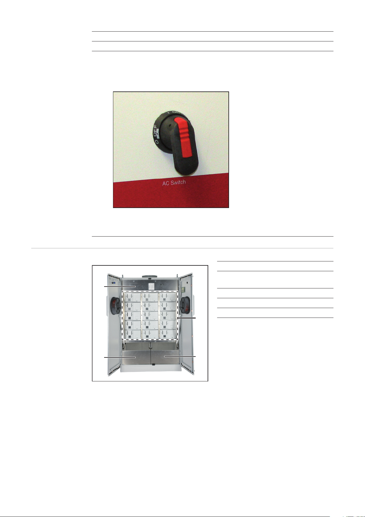
(11) Left fan
(12) AC main switch
The 'AC main switch' is equipped as an AC disconnect for BDEW devices with the
'DE-MS' setup.
Open inverter
product description
(4)
(3)
The AC main switch (AC disconnect) can be locked when turned off.
IMPORTANT The doors cannot be opened when the AC main switch is turned on.
Item Designation
(1) Power stage set racks
(max. 15)
(2) Cover right
(3) Cover left
(4) Cover top
(1)
The connection area is located under the
left and right covers.
(2)
24
Page 27

Cover top:
Item Designation
(5)
(6)
(5) AC main switch back (depending
on country setup)
(6) Shaft for DC main switch
(7) Only for BDEW devices with the
'DE-MS' setup:
Shaft for AC main switch (AC disconnect)
(7) (6)
BDEW device
The grid voltage contactor is located under the top cover on the left (except for BDEW devices with the 'DE-MS' setup).
EN-US
25
Page 28

Connection area product description
Connection area
product description
(4) (5)
Item Designation
(1) Rail with strain relief device clamps for AC and DC wires
(included in the scope of supply for the inverter)
(2) Cable input opening with slide cover
(3) AC connections M10 (L1, L2, L3, N) and ground clamp (PE, solar module frame
ground, etc.)
(4) DC connections M10
(5) Fuse holders for grounding solar modules:
DC+ to PE or DC- to PE
(6) 2 potential-free relays, e.g., for connecting and controlling external ventilation
- with terminals
- with a strain-relief device
(7) Option area
- with standard Fronius Com Card for data communication via Solar Net
- with 2 free slots for option cards
- with a strain-relief device
(6)(3)
(8)
(7)(2)
(9)
(10)(1)
26
The number of free slots and available option cards can vary depending on the
country setup.
(8) 230 V AC sockets,
e.g., for supplying power to DATCOM components, a modem, notebook, etc.
(9) 4-pin power circuit breaker (depending on the country setup)
For interrupting the power supply to the following:
- "Snowball" PC board (fan control)
- Both sockets
- Measurement and monitoring relay
(10) Measurement and monitoring relay (depending on the country setup)
Three-phase monitoring of phase sequence, phase failure, overvoltage, undervoltage and asymmetry, neutral conductor monitoring
Page 29

Terminals in the
area of the potential-free relays
EN-US
(1)
(2)
L N
(3)
Item Description
(1) Jumper slot 'AC COM'
(2) Jumper slot 'external'
(3)
L + N = connection for external AC supply (e.g., for fans, DATCOM, sockets, etc.)
(4)
230 V, connection of phase and neutral conductor
alternating current fuse: 230 V AC / 10 A
IMPORTANT When connecting an external AC power supply, set the jumper at
the 'external' and 'AC COM' jumper slots.
(5)
(6)
S2 + EXT = connection for an external switch for external control of the grid voltage contactor (e.g., to enable the inverter to operate off the grid if required)
(4)
extern
AC COM
S2 EXT NO SC2 NC NC SC1 NO
(5)
(6)
(7)
(8)
(10) (11) (12)
(9)
Switch: normally open contact with min. 230 V / 1 A
IMPORTANT The external switch can only be connected to devices with a grid
voltage contactor.
When connecting an external switch, remove the shorting bar connected in series.
(7) NO = normally open contact for relay contact 2
(8) SC2 = relay contact 2
(9) NC = break contact for relay contact 2
(10) NC = break contact for relay contact 1
(11) SC1 = relay contact 1
(12) NO = normally open contact for relay contact 1
Cable cross-section: 1–16 mm²
Terminal tightening torque: 1.2–1.5 Nm
max. Current per relay output: AC max. 277 V / 10 A, DC max. 24 V / 10 A
The relay contacts can have different functions assigned in the "Basic Service" menu. To
access the "Basic Service" menu, you need to enter the code 22742:
- Press the "Menu" key
- Select the 'Setup' mode
- Press the unassigned "Esc" key five times
- Enter access code 22742
- Select the 'GPSC CFG' parameter
- Set the desired functions for the relay contacts
27
Page 30

Possible functions of relay contacts
Function
number
Activation criterion1) for the switch
contact
Deactivation criterion2) for the
switch contact
1 AC contactor is open AC contactor is
closed
2 Power feed-in possi-
ble on DC side
3 Cabinet fan in opera-
tion
4 Max. interior tem-
perature >/= 40
5 Max. interior tem-
perature >/= 50
Power feed-in not
possible on DC side
Cabinet fan not in
operation
Max. interior temperature </= 30
Max. interior temperature </= 40
6 Triggering of contin-
ual3) and temporary4) service codes
7 Triggering of contin-
Error confirmation
per key press / per
Solar Net command
ual3) service codes
8 Inverter in feed-in
mode
9 The switch-on point
for the effective power limit has been
reached.
Inverter not in feedin mode
The switch-off point
for the effective power limit has been
reached.
Description
Error signal of contactor or no AC grid
Shut-down of external components over
night
(e.g., 50 Hz transformer)
External ventilation /
air conditioning can
be activated
Status display / Relay contact trips
Control of motorized
stop valve
Energy Management
function
5)
1)
Activation = the break contact for the relay contact opens, the normally open contact closes
2)
Deactivation = the break contact for the relay contact closes, the normally open
contact opens
3)
Continual service codes (e.g., inverter malfunction or shutdown, when the service
code is displayed longer than 4 h 15 min.)
4)
Temporary service codes (e.g., brief interruption of feed-in operation, a service
code is triggered more than 50 x per day)
5)
The Energy Management function is automatically activated as soon as one of the
two relay contacts is assigned function number 9,
- either with the values from the factory settings, if the Energy Management
function has never been used,
or
- with the values last set by the user.
28
Page 31

Installation and Startup
Page 32

Page 33

Choosing the Location
EN-US
Choosing the location in general
Criteria for location selection
Due to its IP 20 degree of protection, the inverter is designed exclusively for installation in
closed spaces or containers.
The inverter must be completely covered by a building or structure to protect against rain,
sun, wind-blown dust, fungal infestation, radiation to the cold night sky, etc.
Buildings or structures must fulfill all requirements regarding temperature, humidity and air
filtration. Condensation is not expected.
Only set up on a firm, flat, level and fireproof surface.
Max. ambient temperatures: -20 °C / +50 °C
For use at altitudes above sea level: up to 2000 m
Keep a min. side distance of 350 mm between the inverter and a wall.
The distance between the upper edge of the inverter and the ceiling must be at least 450
mm to prevent trapped air.
The air flow direction within the inverter is from front to top (cold air intake front, hot air
exit top).
When installing the inverter in a closed space, it is necessary to ensure that the hot air
that develops will be discharged by forced ventilation.
Unsuitable locations
Do not install the inverter:
- in proximity to a living area
- in areas where the device is exposed to water
- in areas with large amounts of dust
- in areas with a large amount of conducting dust particles (e.g., iron filings)
- in areas with corrosive gases, acids or salts
- in areas where there is an increased risk of accidents caused by farm animals (horses,
cattle, sheep, pigs, etc.)
- in stables or adjoining areas
- in storage areas for hay, straw, chaff, animal feed, fertilizers, etc.
- in storage or processing areas for fruit, vegetables or winegrowing products
- in areas used in the preparation of grain, green fodder or animal feeds
- in greenhouses
31
Page 34

Transport
Transport The inverter can be transported as follows:
- Using a crane
- On a palette using a forklift or lift truck
- manually
Crane transport
Transport using a
forklift or lift truck
WARNING! Falling devices can be deadly. Use all 4 ring bolts when transporting
the inverter by crane.
WARNING! Falling or toppling devices can be deadly.
- When transporting the inverter by forklift or lift truck secure the inverter from
falling.
- Do not turn, brake, or accelerate in a sudden, jerking manner
Manual transport The inverter can also be transported manually if a crane, forklift or lift truck cannot be used.
NOTE! At least 4 adults are required to manually transport the inverter.
The manufacturer recommends that you remove the power stage sets from the
inverter to reduce its weight for manual transport.
32
Page 35

Removing power stage sets
Opening the Fronius CL
1 2
1
2
3
4
EN-US
2
1
1
1
Removing power
stage sets
WARNING! An electrical shock can be fatal. Danger from grid voltage and DC
voltage from solar modules.
Do not remove power stage sets under load. Before removing power stage sets,
make sure that the AC and DC main switches are turned off in the device interior.
WARNING! An electrical shock can be fatal. Danger from residual voltage from
capacitors.
You must wait until the capacitors have discharged. Discharge takes 5 minutes.
1 1
1
5
4
3
3
2
1
2
1
- Remove the screws at the 4 rails
(4 x 5 screws)
- Remove the 4 rails
- Remove the power stage sets
33
Page 36

Setting up the Fronius CL
Requirements
WARNING! Toppling or falling devices can be deadly. Install the inverter on a lev-
el and stable surface.
A mounting base is required for inverter setup and operation.
The mounting base is available at a height of 100 mm.
The cabling into the inverter can be done from the bottom or side through the mounting
base.
For bottom cabling
- All AC and DC cables to be connected must protrude out of the base at least 400 mm
before inverter setup.
- If possible, data communications cables for connecting option cards should also protrude out of the base.
- The cables must be positioned so that there is at least 1.2 m of free space to the right
of the cables to position the inverter.
Side cabling: Bottom cabling
min. 400 mm
min. 400 mm
Recommendation for max. wire
cross section
Space requirement:
AC + DC
min. 1,2 m
Maximum cross section of AC wires: 70 mm²
Maximum cross section of DC wires: 120 mm²
34
Page 37

Preparing AC and
DC wires
1 1
1
2
EN-US
2
1
400-600 mm
20mm
CA
- Cut the AC and DC wires so that 400
- 600 mm protrudes from the base
- Strip the AC wire so that approx. 20
mm of the insulation remains
1
3
1
2
1
CA
- Strip the AC wires
- Attach the cable lugs
- Strip the DC wires
- Attach the cable lugs
2
DC
35
Page 38

Installing the
mounting base
NOTE! When positioning the mounting base, make sure that the AC and DC
wires on the left are located up to a max. of 100 mm from the inside edge of the
mounting base.
1 2
1
1
2
5
1
6
7
3
2
max. 100 mm
4
2
3
8
4
Different dowels and screws are required for installation of the mounting base depending
on the surface used. Therefore, dowels and screws are not part of the scope of supply for
the inverter. The system installer is responsible for selecting the proper dowels and
screws.
NOTE! To avoid warping of inverter doors, the mounting base should only be attached in a 100% level position.
1
3
6
5
1
3
1
4
2
2
36
Page 39

Preparing the
Fronius CL
CAUTION! An inadequate grounding conductor connection can cause serious in-
juries to persons and damage to (or loss of) property.
The screws on the covers provide an adequate grounding conductor connection
for the housing ground and should not under any circumstances be replaced by
other screws that do not provide a proper grounding conductor connection.
1 1
1
EN-US
2
4
3
5
1
2
Safety
3
4
2
- Open the inverter
- Remove 2 x 2 screws
- Remove 2 covers
WARNING! Toppling or falling devices can be deadly. When sliding the inverter
back on the mounting base, make sure that the inverter does not slip off the
mounting base sideways.
NOTE! When setting the inverter onto the mounting base make sure that the AC
and DC wires are not broken, kinked, crushed or otherwise damaged in any way.
11
7
- Loosen 5 screws
- Open the slide cover as far as possible
37
Page 40

Positioning the
Fronius CL on the
mounting base
using a crane
1
1
1
2
1
2
Manually positioning the Fronius CL on the
mounting base
- Position the inverter over the mounting base using a crane
- Insert AC and DC wires into the cable
input opening on the inverter
1
1
- Lower the inverter onto the mounting
base
- Slide the inverter backwards until it
engages at the stop
1
2
1
2
38
- Position the inverter on the mounting
base so that the back edge of the inverter lies on the front edge of the
mounting base
- Carefully tip the inverter backward
- Insert AC and DC wires into the cable
input opening on the inverter
Page 41

1
3
- Lower the inverter onto the mounting
base
- Slide the inverter backwards until it
engages at the stop
1
2
EN-US
Securing the Fronius CL to the
mounting base
1 1
1
1
2
Tightening torque: 9 Nm - Attach the AC and DC wires on the
side to the strain-relief device
1
3
6
5
- Close the slide cover as far as possible
- Attach 5 screws
2
3
4
Tightening torque: 3 Nm
1
39
Page 42

Information regarding air supply and
connection of an
exhaust pipe
The air supply to the inverter must be at least 1300 m³/h of air (approx. 21 m³/min).
When connecting an exhaust pipe, the counter-pressure created by the pipe must not exceed a maximum value of 150 Pa.
This results in a flow rate of approx. 13 m³/min.
40
Page 43

Connecting the Fronius CL to the public grid (AC)
EN-US
Monitoring the
Grid
AC connections
IMPORTANT! The resistance in the leads to the AC-side connection terminals must be as
low as possible for optimal functioning of grid monitoring.
Legend:
L1 Phase conductor
L2 Phase conductor
L1
L2
L3
N
PE(a)
PE
NOTE! Make sure that the grid neutral conductor is grounded.
L3 Phase conductor
N Neutral conductor
PE Grounding conductor / Ground
PE(a) Grounding conductor / Ground
Connecting aluminum cables
Cross section of
AC wires
Aluminum cables can also be connected to the AC connections.
NOTE! When connecting aluminum cables:
- Follow all national and international guidelines regarding the connection of
aluminum cables
- Follow the instructions of the cable manufacturer
- Use suitable cable lugs: the cable lugs must be suitable for the connection
material (Cu) and the cable material (Al).
The optimal bending radius in the inverter can be achieved using wires with a cross section
of 70 mm². However, AC wires with a larger cable cross section can be connected to the
AC connections of the inverter.
41
Page 44

Safety
WARNING! An electrical shock can be fatal. Danger from grid voltage and DC
voltage from solar modules.
- Never work with live wires! Prior to all connection work, make sure that the
AC and DC wires are not charged.
- Only an authorized electrician is permitted to connect this inverter to the public grid.
- Power stage sets should only be opened by Fronius-trained service personnel.
CAUTION! Danger of damaging the inverter due to an overload of the grid neutral
conductor.
- Do not connect 3-phase devices to one phase
- Never operate multiphase devices in one phase
CAUTION! Danger of damaging the inverter due to improperly connected wires.
Improperly connected wires can cause thermal damage to the inverter and may
cause a fire. When connecting AC and DC wires, make sure that all cables are
secured to the inverter connections using the correct torque.
Connecting the
Fronius CL to the
public grid
NOTE! The phases should be connected in the proper order: L1, L2, L3, N and
PE.
1 2
1
AC
1
OFF
1
3
L1
L2
L3
N
2
M10
42
PE
M10
1
Tightening torque: 30 Nm
Page 45

Maximum ACside overcurrent
protection
Inverter Number of
phases
Fronius CL 36.0 3 36 kW 3 x C 80 A
Fronius CL 48.0 3 48 kW 3 x C 100 A
Fronius CL 60.0 3 60 kW 3 x C 125 A
NOTE! A residual current circuit breaker for the AC connecting cable may be required depending on local regulations, the power supply company as well as other conditions. A type A residual current circuit breaker is generally sufficient in this
case. However, false alarms can be triggered for the residual current circuit
breaker in individual cases and depending on local conditions. For this reason,
Fronius recommends that you use a residual current circuit breaker suitable for a
frequency converter.
NOTE! When using a residual current circuit breaker, the voltage difference between the PE grounding conductor and the N neutral conductor cannot be higher
than 8 V.
Nominal output Fuse protection
EN-US
43
Page 46

Connecting DC wires to the Fronius CL
General Information about Solar
Modules
DC connections
In order to select suitable solar modules and get the most efficient use out of the inverter,
please note the following points:
- If irradiance is constant and the temperature is falling, the open circuit voltage of the
solar modules will increase. Open circuit voltage may not exceed 600 V.
Whenever the open circuit voltage of the solar modules exceeds 600 volts, the inverter
may be damaged, and all warranty rights will become null and void.
- More exact values for dimensioning solar modules for the chosen installation location
can be provided using suitable calculation programs like the Fronius Solar.configurator (available at http.//www.fronius.com).
NOTE! Before connecting solar modules:
- make sure that the voltage specified by the manufacturer corresponds to the
actual measured voltage
- determine whether or not a solar module ground is required
DC+
Connecting aluminum cables
Max. cross section of DC wires
DC-
Aluminum cables can also be connected to the DC connections.
NOTE! When connecting aluminum cables:
- Follow all national and international guidelines regarding the connection of
aluminum cables
- Follow the instructions of the cable manufacturer
- Use suitable cable lugs: the cable lugs must be suitable for the connection
material (Cu) and the cable material (Al).
A max. of 3 DC wires per pole with a max. cross section of 120 mm² can be connected to
the inverter DC connections.
44
Page 47

Safety
WARNING! An electrical shock can be fatal. Danger from grid voltage and DC
voltage from solar modules.
- Never work with live wires! Prior to all connection work, make sure that the
AC and DC wires are not charged.
- Only an authorized electrician is permitted to connect this inverter to the public grid.
- The separate power stage set area should only be disconnected from the
connection area after first being disconnected from the grid power.
- Power stage sets should only be opened by Fronius-trained service personnel.
CAUTION! Danger of damaging the inverter from improperly connected terminals. Improperly connected terminals can cause thermal damage to the inverter
and may cause a fire. When connecting the AC and DC cables, make sure that
all terminals are tightened securely using the proper torque.
EN-US
Connecting DC
wires
1 1
1
M10
1
2
2
Tightening torque: 30 Nm
1
1
M10
2
2
45
Page 48

Connecting several DC wires
You can connect 2 - 3 DC wires per DC connection on the inverter.
A spacer is required to connect 3 wires.
Connecting 2 DC wires: Connecting 3 DC wires:
(2)(1) (3) (4)
(2)(1) (3) (4)
C
B
B
A
A
(7) (6) (5)
(1) Cable B (1) Cable C
(2) Cable lug B (2) Cable lug C
(3) Screw (3) Screw
(4) DC connection on inverter (4) DC connection on inverter
(5) Hex nut (5) Spacer
(6) Cable lug A (6) Cable lug B
(7) Cable A (7) Hex nut
(8) Cable lug A
(9) Cable B
(10) Cable A
(8)(9)(10)
(5)
(6)
(7)
46
Page 49

Fronius CL solar module ground
General Some solar module manufacturers require that the solar modules be grounded.
The inverter allows you to ground solar modules via a fuse or a high ohm resistor in the
connection area either at the negative pole
or the positive pole.
(1) Fuse holder for solar module
ground at the positive pole
(2) Fuse holder for solar module
ground at the negative pole
EN-US
Solar module
ground via fuse
or high ohm resistor
(1)
Solar module ground at negative pole via
fuse or high ohm resistor:
(1)
DC+
(2)
=
DC-
(3)
~
L
L
L
N
PE
(2)
1
2
3
Solar module ground at positive pole via
fuse or high ohm resistor:
(2)(1)
DC+
DC-
=
(3)
~
L
L
L
N
PE
1
2
3
(1) Solar module
(2) Inverter
(3) Fuse / High ohm resistor
Depending on the inverter output, Fronius recommends fuses with the following nominal
current values for the solar module ground:
- Fronius CL 36.0: 2 A
- Fronius CL 48.0: 2 A
- Fronius CL 60.0: 3 A
Fuse dimensions: 10 x 38 mm
IMPORTANT! Fuses for the solar module ground are not included with the inverter. If the
solar module manufacturer requires a ground for solar modules, a suitable fuse must be
ordered separately.
47
Page 50

For solar module grounding using a high ohm resistor, Fronius recommends the "100
kOhm Grounding Kit" option only.
WARNING! An electric shock can be fatal. Danger of an electrical shock due to
incorrect or insufficient solar module grounding.
If the solar module manufacturer requires a solar module ground in the inverter,
this may be provided only via the specified fuse or the high ohm resistor "Grounding Kit 100 kOhm" in order to comply with IEC 62109-2.
Safety
WARNING! An electric shock can be fatal. Danger presented by DC voltage from
solar modules that are exposed to light. When solar modules are grounded, the
inverter's insulation monitoring is deactivated.
- Ensure that grounded solar modules are designed so that they are double insulated according to protection class II.
- Place the relevant safety labels in a clearly visible place on the photovoltaic
system.
- Set the inverter so that a warning message is displayed if the fuse trips.
Safety label for the solar module ground
IMPORTANT! The safety labels and fuse
for the solar module ground are not part of
the scope of delivery for the inverter and
Warnung!
Ein elektrischer Schlag kann tödlich sein.
Gefahr durch DC-Spannung von den
Solarmodulen.
Die Isolationsüberwachung des Wechselrichters ist deaktiviert. Die Solarmodule
sind geerdet.
VorArbeiten an der Photovoltaik-Anlage
AC- und DC-Seite spannungsfrei schalten.
Warnung!
Ein elektrischer Schlag kann tödlich
sein. Gefahr durch DC-Spannung von
den Solarmodulen.
Die Isolationsüberwachung des
Wechselrichters ist deaktiviert. Die
Solarmodule sind geerdet.
VorArbeiten an der Photovoltaik-kAnlageAC- und DC-Seite spannungsfrei schalten.
Warnung!
Ein elektrischer Schlag kann tödlich
sein. Gefahr durch DC-Spannung von
den Solarmodulen.
Die Isolationsüberwachung des
Wechselrichters ist deaktiviert. Die
Solarmodule sind geerdet.
VorArbeiten an der Photovoltaik-kAnlageAC- und DC-Seite spannungsfrei schalten.
Warnung!
Ein elektrischer Schlag kann tödlich sein.
Gefahr durch DC-Spannung von den
Solarmodulen.
Die Isolationsüberwachung des Wechselrichters ist deaktiviert. Die Solarmodule
sind geerdet.
VorArbeiten an der Photovoltaik-Anlage
AC- und DC-Seite spannungsfrei schalten.
Warnung!
Ein elektrischer Schlag kann tödlich
sein. Gefahr durch DC-Spannung von
den Solarmodulen.
Die Isolationsüberwachung des
Wechselrichters ist deaktiviert. Die
Solarmodule sind geerdet.
VorArbeiten an der Photovoltaik-kAnlageAC- und DC-Seite spannungsfrei schalten.
must be obtained separately.
Setting inverters
for grounded solar modules
48
When solar modules are grounded, the inverter's insulation monitoring must be deactivated. For this reason, the inverter must be configured in the second level of the Setup menu
so that an error message is displayed or the inverter turns off when the ground fuse is
blown (depending on the country setup).
The access code 22742 must be entered in order to access the second level of the Setup
menu.
Page 51

Solar module
ground at positive pole: Inserting fuse or "100
kohm Grounding
Kit" option
WARNING! An electrical shock can be fatal. Danger from DC voltage from solar
modules.
The DC main switch is only used to switch off power to the power stage sets.
When the DC main switch is turned off, the solar module ground at the positive
pole remains unaffected. Never touch the DC+ and DC-.
Inserting a fuse:
1
1
*)
1
+
3
EN-US
- Remove the plastic bolts from the fuse
holder (included in the inverter scope
of delivery)
- Insert the fuse into the fuse cover (included in the inverter scope of delivery)
- Insert the fuse with a fuse cover into
the left fuse holder
-
2
- Insert the plastic bolt into the empty
fuse holder
4
+
-
IMPORTANT The right fuse holder for the solar module ground at the negative pole must
have a plastic bolt inserted.
Inserting the fuse at the positive pole grounds the solar module.
Inserting the "100 kohm Grounding Kit" option:
1
1
- Remove the plastic bolts from the fuse
holder (included in the inverter scope
of delivery)
*)
1
- Insert the "100 kohm Grounding Kit"
option into the left fuse holder completely with the plastic jacket
- Insert the plastic bolt into the empty
+
-
2
3
+
-
fuse holder
IMPORTANT The right fuse holder for the solar module ground at the negative pole must
have a plastic bolt inserted.
Inserting the "100 kohm Grounding Kit" option grounds the solar module at the positive
pole via a high ohm resistor.
49
Page 52

Solar module
ground at negative pole: Inserting fuse or "100
kohm Grounding
Kit" option
WARNING! An electrical shock can be fatal. Danger from DC voltage from solar
modules.
The DC main switch is only used to switch off power to the power stage sets.
When the DC main switch is turned off, the solar module ground at the negative
pole remains unaffected. Never touch the DC+ and DC-.
Inserting a fuse:
1
1
*)
1
+
4
- Remove the plastic bolts from the fuse
holder (included in the inverter scope
of delivery)
- Insert the fuse into the fuse cover (included in the inverter scope of delivery)
- Insert the fuse with a fuse cover into
the right fuse holder
-
2
- Insert the plastic bolt into the empty
fuse holder
3
+
-
IMPORTANT The left fuse holder for the solar module ground at the positive pole must
have a plastic bolt inserted.
Inserting the fuse at the negative pole grounds the solar module.
Inserting the "100 kohm Grounding Kit" option:
1
1
- Remove the plastic bolts from the fuse
holder (included in the inverter scope
of delivery)
*)
1
- Insert the "100 kohm Grounding Kit"
option into the right fuse holder completely with the plastic jacket
- Insert the plastic bolt into the empty
+
-
3
2
+
-
fuse holder
50
IMPORTANT The left fuse holder for the solar module ground at the positive pole must
have a plastic bolt inserted.
Inserting the "100 kohm Grounding Kit" option grounds the solar module at the negative
pole via a high ohm resistor.
Page 53

Inserting power stage sets
Overview A sticker is located in the inverter on the top cover. The sticker provides an overview of the
steps required for inserting power stage sets. A detailed description of the sticker can be
found in 'Troubleshooting and maintenance' in the 'Replacing power stage sets' section.
EN-US
4
4
4
4
4
1101
PS 13
1010
PS 10
0111
PS 07
0100
PS 04
0001
PS 01
2
ON
3
4
1
2
ON
3
4
1
2
ON
1
ON
1
ON
1
ON
1
ON
1
1110
PS 14
3
4
2
1011
PS 11
3
4
2
1000
PS 08
3
4
2
0101
PS 05
3
4
2
0010
PS 02
3
4
2
1
ON
ON
ON
ON
ON
1100
PS 12
3
4
1
2
1001
PS 09
3
4
1
2
0110
PS 06
3
4
1
2
0011
PS 03
3
4
1
2
0000
PS 00
3
4
1
2
ON
3
1
2
ON
3
1
2
ON
3
1
2
ON
3
1
2
ON
3
1
2
General One slot in the inverter is assigned to each power stage set rack. In order to avoid mixing
up the slots, positioning bolts are used on the back of the power stage set racks and a corresponding recess is available for the slot.
Positioning bolt on the back of the power
Opening for the slot
stage set:
51
Page 54

Slot arrangement
Dip switches for
identifying power
stage set racks
PS 13PS 12
PS 14
PS 11PS 10PS 09
PS 08PS 07PS 06
PS 05PS 04PS 03
PS 01PS 00
PS 02
A dip switch on the front of the power stage set is used to identify each individual power
stage set in the inverter. The dip switch must be set exactly for each individual slot.
Dip switches on the front of the power stage set:
4
ON
3
2
1
52
Page 55

Dip switch settings for each slot
ON
1
2
ON
1
2
ON
1
2
ON
1
2
ON
1
2
110 0
PS 12
3
4
1001
PS 09
3
4
0110
PS 06
3
4
0011
PS 03
3
4
0000
PS 00
3
4
ON
1
2
ON
1
2
ON
1
2
ON
1
2
ON
1
2
1101
PS 13
3
4
1010
PS 10
3
4
0111
PS 07
3
4
0100
PS 04
3
4
0001
PS 01
3
4
ON
1
2
ON
1
2
ON
1
2
ON
1
2
ON
1
2
1110
PS 14
3
4
EN-US
1011
PS 11
3
4
1000
PS 08
3
4
0101
PS 05
3
4
0010
PS 02
3
4
Inserting power
stage sets
NOTE! Check the following before inserting power stage sets into the inverter:
- The location of the positioning bolt
- Whether or not the dip switch is set for the slot
IMPORTANT When inserting power stage sets, the plastic front of the power stage set
must be inserted flat against the side metal supports.
If a power stage set cannot be inserted completely into the inverter, then the power stage
set has been inserted into the wrong slot.
1 1
1
1
2
8
2
1
3
3
3
3
3
3
1
Tightening torque: 3.5 Nm
- Insert 4 rails
- Secure rails using 4 x 5 screws
53
Page 56

Closing the Fronius CL
Closing the Fronius CL
CAUTION! An inadequate grounding conductor connection can cause serious in-
juries to persons and damage to (or loss of) property.
The screws on the covers provide an adequate grounding conductor connection
for the housing ground and should not under any circumstances be replaced by
other screws that do not provide a proper grounding conductor connection.
1 1
1
2
3
4
5
1
1
2
1
Tightening torque: 2.5 Nm - Close doors
- Replace covers
- Secure with screws
1
1
1
3
- Close door latches
2
1
4
3
54
Page 57

Inserting Option Cards
EN-US
Safety
Opening the Fronius CL
WARNING! An electrical shock can be fatal. Danger from grid voltage and DC
voltage from solar modules.
- Never work with live wires! Prior to all connection and maintenance work,
make sure that the AC and DC wires are not charged.
- The connection area should only be opened by a licensed electrician.
- Power stage sets should only be opened by Fronius-trained service personnel.
WARNING! An electric shock can be fatal. Danger from residual voltage from capacitors.
You must wait until the capacitors have discharged. Discharge takes 5 minutes.
NOTE! Follow general ESD precautions when handling option cards.
When adding option cards to the inverter, please follow all inverter safety instructions and
information before opening the inverter.
1 2
1
2
1
2
OFF
1
0
2
3
4
CAUTION! An inadequate grounding conductor connection can cause serious injuries to persons and damage to (or loss of) property.
The screws on the covers provide an adequate grounding conductor connection
for the housing ground and should not under any circumstances be replaced by
other screws that do not provide a proper grounding conductor connection.
55
Page 58

1 2
3
1
1
4
1
2
3
4
5
5
Inserting option
cards
1
1
1
2
- Insert option cards into free slots and
secure.
56
Page 59

Connecting option cards, laying
data communication wires
CAUTION! Danger of short circuit by loose metal parts from knockouts. Loose
metal parts in the inverter may cause short circuits when the inverter is powered
up. When removing knockouts, make sure that
- no loose metal parts fall into the inverter
- any metal pieces that do fall into the inverter are removed immediately
EN-US
1
1
3
2
1
54
5
- Remove the knockouts
- Remove strain-relief device
Only when data communication cables are not run out the base like the AC and DC wires,
but rather run into the inverter from the side:
1
2
- Remove right side panel of the
mounting base
- Drill a hole for inserting the data com-
3
1
munication cable on the side panel of
the mounting base. Attach a metric
screw joint if required.
3
2
4
NOTE! To prevent damage to the data communication cables from the rough
edges of wire input openings, install a suitable edge guard in the knockout and
drilling on the side of the mounting base (e.g., a rubber bushing).
57
Page 60

1
3
- Run data communication cable
through the open side of the mounting base and through the knockout
into the inverter
- Connect the data communication cable to the option card
3
2
1
1
4
1
2
3
3
4
1
6
1
5
1
- Secure data communication cable
with strain-relief device and screws
- Attach side panel to mounting base
58
1
Tightening torque: 2 Nm
3
3
2
Page 61

Closing the Fronius CL
CAUTION! An inadequate grounding conductor connection can cause serious in-
juries to persons and damage to (or loss of) property.
The screws on the covers provide an adequate grounding conductor connection
for the housing ground and should not under any circumstances be replaced by
other screws that do not provide a proper grounding conductor connection.
1 1
1
EN-US
2
2
3
4
5
1
1
1
Tightening torque: 2.5 Nm - Close doors
- Replace covers
- Secure with screws
1
3
2
1
1
1
- Close door latches
4
3
59
Page 62

Commissioning
Factory Configuration
Start-up operation
The inverter has been pre-configured in the factory and is ready for operation.
To change your inverter settings, please see "The Setup Menu" section in these instructions.
After connecting the inverter to the solar modules (DC) and public grid (AC):
- Attach all covers
- Close and lock doors
- Flip AC main switch to position - 1 -
- Flip DC main switch to "ON" position
1 2
1
2
1
4
3
2
ON
1
1
2
Setting Inverters
for Available Solar Module
Ground
- As soon as the solar modules produce sufficient power, the Operating Status LED
lights up orange. The screen displays the startup phase. The orange LED indicates
that the feed-in mode of the inverter will begin shortly.
- After the automatic inverter start, the Operating Status LED lights up green.
- Provided that power continues to feed into the grid, the Operating Status LED will remain green to confirm that the inverter is functioning correctly.
NOTE! If a solar module ground is used, the corresponding grounding mode must
be set in the 'Basic Service Menu' after the inverter is turned on.
A 5-character access code is required to access the 'Basic Service Menu.' This
access code will be provided by Fronius upon request.
If a solar module ground is being used, the status message 502 "Insulation value too low"
will be displayed after the inverter is turned on and upon completion of the startup phase.
Confirm the status message by pres-
1
sing the "Enter" key
60
Page 63

The current insulation value is displayed.
Press the "Menu" key
2
The "menu" is displayed.
Select the "Setup" mode using the
3
"Left" or "Right" keys
Press the unassigned "Esc" key 5 x
4
"CODE" is displayed, the first digit flashes.
Use the "Up" and "Down" keys to
5
select the value for the first digit of the
access code
EN-US
Press the "Enter" key
6
The second digit flashes.
Use the "Up" and "Down" keys to
7
select a value for the second digit of
the access code
Press the "Enter" key
8
The third digit flashes.
Use the "Up" and "Down" keys to
9
select a value for the third digit of the
access code
Press the "Enter" key
10
The fourth digit flashes.
Use the "Up" and "Down" keys to
11
select a value for the fourth digit of the
access code
Press the "Enter" key
12
61
Page 64

The fifth digit flashes.
Use the "Up" and "Down" keys to
13
select a value for the fifth digit of the
access code
Press the "Enter" key
14
The access code flashes.
*) ... Code example
*)
Press the "Enter" key
15
The inverter is now in the Basic Service
menu, the first parameter is displayed:
- 'MIXMODE' for multiphase inverters
- 'DCMODE' for one-phase inverters
Use the "Up" or "Down" keys to select
16
the 'GNDMODE' parameter
Press the "Enter" key
17
The grounding mode is displayed.
Use the "Up" and "Down" keys to
18
select the grounding mode:
62
OFF = no solar module ground (factory setting)
NEG = solar module ground at negative
pole
Page 65

POS = solar module ground at positive pole
-100 kohm = solar module ground at negative pole using high ohm resistor
+100 kohm = Solar module ground at positive pole using high ohm resistor
Press the "Enter" key to apply the re-
19
quired grounding mode
Press the "Esc" key to exit the Basic
20
Service menu
EN-US
63
Page 66

64
Page 67

Operation
Page 68

Page 69

Keys and symbols
Controls and Indicators
EN-US
(1)
(6)
Item Function
(1) Display
for displaying values, settings and menus
(2) Operating Status LED
for displaying the operating status
(3) "Enter" key
for confirming a selection
(4) "Menu / Esc" key
for scrolling through menu options
for exiting the Setup menu
(5)
(2)
(4) (3)
(5) "Down/Right" key
depending on the selection:
for navigating down
for navigating right
(6) "Left/Up" key
depending on the selection:
for navigating left
for navigating up
67
Page 70

Display The display unit's power is supplied via the safety-low voltage of the solar modules, which
means that the display unit can be used only in the daytime.
IMPORTANT! The inverter display is not a calibrated measuring instrument. A slight inaccuracy of a few percent is intrinsic to the system. A calibrated meter will be needed to make
calculations for the power supply company.
(1) (2)
(13)
(12)
(11) (10)
Item Function
(1) Icons for the "Now" display mode
(2) Icons for the "Day" display mode
(3) Icons for the "Year" display mode
(4) Icons for the "Total" display mode
(5) Icons for the "Setup" display mode
(6) Icons for operating conditions
(3) (4) (5)
(6)
(7)
(9) (8)
The value shown represents the maximum value within the period of
observation (depending on which display mode is selected).
The value shown represents the minimum value within the period of
observation (depending on which display mode is selected).
Important The minimum and maximum values displayed do not represent the absolute extreme values, because data are recorded only
at two-second intervals.
... appears when values are displayed which are directly associated
with the solar modules
... appears when values are displayed which are directly associated
with the public grid
... appears with data readings that are directly related to the inverter
(7) Range for display unit
for displaying the applicable measuring unit
(8) Icon for the "Enter" key
68
Page 71

Item Function
(9) Icons for the "Menu/Esc" key
(10) Icons for the "Down/Right" key
(11) Icons for the "Left/Up" key
(12) Range for display value
for displaying the value
(13) Output bar (not active during setup)
indicates the output power fed into the grid at a given moment - regardless of the
display mode chosen. The screen displays % of the maximum possible output
power of your solar inverter
EN-US
Operating Status
LED
Position of Operating Status LED on the Inverter
Depending on the operating status, the
Operating Status LED assumes different
colors:
Operating Status LED Explanation
Steady green A green light starts as soon as the inverter has completed the
startup phase, and stays green as long as the operation of feeding power into the grid continues.
It indicates problem-free operation of the photovoltaic system.
flashes green The photovoltaic system is working correctly, a status code is on
the display.
When a status code is shown, rectify the relevant condition by
going to the "Maintenance and service" chapter, "Status diagnosis and troubleshooting" section. The status code can be acknowledged by pressing the "Enter" key.
lights up orange The inverter enters an automatic startup phase as soon as the
solar modules are delivering sufficient power after sunrise.
Flashes orange A warning is shown on the display
or
the inverter has been set to standby operation in the Setup
menu (= manual shutoff of operation).
The next day, operation will resume automatically.
During the time the LED flashes orange, operation can be resumed manually at any time (see section "The Setup menu")
69
Page 72

Operating Status LED Explanation
lights up red General status: the respective status code is shown on the
screen
remains dark There is no connection to the solar modules,
no solar module power due to darkness.
A list of most status codes, the corresponding status information, their status causes and
repair measures can be found in the chapter "Troubleshooting and Maintenance," section
"Status Diagnosis and Troubleshooting."
70
Page 73

Startup Phase and Grid Feed-in Mode
Startup phase The inverter carries out a self test after being turned on automatically. Then a test of the
public grid is carried out. This test can take from several seconds up to several minutes
depending on local regulations. During the startup sequence the illumination of the Operating Status LED is orange.
Test Procedure 1. Segment test
All display elements light up for about one second
2. Self test of important inverter components
- The inverter goes through a master check list for several seconds
- The display will show "TEST" as well as the component currently being tested
(e.g., "LED")
EN-US
3. Synchronization with grid:
- "WAIT PS" is displayed, the inverter icon flashes: The inverter waits for all power
stage sets on the grid to be operational. This procedure is dependent on the DC
voltage.
- Next, the display shows "SYNC AC," the grid icon flashes
4. Startup test
- Before the inverter begins feeding power into the grid, grid conditions are tested
according to local regulations.
- The display shows "START UP"
The startup test can take anything from just a few seconds up to several minutes de-
71
Page 74

pending on national regulations. The time elapsed is indicated by a bar shrinking from
the top down.
Whenever two scale divisions stop flashing and disappear, 1/10 of the total duration
of the test is over.
Operation of
Feeding Energy
into the Grid
- Once the tests have been completed, the inverter starts feeding power into the grid.
- The display shows the present power feeding into the grid.
- The Operating Status LED lights up green, and the inverter starts operating.
72
Page 75

Navigation in the Menu Level
EN-US
Activating display
illumination
Automatic switch
to the "Now" display mode or the
startup phase
Accessing the
Menu Level
Press any key
1
The display illumination is activated.
If no key is pressed for 30 seconds, the display backlight goes out (provided that the
display illumination is set to automatic in the Setup menu).
The Setup menu also offers a choice between a permanently lit or permanently dark
display.
If no key is pressed for 2 minutes:
- While power is being fed into the grid, the inverter automatically switches to the "Now"
display mode and the present output power is displayed.
- If the inverter is not feeding power into the grid, the inverter automatically switches to
the startup phase for synchronization with the grid.
The inverter switches to the "Now" display mode or startup phase from anywhere within the display modes or the Setup menu.
Press the "Menu" key (1)
1
(1)
"Menu" will appear on the display
The inverter is now in the menu level.
From the menu level you can
- set the desired display mode
- access the Setup menu
73
Page 76

The Display Modes
The Display
Modes
Selecting a Display Mode
"Now" display mode ...... Displays real-time values
"Day" display mode ...... Displays values for power fed into the grid during that day
"Year" display mode ...... Displays values for the present calendar year - only avail-
able in combination with optional Fronius Datalogger
"Total" display mode ...... Displays values for power fed into the grid since the in-
verter was started for the first time
Accessing the menu level
1
Use the "left" (7) or "right" (6) keys to
(1) (2) (3) (4)
2
select your preferred display mode (1)
- (4)
Press "Enter" (5)
3
(7)
(6) (5)
The selected display mode is shown, e.g.,
"Day" display mode.
IMPORTANT! The "Year" menu option is
supported only when the optional Fronius
Datalogger is connected. This system upgrade includes a real-time clock.
74
Page 77

Overview of display values
Display
mode
"Now" W - Output power
"Day" kWh / MWh - Output energy
Icon Unit Optional Display value
V - AC grid voltage
A - Output current
Hz - Grid frequency
V - Solar module voltage
A - Module current
megaohms - Insulation resistance
HH:MM x Time
°C / °F - Supply air temperature
rpm - Speed of left fan
rpm - Speed of right fan
EN-US
"Year" Currency - Yield
"Total" kg / T - CO2 reduction
W - Maximum output power
V - Maximum grid voltage
V - Minimum grid voltage
V - Maximum solar module voltage
HH:MM - Operating hours of the inverter
x Optional
If the DatCom component for the required options are not available, the message
"N.A." (not available) is shown.
75
Page 78

Display Values in "Now" Display Mode
Selecting the
"Now" Display
Mode
Display values in
the "Now" display
mode
(1) (2)
Select the "Now" display mode
1
The first display value in the "Now" display
mode appears
Use the "Down" (2) key to scroll to the
2
next display value
Scroll back using the "Up" key (1)
Output power
power (in watts) currently being fed into
the grid
The "Enter" key is active for BDEW devices with the "DE-MS" setup.
- The apparent power can be displayed by pressing the "Enter" key.
- The present operating mode can be displayed by pressing the "Up" and "Down"
keys.
The "Enter" key can also be active if a Fronius Power Control Box is located in Solar Net
and power reduction has been triggered by the utility company.
- The power reduction is displayed as a % by pressing the "Enter" key.
- You can display how long the power reduction has been in effect by pressing the
"Up" and "Down" keys.
In cases where both are occurring, you can display the apparent power by pressing the
"Enter" key. Then you can scroll through the remaining parameters using the "Up" and
"Down" keys.
- You can return to the menu level by pressing the "Menu" key.
Grid voltage
External conductor voltage (volts)
- The phase voltage can be displayed
by pressing the "Enter" key.
- The phase voltage of the other
For example, phase voltage for phase L1:
phases can be displayed by pressing
the "Up" and "Down" keys.
- You can return to the menu level by
pressing the "Menu" key.
76
Page 79

For example, phase current for phase L3:
Output current
current supplied to the grid at the particular moment (amperes)
EN-US
- The phase current can be displayed
by pressing the "Enter" key.
- The phase current of the other
phases can be displayed by pressing
the "Up" and "Down" keys.
- You can return to the menu level by
pressing the "Menu" key.
Grid frequency
(hertz)
Solar module voltage
voltage of the solar modules at the moment of data display (volts)
Solar module current
current supplied by solar modules at the
moment of data display (amperes)
Insulation resistance of photovoltaic
system
(megaohms)
for ungrounded solar modules
WARNING! An electric shock can be fatal. The positive and negative poles of the
photovoltaic system should never be touched with an insulation resistance of <
600 kohm. An insulation resistance of < 600 kohm may be due to an inadequately
insulated DC lead or defective solar modules. In the event that the insulation resistance is too low, you must contact your Fronius service partner.
The insulation resistance is the resistance between the positive or negative pole of the
photovoltaic system and the ground potential. If an insulation resistance > 600 kilohms is
shown, this means that the photovoltaic system is adequately insulated.
An insulation resistance of less than 600 kilohms indicates an error.
When the insulation resistance is less than 10 megaohms, the display differentiates between:
- negative potential of the ground (polarity sign '-')
- positive potential of the ground (polarity sign '+')
77
Page 80

Display example of a negative potential
(polarity sign "-")
Short circuit between DC- lead and
ground
Display example of a positive potential
(polarity sign '+')
Short circuit between DC+ lead and
ground
Time (optional datalogger)
When the time on the inverter or a system
upgrade is changed, this changes the time
on all devices connected via Solar Net.
Supply air temperature
Temperature of the supply air used to cool
the inverter
(° C)
The area for unit display switches between ‘°C’ and ‘AMB.’
Speed of left fan - FAN 1
(rpm)
The area for unit display switches between ‘RPM’ and ‘FAN1.’
Speed of right fan - FAN 2
(rpm)
The area for unit display switches between ‘RPM’ and ‘FAN2.’
Options If the DatCom component for the required options is not available, the message "N.A." (not
available) is shown.
78
Page 81

Display Values in "Day / Year / Total" Display Modes
General For the inverter, the day begins when it switches on. If the DC supply line is disconnected,
the following parameters within the "Day" display mode will be reset after repeating the
startup:
- Return (currency can be selected)
-CO2 reduction (kg)
- Maximum output power (watts)
- Maximum grid voltage (volts)
- Minimum grid voltage (volts)
- Service hours completed by the inverter
If an optional Fronius Datalogger is available, the display values listed always apply to the
whole day.
EN-US
Selecting "Day /
Year / Total" Display Mode
First Display Value in the "Day" Display
Mode:
(1) (2) (1) (2)
First Display Value in the "Total" Display
Mode:
First Display Value in the "Year" Display
Mode:
(1) (2)
Select the "Day" or
1
"Year" or
"Total" display mode
The first display value in the selected display mode appears.
Use the "Down" (2) key to scroll to the
2
next display value
Scroll back using the "Up" key (1)
79
Page 82

Display values in
the 'Day / Year /
Total' display
modes
Output energy
Energy fed into the grid over the period of
time in question (kWh / MWh)
Due to the variety of different monitoring systems, there can be deviations between the
readings of other metering instruments and the readings from the inverter. For determining the energy supplied to the grid, only the readings of the calibrated meter supplied by
the electric utility company are relevant.
Yield
Amount of money earned during the period of time in question (currency can be selected in the Setup menu)
As was the case for the output energy, readings may differ from those of other instruments.
'The Setup menu' section describes how to set the currency and rate for the output energy. The factory setting depends on the respective country-specific setting.
CO2 reduction
CO2 emissions saved during the monitored period
(kg / T; T = tons)
The area for unit display switches between ‘kg’ or ‘T’ and ‘CO2.’
The CO2 meter gives an indication of CO2 emissions that would be released during the
generation of the same amount of electricity in a combustion power plant.
The factory setting is 0.59 kg / kWh (source: DGS - the German Society for Solar Energy).
Maximum output power
Highest output power of the inverter
during observation period (watts)
80
Page 83

For example, maximum phase voltage for
phase L1:
Maximum grid voltage
Highest reading of grid voltage (V) during
observation period
EN-US
The 'Enter' key is active in the 'Total' display mode depending on the country setup or the device-specific settings.
- The maximum phase voltage measured during the time in question can
be displayed by pressing the 'Enter'
key.
- The maximum phase voltage of the
other phases measured during the
time in question can be displayed by
pressing the 'Up' and 'Down' keys.
- You can return to the menu level by
pressing the 'Menu' key.
Minimum grid voltage
Lowest reading of grid voltage (V) during
observation period
Maximum solar module voltage
Highest reading of solar module voltage
(V) during observation period
Operating hours
Indicates how long the inverter has been
operating
(HH:MM)
Duration of operation is shown in hours and minutes up to 999 h and 59 min (display:
‘999:59’). After that only full hours are displayed.
Although the inverter does not operate during the night, all sensor data are recorded
around the clock.
Options If the DatCom component for the required options is not available, the message "N.A." (not
available) is shown.
81
Page 84

The Setup Menu
Presetting The inverter is pre-configured and ready to use. No manual control is necessary for feeding
the power it generates into the grid.
The setup menu allows easy readjustment of the inverter's preset parameters to your
needs.
Accessing the
Setup Menu
(1)
(4) (3) (2)
Switch to the menu level (press the
1
"Menu" key)
Select the "Setup" (1) mode using the
2
"Left" (4) or "Right" (3) keys
Press "Enter" (2)
3
The Setup Menu’s first menu item "STANDBY" is shown.
82
Page 85

Scrolling through
Menu Items
Example: "STANDBY" menu item Example: "CONTRAST" menu item
(1) (2) (1) (2)
Access the Setup menu
1
Scroll through the available menu items using the "Up" (1) and "Down" (2) keys
2
EN-US
83
Page 86

Menu Items in the Setup Menu
STANDBY
Manual activation / deactivation of Standby
operation using the "Enter" key
Unit -
Setting range Enter
Factory setting Automatic operation of feeding energy into the grid (Standby
deactivated)
- The power electronics are switched off in standby mode. No power is fed into the grid.
- The Operating Status LED flashes orange.
- The orange flashing Operating Status LED stops at dusk.
- After the subsequent sunrise, the power supply operation into the grid is resumed automatically (after completion of the startup phase the LED is illuminated green).
- Grid supply operation can be resumed at any time whenever the LED is flashing orange (deactivate "STANDBY").
If the Standby mode is activated by pressing the "Enter" key, the display alternates between "STANDBY" and "Enter:"
CONTRAST
To maintain Standby operation:
- Press the "Esc" key
To end Standby operation:
- Press the "Enter" key
Contrast setting on LCD display
Unit -
Setting range 0 - 7
Factory setting 7
Since contrast depends on temperature, it may be necessary to adjust the "CONTRAST"
menu item when ambient conditions change.
84
Page 87

LIGHT MODE
Initial setting for display illumination.
EN-US
Unit -
Setting range AUTO / ON / OFF
Factory setting AUTO
AUTO: The display illumination will stop 30 seconds after the last time
a key has been pressed.
ON: The display will remain illuminated whenever power is supplied
to the grid.
OFF: The display illumination will be permanently off.
IMPORTANT! The "LIGHT MODE" setting only relates to the display's background illumination. The LCD display will still remain on during operation. Its energy consumption is less
than one mW (1/1000 W).
CASH
CO2
Sets the currency and charge rate for the
output energy to the grid
Unit -
Display area Currency / Charge rate / kWh
Factory setting (depends on the country setting)
Setting of CO2 reduction factor
Unit kg/kWh, T/kWh
Setting range 00,01 - 99,99
Factory setting 0.59 kg/kWh
85
Page 88

YIELD
Setting
- an OFFSET value for the total energy
display
- a measurement correction value for
the Day, Year and Total energy display
Setting range OFF SET / CALI.
OFF SET
Offset is an amount of energy (in Wh, kWh, or MWh) that can be added to the lifetime total
energy output of the inverter to give it a ‘head start.’
Unit Wh / kWh / MWh
Setting range 5-digit + k... / M...
1 kWh = 1000 Wh
1 MWh = 1000000 Wh
Factory setting 0
CALI.
Preset correction value, so that the data shown on the inverter display corresponds to the
calibrated data shown on the electric meter
IG no.
Unit %
Setting range -5.0 - +5.0 in increments of 0.1
Factory setting 0
Number setting (address) of the inverter in
a setup comprising multiple solar inverters
linked together
Unit -
Setting range 01 - 99 (100th inverter = 00)
Factory setting 1
IMPORTANT! Each inverter must be assigned its own address when connecting several
inverters in a data communications system.
86
Page 89

DAT COM
Indicates status of data transmission, function test or activates and resets various option (e.g., Fronius Signal Card, Fronius
Personal Display Card, Fronius Interface
Card, Fronius TAC Card, etc.)
Setting range Displays OK COM or ERROR COM;
SIGCD TEST / PDCD RST / IFCD RST / TAC TEST
OK COM / ERROR COM
Displays data communication available via Solar Net or an error that occurred in data communication
Examples of options:
EN-US
TIME
SIGCD TEST
Function test for the Fronius Signal Card option
*)
PDCD RST
Resets the Fronius Personal Display Card option
IFCD RST
Resets the Fronius Interface Card option
TAC TEST
Function test for the Fronius Power Relay Card (TAC) option
*)
*) The Fronius Signal Card and Fronius Power Relay Card (TAC) options are not
available for the Fronius CL.
These functions were implemented without additional option cards on the "Snowball" PC board (fan controller) via the potential-free relays.
Date and time setting
Unit DDMMYYYY, HH:MM
Setting range Date / Time
Factory setting -
IMPORTANT! The "TIME" menu item is only supported when the Fronius Datalogger option is installed.
87
Page 90

LIMIT CFG
Used to display settings relevant to a power
supply company. The displayed values depend on the respective country setup or device-specific inverter settings.
Display range U IL Max / U IL/TRIP* Max / U IL Min / U IL/TRIP* Min / U OL
Max / U OL/TRIP* Max / U OL Min / U OL/TRIP* Min / U RC Max
/ U RC Min / U LL
FREQ IL Max / FREQ IL/TRIP* Max / FREQ IL Min / FREQ IL/
TRIP* Min / FREQ OL Max / FREQ OL/TRIP* Max / FREQ OL
Min / FREQ OL/TRIP* Min / FREQ RE Max / FREQ RE Min
START TIME/INIT* / START TIME/RCON*
AGF / EMI COMP / POWER LIM / MIX MODE
* Alternating display, e.g.:
IL "Inner Limit"
OL "Outer Limit"
Different clearing times can be assigned to the inner limit IL and the outer limit OL depending on the country setup or device-specific settings.
E.g.:
- Short clearing time for a deviation from the outer limit
- Longer clearing time for a deviation from the inner limit
U IL Max
Upper inner grid voltage limit in V
U IL/TRIP Max
Clearing time for exceeding the upper inner grid voltage limit in P**
U IL Min
Lower inner grid voltage limit in V
U IL/TRIP Min
Clearing time for falling below the lower inner grid voltage limit in P**
U OL Max
Upper outer grid voltage limit in V
U OL/TRIP Max
Clearing time for exceeding the upper outer grid voltage limit in P**
88
U OL Min
Lower outer grid voltage limit in V
U OL/TRIP Min
Clearing time for falling below the lower outer grid voltage limit in P**
Page 91

U RC Max
"Reconnection"
Upper voltage limit for reconnection to the public grid after disconnection due to an unacceptable parameter deviation
U RC Min
"Reconnection"
Lower voltage limit for reconnection to the public grid after disconnection due to an unacceptable parameter deviation
U LL
"Longtime Limit"
Voltage limit in V for the voltage average determined over a longer time period
FREQ IL Max
Upper inner grid frequency limit in Hz
FREQ IL/TRIP Max
Clearing time for exceeding the upper inner grid frequency limit in P**
FREQ IL Min
Lower inner grid frequency limit in Hz
FREQ IL/TRIP Min
Clearing time for falling below the lower inner grid frequency limit in P**
EN-US
FREQ OL Max
Upper outer grid frequency limit in Hz
FREQ OL/TRIP Max
Clearing time for exceeding the upper outer grid frequency limit in P**
FREQ OL Min
Lower outer grid frequency limit in Hz
FREQ OL/TRIP Min
Clearing time for falling below the lower outer grid frequency limit in P**
** P = grid periods; 1 P corresponds to 20 ms at 50 Hz and 16.66 ms at 60 Hz
FREQ RC Max
"Reconnection"
Upper grid frequency limit for reconnection to the public grid after disconnection due to an
unacceptable parameter deviation
FREQ RC Min
"Reconnection"
Lower grid frequency limit for reconnection to the public grid after disconnection due to an
unacceptable parameter deviation
START TIME/INIT
Startup time of the inverter in s
START TIME/RCON
Reconnection time in s after a grid error
89
Page 92

AGF
"Advanced Grid Features"
Display range Q MODE / GPIS / GFPR / FULL/LVRT
Q MODE Mode for reactive power specification
- CONST / COSP***
Constant cos phi specification
- CONST / Q REL***
Constant specification of the relative reactive power in %
- CONST / Q ABS***
Constant specification of an absolute reactive power in var
- COSP (P)
cos phi specification depending on the effective power
- Q (U)
Relative reactive power specification regarding the current
grid voltage
- Q (P)
Relative reactive power specification depending on the effective power
- OFF
The inverter is operating in the pure effective power range
(cos phi = 1)
GPIS "Gradual Power Increment at Startup"
SoftStart function regarding how fast the inverter should increase the power
ON / OFF / N.A.
GFPR "Grid Frequency Depending Power Reduction"
Power reduction depending on the grid frequency
ON / OFF / N.A.
FULL / LVRT*** "Low Voltage Ride Through"
Function for bridging a grid voltage gap that was caused by grid
voltage parameters outside of the limits
ON / OFF / N.A.
EMI COMP
Compensation of the EMC filter during operation
ON / OFF / N.A.
POWER LIM
Constant apparent power limiting
MIX MODE
DC operating type
*** alternating display
N.A. not available
90
- Press the "Enter" key to display the respective value
- Press "Esc" to exit the displayed value
Page 93

STATE FAN
Fan status indicator
EN-US
Display area N.I. FAN / SAFETY X and STOP X / SELF and TEST / O.K. FAN
N.I. FAN No communication between the inverter control unit (IG Brain)
and the fan controller (Snowball)
STATE PS
SAFETY X and
STOP X
SELF and TEST Running a self test
O.K. FAN Fans are OK and operating normally
When there is a communication connection and no self test has been run, you can trigger
the fan controller self test by pressing the "Enter" key.
- "TEST" is displayed after pressing the "Enter" key.
- Repressing ‘Enter’ triggers the fan controller self test. The display then switches back
to the ‘STATE FAN’ menu item.
Fans are stopped for safety reasons;
'x' describes the error:
0 ... general error (over-temperature, overcurrent)
1 ... left fan malfunction
2 ... right fan malfunction
3 ... left and right fan malfunction
4 ... fan in connection area malfunction
5 ... left fan and fan in connection area malfunction
6 ... right fan and fan in connection area malfunction
7 ... all 3 fans malfunction
Status display of power stage sets; the last
error that has occurred can be displayed
IMPORTANT! Due to the low level of irradiance early in the morning and in the evening,
the status codes 306 (power low) and 307 (DC low) are displayed routinely at these times
of day. These status messages do not indicate any kind of fault.
91
Page 94

VERSION
Displays the version number and serial
number of the electronic components (e.g.,
IG Brain, power stage sets, display, country
setup)
Unit -
Display area MAIN CTRL / LCD / PS (PS00, PS01 ... PS14) / SNOW BALL
Factory setting -
MAINCTRL Version information of the IG Brain unit (inverter controller)
LCD Version information of the display
PS Version information of the power stage sets (PS00 - PS14)
SNOW BALL Version information of the Snowball PC board (controls the fan
among other things)
92
Page 95

Setting and Displaying Menu Items
EN-US
Setting Menu
Items - General
Access the Setup menu
1
Use the "Up" or "Down" keys to select the desired menu item
2
Press the "Enter" key
3
The first digit of a value to be set flashes:
Use the "Up" and "Down" keys to se-
4
lect a value for the first digit
Press the "Enter" key
5
The second digit of the value flashes.
Repeat steps 4 and 5 until ...
6
the entire value flashes.
Press the "Enter" key
7
Repeat steps 4 - 6 for units or other
8
values to be set until the unit or value
flashes.
Press the "Enter" key to save and ap-
9
ply the changes.
The available settings are displayed:
Use the "Up" and "Down" keys to se-
4
lect the desired setting
Press the "Enter" key to save and ap-
5
ply the selection.
Press the "Esc" key to not save the
selection.
Examples of Setting and Displaying Menu Items
Setting the Currency and Charge
Rate
Press the "Esc" key to not save the
changes.
The currently selected menu item is displayed.
The following examples describe how to set and display menu items:
- Setting the Currency and Charge Rate
- Displaying and Setting Parameters in the "DATCOM" Menu Item
- Setting Time and Date
The currently selected menu item is displayed.
Select the "CASH" menu item
1
Press the "Enter" key
2
93
Page 96

The currency is displayed, factory setting =
"EUR";
The first character flashes.
Use the "Up" and "Down" keys to
3
select a letter for the first character
Press the "Enter" key
4
The second character flashes.
Use the "Up" and "Down" keys to
5
select a letter for the second character
Press the "Enter" key
6
The third character flashes.
Use the "Up" and "Down" keys to
7
select a letter for the third character
Press the "Enter" key
8
The set currency flashes.
Press the "Enter" key
9
The charge rate in kWh/currency is displayed, factory setting = EUR 0.48 / kWh
The first digit flashes.
Use the "Up" and "Down" keys to
10
select a value for the first digit (e.g., 0)
94
Press the "Enter" key
11
Page 97

The second digit flashes.
Use the "Up" and "Down" keys to
12
select a value for the second digit (e.g.,
0)
Press the "Enter" key
13
The first digit after the decimal point flashes.
Use the "Up" and "Down" keys to
14
select a value for the first digit after the
decimal point (e.g., 4)
Press the "Enter" key
15
The second digit after the decimal point
flashes.
Use the "Up" and "Down" keys to
16
select a value for the second digit after
the decimal point (e.g., 8)
EN-US
Displaying and
setting parameters in the "DATCOM" menu item
The values that can be set range from
00.01 to 99.99.
Press the "Enter" key
17
The set charge rate flashes.
Press the "Enter" key
18
The currency and the charge rate are applied.
Press the "Esc" key to exit the "CASH"
19
menu item
Select the "DATCOM" menu item
1
Press the "Enter" key
2
The following displays depend on
whether
- a data connection is available
- a data connection is faulty or an
option is not installed
95
Page 98

Data connection available
If there is a data connection available, "OKCOM" is shown.
Use the "Down" key to select additional
3
options:
e.g., Reset Personal Display Card ("PDCD
RST") ...
...or reset Interface Card ("IFCD RST")
Press the "Enter" key
4
'PDCD DONE'...
...or...
'IFCD DONE' is displayed
Press the "Esc" key to exit the current
5
option
Use the "Down" key to select additional
6
options:
"TAC NI" is displayed
Press the "Esc" key 2x to exit the
7
"DATCOM" menu item
96
Page 99

Data connection faulty or DATCOM is not installed
If there is a faulty data connection or options are not installed, "ERROR COM" is
displayed.
Select the respective option using the
3
"Down" key
"SIGCD NI" (Signal Card not installed) or
"PDCD NI" (Personal Display Card not installed) or
"IFCD NI" (Interface Card not installed) or
"TAC NI" (TAC Card not installed)
is displayed.
Press the "Esc" key to exit the
4
"DATCOM" menu item
EN-US
Setting Time and
Date
Select the "TIME" menu item
1
Press the "Enter" key
2
The date is displayed (DD.MM.YYYY), the
first digit for the day flashes.
Use the "Up" and "Down" keys to
3
select a value for the first day digit
Press the "Enter" key
4
The second digit for the day flashes.
Use the "Up" and "Down" keys to
5
select a value for the second day digit
Press the "Enter" key
6
97
Page 100

The first digit for the month flashes.
Use the "Up" and "Down" keys to
7
select a value for the first month digit
Press the "Enter" key
8
The second digit for the month flashes.
Use the "Up" and "Down" keys to
9
select a value for the second month digit
Press the "Enter" key
10
The first digit for the year flashes.
Use the "Up" and "Down" keys to
11
select a value for the first year digit
Press the "Enter" key
12
The second digit for the year flashes.
Use the "Up" and "Down" keys to
13
select a value for the second year digit
Press the "Enter" key
14
The third digit for the year flashes.
Use the "Up" and "Down" keys to
15
select a value for the third year digit
Press the "Enter" key
16
98
The fourth digit for the year flashes.
Use the "Up" and "Down" keys to
17
select a value for the fourth year digit
Press the "Enter" key
18
 Loading...