

Page 1

/ Perfect Charging / Perfect Welding / Solar Energy
Durchfluss-Sensor FK 9000-R
FK 9000-R flow sensor
Umbauanleitung
DEEN
Kühlgerät
Conversion instructions
Cooling unit
42,0410,1975 002-12112014
Page 2

0
Page 3
Allgemeines
DE
Sicherheit
WARNUNG! Fehlbedienung und fehlerhaft durchgeführte Arbeiten können
schwerwiegende Personen- und Sachschäden verursachen. Alle in diesem Dokument beschriebenen Arbeiten und Funktionen dürfen nur von geschultem
Fachpersonal ausgeführt werden, wenn folgende Dokumente vollständig gelesen
und verstanden wurden:
- dieses Dokument
- sämtliche Bedienungsanleitungen der Systemkomponenten, insbesondere
Sicherheitsvorschriften
WARNUNG! Ein elektrischer Schlag kann tödlich sein. Vor Beginn der nachfolgend beschriebenen Arbeiten:
- Netzschalter der Stromquelle in Stellung - O - schalten
- Stromquelle vom Netz trennen
- sicherstellen, dass die Stromquelle bis zum Abschluss aller Arbeiten vom
Netz getrennt bleibt
Sämtliche Arbeiten am Gerät nur durchführen, wenn das Kühlgerät von der
Stromquelle getrennt ist.
Nach dem Öffnen des Gerätes mit Hilfe eines geeigneten Messgerätes sicherstellen, dass elektrisch geladene Bauteile (z.B. Kondensatoren) entladen sind.
WARNUNG! Unzureichende Schutzleiter-Verbindung kann schwerwiegende
Personen- und Sachschäden verursachen. Die Gehäuse-Schrauben stellen eine
geeignete Schutzleiter-Verbindung für die Erdung des Gehäuses dar und dürfen
keinesfalls durch andere Schrauben ohne zuverlässige Schutzleiter-Verbindung
ersetzt werden.
VORSICHT! Verbrühungsgefahr durch heißes Kühlmittel. Die beschriebenen Arbeiten nur durchführen, wenn:
- das Kühlmittel auf auf Zimmertemperatur abgekühlt ist (+25 °C, +77 °F)
- alle Systemkomponenten auf Zimmertemperatur abgekühlt sind (+25 °C,
+77 °F)
HINWEIS! Sicherstellen, dass kein Kühlmittel in den Geräte-Innenraum gelangt.
Wenn Kühlmittel an die Außenseite des Kühlgerätes gelangt, dieses sofort entfernen.
1
Page 4
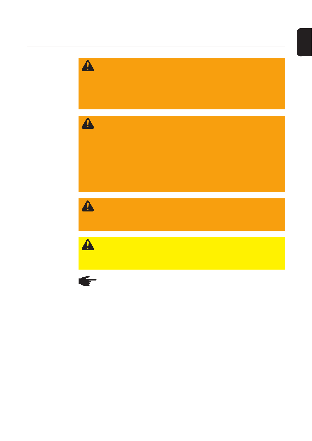
Lieferumfang
(1) Durchfluss-Sensor Pumpenteil
samt Schlauchgarnitur und Aufnahme Temperatur-Sensor
(2) Kabelbaum (2 Stk. )
(3) Kabelbinder kurz (2 Stk.)
(4) Kabelbinder lang (2 Stk.)
(5) Schlauchklemmen (3 Stk.)
(6) Schraube TX20
(6) (2)(5) (4) (3) (1)(7)(8)
(7) Durchfluss-Sensor Kühlerteil
samt Schlauchgarnitur
(8) CFM (2 Stk.)
Benötigtes Werkzeug
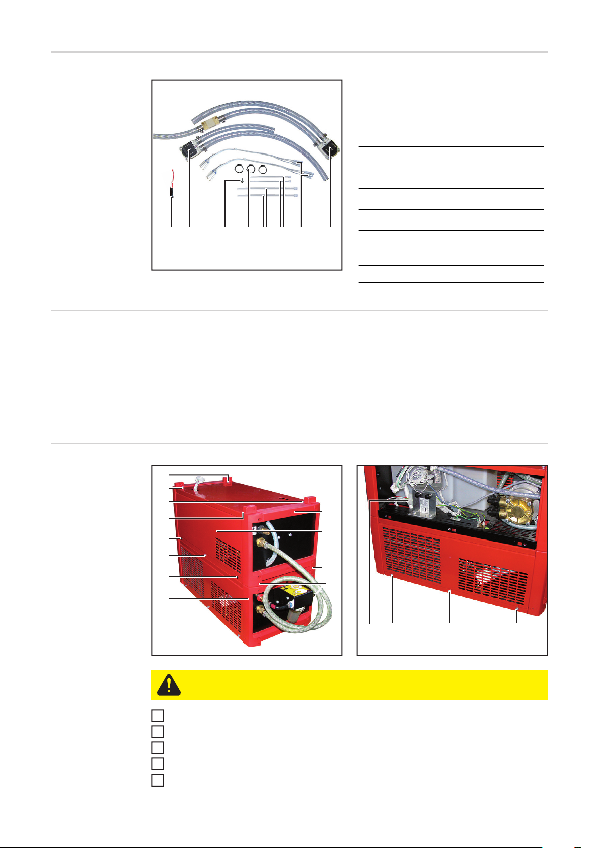
Vorbereitungen
- Torx-Schraubendreher TX 25
- Torx-Schraubendreher TX 20
- Schlitz-Schraubendreher klein
- Gabelschlüssel SW 21
- Seitenschneider
- Ötiker-Zange (oder Beißzange)
zum Verpressen der Schlauchklemmen
- Molex Ausziehwerkzeug
(1)
(2)
(3)
(4)
(5)
(6)
(7)
(8)
(12)
(11)
(10)
(9)
(14) (15) (16)
(13)
VORSICHT! Verbrühungsgefahr durch heißes Kühlmittel. Die Kühlmittel-Anschlüsse nur in abgekühltem Zustand des Kühlmittels abstecken.
Alle Kühlmittel-Anschlüsse von beiden Teilen des FK 9000 R abstecken
1
FK 9000 R von der Stromquelle trennen
2
3 Schrauben TX25 (5) - (7) entfernen und seitliche Abdeckung (11) abnehmen
3
Molex-Steckverbindung (13) trennen
4
4 Schrauben TX25 an der Rückseite (9) + (10) und an der Vorderseite entfernen
5
2
Page 5

Kühlerteil und Pumpenteil des FK 9000 R voneinander trennen
6
8 Schrauben TX25 (1) - (4) bei Pumpenteil und Kühlerteil entfernen und obere Abde-
7
ckungen abnehmen
6 Schrauben TX25 (14) - (16) auf beiden Seiten des Kühlerteils entfernen und seitliche
8
Abdeckungen abnehmen
DE
3
Page 6
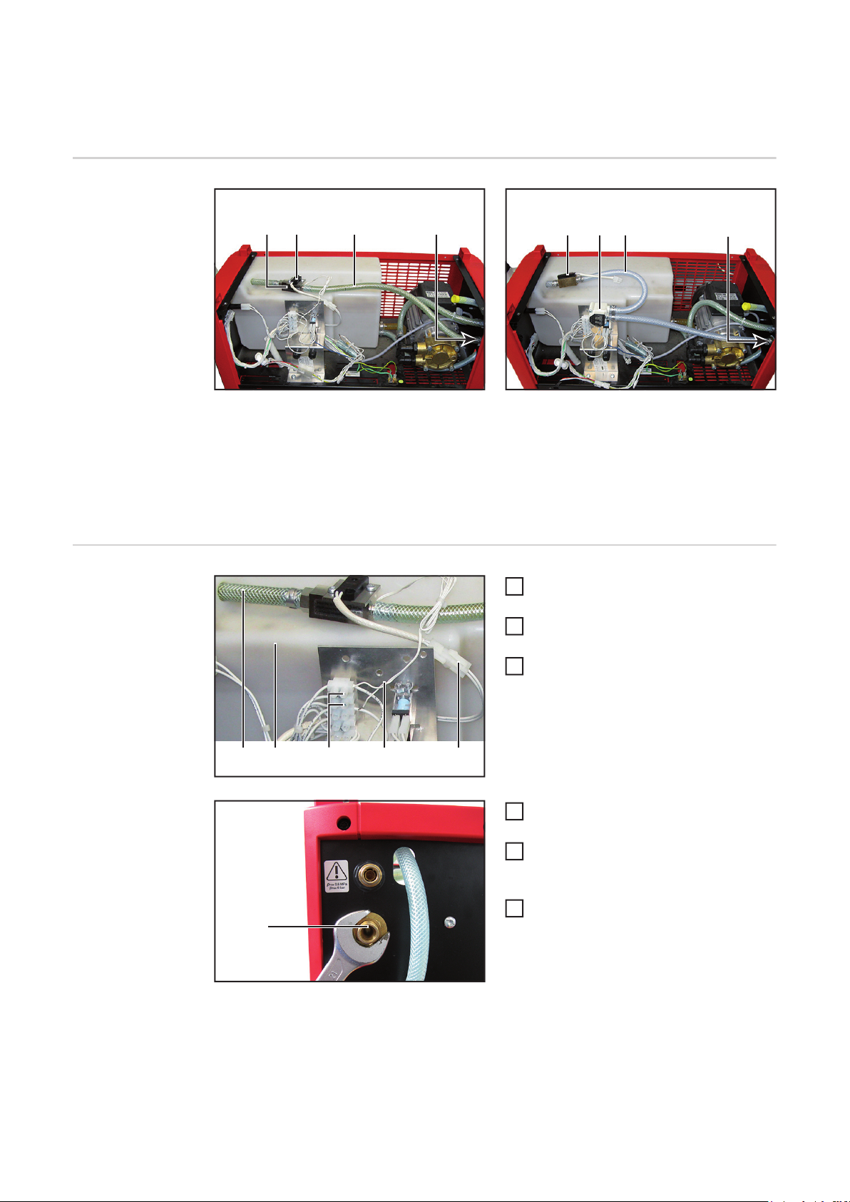
Durchfluss-Sensor im Pumpenteil FK 9000-R wechseln
Übersicht Umbau
Alten DurchflussSensor ausbauen
(3) (4)(2)(1)
Vor Umbau Nach Umbau
Beim Umbau wird der alte Durchfluss-Sensor (1) samt Schlauchgarnitur (3) durch den neuen Durchfluss-Sensor (5) mit Schlauchgarnitur (6) ersetzt.
Der Temperatur-Sensor (2) und der Anschluss Kühlmittel-Rücklauf (4) des alten Durchfluss-Sensors werden dabei am neuen Durchfluss-Sensor wieder verwendet.
Kabel des Durchfluss-Sensors (2) von
1
den Klemmen (3) abschließen
Temperatur-Sensor mittels Steckver-
2
bindung (1) abschließen
Rücklauf-Schlauch (5) aus dem Tank
3
(4) ziehen
(6)(2) (5) (4)
(5) (4) (1)(3) (2)
Anschluss Kühlmittel-Rücklauf (6) mit
4
Gabelschlüssel SW 21 demontieren
Alten Durchfluss-Sensor samt
5
Schlauchgarnitur aus dem Gerät entnehmen
Anschluss Kühlmittel-Rücklauf (6) von
6
(6)
4
altem Rücklauf-Schlauf demontieren
Page 7

Neuen Durchfluss-Sensor vorbereiten
1
(1) (7)(6)(2) (4)(3) (5)
4
3
Temperatur-Sensor (1) von altem
2
1
Durchfluss-Sensor (2) abnehmen
Klebeband (7) von neuem Durchfluss-
2
DE
Sensor (6) abziehen
Temperatur-Sensor (1) auf die Aufnah-
3
me Temperatur-Sensor (6) stecken
Schlauchklemme (4) über neuen
4
Rücklauf-Schlauch (5) schieben
Anschluss Kühlmittel-Rücklauf (3) vom
5
alten Rücklauf-Schlauch auf den neuen Rücklauf-Schlauch (5) montieren
Schlauchklemme (4) mit Ötiker-Zange
6
(oder Beißzange) verpressen
Neuen Durchfluss-Sensor einbauen
(4)(3)(2)
(1) (5)
(8)(7)(6)
2 Schrauben TX25 (1) lösen
1
Durchfluss-Sensor (3) mit Schraube
2
TX20 (4) auf Halteblech (2) wie dargestellt festschrauben
Halteblech (2) mit 2 Schrauben TX25
3
(1) wieder festschrauben
Anschluss Kühlmittel-Rücklauf (5) mit
4
Gabelschlüssel SW 21 wie angegeben
einbauen:
- Anschluss Kühlmittel-Rücklauf
- Zahnscheibe
- Gehäuse-Rückwand
- Messingscheibe
- Messingmutter
Rücklauf-Schlauch (6) so weit in den
5
Tank (8) stecken, dass er wie abgebildet im Einfüllstutzen (7) sichtbar ist
5
Page 8

Neuen Durchfluss-Sensor anschließen
(1)
(2)
(3)
(4)
(5)
(6)
(8)
(9)
(10)
(11)
Molexstecker (2) des Temperatur-Sen-
1
sors (1) mit dem selben Kabel verbinden an das auch der TemperaturSensor des alten Durchfluss-Sensors
angeschlossen war
Mit dem beiliegenden Kabelbaum die
2
Kontakte (4) - (6) des Durchfluss-Sensors (3) mit den Klemmen (8) - (10)
verbinden:
- (4) => X1.2 - GND => (9)
- (5) => X1.1 - Signal => (8)
- (6) => X1.4 - 24V => (10)
Kabelbaum wie abgebildet mit kleinem
3
Kabelbinder (11) bündeln und befestigen
6
Page 9

Durchfluss-Sensor im Kühlerteil FK 9000-R wechseln
Übersicht Umbau
(2) (3)(1)
Vor Umbau Nach Umbau
Beim Umbau wird der alte Durchfluss-Sensor (1) samt Schlauchgarnitur (2) durch den neuen Durchfluss-Sensor (4) mit Schlauchgarnitur (5) ersetzt.
Der Anschluss Kühlmittel-Rücklauf (3) des alten Durchfluss-Sensors wird dabei am neuen
Durchfluss-Sensor wiederverwendet.
(5)(4) (3)
DE
Durchfluss-Sensor wechseln
(1)
(3)
(2) (5)(4)
Schlauchklemme (1) mit Seitenschnei-
1
der entfernen und Rücklauf-Schlauch
abziehen
Kabel (3) des Durchfluss-Sensors von
2
den Klemmen (2) abklemmen
Anschluss Kühlmittel-Rücklauf (5) mit
3
Gabelschlüssel SW 21 demontieren
Alten Durchfluss-Sensor samt
4
Schlauchgarnitur (4) aus dem Gerät
entnehmen
Anschluss Kühlmittel-Rücklauf (5) von
5
altem Rücklauf-Schlauf (4) demontieren
Schlauchklemme (6) über den kürze-
6
ren Schlauch des Durchfluss-Sensors
schieben
Anschluss Kühlmittel-Rücklauf (5) am
7
kürzeren Schlauch montieren und mit
(5)
(6)(7)(8)(9)
Schlauchklemme verpressen
7
Page 10

(10) (5)(12) (11)
(16)
Anschluss Kühlmittel-Rücklauf (5) mit
8
Gabelschlüssel SW 21 wie angegeben
einbauen:
- Anschluss Kühlmittel-Rücklauf (5)
- Zahnscheibe (10)
- Gehäuse-Rückwand
- Messingscheibe (11)
- Messingmutter (12)
Anderes Schlauchende (13) mit
9
Schlauchklemme (14) am Kühler anschließen
Mit dem beiliegenden Kabelbaum die
10
Kontakte (7) - (9) des Durchfluss-Sensors mit den Klemmen (15) - (17) des
Kühlgerätes verbinden:
- (7) => X1.2 - GND => (16)
- (8) => X1.1 - Signal => (17)
- (9) => X1.4 - 24V => (15)
Kabel des Duchfluss-Sensors mit klei-
11
nem Kabelbinder bündeln und befestigen
Schläuche des Duchfluss-Sensors mit
(13)(14)(15)
(5)
12
großen Kabelbindern (18) bündeln
Abschließende
Tätigkeiten
(17) (18)
Alten CFM (1) bei Kühlerteil und Pum-
1
penteil mit Molex-Ausziehwerkzeug
entfernen
Neuen CFM bei Kühlerteil und Pum-
(1)
Bei Kühlerteil und Pumpenteil:
3
- Obere Abdeckungen aufsetzen
- Seitliche Abdeckungen aufsetzen
- Abdeckungen mit Schrauben TX25 befestigen
Kühlerteil und Pumpenteil wieder miteinander und/oder mit der Stromquelle und der
4
Systemperipherie verbinden
Siehe Bedienungsanleitung FK 9000 R
Kühlgerät befüllen und entlüften
5
Siehe Bedienungsanleitung FK 9000 R
2
penteil anschließen
8
Page 11

General
Safety
WARNING! Incorrect operation or shoddy workmanship can cause serious injury
or damage. All functions described in this document may only be carried out by
trained and qualified personnel after they have fully read and understood the following documents:
- this document
- all the operating instructions for the system components, especially the safety rules
WARNING! An electric shock can be fatal. Before starting the work described below:
- turn the power source mains switch to the "O" position
- disconnect the power source from the mains
- ensure that the power source remains disconnected from the mains until all
work has been completed
Only carry out work on the device when the cooling unit has been disconnected
from the power source.
After opening the device, use a suitable measuring instrument to check that electrically charged components (e.g. capacitors) have been discharged.
WARNING! An inadequate ground conductor connection can cause serious injury or damage. The housing screws provide a suitable ground conductor connection for earthing the housing and must NOT be replaced by any other screws that
do not provide a reliable ground conductor connection.
EN
Scope of supply
CAUTION! Danger of scalding by hot coolant. Only carry out the work described
here when:
- the coolant has cooled to room temperature (+25°C, +77°F)
- all system components have cooled to room temperature (+25°C, +77°F)
NOTE! Make sure that no coolant enters the device. If there is any coolant on the
exterior of the cooling unit, remove it immediately.
(1) Flow sensor pump section
including hose fitting and temperature sensor holder
(2) Cable harness (2x)
(3) Cable tie, short (2x)
(4) Cable tie, long (2x)
(5) Hose clips (3x)
(6) TX20 screw
(6) (2)(5) (4) (3) (1)(7)(8)
(7) Flow sensor cooler section
including hose fitting
(8) CFM (2x)
9
Page 12

Tools required - TX25 Torx screwdriver
- TX20 Torx screwdriver
- Small slotted screwdriver
- Flat spanner, size 21
- Cutting pliers
- Ötiker pliers (or pincers)
for crimping the hose clamps
- Molex extractor tool
Preparations
(1)
(2)
(3)
(4)
(5)
(6)
(7)
(8)
CAUTION! Danger of scalding by hot coolant. Wait until the coolant has cooled
down before unplugging the coolant connections.
Unplug all coolant connections from both parts of the FK 9000 R
1
Disconnect the FK 9000 R from the power source
2
Undo the three TX25 screws (5) - (7) and remove the side panel (11)
3
Disconnect the Molex plug connection (13)
4
Remove the four TX25 screws on the rear (9) + (10) and on the front
5
Separate the cooler and pump sections of the FK 9000 R
6
Remove the eight TX25 screws (1) - (4) on the pump and cooler sections and remove
7
the upper covers
Remove the six TX25 screws (14) - (16) on both sides of the cooler section and re-
8
move the side panels
(12)
(11)
(10)
(9)
(14) (15) (16)
(13)
10
Page 13

Changing the flow sensor in the FK 9000-R pump
section
Conversion overview
Removing the old
flow sensor
(3) (4)(2)(1)
Before conversion After conversion
The conversion process involves replacing the old flow sensor (1) and hose fitting (3) with
the new flow sensor (5) and hose fitting (6).
The temperature sensor (2) and the coolant return connection (4) of the old flow sensor are
reused with the new flow sensor.
Disconnect cable of flow sensor (2)
1
from the terminals (3)
Disconnect temperature sensor using
2
plug connection (1)
Pull return hose (5) out of the tank (4)
3
(6)(2) (5) (4)
EN
(5) (4) (1)(3) (2)
(6)
Remove coolant return connection (6)
4
using a size 21 flat spanner
Take old flow sensor and hose fitting
5
out of the device
Remove coolant return connection (6)
6
from the old return hose
11
Page 14

Preparing the
new flow sensor
1
(1) (7)(6)(2) (4)(3) (5)
4
3
Take temperature sensor (1) off the old
2
1
flow sensor (2)
Peel adhesive tape (7) off the new flow
2
sensor (6)
Plug temperature sensor (1) onto the
3
temperature sensor holder (6)
Slide hose clamp (4) over the new re-
4
turn hose (5)
Fit coolant return connection (3) of the
5
old return hose onto the new return
hose (5)
Crimp hose clamp (4) using the Ötiker
6
pliers (or pincers)
Fitting the new
flow sensor
(4)(3)(2)
(1) (5)
(8)(7)(6)
Undo two TX25 screws (1)
1
Screw flow sensor (3) onto retaining
2
plate (2) as shown using TX20 screw
(4)
Tighten retaining plate (2) again using
3
2 TX25 screws (1)
Install coolant return connection (5)
4
using a size 21 flat spanner as indicated:
- Coolant return connection
- Tooth washer
- Housing rear panel
- Brass washer
- Brass nut
Push return hose (6) into the tank (8)
5
until it can be seen in the fill nozzle (7)
12
Page 15

Connecting the
new flow sensor
(1)
(2)
(3)
(4)
(5)
(6)
(8)
(9)
(10)
(11)
Connect Molex plug (2) of temperature
1
sensor (1) using the same cable that
was used to connect the temperature
sensor of the old flow sensor
Connect contacts (4) - (6) of flow sen-
2
sor (3) to terminals (8) - (10) using the
enclosed cable harness:
- (4) => X1.2 - GND => (9)
- (5) => X1.1 - Signal => (8)
- (6) => X1.4 - 24V => (10)
Bind and fasten the cable harness as
3
shown using a small cable tie (11)
EN
13
Page 16

Changing the flow sensor in the FK 9000-R cooler
section
Conversion overview
Changing the
flow sensor
(2) (3)(1)
Before conversion After conversion
The conversion process involves replacing the old flow sensor (1) and hose fitting (2) with
the new flow sensor (4) and hose fitting (5).
The coolant return connection (3) of the old flow sensor is reused with the new flow sensor.
Remove hose clamp (1) with cutting
(1)
(3)
(2) (5)(4)
1
pliers and pull off return hose
Disconnect cable (3) of flow sensor
2
from terminals (2)
Remove coolant return connection (5)
3
using a size 21 flat spanner
Take the old flow sensor and hose fit-
4
ting (4) out of the device
Remove coolant return connection (5)
5
from the old return hose (4)
(5)(4) (3)
14
Slide hose clamp (6) over the shorter
6
of the flow sensor hoses
Fit coolant return connection (5) to the
7
shorter hose and crimp with hose
clamp
(5)
(6)(7)(8)(9)
Page 17

Install coolant return connection (5)
8
using a size 21 flat spanner as indicated:
- Coolant return connection (5)
- Tooth washer (10)
(10) (5)(12) (11)
- Housing rear panel
- Brass washer (11)
- Brass nut (12)
Connect the other hose end (13) to the
9
cooler using hose clamp (14)
Connect contacts (7) - (9) of flow sen-
10
sor to terminals (15) - (17) of cooling
unit using the enclosed cable harness:
- (7) => X1.2 - GND => (16)
- (8) => X1.1 - Signal => (17)
- (9) => X1.4 - 24V => (15)
Bind and fasten the flow sensor cable
11
using a small cable tie
Bind flow sensor hoses together using
12
large cable ties (18)
EN
And finally...
(13)(14)(15)
(5)
(16)
(17) (18)
Remove old CFM (1) on the cooler and
1
pump sections using a Molex extractor
tool
Connect new CFM to cooler and pump
(1)
In the case of the cooler and pump sections:
3
- Position the upper covers
- Position the side panels
- Fasten covers using TX25 screws
Connect the cooler and pump sections to each other again and/or to the power source
4
and the system peripherals
See FK 9000 R operating instructions
Fill and bleed the cooling unit
5
See FK 9000 R operating instructions
2
sections
15
Page 18

FRONIUS INTERNATIONAL GMBH
Froniusplatz 1, A-4600 Wels, Austria
Tel: +43 (0)7242 241-0, Fax: +43 (0)7242 241-3940
E-Mail: sales@fronius.com
www.fronius.com
www.fronius.com/addresses
Under http://www.fronius.com/addresses you will find all addresses
of our Sales & service partners and Locations
 Loading...