

Page 1

/ Perfect Welding / Solar Energy / Perfect Charging
FlexTrack 45
8,045,565
Operating instructions
Spare parts list
EN
Welding carriage
42,0426,0205,EN V03-03032015
Page 2

Page 3

Dear reader,
Introduction
These operating instructions will help you familiarise yourself with the device. It is in
your interest to read these instructions carefully and to observe the directions contained
in them. This will prevent faults and incorrect operation or possible damage to installed
components.
Please also obey the safety rules; doing so will ensure greater safety when using the
product. Careful handling of the entire system will repay you with years of safe and reliable operation. These are essential prerequisites for excellent results.
3
Page 4

4
Page 5

Contents
General information 7
About this document ........................................................................................................................................ 9
Function of this document .......................................................................................................................... 9
Explanation of safety symbols .................................................................................................................... 9
Qualied technicians .................................................................................................................................. 9
Copyright .................................................................................................................................................... 9
General .......................................................................................................................................................... 10
Principle....................................................................................................................................................10
Device concept and applications .............................................................................................................. 10
Safety 13
Operational reliability and tips for the user .................................................................................................... 15
Proper use ................................................................................................................................................ 15
Foreseeable misuse ................................................................................................................................. 15
Conversions or modications ................................................................................................................... 15
Duty to instruct ......................................................................................................................................... 15
Operating instructions .............................................................................................................................. 16
Personal protective equipment ................................................................................................................. 16
Local regulations ...................................................................................................................................... 16
Spare parts, wearing parts and auxiliary materials .................................................................................. 16
Transportation and storage ......................................................................................................................17
Description of the welding carriage 19
Scope of supply ............................................................................................................................................. 21
Basic conguration ................................................................................................................................... 21
Accessories and options .......................................................................................................................... 22
Welding carriage components ....................................................................................................................... 23
Conguration: welding carriage with oscillation unit ................................................................................. 23
Conguration: welding carriage without oscillation unit ............................................................................ 24
Operating elements and connections ............................................................................................................ 25
Connections ............................................................................................................................................. 25
Control box operating elements ............................................................................................................... 26
Welding carriage operating elements ....................................................................................................... 26
Remote control elements ......................................................................................................................... 27
Rails and bridges ........................................................................................................................................... 29
Weights of rails and bridges ..................................................................................................................... 29
Fittings ...................................................................................................................................................... 29
Rigid rails..................................................................................................................................................30
Flexible rails ............................................................................................................................................. 30
Bridge types ............................................................................................................................................. 31
Structure of a bridge ................................................................................................................................. 31
Conguration: rail and guide rings ........................................................................................................... 32
Welding position and weld seam tracking .....................................................................................................34
Possible welding positions ....................................................................................................................... 34
Commissioning 37
Preparing the welding carriage ...................................................................................................................... 39
Installing the welding carriage with oscillation unit ................................................................................... 39
Replacing oscillation unit with adjustment unit ......................................................................................... 40
Preparing and installing rails ......................................................................................................................... 41
Number of bridges required ..................................................................................................................... 41
Installing the bridges ................................................................................................................................ 41
Straight rails ............................................................................................................................................. 42
5
Page 6

Installing the contact cams ....................................................................................................................... 42
Securing the rail structure ........................................................................................................................ 43
Closed ring rail ......................................................................................................................................... 43
Closed ring rail ......................................................................................................................................... 44
Rigid ring segments ................................................................................................................................. 45
Flexible ring segments ............................................................................................................................. 47
Commissioning the welding carriage ............................................................................................................. 48
Placing the welding carriage on a straight rail .......................................................................................... 48
Placing the welding carriage on a ring rail ............................................................................................... 49
Regulating the pressure rollers ................................................................................................................ 50
Disengaging the welding carriage ............................................................................................................ 51
Operation 53
Creating and saving welding programs ......................................................................................................... 55
Switching on system components ............................................................................................................ 55
Setting the welding carriage parameters .................................................................................................. 55
Selecting additional functions ................................................................................................................... 56
Saving a program ..................................................................................................................................... 57
Loading a welding program ...................................................................................................................... 58
Changing the units of measurement ........................................................................................................ 58
Work procedure ............................................................................................................................................. 59
Working with or without oscillation ...........................................................................................................59
Performing a test run ................................................................................................................................ 59
Starting the welding process .................................................................................................................... 60
Maintenance and disposal 61
Troubleshooting ............................................................................................................................................. 63
General.....................................................................................................................................................63
Basic requirements for the system to work .............................................................................................. 63
Event codes ............................................................................................................................................. 63
Error codes ............................................................................................................................................... 63
Maintenance .................................................................................................................................................. 64
Maintenance personnel ............................................................................................................................ 64
Maintenance record ................................................................................................................................. 64
Recommended lubricants ........................................................................................................................ 64
Maintenance intervals and procedures .................................................................................................... 65
Technical data 67
Technical data ...............................................................................................................................................69
FlexTrack 45 welding carriage .................................................................................................................69
Control box ............................................................................................................................................... 69
Oscillation unit .......................................................................................................................................... 69
Dimensions...............................................................................................................................................69
Rating plates ............................................................................................................................................ 70
Weights of rails and bridges ..................................................................................................................... 71
Ring rail settings table .............................................................................................................................. 72
Flexible rail segments settings table ........................................................................................................ 73
Spare parts, circuit diagram 75
Spare parts .................................................................................................................................................... 77
Spare parts, wearing parts and auxiliary materials .................................................................................. 77
Ordering details ........................................................................................................................................ 77
Circuit diagram .............................................................................................................................................. 85
6
Page 7

General information
7
Page 8

8
Page 9

About this document
Function of this
document
Explanation of
safety
symbols
These operating instructions explain how to commission and operate the device in
conjunction with the installed system components. Look after the operating instructions
carefully; they must always be to hand at the location where the device is being used.
They can be used as a reference should any operational or functional problems occur in
the future.
DANGER! Indicates immediate and real danger. If it is not avoided, death or
serious injury will result.
WARNING! Indicates a potentially dangerous situation. Death or serious injury
may result if appropriate precautions are not taken.
CAUTION! Indicates a situation where damage or injury could occur. Minor
injury and/or damage to property may result if appropriate precautions are not
taken.
NOTE! Indicates a risk of awed results and possible damage to the equip-
ment.
Qualied
technicians
Copyright
IMPORTANT! Indicates tips for correct operation and other particularly useful informa-
tion. It does not indicate a potentially damaging or dangerous situation.
Special care is required if you see any of the symbols shown.
- These operating instructions are designed for trained technicians or persons with
practical welding experience. Personnel must be trained through veriable regular
instruction.
- Maintenance and repair of the device may likewise only be carried out by trained
technicians and in compliance with the specied maintenance activities and maintenance intervals.
- The manufacturer accepts no liability for damage caused by insufcient knowledge of
how to use the device.
Copyright of these operating instructions remains with Fronius International GmbH. The
text and illustrations are all technically correct at the time of going to
print. Fronius reserves the right to make changes. The contents of the operating instructions shall
not provide the basis for any claims whatsoever on the part of the purchaser.
9
Page 10

General
Principle
Device concept
and applications
The FlexTrack 45 welding carriage is intended for welding of butt and llet welds in the
MIG/MAG or CMT process, with or without oscillation.
It can be used on rigid or exible rails and on rigid or exible guide rings.
The compact welding carriage can be used in a wide range of applications. Three different rail types are available to suit differing requirements and surface geometries.
The carriage is entirely remote-controlled, making it perfect for universal use.
STRAIGHT application:
FLEXIBLE application:
min. 1500 mm
min. 1100 mm
10
Page 11

Device concept
and applications
(continued)
RING application:
200 - 6060 mm
11
Page 12

12
Page 13

Safety
13
Page 14

14
Page 15

Operational reliability and tips for the user
Proper use
Foreseeable
misuse
The FlexTrack 45 welding carriage must only be used for welding butt and llet welds in
a horizontal or vertical welding position.
Any use above and beyond this purpose is deemed improper – the manufacturer shall not be responsible for any damage resulting from such
improper use.
The welding carriage can be used in the following welding processes:
- MIG/MAG process
- CMT process
Proper use also includes:
- Carrying out all maintenance work at the stipulated intervals
- Keeping a service book with the necessary information (date, operator, activities car-
ried out, etc.)
- Using the spare parts stipulated by Fronius
- Following all the instructions, particularly the safety instructions, in the operating
instructions
- Using this document in conjunction with the operating instructions for the integrated
system components (power source, etc.)
Any use other than for the intended purpose shall be deemed improper use. This includes:
- Riding on the welding carriage, transporting loads
- Using the exible (non-reinforced) rails on level surfaces
- Use above head height
- Hoisting processes (hoisting, manoeuvring of loads, animals or persons)
- Use as an aid to climbing
- Use as a tray for tools
- Use outside of the permitted technical operating limits (e.g. exceeding the max. per-
mitted load)
- Use in hazardous areas
Conversions or
modications
Duty to instruct Before they start work, the system operator must instruct or train all persons working with
Any unauthorised conversions or modications made to the welding carriage by the user
shall invalidate all liability or warranty obligations on the part of the manufacturer.
The electromagnetic characteristics of the welding carriage can be adversely affected by
additions or modications of any kind. No modications or upgrades should therefore be
undertaken without rst consulting the manufacturer and obtaining written approval.
the welding carriage in:
- the theoretical and practical aspects of operation
- the safety regulations.
IMPORTANT! The duty to instruct also applies in particular to those who only occasionally work with the welding carriage (e.g. during set-up, maintenance, etc.).
15
Page 16

Operating in-
structions
The operating instructions help you to use the welding carriage safely and efciently, and
must therefore be to hand at all times.
- Keep the various sections of the operating instructions at the location where the weld-
ing carriage is being used at all times.
- Clearly mark the place where the instructions are kept.
- Ensure that all persons working with the welding carriage know where the operating
instructions are located.
- The operating instructions will only be able to help you in the event of a problem if
they are at hand!
IMPORTANT! The manufacturer shall not be liable for any damage that arises from failure to observe the operating instructions.
Personal protective equipment
The operator alone is responsible for the immediate working environment.
The following safety measures must be put in place and employed:
- Welding goggles
- Welding shield
- Welding gloves
- Welding apparel
- Welding footwear
Local regulations In some countries, local statutory regulations may apply that are not included in these
operating instructions. It is the duty of the operator to be aware of and comply with any
local statutory regulations. This relates primarily to regulations concerning:
- Accident prevention
- Machine safety
- Protection of personnel (protective equipment)
- Environmental protection
- Electrical system
Spare parts,
wearing parts
and auxiliary
materials
Use of third-party spare and wearing parts may pose risks. Use approved Fronius original spare parts only.
The manufacturer cannot accept any liability for damage resulting from the use of spare
or wearing parts or auxiliary materials that are not approved by the manufacturer.
16
Page 17

Transportation
and storage
The complete system, including tool kit, is supplied in a specially designed metal transport box. The rails must be stored separately.
17
Page 18

18
Page 19

Description of the welding carriage
19
Page 20

20
Page 21

Scope of supply
Basic
conguration
(6)
(1)
(5)
(4)
(2)(7) (3)
(1) Control box
(2) FlexTrack welding carriage
(3) 2 connecting cables: 1x between carriage and control box, 1x between carriage
and remote control
(4) Hosepack holder
(5) Connecting cable, control box - power source
(6) Tool kit
(7) Remote control
21
Page 22

Accessories and
options
(8) Oscillation unit
(9) Adjustment unit
Torch holder, depending on welding process:
(10) FTH 18
(11) FTH 21
(8)
(10)
(11)
(9)
22
Page 23

Welding carriage components
Conguration:
welding carriage
with oscillation
unit
Carrying handles
Torch holder
Limit switch
Contact cam
Torch adjustment unit
Remote control
Oscillation unit
Rail
Coupling
Locking lever
Guide rollers
Hosepack
holder
Magnetic bridge
23
Page 24

Conguration:
welding
carriage without
oscillation unit
Hosepack
holder
Remote control
Carrying handles
Rail
Coupling
Limit switch
Magnetic bridge
Torch adjustment unit
Torch holder
Adjustment unit
24
Page 25

Operating elements and connections
Connections
4
3
1
2
5
(1) Control box mains cable
(2) Control line between welding carriage and control box
(3) Control line between welding carriage and remote control
(4) Connecting lead between control box and power source
(5) Connecting lead for oscillation unit
25
Page 26

Control box
operating
elements
Welding carriage
operating
elements
(1)
(1) ON/OFF switch
switches the control box on and off
(1)
(3)
(1) Coupling on/off
Locks/unlocks the welding carriage on the rail. Allows rapid positioning of the
carriage.
(2) Guide rollers locking lever
Fixes and releases the internal guide rollers.
(3) Limit switch (both sides, in and against direction of travel)
For automatic stopping or changing of direction.
(2)
26
Page 27

Remote control
elements
(1) (2)
(11)
(3a) (3b) (3c)
(10)
(9)
(8)
(1) Numerical display, 4 digits (metric / imperial)
Displays welding parameters and error codes.
(2) Limit switch function, change direction / stop
Depending on the switch position, the welding carriage changes direction or
stops as soon as the limit switch is activated.
(3a) White symbol: Oscillation dwell time, left
Regulates the oscillation dwell time on the left.
Yellow symbol: Return travel path
Return time at the end of the welding path in seconds [s].
(3b) White symbol: Oscillation dwell time, middle
Regulates the oscillation dwell time in the middle of the weaving motion.
Yellow symbol: Segment path with welding
Sets the length of the individual welding segments in [cm].
(3c) White symbol: Oscillation dwell time, right
Regulates the oscillation dwell time on the right.
Yellow symbol: Segment path without welding
Sets the distances between the individual segments in [cm].
(4) Oscillation speed
Regulates the oscillation speed.
(5) Offset
Regulates the offset during weaving.
(4)
(5)
(6)
(7)
27
Page 28

Remote control
elements
(continued)
(6) Traversing direction
Selects the traversing direction.
(7) Travel speed
Regulates the travel speed of the welding carriage.
(8) Welding mode
3 welding modes can be selected:
- Test
- Without arc (O)
- With arc (I)
(9) White symbols: Weaving mode
Four weaving modes can be selected:
- No weaving
- Trapezoidal weaving
- Box weaving
- Triangular weaving
Green marking: Preset path measurement
Preset to select the additional path measurement function (green symbol) on the
weaving path button (10).
Yellow marking: Preset segment welding
Preset to select the additional segment welding function (orange symbols).
IMPORTANT! The welding process cannot start until the weaving mode adjusting
knob (9) is set to one of the white function parameters.
(10) White symbol: Weaving path
Regulates the weaving path.
Green symbol: Total welding path
Total welding path in [cm].
(11) White symbol: End-crater lling time
Enables the weld seam to be nished smoothly.
IMPORTANT: Parameters must be entered via the power source and must be
either equal to or greater than the power source value.
Yellow symbol: Start-up delay / Flying-start
If value is positive – start-up delay [s]: Start welding -> Dwell time elapses ->
Carriage starts to move.
If value is negative – ying-start [s]: Carriage starts to move. The arc does not
ignite until the “ying start” time has expired.
28
Page 29

Rails and bridges
Weights of rails
and bridges
Magnetic bridge 2.5 kg
Vacuum bridge (on request) 1.6 kg
Magnetic bridge with spacers 2.7 kg
Vacuum bridge with spacers (on request) 1.8 kg
Magnetic bridge with spacer and metric calibration unit 3.4 kg
Magnetic bridge with metric calibration unit 3.2 kg
Bridge with adjustable foot, spacer and metric calibration unit 1.5 kg
Bridge with adjustable foot and metric calibration unit 1.3 kg
Vacuum bridge with spacer and metric calibration unit (on request) 2.6 kg
Vacuum bridge with metric calibration unit (on request) 2.4 kg
Rigid guide rail 1884 mm 11 kg
Flexible guide rail 1884 mm 5.5 kg
Flexible guide rail 1695 mm 4.8 kg
Flexible guide rail 1130 mm 3.3 kg
Rigid guide ring Ø200-300 mm 8.8 kg
Rigid guide ring Ø300-480 mm 11 kg
Rigid guide ring Ø480-660 mm 14 kg
Rigid guide ring Ø660-840 mm 16 kg
Rail segment Ø840-1020 mm 19 kg
Rail segment Ø1020-1200 mm 22 kg
Rail segment Ø1200-1380 mm 24 kg
Rail segment Ø1380-1560 mm 27 kg
Fittings
Joining elements:
Two joining elements to extend the rails
are included with every rail.
Contact cam installation kit:
Two contact cams to trigger the limit switch at the beginning and end of the guide rail.
IMPORTANT! If contact cams are not used, there is a risk that the welding carriage
might travel beyond the end of the rail and fall off.
29
Page 30

Rigid rails
STRAIGHT
► Straight rails with aluminium reinforce-
ment
► For horizontal and vertical use
► With two joining elements to extend
the rail
Length: 1884 mm
Weight: 5.5 kg
RING (external use)
► Rigid rails with aluminium reinforce-
ment
► For external use on pipes
The following sizes are available:
For workpiece Ø 200-840 mm:
► Guide ring, rigid 200-300 mm
► Guide ring, rigid 300-480 mm
► Guide ring, rigid 480-660 mm
► Guide ring, rigid 660-840 mm
Flexible rails
For workpiece Ø 840-1560 mm:
► Guide ring, rigid 840-1020 mm
► Guide ring, rigid 1020-1200 mm
► Guide ring, rigid 1200-1380 mm
► Guide ring, rigid 1380-1560 mm
STRAIGHT/CURVED
► Can be mounted on straight or curved
components
► Internal welding:
min. internal radius 1500 mm
► External welding:
min. external radius 1100 mm
RING (internal and external use)
► From external diameter >1560 mm to
6060 mm
30
Different segment lengths for different
diameter ranges:
Segment type Length
I 1130 mm
II 1695 mm
III 1884 mm
Page 31

Bridge types
Magnetic bridge Bridge with adjustable feet
Structure of a
bridge
For magnetic components, heat-resistant
to 180°C.
Recommended for rigid rings up to 840
mm in diameter.
The magnetic force is controlled by a
lever.
Maximum holding force of a magnetic
bridge: 750 N
IMPORTANT! All bridges include a metric adjustment unit and a distance block.
Standard bridge with magnetic feet
Bridge with distance block
Standard bridge
Screws M6x20
Metric adjustment unit
(option)
Adjusting screw
M12x3
Bridge with metric
adjustment unit
Screws M6x20
Bridge with metric adjustment unit
and distance block
M6x14 screws
Screws M6x20
31
Page 32

Structure of a
l=1130 mm
Ø 1560 - 6060 mm
bridge
(continued)
Bridge with adjustable feet
Bridge with adjustable foot and
metric adjustment unit
M6x14 screws M6x14 screws
Bridge with adjustable foot, metric adjustment unit and distance block
M6x14 screws
Conguration:
rail and guide
rings
on request
on request
Ø200-840mm
Ø 840 - 1380mm Ø 1380 - 1560 mm
32
Page 33

Conguration:
rail and guide
rings
(continued)
on request
Ø 1560 - 6060 mm
l=1130 mm
l=1695 mm
l=1884 mm
33
Page 34

Welding position and weld seam tracking
Possible welding
positions
IMPORTANT! In vertical applications, the rail structure must be secured by a load arres-
tor with a locking function to prevent it from falling.
The load arrestor must be designed for the total weight of the welding carriage and rail
structure. The manufacturer accepts no liability for any damage to persons or property
resulting from vertical use of the welding carriage without a load arrestor.
Horizontal position on rigid rail:
Possible welding positions:
- PA (at position)
- PB (horizontal-vertical position)
- PC (horizontal position)
Vertical position on rigid rail:
Possible welding positions:
- PG (descending position)
- PF (ascending position)
34
Page 35

Possible welding
positions
(continued)
Positions on exible rail:
Possible welding positions:
- PA (at position)
- PB (horizontal-vertical position)
- PC (horizontal position)
PG (descending position)
- PF (ascending position)
Positions on ring rail (rigid or exible)
Possible welding positions:
- PA (at position)
- PB (horizontal-vertical position)
- PC (horizontal position)
PG (descending position)
- PF (ascending position)
35
Page 36

36
Page 37

Commissioning
37
Page 38

38
Page 39

Preparing the welding carriage
Installing the
welding carriage
with oscillation
unit
7
5
3
6
4
2
1
Assembling the welding carriage with oscillation unit:
1. Connect the oscillation unit to the welding carriage using the six screws supplied.
2. Connect the connecting lead for the oscillation unit to the carriage and lock it in
place.
3. Push the welding torch holder onto the oscillation unit.
4. Tighten the screws.
5. Fit the horizontal support onto the welding torch holder and tighten the screws.
6. Feed in the hosepack holder and x it in place with the clamp lever.
7. The remote control has a magnet which can be used to attach it to the welding
carriage.
39
Page 40

Replacing
oscillation unit
with adjustment
unit
1
3
2
Replacing the oscillation unit with an adjustment unit:
1. Disconnect the connecting lead for the oscillation unit from the welding carriage.
2. Undo the six M6 screws and remove the oscillation unit.
3. Place the protective cap onto the socket for the oscillation unit.
4. Fasten the adjustment unit to the welding carriage using four M6 screws.
IMPORTANT! Reverse this sequence when replacing the adjustment unit with the
oscillation unit.
4
40
Page 41

Preparing and installing rails
Number of
bridges required
Installing the
bridges
Straight, rigid rails:
► For a rail length of 1884 mm: use 3 bridges.
Straight, exible rails:
► For a rail length of 1884 mm: use 5 bridges.
► For a rail length of 1695 mm: use 4 bridges.
► For a rail length of 1130 mm: use 3 bridges.
Closed ring rails and ring rails made from rail segments:
► The number of bridges required depends on the ring diameter and should be taken
from the settings table.
Bridge without spacer and calibration unit:
Install the bridge on the rail using the two M6x65 screws and counter them with the two
M6 nuts.
IMPORTANT! The bridge installation positions on the rail are indicated by the hole in
the middle of the rail for the adjusting screw on the calibration unit.
Screw
M6x65
Nut M6
Bridge with adjustment unit:
Bridges with an adjustment unit are installed with the M6x14 screws supplied.
M6x14 screws
Screw
M4x10
41
The scale on the side of the adjustment
unit is xed in place using the M4x10
screw supplied.
Page 42

Straight rails Both rigid and exible straightw rails can easily be extended using the joining elements
supplied.
(3)
(4)
(1)
(2)
1. Set the levers on the magnetic bridges (1) to OFF.
2. Place the rail section on the workpiece and set the levers on the magnetic bridges
to ON.
3. Fit the joining element (2) at the end of the straight rail.
4. Loosen both M6 screws (3).
5. On the next section of rail, set the levers on the magnetic bridges to OFF.
6. Push the next section of rail with the groove (4) between the joining element (2)
and the screw (3).
7. Tighten both M6 screws (3).
8. Align the rail if necessary, then set the levers on the magnetic bridges to ON.
9. Install further rail sections as described above until the rail has reached the required length.
10. Install a contact cam for the limit switch at the beginning and end of the rail.
Installing the
contact cams
IMPORTANT! If contact cams are not used, there is a risk that the welding carriage
might travel beyond the end of the rail and fall off.
In rail structures with open ends (not rings), contact cams (limit switch installation kit)
must be installed at both ends.
42
Page 43

Securing the rail
structure
IMPORTANT! In vertical applications, the rail structure must be secured by a load arres-
tor with a locking function to prevent it from falling.
The load arrestor must be designed for the total weight of the welding carriage and rail
structure. The manufacturer accepts no liability for any damage to persons or property
resulting from vertical use of the welding carriage without a load arrestor.
NOTE! Ensure that the cable on the load arrestor is kept permanently taut.
Closed ring rail
The closed ring rail is used for welding of pipes with a diameter of 200 to 840 mm.
Install the recommended number of bridges on the guide ring.
For the number of bridges, refer to the table below:
DIAMETER SEGMENTS BRIDGES
200 - 300 mm (7.9 - 11.8 in.) 2 3
300 - 480 mm (11.8 - 18.9 in.) 2 4
480 - 660 mm (18.9 - 26 in.) 2 6
660 - 840 mm (26 - 33.1 in.) 2 8
(a)
1. Open the locks on the ring rail:
- Loosen the M6 screws (a)
- Release the locking hook (b)
(b)
2. When using magnetic bridges: Set the levers on the magnetic bridges to OFF.
3. Using the adjusting screw (c), set the distance on the calibration units on the
bridges. Refer to the settings table for the recommended setting M plus 3 mm.
(c)
43
Page 44

Closed ring rail
4. Install the ring rail on the component.
5. Engage the locking hook (a), tighten the screws (b).
6. Using the adjusting screws (c) on the bridges, t the ring rail evenly around the
component.
(c)
(c)
(c)
7. When using magnetic bridges: Set all the levers on the magnetic bridges to the
ON position.
44
Page 45

Rigid ring
segments
Rigid ring segments can be joined to create guide rings with a maximum diameter of
1560 mm (4 segments). The individual segments are joined to form a guide ring using
locking catches and M6x20 socket screws:
1. Join two rail segments. Tighten the top
four M6x20 screws (a) slightly.
2. Lock the locking hook (b) on the lower
guide section.
Tighten the two lower M6x16 screws
(c) slightly.
(b)
(a)
(a)
(c)
3. Engage the upper locking hook (d). 4. If necessary, align the two segments
with one another.
Tighten all the M6 screws (4 at the top,
2 at the bottom).
The number of segments used and the bridges required for different pipe diameters are
set out in the table below:
DIAMETER SEGMENTS BRIDGES
840 - 1020 mm (33.1 - 40.2 in.) 3 9
1020 - 1200 mm (40.2 - 47.2 in.) 3 12
1200 - 1380 mm (47.2 - 54.3 in.) 3 15
1380 - 1560 mm (54.3 - 61.4 in.) 4 16
45
Page 46

Rigid ring
segments
(continued)
1. It is recommended that two people should work together when installing a guide
ring made from rail segments.
2. When using magnetic bridges: Set the lever on the bridges to OFF.
3. Use the adjusting screw (d) to set the distance on the calibration units on the
bridges. For the recommended setting M, please refer to the settings table. When
installing the rings, set them initially to 3 mm more than is shown on the calibration unit.
(d)
4. Install the guide ring on the component.
5. Using the adjusting screws (d) on the bridges, t the guide ring evenly around the
component.
6. When using magnetic bridges: set all the levers on the magnetic bridges to ON.
46
Page 47

Flexible ring
segments
Flexible ring segments can be joined to create guide rings with a diameter of 1560 mm
to 6060 mm (up to 11 segments). The individual segments are joined to form a guide ring
using M6x20 socket screws.
Flexible segments are available in the following lengths:
SEGMENT
LENGTH
TYPE
Type I 1130 mm
Type II 1695 mm
Type III 1884 mm
The number of segments depends on the pipe diameter and can be selected using the
table below:
Diameter Segments Bridges
1560 - 1740 mm
1740 - 1920 mm
1920 - 2100 mm
2100 - 2280 mm
3x type I
1x type II
3x type III
1x type I
3x type III
1x type II
3x type III
2x type I
18
18
20
21
2280 - 2460 mm 5x type II 25
2460 - 2640 mm
2640 - 2820 mm
3x type III
2x type II
5x type II
1x type I
25
25
2820 - 3000 mm 6x type II 28
3000 - 3180 mm
3x type III
3x type II
30
3180 - 3360 mm 6x type III 30
3360 - 3540 mm 7x type II 33
3540 - 3720 mm
3720 - 3900 mm
6x type III
1x type I
6x type III
1x type II
33
35
Diameter Segments Bridges
3900 - 4080 mm
6x type III
2x type I
36
6x type III
4080 - 4260 mm
1x type II
38
1x type I
4260 - 4440 mm
6x type III
2x type II
40
6x type III
4440 - 4620 mm
1x type II
41
2x type I
6x type III
4620 - 4800 mm
2x type II
43
1x type I
4800 - 4980 mm
6x type III
3x type II
45
4980 - 5160 mm 9x type III 45
6x type III
5160 - 5340 mm
3x type II
48
1x type I
5340 - 5520 mm
5520 - 5700 mm
5700 - 5880 mm
9x type III
1x type I
9x type III
1x type II
9x type III
2x type I
48
50
51
9x type III
5880 - 6060 mm
1x type II
53
1x type I
47
Page 48

Commissioning the welding carriage
Placing the
welding carriage
on a straight rail
1. Remove the remote control. The welding carriage must be installed on the guide
rail without the remote control.
2. Coupling and levers for the rollers in the "OFF" position.
3. Lift the welding carriage using the handles and place it on the rails.
4. Set the lever for the moving pressure rollers to the "ON" position.
5. Set the lever for the stationary pressure rollers to ON. (Reverse the procedure for
removal).
6. Manually pull the welding carriage along the full length of the rail once to check
whether the welding torch remains at a constant distance from the workpiece. If
the distance is not constant, set the correct distance "M" on the relevant bridges.
7. Push the welding carriage along the rail. At the same time, set the coupling to the
"ON" position to engage the gearbox unit with the openings on the guide rail.
8. Check the following switches on the remote control:
- Welding mode switch in position "0"
- Change direction / stop switch in the central position.
9. Connect the cables:
- Plug in the connecting lead to the power source (1) at the control box and
power source.
- Connect the remote control to the control box using the control line (2) (purple
cable).
- Connect the welding carriage to the control box using the control line (3) (purple cable).
- Connect the control box to the grid (4).
10. Set the mains switch on the control box to ON.
1
2
4
3
48
Page 49

Placing the
welding carriage
on a ring rail
1. Remove the remote control. The welding carriage must be installed on the guide
rail without the remote control.
2. Coupling and levers for the rollers in the "OFF" position.
3. Loosen the three M6x20 holding the pressure rollers in place, on both sides.
4. Place the welding carriage horizontally on the rail above the centre of the workpiece and hold it by the handle.
5. Set the lever for the moving pressure rollers to the "ON" position.
6. Set the lever for the stationary pressure rollers to ON. (Reverse the procedure for
removal).
7. Tighten the three M6 mounting screws on both sides.
8. Manually pull the welding carriage along the full length of the rail once to check
whether the welding torch remains at a constant distance from the workpiece. If
the distance is not constant, set the correct distance "M" on the relevant bridges.
9. Push the welding carriage along the rail. At the same time, set the coupling to the
"ON" position to engage the gearbox unit with the openings on the guide rail.
10. Check the following switches on the remote control:
- Welding mode switch in position "0"
- Change direction / stop switch in the central position.
49
Page 50

Placing the
welding carriage
on a ring rail
(continued)
11. Connect the cables:
- Plug in the connecting lead to the power source (1) at the control box and
power source.
- Connect the remote control to the control box using the control line (2) (purple
cable).
- Connect the welding carriage to the control box using the control line (3) (purple cable).
- Connect the control box to the grid (4).
12. Set the mains switch on the control box to ON.
Regulating the
pressure rollers
The four pressure rollers are non-positively connected with the guide rails by means of
disk springs.
IMPORTANT! The minimum play of 0.6 mm (maximum force) is achieved by tightening
the M8 screw to its maximum extent and then loosening it by a half turn.
The pressing force of the rollers is set as follows:
1. Loosen the M8 nuts (a).
2. Tighten the M8 adjusting screws
(b) to their maximum extent. Then
release them by a half turn.
3. Tighten the M8 nuts (a).
(b)
(a)
(b)
(a)
50
Page 51

Disengaging the
welding carriage
To attain optimum wirefeed, observe the following when laying the hosepack:
- Do not kink the hosepack
- Always lay the hosepack as straight as possible
1. Undo the knurled screw (a) on the
clamp.
(a)
2. Insert the hose pack as illustrated
IMPORTANT! Do not kink the hosepack. This can cause wirefeed problems.
3. Tighten the knurled screw (a)
NOTE! Observe the maximum tensile load on the hosepack holder (see the
"Technical data" section). This value must not be exceeded.
51
Page 52

52
Page 53

Operation
53
Page 54

54
Page 55

Creating and saving welding programs
Switching on
system
components
Setting the
welding carriage
parameters
WARNING!
Danger of injury from premature arc ignition.
The arc may be ignited accidentally. This can cause serious eye injuries.
- Before switching on the system components, ensure that the "Welding
mode" toggle switch on the welding carriage remote control is set to the "O"
position.
IMPORTANT! There are no xed rules for the sequence in which the system components are switched on. They can be switched on in any order.
On the following system components turn the main switch to the "ON - 1" position:
- Welding carriage control box
- Power source
- Wire-feed unit (if power is not supplied from the power source)
NOTE! The oscillation unit must be connected to the welding carriage when
saving programs with weaving parameters.
The remote control can be used to congure 9 welding programs with the following parameters:
With oscillation:
- Travel speed
- Weaving path
- Oscillation speed
- Dwell time, left
- Dwell time, middle
- Dwell time, right
- End-crater lling time
Without oscillation:
- Travel speed
- End-crater lling time
To set a parameter, turn the corresponding adjusting knob:
to the right to increase the value
to the left to reduce the value
When a setting has been adjusted, the value of the parameter is shown on the display.
Press the adjusting knob to save the value for the setting.
Additional functions:
- Path measurement (green markings)
- Segment welding (yellow markings)
55
Page 56

Selecting
additional
functions
IMPORTANT! After adjusting settings for the additional functions, turn the weaving mode
knob (1) back to the weaving mode required (white markings), otherwise the welding
process cannot start.
Additional function - path measurement:
1. Set the weaving mode knob to the GREEN marking.
2. Turn the weaving path knob and set the welding path required.
3. Turn the knob back to the white function parameter required.
Additional function - segment welding:
1. Set the weaving mode knob to the YELLOW marking.
2. Set the segment welding function parameter:
Start-up delay / ying-start:
If value is positive – start-up delay [s]: Start welding -> Dwell
time elapses -> Carriage starts to move.
If value is negative – ying-start [s]: Carriage starts to move.
The arc does not ignite until the “ying start” time has expired.
Return travel path:
Return time at the end of the welding path.
Segment path with welding:
Length of the individual welding segments.
Segment path without welding:
Length of the distances between the individual welding segments.
56
Page 57

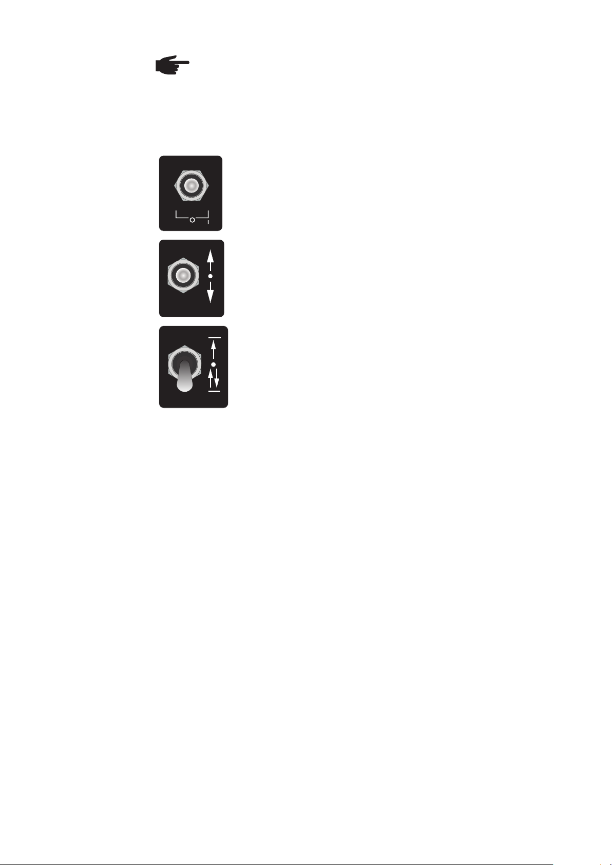
Saving a program
Before saving a program:
Set the toggle switch for the "Change direction/stop" limit switch
functions to the lower position (change direction).
Set the welding mode toggle switch to the 0 position.
TEST
Set the traversing direction toggle switch to the central position 0.
Saving a program:
- Press the travel speed knob and end-crater lling time knob at the same time and
hold for 4 seconds.
- memX appears on the display. X stands for the program number that has not yet
been selected.
- Turn the travel speed knob to select the program number required.
- Press the travel speed knob to save the program with this number.
57
Page 58
Loading a
welding program
NOTE! The remote control has a factory-saved, read-only program "mem0",
which contains the working parameters for the welding carriage and oscillation
unit.
The value “mem0” cannot be overwritten.
To load a saved program, "mem" and the number of the last used program must be
shown on the display.
Set the welding mode toggle switch to the 0 position.
TEST
Set the traversing direction toggle switch to the central position 0.
Set the change direction/stop toggle switch to the change direction
position.
Changing the
units of
measurement
Press the travel speed button and the weaving path / total
welding path button at the same time for at least 4 seconds.
Turn the travel speed button to select a program.
To load the program selected, press the travel speed button briey
once.
Measurements can be displayed in either metric (cm) or imperial (inch) units.
To change the units, proceed as follows:
- Set the main switch on the control box to 0 (off).
- Press and hold the left and right dwell time buttons at the same time.
- Switch on the main switch on the control box. The unit of measurement selected (cm
or inch) is shown on the display.
- Select the setting required using the travel speed knob.
- Press the travel speed knob once to conrm and apply the setting.
58
Page 59

Work procedure
Working with
or without
oscillation
Performing a test
run
The welding carriage can work with and without oscillation. If the oscillation unit is not
required, it should be removed according to the instructions in the "Preparing the welding
carriage " section under "Replacing the oscillation unit with an adjustment unit".
After the control box has been switched on, it automatically checks whether the oscillation unit is connected and the current status appears on the display.
Perform a test run to check that all system components are working together correctly.
The test run is carried out without an arc and allows you to check all the movements during the program sequence.
Set the welding mode toggle switch to the 0 position.
TEST
Move the traversing direction toggle switch forwards.
The welding carriage moves according to the programmed parameters, but without welding.
The welding carriage's current speed is then shown on the display.
All parameters can be changed during operation.
When the welding carriage reaches the limit switch:
If the change direction/stop toggle switch is forwards or in the central position:
► The welding carriage stops when it triggers the limit switch.
If the toggle switch is in the change direction position:
► After triggering the limit switch, only the oscillation unit stops
and the welding carriage starts to move back in the opposite
direction. In this situation, the travel speed can be increased
to the maximum for the return journey: press the travel speed
knob and hold for 2 seconds.
NOTE! If the traversing direction toggle switch is in the central position and the
welding mode toggle switch is in the "test" position, this position causes the
arc to light up briey. To activate the welding function, move the welding mode
toggle switch to the "I" position.
59
Page 60

Starting the
welding process
Set the welding mode toggle switch to the "I" position.
TEST
Set the change direction/stop toggle switch to the position required.
Set the traversing direction toggle switch to the position required
(forwards or backwards). The welding process starts.
IMPORTANT! Never leave the device unattended during the welding process.
To stop the welding carriage early, move the traversing direction
toggle switch to the central position.
60
Page 61

Maintenance and disposal
61
Page 62

62
Page 63

Troubleshooting
General
Basic
requirements for
the system to
work
Event codes
In the event of faults, note that the functioning of the entire system depends on many
additional components (power source, wire-feed unit, etc.) that are also potential sources
of problems.
If an error occurs, "Err" and the error number are shown on the display.
► Connections have been established between the separate system components
► System components are supplied with electricity and the mains voltage for each
component complies with the rating plate.
Indication Description Remedy
cLs- / cLs+ Welding carriage has reached one
of the contact cams on the rail.
oLs- / oLs+ The oscillation arm has reached a
limit position.
cm Metric system selected. To change the setting: see the "Cre-
inch Imperial system selected.
mem0 mem9
Save or load a
welding program.
Release the limit switch using the
traversing direction toggle switch.
Release the limit switch using the
offset knob.
ating and saving welding programs"
section under "Changing the units
of measurement".
--
Error codes
Indication Description Remedy
err1 Error during initiation of the CAN
communication system.
err2 Communication error between car-
riage and remote control.
err3 Communication error between re-
mote control and oscillation unit.
err4 Communication error between
remote control and control box.
err5 Error while saving or reading,
memory error on the remote control.
err6 Operating temperature exceeded
or ambient temperature too high.
err7 Error in motor control unit. Contact your FRONIUS service
err8 Error in oscillation control unit. Contact your FRONIUS service
err9 Error in the control unit in the con-
trol box.
Rectify short circuit between the
lines or communication ports.
Check connections, tighten if necessary.
If necessary, replace damaged
control lines.
Contact your FRONIUS service
engineer.
Allow device to cool down. Operate
in a lower ambient temperature.
engineer.
engineer.
Contact your FRONIUS service
engineer.
63
Page 64

Maintenance
Maintenance
personnel
WARNING!
Risk of injury and damage if maintenance work is not carried out correctly.
It is essential to adhere to the maintenance intervals and maintenance procedures. The manufacturer accepts no liability for any damage caused by inadequate or poorly performed maintenance.
- All maintenance work on the welding carriage must be carried out by trained
technicians.
Electrically qualied person / technician:
Is a person who is able to evaluate the working steps, based on his specic technical
training, experiences and the well known relevant standards / regulations to recognize
possible risks / hazards.
Electrically instructed person:
Is a person who was trained by an electrically qualied person and was instructed
of the possible risks that can appear due to improper use / behaviour as well as the
necessary protective measures.
Notice: instruction has to be recorded
Electrically ordinary person:
Is a layperson who is neither an electrically qualied person nor a electrically instructed
person.
Maintenance
record
Recommended
lubricants
The following measures regarding maintenance must be put in place by the system
operator:
- a service book containing the required information (date, operator, maintenance work
carried out) must be kept.
IMPORTANT! Lubricants with solid lubricant additives (e.g.: MoS2, graphite and PTFE)
are not suitable for guiding systems.
Lubricant DIN DIN number Comment
Grease KP 2-K 51502 / 51825 Lithium soap grease
Lubricating oil CLP32-100 51517 Part 3 ISO VG 32-100
64
Page 65

Maintenance
intervals and
procedures
NOTE! Use a dry cleaning cloth to clean the machine components. Only
use a cleaning agent if this is indicated in the maintenance procedure for a
specic part.
Item Component Procedure Interval
Linear guides Clean, check oil lm M
A
Gearbox Clean, regrease M
B
Rack and pinion Clean, regrease M
C
Rollers, underbody & rails Clean, check position M
D
Safety devices:
E
Function test D
- Limit switch
Grease nipples Regrease M
F
Connection contacts Cleaning W
G
D Daily
W Weekly
M Monthly
1/2 y Half-yearly
Y Yearly
Daily care:
After every use:
► Remove the welding carriage from the guide rail.
► Using a brush or a soft cloth, clean the guide rails for the oscillation unit, the guide
rollers and the gearbox.
► Carry out maintenance work as shown in the illustration below.
IMPORTANT! Do not use compressed air.
E
65
C
G
G
Page 66

Maintenance
intervals and
procedures
(continued)
Clean and lubricate the gearbox:
IMPORTANT! The gearbox must be
cleaned and lubricated once a month
(B):
D
1. Undo four M5 screws and remove
the wheel cover.
D
B
2. Clean the gearbox with a brush.
3. Lubricate with grease.
D
D
Maintenance on the underside of the
welding carriage:
Clean the guide rollers (D)
M5 screws
Maintenance on the oscillation unit
IMPORTANT! The toothed rack on the oscillation unit must be lubricated once a
month.
The guide rail must be lubricated every six months.
(a) 3x
C
F
1. Fully extend the oscillation arm.
2. Undo the three M5 screws (a) and remove the guide rail cover.
3. Clean the toothed rack with a brush (C).
4. Lubricate the toothed rack on the side of the oscillation unit housing with
lubricant.
5. Add approximately 2 g of lubricant to the grease cup via the Ø 12 mm grease
nipple (F).
66
Page 67

Technical data
67
Page 68

68
Page 69

Technical data
FlexTrack 45
welding carriage
Control box
Welding position PA, PB, PC, PF, PG
Material thickness min. 4 mm
Traversing speed, horizontal 5 - 150 cm/min
Traversing speed, vertical 5 - 135 cm/min
End-crater lling time 0 - 5 seconds
Max. load, horizontal/vertical 45/30 kg
Weight (without welding torch holder) 12.5 kg
Protection class IP23
Mains voltage 50 - 60 Hz 115/230 V
Supply voltage 24 V DC
Weight (without cable) 5.3 kg
Remote control
Cable length 3 m
Weight (without cable) 1.5 kg
Oscillation unit
Dimensions
Oscillation speed 5 - 400 cm/min
Weaving path 2 - 30 mm
Offset 0 - 50 mm
Dwell time 0 - 3 seconds
Weight (without welding torch holder) 2 kg
E
B
A
D
C
F
69
G H
Page 70

Dimensions
(continued)
A (with oscillation)
A (without oscillation)
B (with oscillation)
B (without oscillation)
C (with oscillation)
C (without oscillation)
543 - 623 mm
480 - 560 mm
97 - 201 mm
119 - 223 mm
352 mm
334 mm
D (welding carriage with remote control) 304 mm
E (welding carriage without remote control) 230 mm
F (overall height with straight, rigid
rails)
318 mm
G (overall height with magnetic bridge) 317 - 415 mm
H (overall height with adjustable foot bridge) 317 - 415 mm
Rating plates
NOTE! The rating plates may not be removed or modied without the consent
of Fronius International GmbH. Ensure that the rating plates remain legible.
Type:
A-4600 Wels
www.fronius.com
U
24 VDC
Rating plate, welding carriage
weight
14,5 kg
A-4600 Wels
www.fronius.com
U
24 VDC
weight
1,5 kg
Art.No.:
Ser.No.:
IP23
Type:
Art.No.:
Ser.No.:
45 kg
FlexTrack 45
8,045,565
max. load
8,046,036
30 kg
FRC 45
A-4600 Wels
www.fronius.com
U
1
230 VAC
Rating plate, control box
U
2
24 VDC
IP23
A-4600 Wels
www.fronius.com
U
24 VDC
weight
2 kg
Type: E-Cabinet
Art.No.:
Ser.No.:
I2
4 A 13 A
Type:
Art.No.:
Ser.No.:
max. load
10 kg
41,100,000
FOU 30/ML10
8,045,579
IP23
Rating plate, remote control Rating plate, oscillation unit
IP23
All illustrations of rating plates are representative images.
70
Page 71

Weights of rails
and bridges
Magnetic bridge 2.5 kg
Vacuum bridge (on request) 1.6 kg
Magnetic bridge with distance block 2.7 kg
Vacuum bridge with distance block (on request) 1.8 kg
Magnetic bridge with distance block and metric adjustment unit 3.4 kg
Magnetic bridge with metric adjustment unit 3.2 kg
Bridge with adjustable foot, distance block and metric adjustment unit 1.5 kg
Bridge with adjustable foot and metric adjustment unit 1.3 kg
Vacuum bridge with distance block and metric adjustment unit (on request) 2.6 kg
Vacuum bridge with metric adjustment unit (on request) 2.4 kg
Rigid rail 1884 mm 11 kg
Flexible rail 1884 mm 5.5 kg
Flexible rail 1695 mm 4.8 kg
Flexible rail 1130 mm 3.3 kg
Rigid ring Ø200-300 mm 8.8 kg
Rigid ring Ø300-480 mm 11 kg
Rigid ring Ø480-660 mm 14 kg
Rigid ring Ø660-840 mm 16 kg
Rail segment Ø840-1020 mm 19 kg
Rail segment Ø1020-1200 mm 22 kg
Rail segment Ø1200-1380 mm 24 kg
Rail segment Ø1380-1560 mm 27 kg
71
Page 72

Ring rail settings table
IMPORTANT! A quick-reference summary of the settings table, showing the most important
settings, can be found on the inside of the transport box lid.
workpiece
* Vw / D
rail
= D
carriage
[cm/min]
Vw = welding speed [cm/min]
V
718*Vw/Dp
-
ment unit
on adjust
Distance M
of
bridges
Number
285-0.5*Dp
195-0.5*Dp 537*Vw/Dp
4
3
-
[mm]
max
block
Max. Ø for
bridges with
Dp
out distance
-
[mm]
min
Min. Ø for
block
Dp
out distance
bridges with
900*Vw/Dp
1080*Vw/Dp
375-0.5*Dp
365-0.5*Dp
6
8
1260*Vw/Dp
1440*Vw/Dp
455-0.5*Dp
545-0.5*Dp
9
12
1620*Vw/Dp
1800*Vw/Dp
635-0.5*Dp
725-0.5*Dp
15
16
[mm]
Max. Ø for
Dp
bridges with
distance block
[mm]
Min. Ø for
Dp
bridges with
distance block
Dp [mm]
Ø Workpiece
[mm]
Ø Round
guide rail
max
min
300-400 295.6 411.6
200-300 192 308
300-480
200-300
380-480 375.6 491.6 245-0.5*Dp
480-580 475.5 591.5
560-660 555.5 671.5 335-0.5*Dp
480-660
660-760 655.5 771.5
740-840 735.5 851.5 325-0.5*Dp
660-840
840-940 835.4 951.4
920-1020 915.4 1031.4 415-0.5*Dp
840-1020
1020-1120 1015.3 1131.3
1100-1200 1095.3 1211.3 505-0.5*Dp
1200-1300 1195.2 1311.2
1020-1200
1280-1380 1275.2 1391.2 595-0.5*Dp
1380-1480 1375.1 1491.1
1200-1380
1380-1560
72
1460-1560 1455.1 1571.1 685-0.5*Dp
Page 73

Flexible rail segments settings table
workpiece
* Vw / D
rail
= D
carriage
V
[cm/min]
Vw = welding speed [cm/min]
ment unit
on adjust-
Distance M
1980*Vw/Dp 1640-1740 1635 1751 915-0.5*Dp
2160*Vw/Dp 18290-1920 1815 1931 1005-0.5*Dp
2340*Vw/Dp 2000-2100 1995 2111 1095-0.5*Dp
of
bridges
Number
2520*Vw/Dp 2180-2280 2175 2291 1185-0.5*Dp
2700*Vw/Dp 2360-2460 2355 2471 1275-0.5*Dp
2880*Vw/Dp 2540-2640 2535 2651 1365-0.5*Dp
3060*Vw/Dp 2720-2820 2714 2830 1455-0.5*Dp
3240*Vw/Dp 2900-3000 2894 3010 1545-0.5*Dp
3420*Vw/Dp 3080-3180 3074 3190 1635-0.5*Dp
3600*Vw/Dp 3260-3360 3254 3370 1725-0.5*Dp
3780*Vw/Dp 3440-3540 3434 3550 1815-0.5*Dp
3960*Vw/Dp 3620-3720 3614 3730 1904-0.5*Dp
4140*Vw/Dp 3800-3900 3794 3910 1994-0.5*Dp
4320*Vw/Dp 3980-4080 3974 4090 2084-0.5*Dp
block
Max. Ø for
out distance
bridges with-
block
Min. Ø for
out distance
bridges with-
[mm]
Max. Ø for
Dp
bridges with
distance block
[mm]
Min. Ø for
Dp
bridges with
distance block
[mm]
max
Dp
[mm]
min
Dp
max
min
Dp [mm]
Ø Workpiece
[mm]
Ø Round
guide rail
1560-1660 1555 1671 18 875-0.5*Dp
1740-1840 1735 1851 18 965-0.5*Dp
1560-1740
1740-1920
1920-2020 1915 2031 20 1055-0.5*Dp
2100-2200 2095 2211 21 1145-0.5*Dp
1920-2100
2100-2280
2280-2380 2275 2391 25 1235-0.5*Dp
2460-2560 2455 2571 25 1325-0.5*Dp
2280-2460
2460-2640
73
2640-2740 2634 2750 28 1415-0.5*Dp
2820-2920 2814 2930 30 1505-0.5*Dp
2640-2820
2820-3000
3000-3100 2994 3110 30 1595-0.5*Dp
3180-3280 3174 3290 30 1685-0.5*Dp
3000-3180
3180-3360
3360-3460 3354 3470 33 1775-0.5*Dp
3540-3640 3534 3650 33 1864-0.5*Dp
3360-3540
3540-3720
3720-3820 3714 3830 35 1954-0.5*Dp
3900-4000 3894 4010 36 2044-0.5*Dp
3720-3900
3900-4080
Page 74

Flexible rail segments settings table (continued)
workpiece
* Vw / D
rail
= D
carriage
V
[cm/min]
Vw = welding speed [cm/min]
ment unit
on adjust-
Distance M
4500*Vw/Dp 4160-4260 4154 4270 2174-0.5*Dp
4680*Vw/Dp 4340-4440 4334 4450 2264-0.5*Dp
4860*Vw/Dp 4520-4620 4514 4630 2354-0.5*Dp
5040*Vw/Dp 4700-4800 4693 4809 2444-0.5*Dp
5220*Vw/Dp
2534-0.5*Dp
5400*Vw/Dp 5060-5160 5053 5169 2624-0.5*Dp
5580*Vw/Dp 5240-5340 5233 5349 2714-0.5*Dp
5760*Vw/Dp 5420-5520 5413 5529 2808-0.5*Dp
5940*Vw/Dp 5600-5700 5593 5709 2894-0.5*Dp
6120*Vw/Dp 5780-5880 5773 5889 2984-0.5*Dp
6300*Vw/Dp 5960-6060 5953 6069 3074-0.5*Dp
of
bridges
Number
block
Max. Ø for
out distance
bridges with-
block
Min. Ø for
out distance
bridges with-
[mm]
Max. Ø for
Dp
bridges with
distance block
[mm]
max
Dp
[mm]
min
Dp
max
Min. Ø for
bridges with
distance block
Dp [mm]
Ø Workpiece
[mm]
Ø Round
guide rail
[mm]
min
Dp
4080-4180 4074 4190 38 2134-0.5*Dp
4260-4360 4254 4370 40 2224-0.5*Dp
4080-4260
4260-4440
4440-4540 4434 4550 41 2314-0.5*Dp
4620-4720 4613 4729 43 2404-0.5*Dp
4440-4620
4620-4800
4800-4900 4793 4909 45 2494-0.5*Dp
4880-4980 4873 4989
4980-5080 4973 5089 45 2594-0.5*Dp
4800-4980
4980-5160
74
5160-5260 5153 5269 48 2674-0.5*Dp
5340-5440 5333 5449 48 2764-0.5*Dp
5160-5340
5340-5520
5520-5620 5513 5629 50 2854-0.5*Dp
5700-5800 5693 5809 51 2944-0.5*Dp
5520-5700
5700-5880
5880-5980 5873 5989 53 3034-0.5*Dp
5880-6060
Page 75

Spare parts, circuit diagram
75
Page 76

76
Page 77

Spare parts
Spare parts,
wearing parts
and auxiliary
materials
Ordering details
Use of third-party spare and wearing parts may pose risks. Use approved Fronius original spare parts only.
The manufacturer cannot accept any liability for damage resulting from the use of spare
or wearing parts or auxiliary materials that are not approved by the manufacturer.
NOTE! Only trained technicians may change parts and may only do so after
having read the installation and dismantling instructions supplied.
When ordering spare parts, you should provide the following data:
- Item number as per spare parts list
- Model name of the device
- Serial number of the device (shown on the rating plate)
77
Page 78

Order numbers for welding carriage, rails and accessories:
8,045,565 FlexTrack 45
8,045,578 FGU 8/SD80-28
8,045,579 FOU 30/ML10
8,045,581 FGU 9/SD28
8,046,036 FRC-45
8,100,224 I-kit, contact cam
48,0005,1752 FTH 18/D16-25
48,0005,1753 FTH 19/D22-35
48,0005,1754 Rail, straight 1884mm incl. joining elements
48,0005,1755 Magnetic bridge /1
48,0005,1756 Rail, exible 1130mm incl. joining elements
48,0005,1757 Rail, exible 1695mm incl. joining elements
48,0005,1758 Rail, exible 1884mm incl. joining elements
48,0005,1759 Magnetic bridge /2
48,0005,1760 Rigid ring, 200-300mm
48,0005,1761 Rigid ring, 300-480mm
48,0005,1762 Rigid ring, 480-660mm
48,0005,1763 Rigid ring, 660-840mm
48,0005,1764 Point support, adjustable
48,0005,1765 Rigid ring, 840-1020mm
48,0005,1766 Rigid ring, 1020-1200mm
48,0005,1767 Rigid ring, 1200-1380mm
48,0005,1768 Rigid ring, 1380-1560mm
48,0005,1769 Magnetic bridge, adjustable /1
48,0005,1770 Magnetic bridge, adjustable /2
48,0005,1771 Vacuum bridge (on request)
48,0005,1776 FTH 18
48,0005,1777 FTH 21
48,0005,1792 Vacuum bridge with support
(on request)
48,0005,1793 Point support, adjustable /2
38,0100,0433 Control line
78
Page 79

FlexTrack 45 welding carriage Item no.: 8,045,565
48,0005,1820
48,0005,1811
48,0005,1800
48,0005,1812
48,0005,1799
48,0005,1806
48,0005,1802
48,0005,1798
48,0005,1804
48,0005,1809
48,0005,1805
48,0005,1808
48,0005,1807
48,0005,1810
48,0005,1813
48,0005,1814
48,0005,1818
38,0100,0433
48,0005,1815
48,0005,1817
48,0005,1816
48,0005,1819
79
Page 80

8,045,578
8,045,581
FGU 8/SD80-28 Item no.: 8,045,578
48,0005,1823
FGU 9 / SD28 Item no.: 8,045,581
80
Page 81

48,0005,1839
48,0005,1843
48,0005,1845
FOU 30 / ML 10 Item no.: 8,045,579
48,0005,1840
48,0005,1841
48,0005,1842
48,0005,1798
48,0005,1846
81
Page 82

Remote control Item no.: 8,046,036
48,0005,1853
48,0005,1816
48,0005,1854
82
Page 83

FTH 18/D16-25 Item no.: 48,0005,1752
48,0005,1752
FTH 21 Item no.: 48,0005,1777
48,0005,1777
83
Page 84

48,0005,1838
48,0005,1838
48,0005,1825
48,0005,1838
Closed rings
48,0005,1826
48,0005,1827
48,0005,1824
Straight rails (rigid and exible)
84
Page 85

Circuit diagram
85
Page 86

86
Page 87

87
Page 88

FCP 600 - II
Spare parts recommendation,
D
Mechanical spare parts
Page 89

FRONIUS INTERNATIONAL GMBH
TechSupport Automation
)URQLXVSODW]$:HOV$XVWULD
7HO)D[
(0DLOVDOHV#IURQLXVFRP
www.fronius.com
8QGHUKWWSZZZIURQLXVFRPDGGUHVVHV\RXZLOOIiQGDOODGGUHVVHV
www.fronius.com/addresses
RIRXU6DOHVVHUYLFHSDUWQHUVDQG/RFDWLRQV
Page 90

FCP 600 - II
Spare parts recommendation,
D
Mechanical spare parts
 Loading...