


/ Perfect Welding / Solar Energy / Perfect Charging
FDV 50
Operating Instructions
EN
Carriage
42,0426,0097,EN V06 - 04072016


Table of contents
General ............................................................................................................................................................ 3
Principle......................................................................................................................................................3
Device concept ........................................................................................................................................... 3
Scope of supply .......................................................................................................................................... 3
Field of application ..................................................................................................................................... 3
Proper use .................................................................................................................................................. 4
Warning notices on the carriage .................................................................................................................4
Carriage components ...................................................................................................................................... 5
Standard equipment ................................................................................................................................... 5
Options and accessories ............................................................................................................................ 5
Controls and connections ................................................................................................................................ 6
FCU-9 control unit ...................................................................................................................................... 6
FRC-9 remote control ................................................................................................................................. 7
Welding positions ............................................................................................................................................8
Possible welding positions ......................................................................................................................... 8
Preparing the carriage ..................................................................................................................................... 8
Checking the surface of the workpiece and the carriage to ensure they are clean .................................... 8
Carriage strain relief ................................................................................................................................... 8
Commissioning ................................................................................................................................................ 9
Checking the connections .......................................................................................................................... 9
Switching on system components .............................................................................................................. 9
Dening parameters for the carriage .......................................................................................................... 9
Carrying out test run ................................................................................................................................. 10
Starting the welding process .................................................................................................................... 10
Troubleshooting ............................................................................................................................................. 11
General..................................................................................................................................................... 11
Basic requirements for the system to work .............................................................................................. 11
Carriage.................................................................................................................................................... 11
Control, remote control ............................................................................................................................. 11
Maintenance and care ................................................................................................................................... 13
Personnel ................................................................................................................................................. 13
Maintenance record ................................................................................................................................. 13
Maintenance operations and intervals ..................................................................................................... 13
Recommended lubricants ........................................................................................................................ 13
Carriage components ............................................................................................................................... 14
Technical data ............................................................................................................................................... 15
FDV 50 carriage ....................................................................................................................................... 15
FDV 50 dimensions .................................................................................................................................. 15
Options and accessories ............................................................................................................................... 16
System overview ...................................................................................................................................... 16
Installation kit ........................................................................................................................................... 16
Connecting cable ..................................................................................................................................... 16
Wiring diagram .............................................................................................................................................. 22
with one Powersource .............................................................................................................................. 22
with two Powersources ........................................................................................................................... 23
EU-Declaration of conformity ........................................................................................................................ 25
1

2

General
Principle The FDV 50 carriage is a straight-line carriage with a 2-wheel drive for welding mechani-
sed butt and llet welds in a horizontal welding position.
Device concept
Scope of supply
Field of
application
The FDV 50 carriage has been designed
for exibility and to improve productivity in
the execution of longitudinal weld seams.
Robust yet lightweight design allows quick
and easy positioning on the workpiece.
The carriage is powered by a mains cable.
It is controlled and operated by a remote
control.
FDV 50 carriage
FDV 50 carriage 8,045,099
FCU9 / M1 control unit 8,040,026
FRC9 remote control 8,046,016
The FDV 50 carriage can be used in all situations where a high degree of exibility is
required when executing longitudinal weld seams:
- Welding of longitudinal members
- Shipyards
- Bridge construction
- Workshops
- Production halls
- Building sites
3

Proper use
The FDV 50 carriage must only be used for welding mechanised butt and llet welds in a
horizontal welding position.
Any other use shall be deemed improper and the manufacturer will assume no
responsibility for any damages arising.
Can be used in the following welding processes:
- MIG / MAG process
Proper use also includes:
- Carrying out all maintenance work at the appropriate intervals
- Keeping a service book with the most important information (date, operator, activities
carried out)
- Using the spare parts stipulated by Fronius
- Following all the information in the operating instructions
- Using this document in combination with the operating instructions for the integrated
system components (power source, wire-feed unit, etc.)
NOTE! Any use of the machine other than for its intended purpose or any
unauthorised conversion or modications, shall be deemed improper use.
Any liability or warranty from the manufacturer is hereby invalidated.
Warning notices
on the carriage
A number of safety symbols can be seen on the rating plate axed to the carriage. The
safety symbols must not be removed or painted over.
FDV 50
A-4600 Wels
www.fronius.com
YM:2010
1~
50/60 Hz
max. load
Art.No.:
Ser.No.:
EN 12100
1
U
230 V
50 kg
1070 x 815 x 680 mm
0,8 A
weight
41 kg
L x W x H
8,045,099
1
I
max
v
199 cm/min
P
180 VA
FDV 50 rating plate
Do not use the functions until you have fully read all the operating instructions.
Do not dispose of used devices with domestic waste. Dispose of them according to
safety rules.
4

Carriage components
Standard
equipment
Options and
accessories
- 2-wheel drive via AC motor (drive can be uncoupled)
- Wheels with steel tread and groove
- Reinforcement with mounting pin for wire-feed unit
- Power supply and motor controller box integrated in the carriage
- Mains cable and plug (5 metres)
- Control line to power source (6.5 metres)
- FRC-9 remote control and cable (3 metres)
- Holder for remote control
- Mechanical weld tracking system
- Torch holder and adjustment units
- Steel guide rollers with / without groove (laterally adjustable)
- Rail system
- Limit position function I-kit
- VR holder for two wire-feed units
Wire-feed unit
FGU 4
FGU 1
FRC-9
FSU 7 + FTH
5

Controls and connections
FCU-9
control unit
WARNING! Operating the equipment incorrectly can cause serious injury and
damage. Do not use the functions described here until you have thoroughly
read and understood the following documents:
- These operating instructions
- All the operating instructions for the system components, especially the
safety rules
(2)
(3)
(1)
FDV 50 connections
No. Function
(1) Remote control connection
to connect manual remote control
(2) On/O mains switch
to switch the carriage and connected remote control on and o
(3) Power source control
to connect the power source
NOTE! Detailed information about using the FCU-9 control unit, plus information
about maintenance and troubleshooting, can be found in the FCU-9 operating
instructions that are enclosed with the technical documents for the carriage.
6

FRC-9 remote
control
(10)
(9)
(1)
(2)
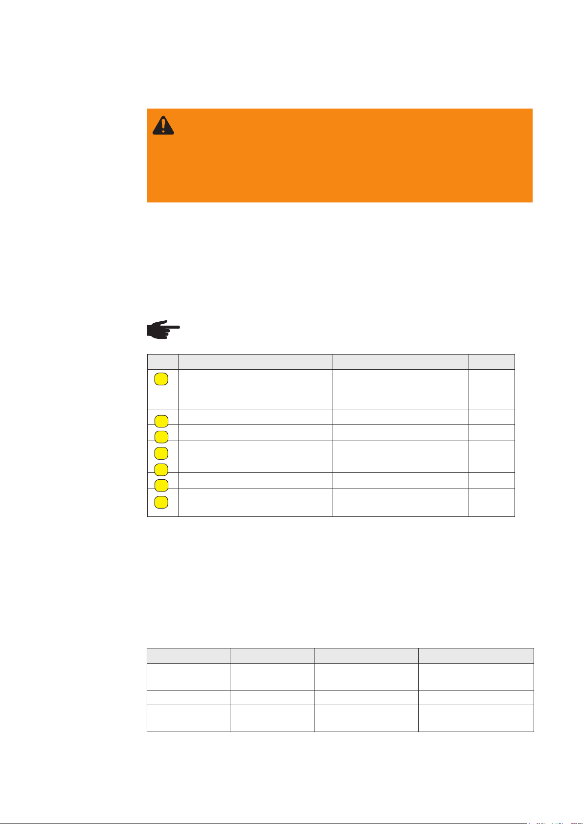
No. Function
(1) Emergency Stop button
Stops all movements. The arc is
broken immediately.
(2) Start-up delay potentiometer
To set the time between igniting the
arc and starting the carriage.
(8)
(7)
(3)
(4)
(3) "Move manually" button
For manual ne positioning of the
carriage.
(4) "STOP" button
To stop the program sequence.
Combined with the "START" button,
used to determine the direction of
(5)(6)
FRC-9 remote control
rotation.
No. Function
(5) Preselect welding direction
To select the welding direction (direction of travel).
(6) START button
To start the welding process.
(7) Welding ON/OFF
Select program sequence with or without welding.
(8) Pneumatic ON/OFF
To control a pneumatic unit (e.g. lowering of torch).
(9) Welding speed potentiometer
To set the welding speed. This can also be changed during the welding process.
(10) Digital display of welding speed
Displays the carriage speed in [cm/min].
NOTE! Detailed information about using the remote control and setting
the desired welding parameters, plus information about maintenance and
troubleshooting, can be found in the FRC-9 operating instructions.
7

Welding positions
Possible
welding positions
Exceptional track consistency is assured by the wheels with grooves and the 2-wheel
drive, which can be uncoupled.
The following welding positions are possible:
- PA position
Preparing the carriage
Checking the
surface of the
workpiece and
the carriage to
ensure they are
clean
Carriage strain
relief
Before positioning the carriage, check the following:
- The surface of the workpiece must be clean (no sand, shavings, etc.)
- The tread and grooves of the drive wheels must not be damaged and must be free of
shavings, dirt and welding spatter
To attain optimum wirefeed, observe the following when connecting and routing the
hosepack:
- Do not allow the hosepack to become kinked
- Always lay the hosepack as straight as possible
- Suspend hosepack if necessary. Use balancer and hosepack holder.
Hosepack handling
8

Commissioning
Checking the
connections
WARNING! Operating the equipment incorrectly can cause serious injury and
damage. Do not use the functions described here until you have thoroughly
read and understood the following documents:
- These operating instructions
- all the operating instructions for the system components,
especially the safety rules
The following activities and work steps apply to the installed system. All connections
must be established. Before start-up, check the connections of the following system
components:
- Power source
- Cooling circuit
- Gas cylinder
- Wire-feed unit
- Welding torch with hosepack
- Workpiece
Precise information on the assembly and connection of the system components can be
found in the relevant system component operating instructions.
Switching on
system
components
Dening
parameters for
the carriage
IMPORTANT! There are no xed rules for the sequence in which the system
components are switched on. They can be switched on in any order.
On the following system components turn the main switch to the "ON - 1" position:
- Carriage control unit
- Power source
- Wire-feed unit (if power is not supplied from the power source)
Determine the following settings for the welding process:
- Start-up delay
- Welding direction
- Traversing speed
9

Carrying out
test run
welding process
Perform a test run to check that all system components work together correctly. This is
done without an arc and thus allows you to check all movements during the process.
1. Switch the "Welding ON / OFF" toggle switch to the OFF position.
2. Press the START button. The welding test sequence starts.
IMPORTANT! Never leave the machine unattended, particularly when it is moving
automatically.
3. Carry out a visual check during the process.
4. If necessary, make the relevant corrections (welding torch position, direction of travel
of carriage, traversing speed, etc.).
5. After the test, move the carriage back to its original position.
Start the welding process:Starting the
1. Switch the "Welding ON / OFF" toggle switch to the ON position.
2. Press the START button. The welding process starts.
IMPORTANT! Never leave the machine unattended, particularly when it is moving
automatically.
10

Troubleshooting
General
Basic
requirements for
the system to
work
Carriage
In the event of faults, note that the functioning of the entire system depends on many
additional components (power source, wire-feed unit, etc.) that are also potential sources
of problems.
- Connections established between separate system components
- System components are supplied with electricity and the mains voltage is as
specied (see rating plate)
Carriage is switched on but does not move
Cause: Carriage overloaded (e.g. the torch cables pull the carriage up)
Remedy: Relieve cable strain (suspend)
Cause: Wheels dirty (with oil)
Remedy: Clean the wheels
Play on the torch
Cause: Play on the handles
Remedy: Tighten handles
Control,
remote control
Cause: Play on the guide rails
Remedy: Tighten the pressure screws
Nothing happens, main switch does not light up
Cause: Main switch is switched o
Remedy: Switch the device on
Cause: No connection to the mains
Remedy: Check the mains lead, mains plug and mains cable
Cause: Mains fuse is faulty
Remedy: Replace the mains fuse: glass-tube fuse
No function, main switch lights up
Cause: Emergency Stop has been actuated
Remedy: Release the Emergency Stop button
Cause: No connection to the carriage
Remedy: Check the control line
Cause: Frequency converter error
Remedy: - Switch the device o
- Wait 15 seconds
- Switch the device on again
11

Control,
remote control
(continued)
Carriage does not move after start-up or when in inching mode
Cause: Emergency Stop has been actuated
Remedy: Release the Emergency Stop button
Cause: Frequency converter error
Remedy: - Switch the device o
- Wait 15 seconds
- Switch the device on again
Arc ignites, carriage does not move
Cause: Value too high for start-up delay
Remedy: Change the "Start-up delay time" parameter (start-up delay
potentiometer)
Carriage moves but arc does not ignite
Cause: Power source switched o
Remedy: Switch on the power source
Cause: Welding ON / OFF selector switch set to the OFF position
Remedy: Set the selector switch to ON
12
Maintenance and care
Personnel
Maintenance
record
Maintenance
operations and
intervals
WARNING! Risk of injury and damage from incorrectly performed
maintenance.
All maintenance work on the FDV 50 carriage must only be carried out by
trained technicians. It is essential to adhere
to the maintenance intervals and maintenance procedures. The manufacturer
accepts no liability for any damage caused by inadequate or poorly performed
maintenance.
The operator must put the following organisational measures in place with regard to
maintenance:
- keeping a service book with the most important data (date, operator, maintenance
activities carried out)
NOTE! Before beginning maintenance work, switch o device and disconnect
from mains supply.
Item Part Action Interval
Linear guides Clean, check oil lm, elimi-
A
nate play: tighten pressure
screws with Allen key
Thread play Clean, regrease M
B
Rack and pinion Clean, regrease M
C
Rollers and rails Clean, check position M
D
Ventilation openings Clean W
E
Terminal contacts Clean W
F
Wheels, underbody, guide
G
wheels, guide rails
Clean D
M
Recommended
lubricants
D Daily
W Weekly
M Monthly
1/2 y Half-yearly
Y Yearly
IMPORTANT! Lubricants with solid lubricant additives (e.g.: MoS2, graphite and PTFE)
are not suitable for guiding systems.
Lubricant DIN DIN number Comment
Lubricating
grease
Lubricating oil CLP32-100 51517 Part 3 ISO VG 32-100
Conductive
paste
KP 2-K 51502 / 51825 Lithium soap-based
grease
-- -- Item no. 48,0009,0157
13

Carriage
components
F
G
F
G
G
G
G
G
C
G
14

Technical data
FDV 50
carriage
FDV 50
dimensions
Mains voltage/frequency 230 V / 50-60 HZ
Control voltage 24 V DC
Power consumption 180 VA
Max. load 50 kg
Track width 370 mm
Welding position PA
Horizontal speed (load = 50 N) 0-199 cm/min
Net weight (without remote control and weld tracking) 41 kg
H
C
E
G
A 792 mm
B 437 mm
C 345 mm
D 592 mm
D
AB
F
E 370 mm
F 1069 mm
G max. 379.5 mm
H 678 mm
15

Options and accessories
F
C
U
9
/
M
1
FDV 50
TUCHEL
FRC-9
System overview
1
Pneumatic cylinder
FPT 100 8,045,228
or
FPT 150 8,045,227
38,0100,008 1
24V + DC
Installation kit
Start/Stop second power source I-kit
Item number: 8,100,107
Including 3 m Tuchel connecting cable
TUCHEL
38,0100,0018
Power source
A
Installation kits FTV 20 / FTV 50:
1
I-Kit Start-Stop Power source 2:
8,100,107
Power source
B
LEGEND:
--------- Option
______ Standard
(included in delivery)
Connecting
cable
5 m connecting cable to FTP (pneum. torch positioning)
Item number: 38,0100,0081
16

/ Battery Charging Systems / Welding Technology / Solar Electronics
FDV-50
Spare parts list,
circuit diagram
EN
Carriage
17

18
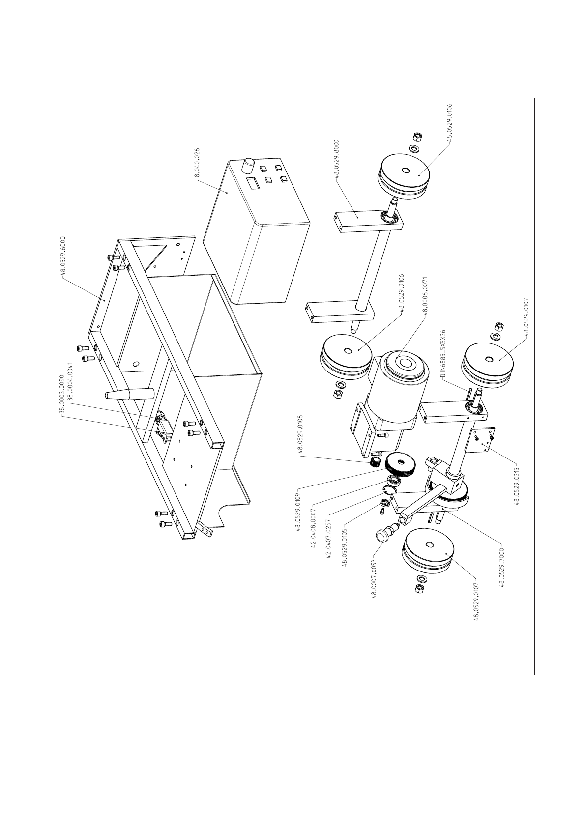
48,0529,0000 FDV 50 carriage
19

48,0529,0000 FDV 50 carriage
Designation: Item number:
Thrust washer 48,0529,0105
Impeller 48,0529,0106
Impeller drive 48,0529,0107
Drive pinion 48,0529,0108
Intermediate cog 48,0529,0109
Limit switch plate 48,0529,0315
Base frame, complete 48,0529,6000
Drive axis, complete 48,0529,7000
Front axis, complete 48,0529,8000
Base housing 38,0003,0090
Cable gland 38,0004,0041
Spur gear motor 48,0006,0071
Stop bolt without locking nut, with button 48,0007,0053
FCU-9M1 8,040,026
Locking ring 42,0407,0257
Bearing 42,0408,0007
Spring DIN6885_5x5x36
FRC-9 remote control 8,046,016
48-0385-C000 I-kit Limit switch
Designation: Item number:
Limit switch 90° 38,0002,0166
Cable connection 38,0004,0090
20

8,040,026 FCU-9M1
38,0102,0017
38,0006,0043
43,0001,1397
43,0001,1115
38,0006,0087
38,0102,0031
4,085,0144
43,0003,0002
43,0003,0001
43,0003,0148
38,0003,0089
43,0003,0235
43,0004,3206
38,0003,0089
Item no. Name
4,085,144 MP-Print
38,0006,0087 Mains switch
38,0102,0017 Frequency converter
38,0102,0031 PLC
38,0006,0043 Relay 24VDC 1Wl
43,0001,1115 Line lter
43,0001,1397 24 VDC mains adapter
43,0004,3206 5 m mains cable
43,0003,0001 Handle cap
43,0003,0002 Plug connector
43,0003,0148 Plug insert
38,0003,0089 Connector housing
43,0003,0235 Plug insert
21
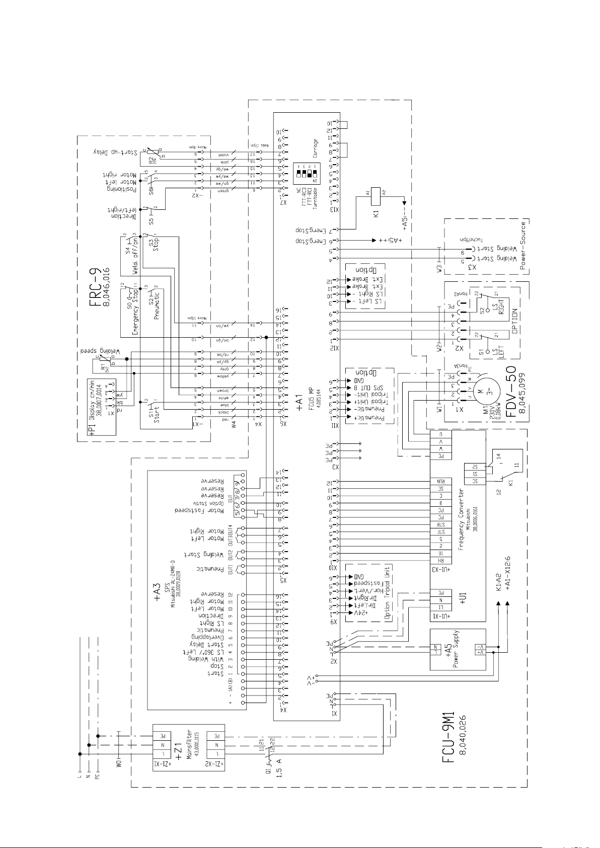
Wiring diagram
with one Powersource
22
24VDC 0,4A
43,0001,1397

with two Powersources
23
24VDC 0,4A
43,0001,1397

24
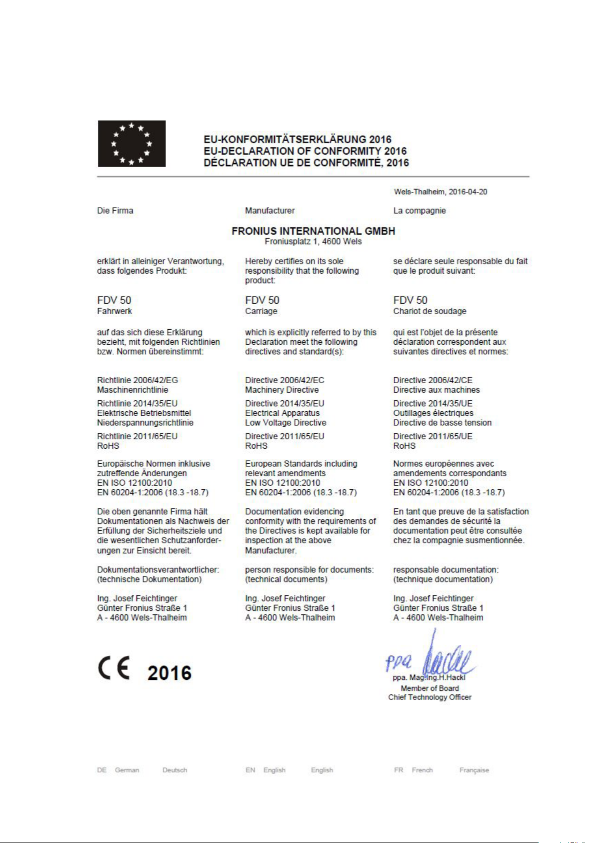
EU-Declaration of conformity
25

FRONIUS INTERNATIONAL GMBH
TechSupport Automation
www.fronius.com
www.fronius.com/addresses
26
 Loading...