

Page 1

/ Perfect Welding / Solar Energy / Perfect Charging
FDV 22 MF
Operating Instructions
EN
Carriage
42,0410,1645 V09 - 03082016
Page 2

Page 3

Contents
General ............................................................................................................................................................ 3
Principle......................................................................................................................................................3
Machine concept ........................................................................................................................................ 3
Field of application ..................................................................................................................................... 3
Proper use .................................................................................................................................................. 3
Improper use .............................................................................................................................................. 4
Conversions or modications ..................................................................................................................... 4
Operating instructions ................................................................................................................................ 4
Instructions ................................................................................................................................................. 4
Warning notices on the driving vehicle ....................................................................................................... 5
Scope of supply .......................................................................................................................................... 6
Options ....................................................................................................................................................... 7
Driving vehicle components .......................................................................................................................... 10
Conguration FDV 22 MF with oscillation unit ........................................................................................ 10
Conguration FDV 22 MF without oscillation unit ................................................................................... 10
Controls, connections and add-ons ............................................................................................................... 11
Driving vehicle control panel .................................................................................................................... 11
“Con” display ............................................................................................................................................ 12
“InF” display..............................................................................................................................................12
Total path active display ........................................................................................................................... 12
Display during program sequence ........................................................................................................... 12
“Bat” display ............................................................................................................................................. 12
“End“ display ............................................................................................................................................ 12
Control panel oscillation unit option ......................................................................................................... 13
Charger and battery pack ......................................................................................................................... 14
AC-ACvoltage transformer ....................................................................................................................... 15
Welding position and seam tracking ..............................................................................................................16
Possible welding positions ....................................................................................................................... 16
Guidance of the carriage .......................................................................................................................... 17
Second torch holder ................................................................................................................................. 20
Preparing the driving vehicle ......................................................................................................................... 21
Fitting the handle ...................................................................................................................................... 21
Fitting the guide rails ................................................................................................................................ 21
Fitting the brushes (option) ...................................................................................................................... 22
Fitting lateral guides (Option) ................................................................................................................... 23
Fitting lateral guides with exible rail (Option) .......................................................................................... 24
Fitting the additional torch holder (Option) ............................................................................................... 25
Connecting the charger to the mains supply ............................................................................................ 26
Charge the battery pack ........................................................................................................................... 26
Insert battery pack in driving vehicle docking station ............................................................................... 27
Adjusting the guide wheels ...................................................................................................................... 28
Check the surface of the workpiece and the driving vehicle to ensure they are clean ............................. 28
Position the driving vehicle and activate the permanent magnet ............................................................. 28
Attach fall protection (vertical operation) .................................................................................................. 29
Mounting and adjusting the welding torch ................................................................................................ 29
Driving vehicle strain relief ....................................................................................................................... 30
1
Page 4

Start-up .......................................................................................................................................................... 31
Check the connections ............................................................................................................................. 31
Switch on system components ................................................................................................................. 31
Dene driving vehicle parameters ............................................................................................................ 31
Loading a welding program ...................................................................................................................... 32
Carry out test run......................................................................................................................................32
Start the welding process ......................................................................................................................... 32
Setting the driving vehicle parameters .......................................................................................................... 33
Continuous welding .................................................................................................................................. 33
Interval welding ........................................................................................................................................ 35
Path welding ............................................................................................................................................. 38
Oscillation option ........................................................................................................................................... 40
Setting the oscillation ............................................................................................................................... 40
Troubleshooting ............................................................................................................................................. 41
General.....................................................................................................................................................41
Basic requirements for the system to work .............................................................................................. 41
Displayed error messages ....................................................................................................................... 41
Driving vehicle .......................................................................................................................................... 41
Oscillation ................................................................................................................................................. 42
Maintenance and care ................................................................................................................................... 43
Personnel ................................................................................................................................................. 43
Maintenance record ................................................................................................................................. 43
Maintenance operations and intervals ..................................................................................................... 43
Recommended lubricants ........................................................................................................................ 43
Horizontal torch adjustment unit ............................................................................................................... 44
Vertical torch adjustment unit ................................................................................................................... 44
Driving vehicle front end ........................................................................................................................... 44
Driving vehicle rear end ........................................................................................................................... 44
Driving vehicle drive unit .......................................................................................................................... 45
Charger .................................................................................................................................................... 45
Battery pack ............................................................................................................................................. 45
Disposal of components ........................................................................................................................... 46
Technical data ...............................................................................................................................................47
Driving vehicle FDV 22 MF....................................................................................................................... 47
FDV MF charger + battery pack ............................................................................................................... 47
AC-AC voltage transformer ...................................................................................................................... 47
Oscillation unit FOU 30 / ML6 .................................................................................................................. 48
Dimensions FDV 22 MF without oscillation unit ...................................................................................... 48
Dimensions FDV 22 MF with oscillation unit ........................................................................................... 49
Spare parts ...................................................................................................................................................... 1
Circuit diagram ................................................................................................................................................ 6
EU-Declaration of conformity .......................................................................................................................... 7
2
Page 5
General
Principle
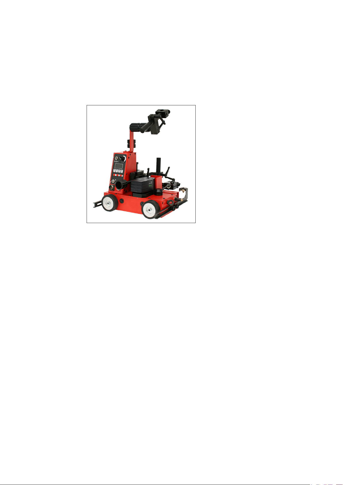
Machine concept
Driving vehicle FDV 22 MF is a portable, battery-powered longitudinal truck with 4-wheel
drive. The driving vehicle is used to execute mechanised butt and llet welds in horizontal or vertical welding positions, with or without oscillation.
Driving vehicle FDV 22 MF has been for
designed for exibility and to improve productivity in the execution of longitudinal
weld seams. A spatter guard mounted on
the working side and powder coating of all
housing components enable use in harsh
operating conditions.
A large holding and carrying handle and
robust yet lightweight design allow quick
and easy positioning on the workpiece.
The driving vehicle adheres to the component by means of a permanent magnet.
This guarantees the best possible traction
even in vertical use.
The guide wheels automatically track the
torch in the lled joint.
The universal torch holder allows use of
Driving vehicle FDV 22 MF
both manual and machine welding torches.
Field of application
Proper use
The FDV 22 MF can be equipped with a torch oscillation unit.
The driving vehicle together with the optional oscillation unit is powered by the inter-
changeable battery pack.
The control unit is integrated into the driving vehicle. The control panel has an illuminated
display allowing simple and user-friendly parameter setting for the driving vehicle.
Driving vehicle FDV 22 MF can be used in all situations where a high degree of exibility
is required when executing longitudinal weld seams:
- Welding of longitudinal members
- Shipyards
- Bridge construction
- Workshops
- Production halls
- Building sites
Driving vehicle FDV 22 MF must only be used for performing mechanised butt and llet
welds in horizontal or vertical welding positions. Any other use shall be deemed to be improper use and the manufacturer will assume no responsibility for any damages arising.
The following welding processes are possible:
- MIG/MAG process
Proper use also includes:
- use of the charger FDV MF and battery pack (14.4V / 3 Ah) included with the driving
vehicle
- use of the permanent magnet with a minimum sheet thickness of 5 mm
- use of MIG / MAG welding torches with a holder diameter of 16 - 22 mm
3
Page 6

Proper use
(continued)
- use with the „Drive wheel stainless steel“ option in PA welding position
- carrying out all maintenance work at the appropriate intervals
- keeping a service book with the most IMPORTANT data (date, operator, activities
carried out)
- using the spare parts stipulated by Fronius
- following all the information in the operating instructions
- using this document in conjunction with the operating
instructions of the integrated system components (power source, wire-feed unit, etc.)
Improper use
Conversions or
modications
Operating
instructions
Any use of the machine other than for its intended purpose shall be deemed improper
use. This includes:
- using on preheated workpieces > 50 ° C
- Transporting people
- Standing on the machine or using it as a work platform
- As a storage surface for tools
- Use outside the permitted technical operating limits
- Use in hazardous areas
If the user carries out any unauthorised conversion or modication of the equipment, any
liability or warranty from the manufacturer is invalidated.
The electromagnetic characteristics of the equipment can be adversely aected by any
kind of addition or modication. No modications or upgrades to the equipment should
therefore be undertaken without rst consulting the manufacturers and receiving written
approval.
The operating instructions help you to use the carriage eciently and must be accessible
at all times.
- Keep the operating instructions near the corresponding parts of the carriage at all
times.
- Clearly mark the place where the instructions are kept
- Ensure that all persons using the carriage know where the operating instructions are
located.
- The operating instructions will only be able to help you if you can get to them when
there is a problem!
IMPORTANT! The manufacturer shall not be liable for any damage that arises from failure to observe the operating instructions.
Instructions The system operator must, before they start, tell all people working on the carriage
about:
- the theoretical and practical aspects of operating the system
- the safety regulations applicable to the system.
IMPORTANT! This obligation applies in particular to persons who only work occasionally
on the carriage.
4
Page 7
Warning notices
Type:
Ser.No.:
Art.No.:
A-4600 Wels
www.fronius.com
U weight max. load
14,4 VDC 15 kg 22 kg
2009
FDV 22/MF
8,045,368
20 25 9503
on the driving
vehicle
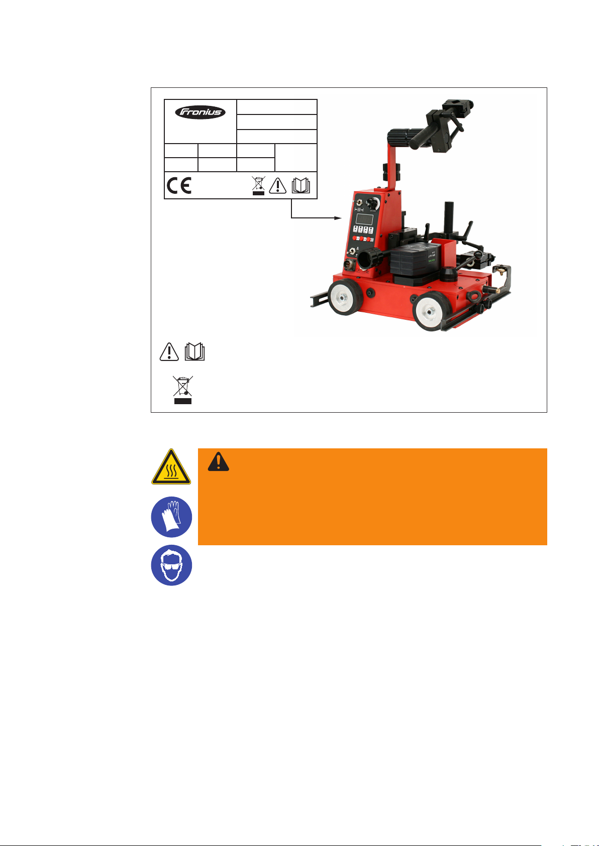
A number of safety symbols can be seen on the rating plate axed to the driving vehicle.
The safety symbols must NOT be removed or painted over.
Do not use the functions until you have fully read all the operating instructions.
Do not dispose of used chargers with domestic waste. Dispose of them according to
safety rules.
Rating plate FDV 22 MF
WARNING!
Risk of burns from hot surfaces.
The protective plate covering the battery pack heats up over
extended periods of welding. Touching the plate may cause burns.
- Do not touch the protective plate.
- Wear protective gloves and suitable safety goggles or a protective helmet.
5
Page 8
Scope of supply
(1)(8) (2)
(3)
(4)(6) (5)(7)
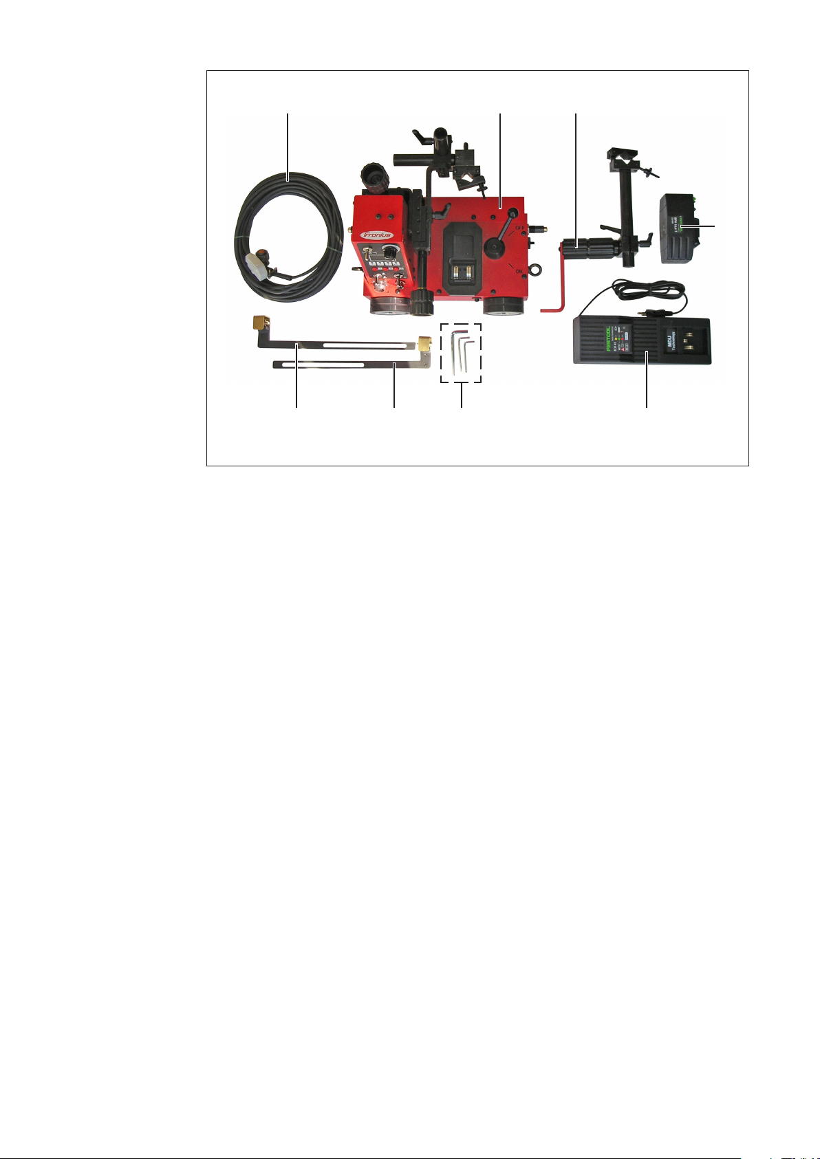
FDV 22 MF scope of supply
(1) Driving vehicle FDV-22MF
(2) Handle with hose pack holder
(3) Battery pack 14.4 V / 3 Ah
(4) Charger FDV MF
(5) Allen keys 2.5 / 3 / 4
(6) Front guide rail
(7) Rear guide rail
(8) Connecting cable to power source
6
Page 9
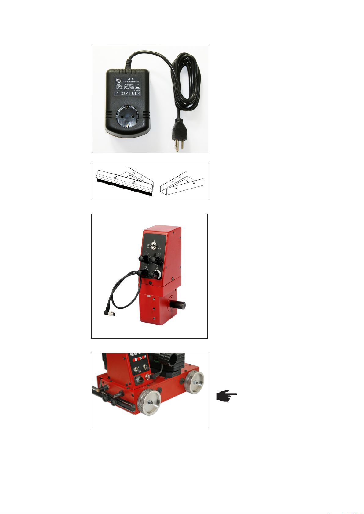
Options The optional equipment of the driving vehicle comprises:
- AC-AC voltage transformer
(38,0006,0164)
- Driving vehicle brush (48,0005,1425)
This accessory comprises two parts.
Brush bracket and 1x brush.
- Oscillation unit FOU 30 / ML6
(8,045,370)
For workpieces with very rough surface:
- Stainless steel drive wheel
(48,0005,1603), article number includes 1 pc. stainless steel wheel.
IMPORTANT! Using the „Stainless steel drive wheel“ option
is permitted only in PA welding
position.
7
Page 10
Options
(continued)
- Additional torch holder for second
torch (48,0005,1893)
Lateral guides:
(1) Lateral guide, tiltable
(48,0005,1890)
1
(2) Lateral guide for edge
(48,0005,1888)
2
(3) Lateral guide, magnetic
(48,0005,1892)
3
8
Page 11

Options
(continued)
5
4
Lateral guide with guiding rail:
(4) Guide arm for exible rail, 1850 mm (2 Stück)
(48,0005,1897)
(5) Flexible guiding rail, 1850 mm
(48,0005,1894)
(6) Magnetic block for guiding rail
(48,0005,1895)
IMPORTANT! 10 magnetic blocks per rail are neccessary!
6
9
Page 12

Driving vehicle components
Conguration
FDV 22 MF with
oscillation unit
Handle
Hosepack holder
On-board
control unit
Horizontal torch
adjustment unit
Battery pack
(14.4V / 3Ah)
Truck
with 4-wheel drive
Driving vehicle FDV 22 MF with oscillation unit FOU 30 / ML6
Lifting eye for securing the
driving vehicle
Vertical torch
adjustment unit
Limit switch
Oscillation unit
FOU 30 / ML6
Control lever for
permanent magnet
Universal torch holder
Guide wheels
Conguration
FDV 22 MF without oscillation
unit
Handle
On-board control unit
Horizontal torch
adjustment unit
Truck
with 4-wheel drive
Battery pack (14.4V / 3Ah)
Driving vehicle FDV 22 MF without oscillation unit
Vertical torch
adjustment unit
Lifting eye for securing
the driving vehicle
Hosepack holder
Control lever for
permanent magnet
Universal torch
holder
Guide wheels
Limit switch
10
Page 13

Controls, connections and add-ons
Driving vehicle
control panel
(10)
WARNING! Operating the equipment incorrectly can cause serious injury and
damage. Do not use the functions described until you have thoroughly read
and understood the following documents:
- these operating instructions
- all the operating instructions for the system components, especially the
safety rules
No. Function
(1) Traverse speed potentiometer
Used to adjust the traversing speed of
(1)
(2)
(3)
the driving vehicle.
Setting range: 5 - 150 cm/min
(2) Digital display
Shows the value of the currently se-
lected parameter. The digital display is
illuminated.
(3) Parameter selection display eld
The selected parameter is signalled
by the relevant LED lighting up. The
currently saved value appears in the
digital display.
Selectable parameters:
(9)
(8)
(7)
Driving vehicle FDV 22 MF control panel
(4) SELECT / ENTER button
- Press the button for 3 seconds to enable parameter entry
- To select the desired parameter (3)
- To accept the value set with the +/- buttons.
(5) Control unit ON/OFF toggle switch
For switching the driving vehicle control unit on and o.
(6) Connector for oscillation unit FOU30
For connecting the cable to the optional oscillation unit FOU 30.
(7) Connector for power source control
For connecting the cable to the power source.
(8) Welding ON/OFF toggle switch
For choosing whether to run the automatic program sequence with or without weld-
ing. Welding can be deactivated for test purposes.
(9) + / - button
For increasing or reducing the parameter value. Press the key for 2 seconds to
increase or reduce the parameter value quickly.
(4)
(5)
(6)
Welding segment [cm]
Setting range: 0.5 - 99.9 cm
Pause segment [cm]
Setting range: 0.5 - 99.9 cm
End-crater lling [s]
Setting range: 0.0 - 5 s
Back lling [s]
Setting range: 0.0 - 3 s
All 4 LEDs lit: Total path [cm]
Setting range: 1 - 999 cm
11
Page 14
Driving vehicle
control panel
(continued)
(10) Toggle switch Start LEFT / STOP / Start RIGHT
For starting and stopping the automatic program sequence.
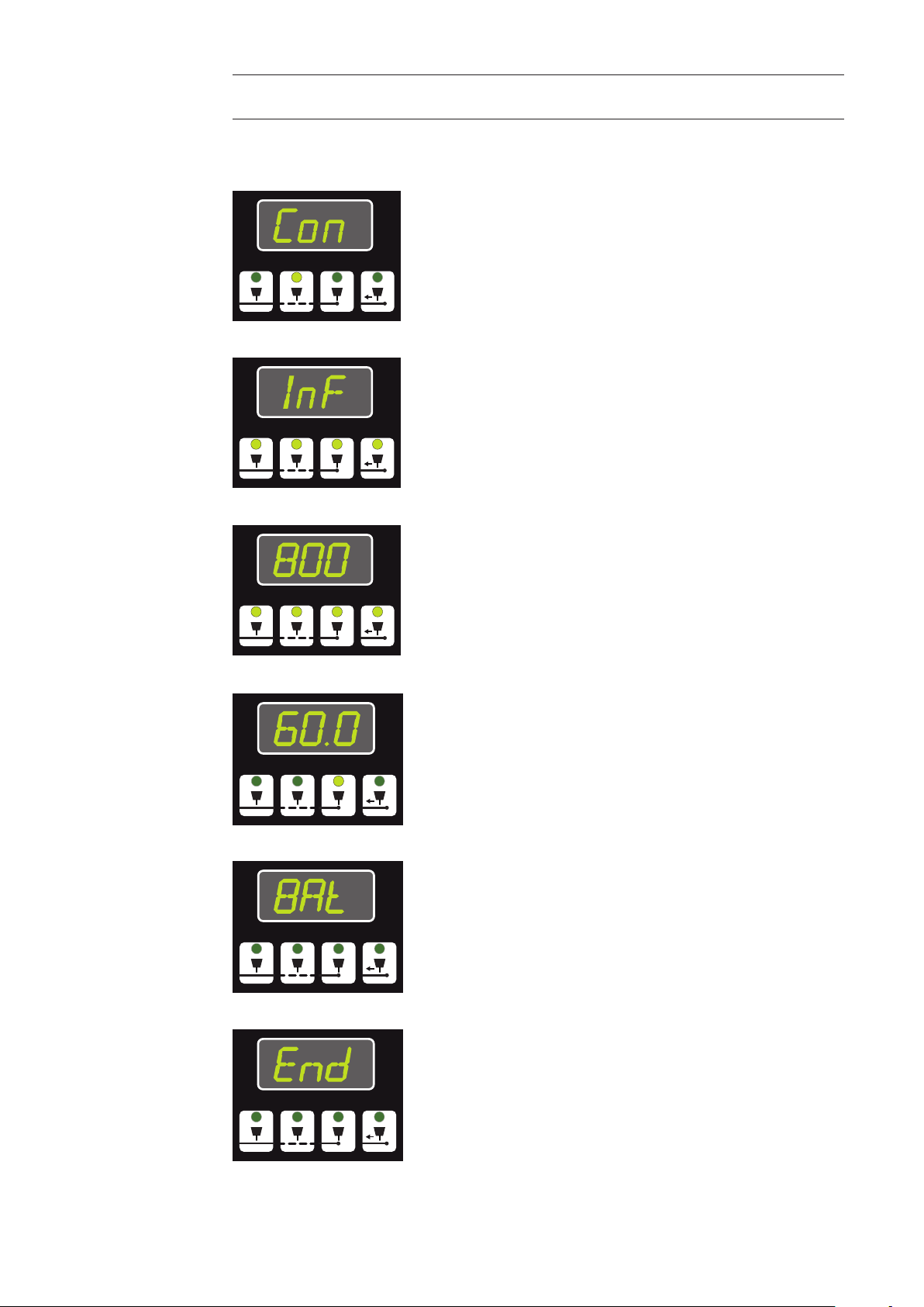
“Con” display
Con ... Constant. The pause segment is deactivated. The
display appears after the value "99.9" and before "0.5".
“InF” display InF ... Innite. The driving vehicle travels endlessly. The dis-
play appears after the value "999" and before "1".
Total path active
display
The driving vehicle travels the dened distance.
Setting range 1 - 999 cm.
Display during
program sequence
“Bat” display
“End“ display
"Traversing speed" display. Display range 5 - 150 cm /min.
The current step is signalled by the relevant LED lighting up.
Display ashes. The battery pack is nearly at. The battery
pack must be removed from the driving vehicle and recharged.
Program 'End' indication. All parameters have been completed.
A new automatic program sequence may be started using
the "Start LEFT / STOP / Start RIGHT" button (10).
12
Page 15
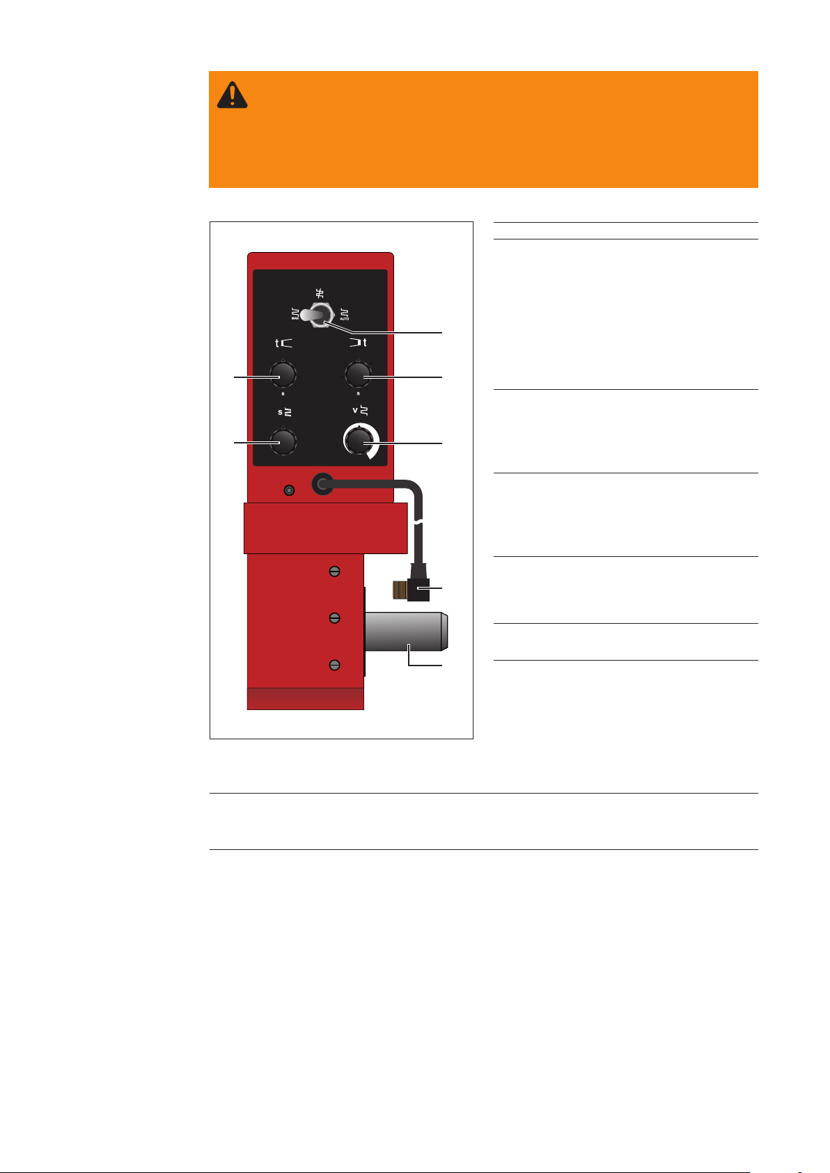
Control panel
oscillation
unit option
WARNING! Operating the equipment incorrectly can cause serious injury and
damage. Do not use the functions described until you have thoroughly read
and understood the following documents:
- these operating instructions
- all the operating instructions for the system components,
especially the safety rules
(7)
(6)
Oscillation unit FOU 30 / ML6 control panel
(1)
(2)
(3)
(4)
(5)
No. Function
(1) Oscillation mode toggle switch
MANUAL / OFF / AUTOMATIC
For selecting the oscillation mode of
the FOU 30.
MANUAL: Oscillation active immediately
OFF: Oscillation is deactivated
AUTOMATIC: Oscillation starts simultaneously with program sequence.
(2) Right dwell time potentiometer
For setting the dwell time of the torch
in the right reversal
position.
Setting range: 0 - 3 seconds
(3) Oscillation speed potentiometer
For setting the traversing speed of
the oscillation unit in mm / min. The
oscillation speed can only be adjusted
while the oscillation unit is running.
(4) Connection cable with male socket
For connection to the "Connector for
oscillation unit FOU30" of the driving
vehicle control panel.
(5) Support arm
For fastening the torch holder.
(6) Oscillation path potentiometer
To increase or reduce the oscillation
path (oscillation width).
The oscillation path can only be adjust-
ed while the oscillation unit is running.
Setting range: 1 - 30 mm
(7) Left dwell time potentiometer
For setting the dwell time of the torch in the left reversal position.
Setting range: 0 - 3 seconds
13
Page 16

Charger and bat-
i C
d
+
tery pack
WARNING! Operating the equipment incorrectly can cause serious injury and
damage. Do not use the functions described until you have thoroughly read
and understood the following documents:
- these operating instructions
- all the operating instructions for the system components, especially the
safety rules
CAUTION! The charger may be damaged if the wrong supply voltage
is used.
The FDV MF charger is designed for a supply voltage of 230 V. Directly connecting the charger to a 110 / 120 V mains supply can cause serious material
damage.
- Ensure that the charger is always operated using the correct supply voltage.
- Always use the AC-AC voltage transformer when operating the charger
on a 110/120 V mains supply.
(7)
(6)
(5)
Overview of charging set
No. Function
(1) Signal lamp YELLOW
Permanently lit: Charger is ready for use
(2) Signal lamp GREEN
Flashing: Battery pack is charging
Permanently lit: Battery pack is charged, under conservation charge
(3) Signal lamp RED
Flashing - general error warning: incomplete contact,
short-circuit, battery pack faulty;
Permanently lit: battery temperature outside permitted limits (5° - 45° C)
(4) Mains cable
For connection to the mains supply (230 - 240V).
(5) Charger docking station lower recess
For inserting the battery pack.
(6) Charger docking station upper recess
For locking the battery pack.
(7) Battery release button
For releasing the battery pack.
(1)
(2)
(3)
(4)
14
Page 17

AC-ACvoltage
transformer
WARNING! Operating the equipment incorrectly can cause serious injury and
damage. Do not use the functions described until you have thoroughly read
and understood the following documents:
- these operating instructions
- all the operating instructions for the system components, especially the
safety rules
The voltage transformer allows the charger to be operated using 110 V and 120 V mains
supplies. A transformed voltage of 230 V is provided at the output of the AC-AC voltage
transformer for the FDV MF charger (4).
No. Function
(1) 110 / 120 V AC mains plug
For connection to the 110 / 120 V
AC mains supply.
(2) 230 V AC output
For connection to the FDV MF
charger.
(1)
(2)
AC-AC voltage transformer
15
Page 18
Welding position and seam tracking
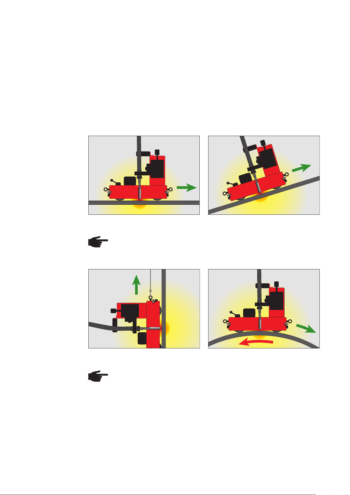
Possible
welding
positions
The 4-wheel drive and built-in permanent magnet ensure that the driving vehicle adheres
optimally to the workpiece and guarantee the best possible traction. The following weld-
ing positions are possible.
IMPORTANT! In vertical operation, the driving vehicle must be secured by a load secur-
ing device with a locking function to prevent it from falling. The load securing device must
be designed for the total weight of the vehicle. The manufacturer accepts no liability for
any damage to persons or property resulting from vertical use of the driving vehicle with-
out a load securing device.
SlopingHorizontal
NOTE! From an angle of 45° upwards, the driving vehicle must be secured by a
load securing device with a locking function to prevent it from falling.
Outside of container with min. diameter of 3000 mmVertical
NOTE! When used on the outside of a container, the container must be turned
in the opposite direction and at the same speed.
16
Page 19

Possible
welding
positions
(continued)
Inside of container with minimum diameter of 2500 mm
NOTE! When used inside a container, the container must be turned in the opposite direction and at the same speed.
Guidance of the
carriage
IMPORTANT! Use of the driving vehicle in the "PE" overhead position is prohibited.
The guide wheels automatically track the torch in the lled joint. They can be positioned
on either side of the driving vehicle. For detailed information about the correct setting of
the guide wheels, see the section "Preparing the driving vehicle". The guide wheels can
be set to the following positions:
Guidance on outside vertical surfaceGuidance on inside vertical surface
17
Page 20

Guidance of the
carriage
(continued)
Guidance on outside vertical surfaceGuidance on angle piece (vertical) or rail
Outside of curve with minimum diameter of 5000 mm Inside of curve with minimum diameter of
5000 mm
NOTE! When guided on a hori-
zontal angle piece, the welding
torch must only be placed on the
upper side.
Guidance on angle piece (horizontal) or rail
18
Page 21

Guidance of the
carriage with
optional lateral
guides
Lateral guide, tiltable
Lateral guide for edge
Standard lateral guide / with magnet
19
Page 22

Guidance of the
carriage with
optional lateral
guides
(continued)
Second torch
holder
Lateral guide with guiding rail
- Lateral guide for exible rail (2 pc.) (1850 mm / 72.84 in)
- Magnet block for guiding rail
- Guide arm for exible rail (1850 mm /72.84 in)
IMPORTANT! 10 magnetic blocks per rail are necessary!
IMPORTANT! Working with two welding torches is only possible in horizontal position!
20
Page 23

Preparing the driving vehicle
Fitting the handle
Fitting
the guide rails
1. Use two M5 x 16 screws to secure the
handle to the control panel housing.
2. Tighten the screws using a size 5 allen
key.
FDV-22 MF handle
FDV-22 MF driving vehicle
1. Use the M6 knurled screws to attach the guide rails to the driving vehicle.
2. Tighten knurled screws by hand rst. See "Setting the guide wheels" for information
on how to set the guide wheels.
21
Page 24

Fitting the brushes (option)
(a)
(a)
(b)
FDV-22 MF driving vehicle with brushes
NOTE! The brush may be tted to either the front or rear of the driving vehicle.
1. Remove the M6 knurled screws (a)
2. Attach the brush brackets as shown
3. Insert the M6 knurled screws (a) and tighten by hand.
4. Fit the brush to the front or rear brush bracket using M6 screws (b)
22
Page 25

Fitting lateral
guides
(Option)
All optinal lateral guides for the FDV 22 carriage are mounted with the M6 knurled
screws.
The lateral guides are mounted on the front sides of the carriage.
Lateral guide, tiltable
Lateral guide for edge
Lateral guide, magnetic
23
Page 26

Fitting lateral
guides with exible rail
(Option)
The lateral guides, which are used with guide rail, are xed with the M6 knurled screws.
The exible guide rail is xed with magnet blocks. 10 magnet blocks are necessary for
one rail (1850 mm / 72.84 in), to ensure a secure t.
The rails can be mounted on the magnetic blocks in the following way:
- by forming a butt joint
- by forming a lap joint
Mount the rails with the delivered M5x16 xing screws.
M5x16
Butt joint Lap joint
Holding force of one magnet block, placed on a 5mm (0.2“)
thick ferromagnetic surface:
- up to a temperature of 100°C (212 °F): 90 N
- above a temperature of 180°C (356°F): 54 N
24
Page 27

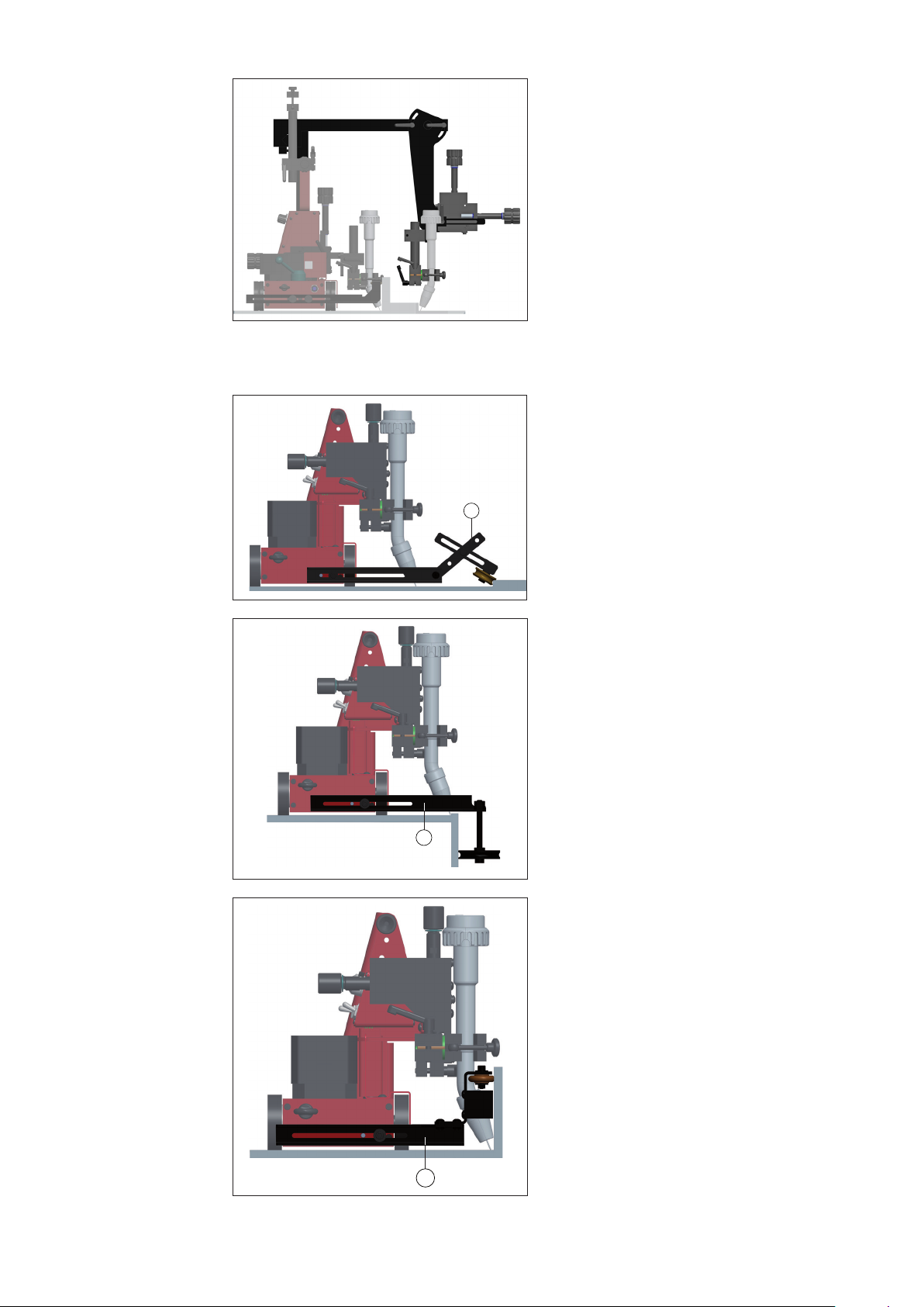
Fitting the additional torch holder
(Option)
The additional torch holder is mounted on the front side of the carriage, before the control panel.
1. Remove the right knurled screw and
the lifting eye.
2. Place the recress (a) of the totch
holder on the lateral guide.
3. Fix the torch holder with the deliver-
ed screws (b).
4. Tighten the knob (c).
(c)
(b)
(b)
(a)
5. Tighten the knurled screw and the
lifting eye into the two holes above
the xing screws.
25
Page 28

Connecting the
charger to the
mains supply
CAUTION! The charger may be damaged if the wrong supply voltage
is used.
The FDV MF charger is designed for a supply voltage of 230 V. Directly connecting the charger to a 110 / 120 V mains supply can cause serious material
damage.
- Ensure that the charger is always operated using the correct supply voltage.
- Always use the AC-AC voltage transformer when operating the charger
on a 110/120 V mains supply.
110 / 120 V mains supply:
1. Plug the AC-AC voltage transformer
(a) into the 110 / 120 V socket.
2. Plug the charger into the AC-AC vol-
tage transformer output (b).
The YELLOW signal lamp lights up.
(a)
Charge the
battery pack
(b)
AC-AC voltage transformer
230 V mains supply:
Plug the charger into the 230 V socket. The YELLOW signal lamp lights up.
IMPORTANT! The mains voltage and frequency must be as indicated on the rating plate.
1. Insert the battery pack with the ridge
in the lower recess (a) of the charger
docking station.
IMPORTANT! The charging time for
the battery pack is 45 minutes. If a
warm NiMH battery pack (> 37°C) is
used, charging takes place at a reduced charging current. In this case
the charging time for the battery pack
at 3.0 Ah is approx. 100 minutes.
(a)
Place battery pack in charger docking station
26
Page 29

Charge the
battery pack
(continued)
Lock the battery pack in place
(b)
(c)
2. Push the battery pack into the charger
docking station until it engages with
the retainer (b) in the upper recess.
The battery pack charges up. The
signal lamp ashes GREEN during the
charging process.
IMPORTANT! The battery pack is fully
charged after a charging time of 45
minutes. The GREEN signal lamp is
then lit permanently.
3. Once the battery has nished charging, press the battery release button
(c) and remove the battery pack from
the charger.
Insert battery
pack in driving
vehicle docking
station
(a)
Place battery pack in driving vehicle docking station
(d)
(b)
1. Insert the battery pack with the ridge
in the lower recess (a) of the driving
vehicle docking station.
2. Push the battery pack into the driving
vehicle docking station until it engages
with the retainer (b) in the upper recess.
3. To release, press the battery release
button (d) and remove the battery pack
from the driving vehicle.
Lock the battery pack in place
27
Page 30

Adjusting the
guide wheels
5 - 10 mm
(b)
(b)
(a)(a)
Direction of travel
Adjusting the guide wheels
1. Undo the fastening screws (a)
2. Extend the guide wheels (b) to the desired length. To ensure that the driving vehicle
keeps to the chosen direction, the extended guide wheels must be extended by at
least 5 - 10 mm (see diagram).
3. Tighten the fastening screws (a)
Check the surface of the workpiece and the
driving vehicle to
ensure they are
clean
Position
the driving vehicle and activate
the permanent
magnet
Before positioning the driving vehicle, check the following:
- The surface of the workpiece must be clean (no sand, swarf etc.)
- The bottom plate of the driving vehicle must be free of objects which can be attracted
by the magnet
- The rubber elements of the drive wheels must be undamaged and free of swarf
- The guide wheels must be clean, undamaged and free of welding spatter
WARNING! The activated permanent magnet poses a risk of injury
With the permanent magnet activated, there is a danger of injury to the ngers
when positioning the driving vehicle. The driving vehicle must only be positioned with the permanent magnet deactivated.
- Turn the control lever to the "OFF" position
- Only hold the driving vehicle by the handle and not by the bottom plate
1. Place the driving vehicle on the workpiece. Adjust the side guide wheels to
the workpiece.
2. If necessary, correct the position of the
guide wheels
3. Set the permanent magnet control
lever to the "ON" position
Activate the permanent magnet
28
Page 31

Attach fall
protection
(vertical operation)
IMPORTANT! In vertical operation, the driving vehicle must be secured by a load secur-
ing device with a locking function to prevent it from falling. The load securing device must
be designed for the total weight of the vehicle. The manufacturer accepts no liability for
any damage to persons or property resulting from vertical use of the driving vehicle with-
out a load securing device.
1. Attach the snap hook of the load
securing device to the securing ring of
the driving vehicle
NOTE! Do not stand beneath a
suspended driving vehicle.
Attach load securing device
2. Make sure the cable is kept permanently taut
Mounting and
adjusting the
welding torch
Check the cable
1. Undo the fastening screw (a) on the
torch holder
2. Insert the welding torch and tighten the
fastening screw (a)
(a)
Fitting the welding torch
29
Page 32

Mounting and
adjusting the
welding torch
(continued)
(c)
Setting up the welding torch
(d)
(a)
(b)
3. Adjust the torch angle:
- Undo the fastening screws (a)
- Turn the clamp block (b) and
set the desired angle
- Fix the locking lever (a)
4. Turn the adjusting wheel on the
relevant mechanical adjustment unit
(c), (d) until the correct welding torch
position is reached.
Driving vehicle
strain relief
To attain optimum wirefeed, observe the following when laying the hose pack:
- Do not allow the hose pack to become kinked
- Always lay the hose pack as straight as possible
- Suspend the hose pack (it must not come into contact with the oor), use balancers
and hose pack holders (e.g. Universal hose pack holder)
Hose pack handling
1. Undo the fastening screw (a) on the
clamp
2. Insert the hose pack as illustrated
IMPORTANT! Make sure the hose
(a)
pack does not become kinked - this
can lead to wire feed problems.
3. Tighten the fastening screw (a)
Fixing the hose pack
IMPORTANT! Please note the
maximum tension load on the
hosepack holder (see chapter
„Technical Data“). This must not
be exceeded.
30
Page 33

Start-up
Check the connections
Switch on
system components
WARNING! Operating the equipment incorrectly can cause serious injury and
damage. Do not use the functions described until you have thoroughly read
and understood the following documents:
- these operating instructions
- all the operating instructions for the system components, especially the
safety rules
The following activities and work steps apply to the installed system. All connections
must be established. Before start-up, check the connections of the following system components:
- Power source
- Cooling circuit
- Gas cylinder
- Wire-feed unit
- Welding torch with hosepack
Precise information on the assembly and connection of the system components can be
found in the relevant system component operating instructions.
WARNING! Danger of injury from premature arc ignition
The arc may be ignited accidentally. This can lead to serious eye injury.
Before switching on the system components, make sure that the "Start LEFT
/ STOP / Start RIGHT" toggle switch on the driving vehicle control panel is set
to the "STOP" position.
Dene driving
vehicle parameters
IMPORTANT! There are no xed rules for the sequence in which the system compo-
nents are switched on. They can be switched on in any order.
On the following system components turn the main switch to the "ON - 1" position:
- Driving vehicle control unit
- Power source
- Wire-feed unit (if power is not supplied from the power source)
Set the following welding process parameters on the driving vehicle:
- Traversing speed
- Welding segment
- Pause segment
- Crater-lling
- Back-lling
- Total path
- Oscillation parameters (mode, dwell times, oscillation speed, oscillation path)
- Position the contact cam (with continuous welding)
For detailed information about entering the driving vehicle parameters, see the section
"Setting the driving vehicle parameters".
31
Page 34

Loading a welding program
IMPORTANT! For each workpiece a corresponding welding program must be created.
This contains a list of welding parameters that is saved under a specic program number
(job number). These programs can be reloaded at any time, and corrected as required.
The programs are managed from the power source control panel. When an analogue
power source is used, the requisite welding parameters must be set manually on the
power source.
Load the relevant welding program on the control panel for the power source. More detailed information on managing welding programs can be found in the operating instructions for the power source.
Carry out test run
Perform a test run to check that all system components work together correctly. This is
done without an arc and thus allows you to check all movements during the process:
NOTE! When the vehicle is in use, the permanent magnet lever must be set to
“ON”. Check this before starting work.
1. Turn the Welding ON/OFF toggle switch to the "OFF" position
2. Set the "Start LEFT / STOP / Start RIGHT" toggle switch to the de-
sired direction - The test run starts. To stop the process early, turn the
switch to the "STOP" (0) position.
IMPORTANT! Never leave the machine unattended, particularly when
it is moving automatically.
3. Carry out a visual check during the test run
4. Make any necessary corrections (welding torch position, direction of
travel, traversing speed, oscillation motion, etc.)
process
Start the welding process:Start the welding
1. Turn the Welding ON/OFF toggle switch to the "ON" position
2. Set the "Start LEFT / STOP / Start RIGHT" toggle switch to the desired
direction - the welding process starts. To stop the process early, turn
the switch to the "STOP" (0) position.
IMPORTANT! Never leave the machine unattended, particularly when
it is moving automatically.
IMPORTANT! If no traversing path has been dened, the welding process stops automatically once the relevant limit switch is actuated.
32
Page 35

Setting the driving vehicle parameters
Continuous
welding
No scanning of the welding path takes place during continuous welding. Welding is
stopped through actuation of the front or rear limit switch or through operation of the toggle switch (13) on the control panel ("STOP" position) of the driving vehicle. For continuous welding, the integrated travel-measuring system must be deactivated. Proceed as
follows:
1. Set the "Start LEFT / STOP / Start RIGHT" toggle switch to the "STOP" (0) position.
2. Press the "SELECT / ENTER" button for 3 seconds to enable parameter entry. Every
time you access the set-up menu, the "welding segment" parameter is automatically
displayed.
3 sec.
3. Press the "+ / -" buttons and set the desired welding segment (e.g. "10.0 cm"). Press
the "SELECT / ENTER" button to accept the value. The next parameter is selected.
4. Press the "+ / -" buttons and set the desired pause segment (e.g. "5.0 cm"). Press
the "SELECT / ENTER" button to accept the value. The next parameter is selected.
33
Page 36

Continuous
welding
(continued)
5. Press the "+ / -" buttons and set the desired end-crater time (e.g. "2.5 s").
Press the "SELECT / ENTER" button to accept the value. The next parameter is
selected.
6. Press the "+ / -" buttons and set the desired back-ll time (e.g. "1.0 s").
Press the "SELECT / ENTER" button to accept the value. The next parameter is
selected.
7. Press the "+ / -" repeatedly until "InF" appears in the display. This display appears
after the value „999“ and before „1“. To change the display more quickly, press the
“+” or “ -” button for 2 seconds.
8. Press the "SELECT / ENTER" button; all signal lamps go o. Parameter entry is
deactivated and the current traversing speed of the driving vehicle is displayed (e.g.
"60.0 cm/min").
9. Turn the "Welding ON/OFF" toggle switch to the "ON" position.
10. Turn the "Start LEFT / STOP / Start RIGHT" toggle switch to the desired setting and
start the welding process. To stop the process early, turn the switch to the "STOP" (0)
position.
IMPORTANT! The welding process stops automatically once the relevant limit
switch on the driving vehicle is actuated.
34
Page 37

Interval
welding
For interval welding, the welding segment and pause segment distances can be set separately. Welding stops after the total path has been travelled. If no total path is dened,
the driving vehicle stops through actuation of the front or rear limit switch. The following
parameters must be set for interval welding:
- Welding segment [cm]
- Pause segment [cm]
- Duration of crater lling [s]
- Duration of back-lling [s]
- Total path [cm] (if desired)
Proceed as follows:
1. Set the "Start LEFT / STOP / Start RIGHT" toggle switch to the "STOP" (0) position.
2. Press the "SELECT / ENTER" button for 3 seconds to enable parameter entry. Every
time you access the set-up menu, the "welding segment" parameter is automatically
displayed.
3 sec.
3. Press the "+ / -" buttons and set the desired welding segment (e.g. "10.0 cm"). Press
the "SELECT / ENTER" button to accept the value. The next parameter is selected.
4. Press the "+ / -" buttons and set the desired pause segment (e.g. "5.0 cm"). Press
the "SELECT / ENTER" button to accept the value. The next parameter is selected.
35
Page 38

Interval
welding
(continued)
5. Press the "+ / -" buttons and set the desired end-crater time (e.g. "2.5 s").
Press the "SELECT / ENTER" button to accept the value. The next parameter is
selected.
6. Press the "+ / -" buttons and set the desired back-ll time (e.g. "1.0 s").
Press the "SELECT / ENTER" button to accept the value. The next parameter is
selected.
7. Press the "+ / -" buttons and set the desired total path (e.g. "100 cm").
If no total path is required, keep the "InF" setting.
Press the "SELECT / ENTER" button to accept the value. Parameter entry is deactivated and the current traversing speed of the driving vehicle is displayed (e.g. "60.0
cm/min").
8. Turn the "Welding ON/OFF" toggle switch to the "ON" position.
9. Turn the "Start LEFT / STOP / Start RIGHT" toggle switch to the desired setting and
start interval welding. To stop the process early, turn the switch to the "STOP" (0)
position.
IMPORTANT! Interval welding stops automatically once the preset total path has
been travelled or when the relevant limit switch on the driving vehicle is actuated.
36
Page 39

Interval
welding
(continued)
Total path programming: The total path can be divided into segments (welding segments, pause segments). In the application illustrated, the welding segments are 10 cm
in length and the pause segments are 5 cm in length. In order to ensure that all the requi-
site welding segments are covered, always take note of the total length of all welding and
pause segments when programming the total path. The illustration below demonstrates
the setting options and their outcomes.
Welding
S1 S2 S3 S4 S5 S6 S7 S8 S9
10 cm
Pause Pause Pause Pause
5 cm 5 cm10 cm
Welding
Total path = 43 cm
Total path = 45 cm
Total path = 47 cm
Total path = 54 cm
Total path = 55 cm
Welding Welding Welding
End
End
End
End
(1) Setting 1
Total path e.g. 43 cm or 45 cm: If the total path nishes in a pause segment (S6),
the driving vehicle stops after completing the last welding segment (S5). The
outstanding path in the subsequent pause segment is no longer traversed. "End"
appears on the control panel display.
(2) Setting 2
Total path e.g. 47 cm or 54 cm: If the total path nishes in a welding segment (S7),
the driving vehicle stops immediately upon completion of the programmed total
path. "End" appears on the control panel display.
(3) Setting 3
If the total path is e.g. 55 cm ... the vehicle stops immediately upon completion of
the programmed total path (55 cm) or as soon as the last welding segment has
been traversed (S7). "End" appears on the control panel display.
(1)
(2)
(2)
(3)
37
Page 40

Path welding
Path welding allows a dened path to be welded permanently. For this it is necessary to
set the total path. The welding process stops automatically once this programmed total
path has been travelled.
The following parameters must be set for path welding:
- Duration of crater lling [s]
- Duration of back-lling [s]
- Total path [cm]
Enter the parameters as follows:
1. Set the "Start LEFT / STOP / Start RIGHT" toggle switch to the "STOP" (0) position.
2. Press the "SELECT / ENTER" button for 3 seconds to enable parameter entry.
Every time you access the set-up menu, the "welding segment" parameter is auto-
matically displayed.
Press the "SELECT / ENTER" button again and select "Pause segment".
3 sec.
3. Press the "+ / -" repeatedly until "Con" appears in the display.
Press the "SELECT / ENTER" button to accept the setting. The next parameter is
selected:
4. Press the "+ / -" buttons and set the desired end-crater time (e.g. "2.5 s").
Press the "SELECT / ENTER" button to accept the value. The next parameter is
selected.
38
Page 41

Path welding
(continued)
5. Press the "+ / -" buttons and set the desired back-ll time (e.g. "1.0 s").
Press the "SELECT / ENTER" button to accept the value. The next parameter is
selected.
6. Press the "+ / -" buttons and set the desired total path (e.g. "900 cm").
Press the "SELECT / ENTER" button to accept the value. All signal lamps are unlit
and the current traversing speed of the driving vehicle is displayed (e.g. "60.0 cm/
min").
7. Turn the "Welding ON/OFF" toggle switch to the "ON" position.
8. Turn the "Start LEFT / STOP / Start RIGHT" toggle switch to the desired setting and
start the welding process. To stop the process early, turn the switch to the "STOP" (0)
position.
IMPORTANT! Path welding stops automatically after the programmed welding path
is reached. Welding is also stopped as soon as a limit switch on the driving vehicle is
actuated.
39
Page 42

Oscillation option
Setting the
oscillation
Oscillation makes it possible to produce broad weld seams. The oscillation parameters
determine the appearance and quality of the weld seam. Observe the following procedure:
1. Set the "Start LEFT / STOP / Start RIGHT" toggle switch to the
"STOP" (0) position.
2. Turn the "Control unit ON/OFF" toggle switch to the "ON" position
3. Start trial run. Turn the "Oscillation mode MANUAL / OFF / AUTOMATIC" toggle switch to the "MANUAL" position.
4. Observe the oscillation motion and set the following oscillation
parameters:
dwell time left [ s ]
dwell time right [ s ]
Oscillation path [mm]
Oscillation speed [mm]
5. Turn the "Oscillation mode MANUAL / OFF / AUTOMATIC" toggle
switch to the "AUTOMATIC" position. Oscillation starts at the same
time as the program sequence.
IMPORTANT! If the driving vehicle has been congured for interval
welding, the oscillation motion is only active in the welding segment. In the pause segment, during crater lling and back-lling,
the oscillation unit stops and waits in the middle position.
6. Start the welding process. Turn the "Start LEFT / STOP / Start
RIGHT" toggle switch to the desired setting. To stop the process
early, turn the switch to the "STOP" (0) position.
7. Make any necessary corrections (welding torch position, direction
of travel, traversing speed, oscillation motion, etc.).
40
Page 43

Troubleshooting
General
Basic requirements for the
system to work
Displayed error
messages
In the event of faults, note that the functioning of the entire system depends on many
additional components (power source, wire-feed unit, etc.) that are also potential sources
of problems.
- Connections established between separate system components
- System components are supplied with electricity and the mains voltage for each
component complies with the rating plate
If any error message that is not described here appears on the display, then the fault is
one that can only be rectied by a service technician. Make a note of the error message
shown in the display and of the serial number of the driving vehicle, and get in touch with
our after-sales service, giving them a detailed description of the error.
BAt (ashing display)
Cause: Battery warning - the battery pack is nearly at.
Remedy: Charge up the battery pack with charger FDV MF.
Driving vehicle
Drive wheels slip during travel
Cause: Wheels dirty (with oil)
Remedy: Clean the wheels
Cause: Vehicle overloaded (e.g. the torch cables pull the vehicle up from the oor)
Remedy: Relieve cable strain (suspend)
Cause: Insucient magnetic force: Sheet too thin - must be at least 5 mm thick)
Insucient magnetic force: Too big a gap (s < 6 mm) - vehicle raised from
the ground by an obstacle or unevenness
Remedy: Change the welding conditions
Cause: Insucient magnetic force - magnet lever in "ON" position
Remedy: Remove the top cover and check the operation of the mechanism.
Cause: Magnet not eective (overheated - working temperature > 150°C)
Remedy: Change magnet.
Play at the drive wheels
Cause: Drive belt slack.
Remedy: Tighten the drive belt.
41
Page 44

Driving vehicle
(continued)
Play at the torch
Cause: Play at the handles.
Remedy: Tighten handles.
Cause: Play at the guide rails.
Remedy: Tighten the pressure screws.
Display not lit
Cause: The "Control unit ON/OFF" toggle switch is in the "OFF" position.
Remedy: Turn the "Control unit ON/OFF" toggle switch to the "ON" position.
Cause: Battery pack discharged.
Remedy: Charge up the battery pack with charger FDV MF.
Cause: Electronic module - no power.
Remedy: Check the connections between the driving vehicle battery docking station
and the electronic module.
Cause: Electronic module damaged.
Remedy: Change the electronic module.
Display lit but machine does not work
Cause: "Start LEFT / STOP / Start RIGHT" toggle switch is in the "STOP" position.
Remedy: Turn the toggle switch to the required direction.
Oscillation
Cause: Traversing speed is set to "0".
Remedy: Set the traversing speed.
Cause: Drive system faulty.
Remedy: Remove the cover and check the operation of the drive system.
Power source does not start
Cause: "Welding ON/OFF" toggle switch is in the "OFF" position.
Remedy: Turn toggle switch to the "ON" position.
Cause: Connecting cable between driving vehicle and power source is damaged.
Remedy: Check the connecting cable. Replace if necessary.
Oscillation does not work
Cause: "Oscillation mode MANUAL / OFF / AUTOMATIC" toggle switch is in the
"OFF" position.
Remedy: Turn toggle switch to the "MANUAL" or "AUTOMATIC" position.
Cause: Connecting cable to the driving vehicle control unit damaged.
Remedy: Check the connecting cable. Replace if necessary.
Cause: Oscillation arm blocked.
Remedy: Check that the oscillation arm, linkage and torch holder move freely.
Oscillation unit is not oscillating, motor audible
Cause: Transmission damaged.
Remedy: Replace transmission.
42
Page 45

Maintenance and care
Personnel
Maintenance
record
Maintenance operations and
intervals
WARNING! Risk of injury and damage from incorrectly performed maintenance.
All maintenance on the FDV 22 MF driving vehicle must only be carried out by
trained technicians. It is essential to adhere to the maintenance intervals and
maintenance procedures. The manufacturer accepts no liability for any damage caused by inadequate or poorly performed maintenance.
The operator must put the following organisational measures in place with regard to
maintenance:
- keeping a service book with the most IMPORTANT data (date, operator, mainte-
nance activities carried out)
NOTE! Remove the battery pack before carrying out any maintenance operations.
Item Component Action Interval
A
Linear guides Clean, check oil lm M
Eliminate play: Tighten pressure screws
with Allen key
B
Threaded spindle Clean, grease M
C
Rack and pinion Clean, grease M
D
Drive belt Pretension, check for tears M
E
Rollers and rails Clean, check position M
F
Protective equipment: Function test D
Limit switches
G
Bearing units, bearing blocks Grease M
H
Lubricating nipple Grease M
I
Ventilation openings Clean W
J
Terminal contacts Clean W
K
Wheels, underbody, Clean D
guide rails
Recommended
lubricants
D ..... Daily
W ..... Weekly
M ..... Monthly
1/2Y.... Half-yearly
Y ..... Yearly
IMPORTANT! Lubricants with solid lubricant additives (e.g. MoS2, graphite and PTFE)
are not suitable for guiding systems.
Lubricant DIN DIN number Comment
Lubricating grease KP 2-K 51502 / 51825 Lithium-based grease
Lubricating oil CLP32-100 51517 Part 3 ISO VG 32-100
Conductive paste --- --- Item number:
48,0009,0157
43
Page 46

Horizontal torch
adjustment unit
Vertical torch
adjustment unit
A
A
B
B
Driving vehicle
front end
A
A
K
E
K
K
F
K
Driving vehicle
rear end
K
E
K
F
K
K
44
Page 47

Driving vehicle
drive unit
The alignment of the driving vehicle depends on the setting of the play between the
toothed belt and the drive wheel. If there is too much play on the drive wheels, the
toothed belt must be tightened.
This is done as follows:
1. Set the lever of the magnet block to ON.
2. Loosen the mushroom head screws M5 – 12.
3. Slide the bottom plate to the right and upwards in order to gain access to the rollers
which tension the toothed belt.
4. Loosen one of the two Allen screws M6 x 20 fastening the tension roller (using an
Allen key size 5) and press it from underneath until the desired tension is reached.
5. Retighten the M5 x 20 screw and fasten the top plate.
Charger These devices are largely maintenance-free. To ensure problem-free operation, observe
the following instructions:
Battery pack
J
I
- Keep the ventilation openings (I) clean
to ensure that cooling air is able to
circulate.
- Risk of short-circuit: - make sure that
no metal objects such as metal chips
get into the charger or into the battery
holder, or penetrate the interior of the
device through the ventilation openings.
J
Charger FDV MF with battery pack
- The charger and the battery pack are designed for each other. Therefore you should
only ever use the supplied charger FDV MF to charge the battery pack.
- Storing the battery pack in the live charger keeps the battery pack in the charged
state by means of a permanent conservation charge.
- Do not leave at battery packs in the charger for longer than 1 month if the charger is
unplugged from the mains, in view of the risk of exhaustive discharge.
- A new battery pack or one that has not been used for a long time only reaches its full
capacity after about 5 charging and discharge cycles.
- If possible, drain the battery pack completely before recharging. Starting the charging
process repeatedly with a charged battery reduces its service life.
- Avoid prolonged warming of the battery pack by sunlight or radiators -
temperatures above 45°C reduce service life and increase self-discharge.
Special notes on NiMH battery packs:
- The performance of NiMH battery packs is considerably reduced in ambient tempe-
ratures outside a range of 0° C to 45° C.
- Do not overload the driving vehicle (do not place the vehicle under so much strain
that it comes to a complete stop).
- To maintain their full capacity, NiMH battery packs must be recharged every four
months, even if they have not been used.
- After every 10th charging process, NiMH battery packs should remain in the char-
ger for an extra hour after the quick-charge process has been completed in order to
equalise any capacity discrepancies across the cells.
- Owing to their self-discharging properties, store NiMH battery packs at ambient tem-
peratures of between 0° C and 25° C.
45
Page 48

Disposal of components
WARNING!
Danger of environmental damage
Incorrect disassembly and disposal of the separate driving vehicle components
can result in serious environmental damage.
The product must only be disposed of by trained and qualied personnel.
Ensure that:
- all machine components and electrical parts are separated according to type and
disposed of properly
- drained or defective battery packs are disposed of by the dealer, Fronius Customer
Service or at ocially-authorised disposal sites. The battery packs are then recycled.
NOTE! If you have any further questions about disposal / recycling please ad-
dress them to the manufacturer.
46
Page 49

Technical data
Driving vehicle
FDV 22 MF
IMPORTANT! Standard version of FDV 22 MF carriage is not suitable for preheated
workpieces from 50°C (122°F)!
Driving vehicle supply voltage 14.4V / 3Ah rechargeable battery
Max. load 22 kg
Pulling force (horizontal/vertical) 220 N / 150 N
Welding position PA, PB, PC, PF, PG
Minimum thickness of material 5 mm
Gap 5 mm
Travel speed horizontal (Load = 85 N) 0 - 140 cm / min (+/- 2%)
Travel speed vertical (Load = 85 N) 0-125 cm/min. (+/- 4%)
Torch holder diameter 16 - 22 mm
Adjustable range of torch (horizontal/vertical) 28 mm / 28 mm
Adjustable range of guide wheels 100 mm
Net weight (without battery) 14 kg
Maximum tension load on hosepack holder:
555 mm
185 mm
555 mm
185 mm
FDV MF charger
+ battery pack
AC-AC voltage
transformer
Charger supply voltage 230 VAC
Battery charging time 45 min
Min. battery capacity without oscillation 2 h
Min. battery capacity with oscillation 1 h
Input voltage 110-120 V AC
Output voltage 230 V AC
Mains frequency 50- 60 Hz
Max. output power 100 W
47
Page 50

Oscillation unit
FOU 30 / ML6
Max. load 6 kg
Max. torque 6 Nm
Oscillation process angled, max. 11°
Oscillation path (R = 150) 1 - 30 mm
Oscillation frequency (R = 150, oscillation path = 10 mm) 12 - 110 strokes / min
Dwell time 0 - 3 sec.
Dimensions FDV
22 MF without
oscillation unit
A
D
B
C
A 308 - 416 mm
B 266 mm
C 271 - 421 mm
D 52 mm
E 60 - 200 mm
E
F
G
H
I
F 398 mm
G 312 mm
H 5 mm
I 369 mm
48
Page 51

Dimensions FDV
22 MF with
oscillation unit
A
L
B
M
N
C
D
K
I
J
G
H
F
A 305 - 415 mm
B 112 - 162 mm
C 29 mm
D 40 mm
E 30 mm
F 271 - 421 mm
G 288 - 398 mm
H 157 mm
E
O
P
I 52 mm
J 10 mm
K 40 mm
L 60 - 200 mm
M 398 mm
N 312 mm
O 5 mm
P 369 mm
49
Page 52

50
Page 53

Spare parts
1
Page 54

2
Page 55

Carriage FDV 22 MF Art. Nr. 8,045,368
48,0005,1182
(incl. 48,0005,1217)
(nur Stecker / plug only)
3
Page 56

Carriage FDV 22 MF Art. Nr. 8,045,368
Additional torch holder Art. Nr. 48,0005,1893
Torch holder for second torch
4
Page 57

Lateral guide
(1) Lateral guide, tiltable (2 pc.)
Art. Nr. 48,0005,1890
1
(2) Lateral guide for edge (2 pc.)
Art. Nr. 48,0005,1888
2
(3) Lateral guide, magnetic (2 pc.)
Art. Nr. 48,0005,1892
3
Lateral guide with guiding rail:
(4) Guide arm for exible rail, 1850 mm / 72.84 in (2 pc.)
Art. Nr. 48,0005,1897
(5) Guiding rail, exible, 1850 mm / 72.84 in
Art. Nr. 48,0005,1894
(6) Magnet block for guiding rail
5
Art. Nr. 48,0005,1895
IMPORTANT! 10 magnet blocks per rail are necessary!
4
6
5
Page 58

Circuit diagram
6
Page 59

EU-Declaration of conformity
7
Page 60

FRONIUS INTERNATIONAL GMBH
TechSupport Automation
www.fronius.com
www.fronius.com/addresses
 Loading...