

Page 1

/ Battery Charging Systems / Welding Technology / Solar Electronics
External Start Signal
Einbauanleitung
MIG/MAG Systemerweiterung
DEENFR
Installation instructions
MIG/MAG system add-on
Mode d’emploi
Extension système MIG/MAG
42,0410,1367 003-27032012
Page 2

Page 3

Sehr geehrter Leser
DE
Einleitung
Wir danken Ihnen für Ihr entgegengebrachtes Vertrauen und gratulieren Ihnen zu Ihrem
technisch hochwertigen Fronius Produkt. Die vorliegende Anleitung hilft Ihnen, sich mit
diesem vertraut zu machen. Indem Sie die Anleitung sorgfältig lesen, lernen Sie die
vielfältigen Möglichkeiten Ihres Fronius-Produktes kennen. Nur so können Sie seine
Vorteile bestmöglich nutzen.
Bitte beachten Sie auch die Sicherheitsvorschriften und sorgen Sie so für mehr Sicherheit am Einsatzort des Produktes. Sorgfältiger Umgang mit Ihrem Produkt unterstützt
dessen langlebige Qualität und Zuverlässigkeit. Das sind wesentliche Voraussetzungen
für hervorragende Ergebnisse.
ud_fr_st_et_00491 01/2012
Page 4

Page 5

Allgemeines
DE
Allgemeines
Systemvoraussetzungen
Einsatzgebiet
Funktionsprinzip - Liegt an der 4-poligen Buchse der Option External Start Signal eine Spannung von
Lieferumfang
Die Option External Start Signal dient zum Starten des Schweißprozesses, unabhängig
von:
- einem Brennertasten-Signal
- einem Startsignal von einer Robotersteuerung
Für die einwandfreie Funktion der Option External Start Signal muss die Stromquelle über
die Firmware OFFICIAL UST V3.32.30 oder höher verfügen.
Die Option External Start Signal kommt vor allem bei automatisierten Anwendungen zum
Einsatz.
+24 V SELV (Safety Extra Low Voltage) an, startet der Schweißprozess.
- Bei Wegfall der Spannung wird der Schweißprozess unterbrochen.
(D)
(C)
(B)
(A)
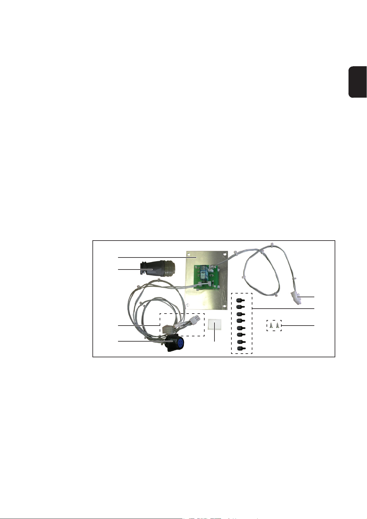
Abb.1 Lieferumfang Einbauset External Start Signal
(A) 4-polige Amphenolbuchse
(B) Verteiler (2 x 6-poliger Molexstecker)
(C) Gegenstecker
(D) Montageblech mit Relais
(E) 12-poliger Molexstecker X10
(F) 8 Distanzen M4 x 10 mm
(G) 2 Blechschrauben
(H) Klebeetikette External Start
(I) 6 Kabelbinder (ohne Abbildung)
(E)
(F)
(G)
(H)
1
Page 6

WARNUNG! Fehlerhaft durchgeführte Arbeiten können schwerwiegende Sachund Personenschäden verursachen. Nachfolgend beschriebene Tätigkeiten
dürfen nur von geschultem Fachpersonal durchgeführt werden! Beachten Sie
die Sicherheitsvorschriften in der Bedienungsanleitung der Stromquelle.
WARNUNG! Ein Elektroschock kann tödlich sein. Vor Öffnen des Gerätes:
- Netzschalter der Stromquelle in Stellung - O - schalten
- Stromquelle vom Netz trennen
- Deutlich lesbares und verständliches Warnschild gegen Wiedereinschalten
anbringen
Nach dem Öffnen des Gerätes gegebenenfalls spannungsführende Bauteile
(z.B. Kondensatoren) entladen.
Einbauset External Start Signal einbauen
Sicherheit
Vorbereitung
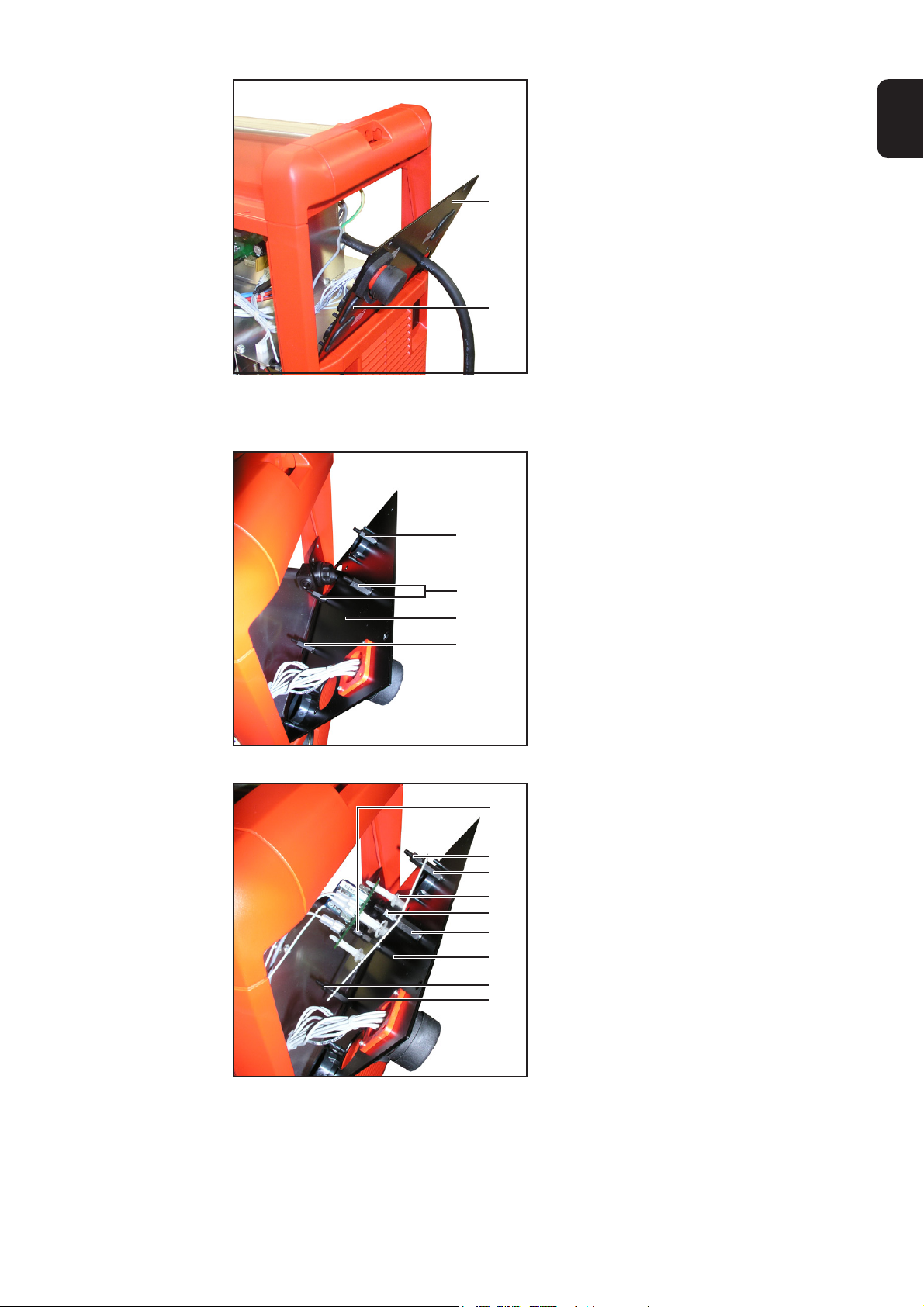
(1)
Abb.2 rechten Seitenteil entfernen
(3) (3)
1. 5 Schrauben TX20 (1) entfernen
2. Rechten Seitenteil (2) abnehmen
(1)
(2)
(1)
(1)
(1)
3. 4 Schrauben TX20 (3) entfernen
(3)
Abb.3 Rückfront demontieren
2
Page 7
Vorbereitung
(Fortsetzung)
4. Rückfront (4) nach außen klappen
5. Blindabdeckung (5) entfernen
DE
(4)
(5)
Abb.4 Blindabdeckung entfernen
Einbauset External Start Signal
einbauen
Abb.5 4 Distanzen aufschrauben
(1)
(1)
(2)
(1)
(3)
(3)
(1)
(4)
(3)
(1)
(1)
1. 4 Distanzen M4 x 10 mm (1) auf
Rückfront (2) aufschrauben
2. Montageblech mit Relais (4) auf die
Distanzen M4 x 10 mm (1) aufsetzen
3. Montageblech mit Relais (4) fixieren:
4 Distanzen M4 x 10 mm (3) auf die
Distanzen M4 x 10 mm (1) aufschrauben
Abb.6 Montageblech mit Relais montieren
3
(3)
(1)
Page 8

Einbauset External Start Signal
einbauen
(Fortsetzung)
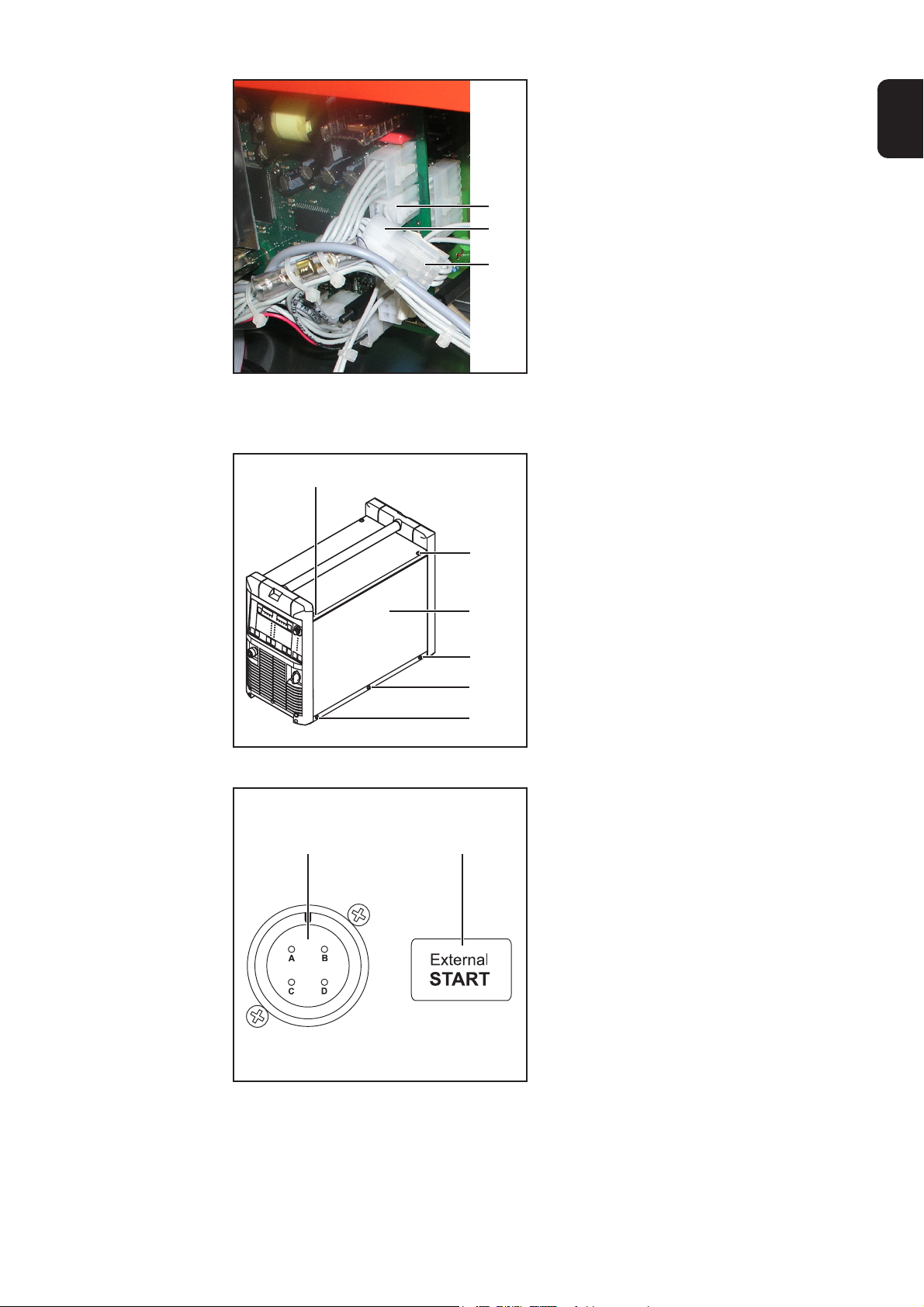
(5) (5)
Abb.7 Rückfront montieren
(6)
4. Rückfront (6) einsetzen
5. Rückfront (6) mittels 4 Schrauben
TX20 (5) fixieren
(5)
(5)
6. 4-polige Amphenolbuchse (8) von
innen in die Öffnung einsetzen
7. 4-polige Amphenolbuchse mittels 2
Blechschrauben (7) fixieren
Einbauset External Start Signal
anschließen
(7)
(8)
(7)
Abb.8 Amphenolbuchse montieren
(1) (2) (3)
1. 12-poligen Molexstecker X10 (2) vom
Einbauset External Start Signal am
Print UST (1) anstecken
2. 6-poligen Molexstecker X9 „LocalNet“
(3) vom Print UST (1) abstecken
Der 6-polige Molexstecker X9 „LocalNet“(3) befindet sich am Print UST
über X10 (auf der Abbildung vom
Kabelbaum verdeckt)
Abb.9 X10 am Print UST anstecken
4
Page 9
Einbauset External Start Signal
anschließen
(Fortsetzung)
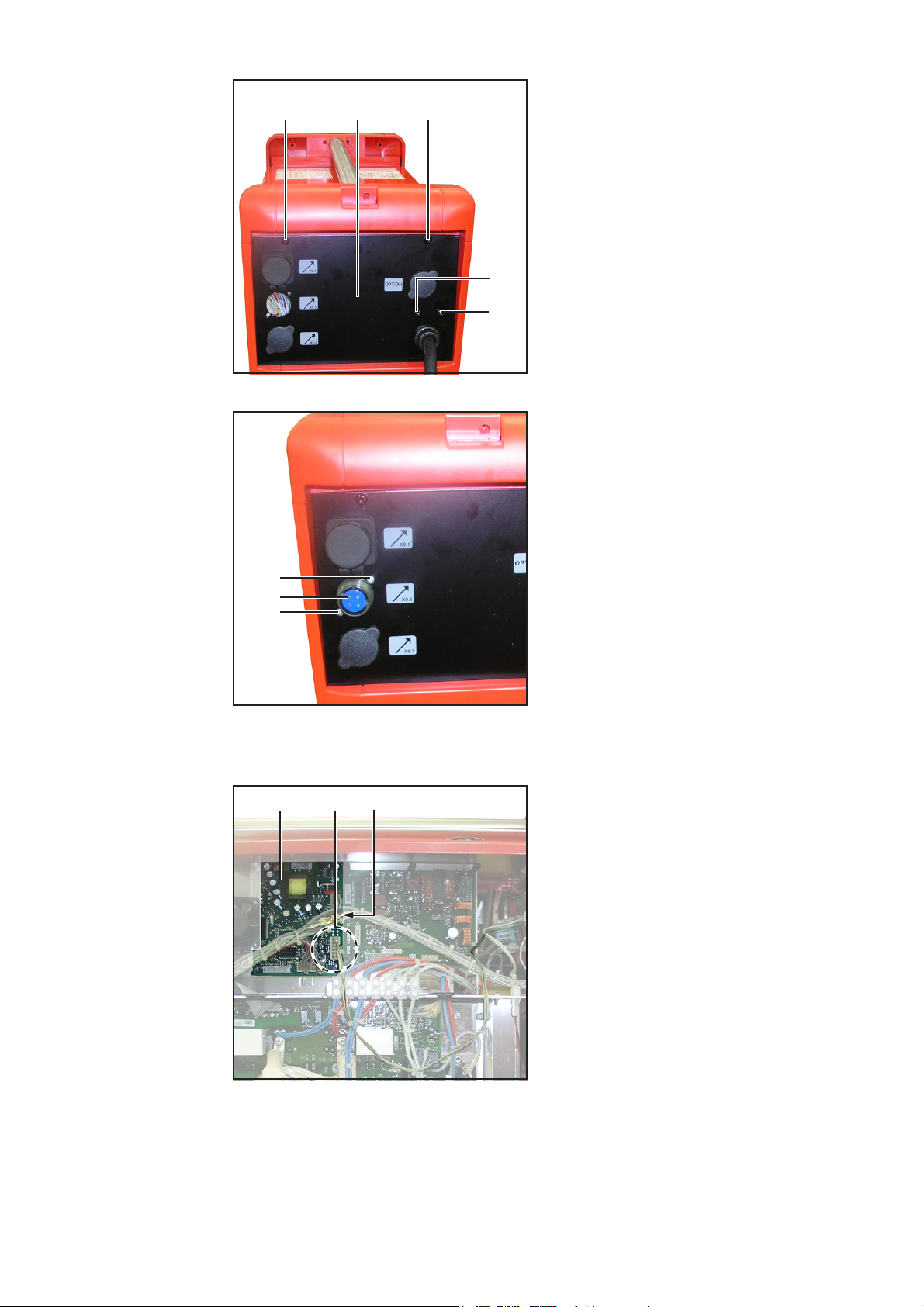
Abb.10Verteiler anstecken
(4)
(3)
(5)
3. Den 6-poligen Molexstecker des
Verteilers (4) an X9 am Print UST
anstecken
4. 6-poligen Molexstecker X9 „LocalNet“
(3) mit dem zweiten 6-poligen Molexstecker des Verteilers (5) zusammenstecken
5. Kabel vom Einbauset External Start
Signal mittels Kabelbinder am HauptKabelbaum fixieren (ohne Abbildung)
DE
Abschließende
Tätigkeiten
(1)
Abb.11rechten Seitenteil montieren
(3) (4)
1. Rechten Seitenteil (2) ansetzen
2. Rechten Seitenteil (2) mit 5 Schrauben
TX20 (1) befestigen
(1)
(2)
(1)
(1)
(1)
3. Klebeetikette External Start (4) neben
der 4-poligen Amphenolbuchse (3) an
der Rückseite der Stromquelle aufkleben
Abb.12Klebeetikette external Start aufkleben
5
Page 10

Gegenstecker
konfigurieren
Pin Belegung
A +24 V (LocalNet)
B Signaleingang +24 V SELV
(min. 30 mA)
C GND (LocalNet)
D Signaleingang GND SELV
Abb.13Anschlussbelegung der 4-poligen Amphe-
nolbuchse
Den mitgelieferten Gegenstecker entsprechend folgender Möglichkeiten konfigurieren:
a) Spannung +24 V SELV vorhanden:
b) Spannung +24 V SELV nicht vorhan-
den:
A
B
+24 V SELV
C
D
GND
A
GND
B
C
+24 V LocalNet
D
6
Page 11

Dear Reader
Introduction
Thank you for choosing Fronius - and congratulations on your new, technically highgrade Fronius product! This instruction manual will help you get to know your new
machine. Read the manual carefully and you will soon be familiar with all the many
great features of your new Fronius product. This really is the best way to get the most
out of all the advantages that your machine has to offer.
Please also take special note of the safety rules - and observe them! In this way, you
will help to ensure more safety at your product location. And of course, if you treat your
product carefully, this definitely helps to prolong its enduring quality and reliability - things
which are both essential prerequisites for getting outstanding results.
EN
ud_fr_st_et_00493 01/2012
Page 12

Page 13
General remarks
General remarks
System requirements
Field of application
Functional principle
Scope of supply
The External Start Signal option is used to start the welding process, regardless of whether there is:
- a torch trigger signal
- a robot control start signal
The power source must have OFFICIAL UST firmware V3.32.30 or higher for the External
Start Signal option to function properly.
The External Start Signal option is mainly used for automated applications.
- The welding process starts when there is +24 V SELV (safety extra low voltage) on
the 4-pin socket of the External Start Signal option.
- When the voltage is no longer present, the welding process is interrupted.
EN
(D)
(C)
(B)
(A)
(H)
Fig. 1 Scope of supply of External Start Signal installation set
(A) 4-pin amphenol socket
(B) Distributor (2 x 6-pin Molex plug)
(C) Mating connector
(D) Fitting panel with relay
(E) 12-pin X10 Molex plug
(F) 8 M4 x 10 mm spacers
(G) 2 self-tapping screws
(H) External Start adhesive label
(I) 6 cable ties (not shown)
(E)
(F)
(G)
1
Page 14

WARNING! Work performed incorrectly can cause serious injury and damage.
The following activities must only be carried out by trained and qualified personnel! Take note of the safety rules in the power source operating instructions.
WARNING! An electric shock can be fatal. Before opening the machine:
- Switch the power source mains switch to the „O“ position
- Unplug power source from the mains
- Attach a clearly legible and easy-to-understand warning sign to prevent
anyone switching it on again
After opening the machine, discharge any electrically charged components
(e.g. capacitors).
Fitting the External Start Signal installation set
Safety
Preparations
(1)
Fig. 2 Removing the right side panel
(3) (3)
1. Remove 5 TX20 screws (1)
2. Take off right side panel (2)
(1)
(2)
(1)
(1)
(1)
3. Remove 4 TX20 screws (3)
(3)
Fig. 3 Removing the back panel
2
Page 15

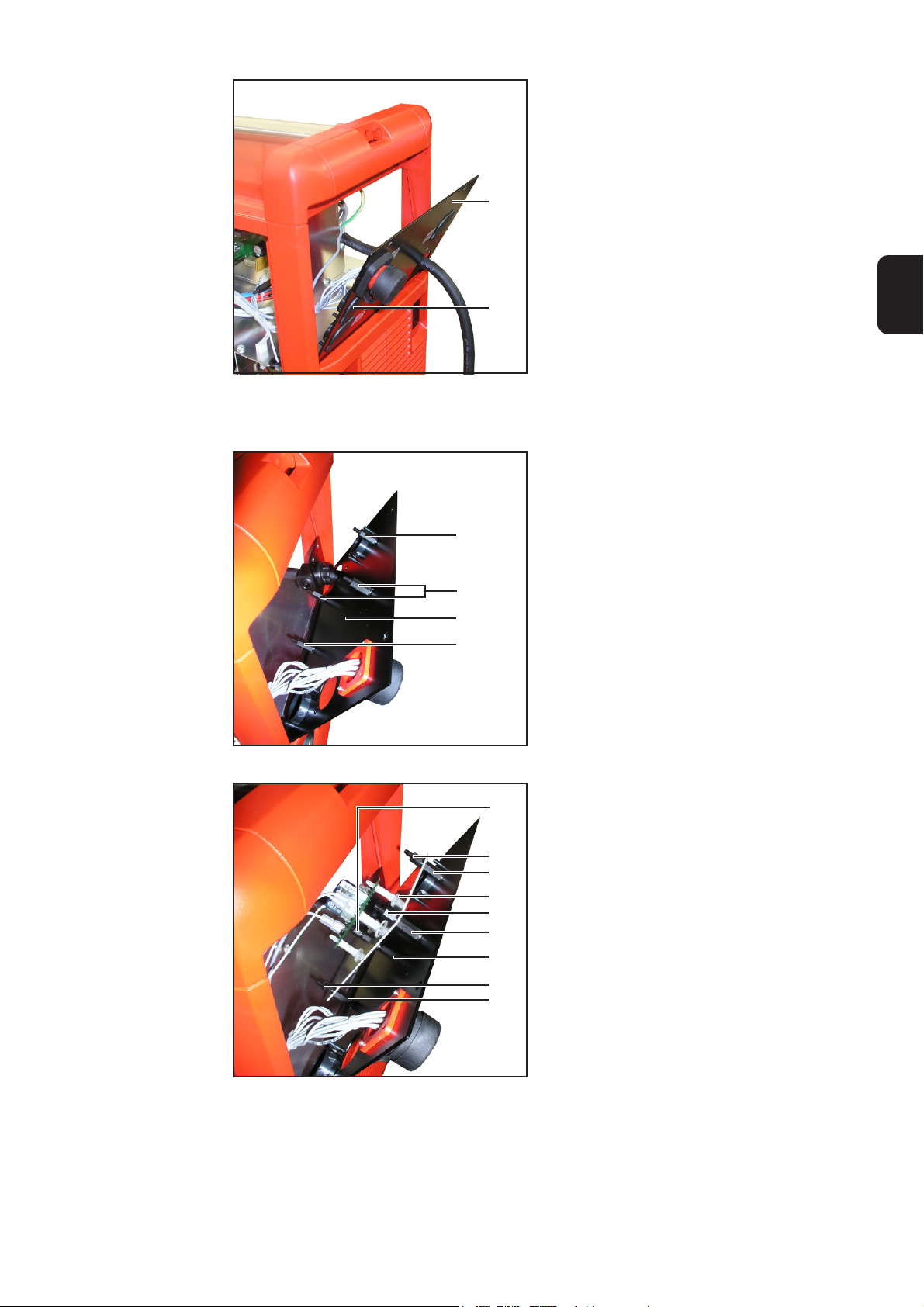
Preparations
(continued)
4. Fold out the back panel (4)
5. Remove blanking cover (5)
Fitting the External Start Signal
installation set
Fig. 4 Removing the blanking cover
(1)
(1)
(2)
(1)
(4)
(5)
EN
1. Screw 4 M4 x 10 mm spacers (1) to
back panel (2)
Fig. 5 Screw on 4 spacers
Fig. 6 Installing the fitting panel with relay
(3)
(3)
(1)
(4)
(3)
(1)
(1)
(3)
(1)
2. Place fitting panel with relay (4) onto
M4 x 10 mm spacers (1)
3. Fasten panel with relay (4):
screw 4 M4 x 10 mm spacers (3) onto
M4 x 10 mm spacers (1)
3
Page 16
Fitting the External Start Signal
installation set
(continued)
(5) (5)
Fig. 7 Fitting the back panel
(6)
4. Replace the back panel (6)
5. Fasten the back panel (6) using 4
TX20 screws (5)
(5)
(5)
6. Insert 4-pin amphenol socket (8) into
the opening from the inside
7. Fasten the 4-pin amphenol socket
using 2 self-tapping screws (7)
Connecting the
External Start
Signal installation set
(7)
(8)
(7)
Fig. 8 Fitting the amphenol socket
(1) (2) (3)
1. Connect 12-pin X10 Molex plug (2)
from the External Start Signal installation set to the UST board (1)
2. Disconnect 6-pin X9 „LocalNet“ Molex
plug (3) from the UST board (1)
The 6-pin X9 „LocalNet“ Molex plug (3)
is over X10 on the UST board (covered
by cable harness in picture)
Fig. 9 Connecting X10 to the UST board
4
Page 17

Connecting the
External Start
Signal installation set
(continued)
Fig. 10 Connecting the distributor
(4)
(3)
(5)
3. Unplug the 6-pin Molex plug on the
distributor (4) from X9 on the UST board
4. Connect the 6-pin X9 „LocalNet“ Molex
plug (3) to the second 6-pin Molex
plug on the distributor (5)
5. Attach cable from the External Start
Signal installation set to the main cable
harness using cable ties (not shown)
EN
Finally...
(1)
Fig. 11 Fitting the right side panel
(3) (4)
1. Replace the right side panel (2)
2. Fasten the right side panel (2) using 5
TX20 screws (1)
(1)
(2)
(1)
(1)
(1)
3. Stick the External Start adhesive label
(4) next to the 4-pin amphenol socket
(3) on the rear of the power source
Fig. 12 Attaching the External Start adhesive label
5
Page 18
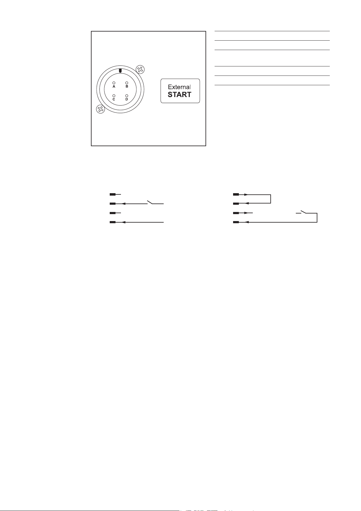
Mating connector
wiring configuration
Pin Assignment
A +24 V (LocalNet)
B Signal input +24 V SELV
(min. 30 mA)
C GND (LocalNet)
D Signal input GND SELV
Fig. 13 Pin assignment of 4-pin amphenol socket
Wire the supplied mating connector according to one of the following:
b) +24 V SELV not available:a) +24 V SELV available:
A
B
+24 V SELV
C
D
GND
A
GND
B
C
+24 V LocalNet
D
6
Page 19

Cher lecteur
Introduction
Nous vous remercions de votre confiance et vous félicitons d’avoir acheté un produit de
qualité supérieure de Fronius. Les instructions suivantes vous aideront à vous familiariser avec le produit. En lisant attentivement les instructions de service suivantes, vous
découvrirez les multiples possibilités de votre produit Fronius. C’est la seule manière
d’exploiter ses avantages de manière optimale.
Prière d’observer également les consignes de sécurité pour garantir une sécurité accrue
lors de l’utilisation du produit. Une utilisation soigneuse du produit contribue à sa longévité et sa fiabilité. Ce sont des conditions essentielles pour obtenir d’excellents résultats.
FR
ud_fr_st_et_00500 01/2012
Page 20

Page 21

Généralités
Généralités
Configuration du
système
Applications
Principe de
fonctionnement
Livraison
L’option External Start Signal sert à lancer le procédé de soudage, indépendamment des
facteurs suivants :
- un signal donné par la gâchette de la torche
- un signal de démarrage donné par une commande robot
Pour un fonctionnement optimal de l’option External Start Signal, la source de courant
doit être équipée du logiciel OFFICIAL UST V3.32.30 ou version supérieure.
L’option External Start Signal est essentiellement utilisée dans les applications automatisées.
- Si une tension de +24 V SELV (Safety Extra Low Voltage) est constatée au niveau du
connecteur 4 pôles de l’option External Start Signal, le procédé de soudage démarre.
- Lorsque la tension disparaît, le procédé de soudage s’arrête.
FR
(D)
(C)
(B)
(A)
(H)
Fig. 1 Livraison kit d’installation External Start Signal
(A) Connecteur Amphenol 4 pôles
(B) Répartiteur (2 x fiche Molex 6 pôles)
(C) Contre-fiche
(D) Tôle de montage avec relais
(E) Fiche Molex 12 pôles x 10
(F) 8 écarteurs M4 x 10 mm
(G) 2 vis à tôle
(H) Etiquette autocollante External Start
(I) 6 attache-câbles (sans figure)
(E)
(F)
(G)
1
Page 22

AVERTISSEMENT ! Les erreurs en cours d’opération peuvent entraîner des
dommages corporels et matériels graves. Les opérations décrites ci-après
doivent être effectuées exclusivement par le personnel qualifié et formé !
Respectez les consignes de sécurité figurant dans le mode d’emploi de la
source de courant.
AVERTISSEMENT ! Un choc électrique peut être mortel. Avant d’ouvrir
l’appareil :
- Commuter l’interrupteur du secteur de la source de courant sur - O -
- Débrancher la prise secteur de la source de courant
- Placer un écriteau parfaitement lisible et compréhensible sur l’appareil
pour que personne ne le rallume
Après ouverture de l’appareil, le cas échéant, décharger les éléments conducteurs de tension (par ex. condensateurs).
Mise en place du kit d’installation External Start Signal
Sécurité
Préparation
(1)
Fig. 2 Enlever la partie latérale droite
(3) (3)
1. Enlever 5 vis TX20 (1)
2. Retirer la partie latérale droite (2)
(1)
(2)
(1)
(1)
(1)
3. Enlever 4 vis TX20 (3)
(3)
Fig. 3 Démonter le panneau arrière
2
Page 23
Préparation
(Suite)
4. Rabattre le panneau arrière (4) vers
l’extérieur
5. Retirer la fausse prise (5)
(4)
Mise en place du
kit d’installation
External Start
Signal
Fig. 4 Enlever la fausse prise
(1)
(1)
(2)
(1)
(5)
FR
1. Visser 4 écarteurs M4 x 10 mm (1) sur
le panneau arrière (2)
Fig. 5 Visser 4 écarteurs
(3)
(3)
(1)
(4)
(3)
(1)
(1)
(3)
(1)
Fig. 6 Mettre en place la tôle de montage avec
relais
2. Mettre en place la tôle de montage
avec relais (4) sur les écarteurs M4 x
10 mm (1)
3. Fixer la tôle de montage avec relais
(4) :
Visser 4 écarteurs M4 x 10 mm (3) sur
les écarteurs M4 x 10 mm (1)
3
Page 24

Mise en place du
kit d’installation
External Start
Signal
(Suite)
(5) (5)
Fig. 7 Monter le panneau arrière
(6)
4. Remettre en place le panneau arrière (6)
5. Fixer le panneau arrière (6) au moyen
de 4 vis TX20 (5)
(5)
(5)
6. Mettre en place le connecteur Amphenol 4 pôles (8) de l’intérieur dans
l’ouverture
7. Fixer le connecteur Amphenol au
moyen de 2 vis à tôle (7)
Raccorder le kit
d’installation
External Start
Signal
(7)
(8)
(7)
Fig. 8 Monter le connecteur Amphenol
(1) (2) (3)
1. Brancher la fiche Molex X10 12 pôles
(2) du kit d’installation External Start
Signal au circuit imprimé UST (1)
2. Débrancher la fiche Molex X9 6 pôles
„LocalNet“ (3) du circuit imprimé UST (1)
La fiche Molex X9 6 pôles „LocalNet“
(3) se trouve sur le circuit imprimé
UST au-dessus de X10 (cachée sur la
figure par le faisceau de câbles)
Fig. 9 Brancher X10 au circuit imprimé UST
4
Page 25

Raccorder le kit
d’installation
External Start
Signal
(Suite)
Fig. 10 Brancher le répartiteur
(4)
(3)
(5)
3. Brancher la fiche Molex 6 pôles du
répartiteur (4) au X9 sur le circuit
imprimé UST
4. Raccorder la fiche Molex X9 6 pôles
„LocalNet“ (3) à la deuxième fiche
Molex 6 pôles du répartiteur (5)
5. Fixer le câble du kit d’installation
External Start Signal au faisceau de
câbles principal au moyen d’un attache-câbles (pas de figure)
FR
Étapes finales
(1)
Fig. 11 Monter la partie latérale droite
(3) (4)
1. Remettre en place la partie latérale
droite (2)
2. Fixer la partie latérale droite (2) avec 5
vis TX20 (1)
(1)
(2)
(1)
(1)
(1)
3. Coller l’étiquette autocollante External
Start (4) à côté du connecteur Amphenol 4 pôles (3) sur la face arrière de la
source de courant
Fig. 12 Coller l’étiquette autocollante External
Start
5
Page 26

Configurer la
contre-fiche
Broche Affectation
A +24 V (LocalNet)
P Entrée signal +24 V SELV
min. 30 mA)
C GND (LocalNet)
D Entrée signal GND SELV
Fig.13 Schéma de connexion du connecteur
Amphenol 4 pôles
Configurer la contre-fiche fournie en fonction des possibilités suivantes :
b) tension +24 V SELV non disponible :a) tension +24 V SELV disponible :
A
P
+24 V SELV
C
D
GND
A
GND
P
C
+24 V LocalNet
D
6
Page 27

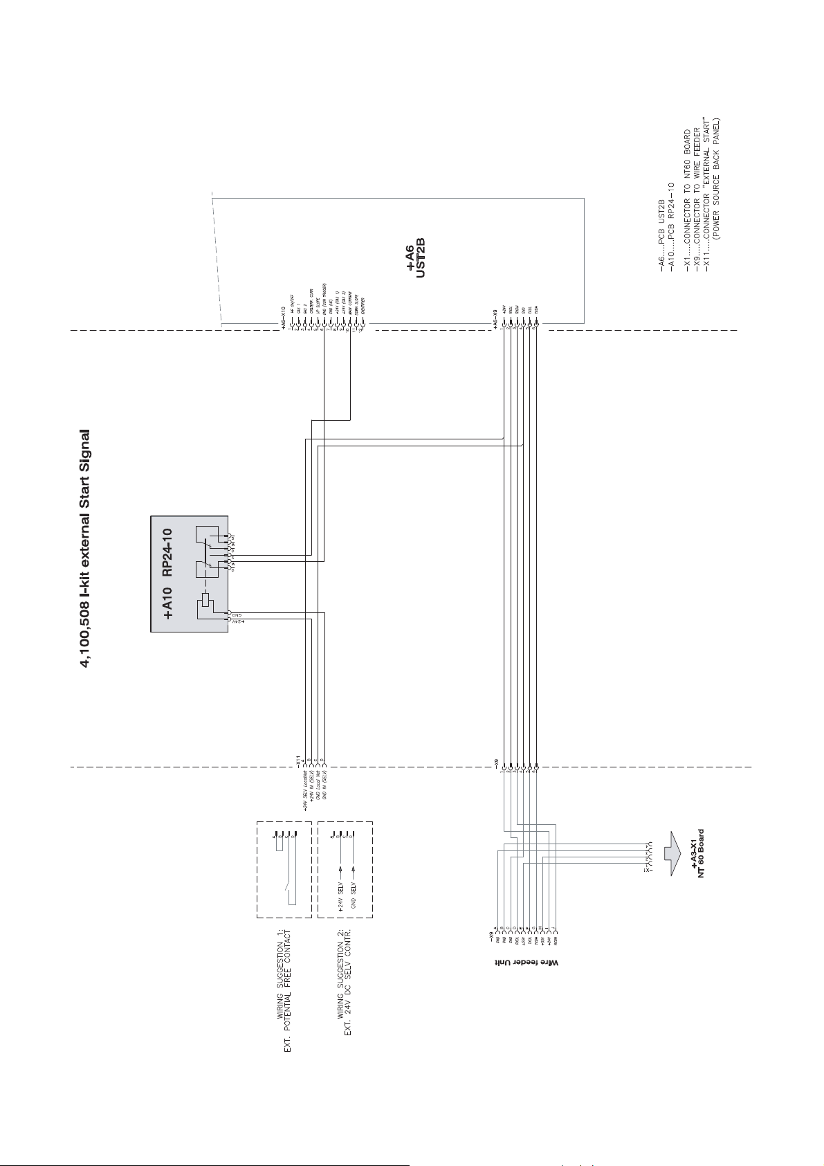
Schaltplan
DEENFRITESPT-BRNLNOCSRUSKSVTR
Circuit Diagram
Schéma de connexions
Schema
Esquema de cableado
Esquema de conexões
Bedradingsschema
Koblingsplan
Schéma zapojení
Электрическая схема
ud_fr_st_tb_00151 012012
Schéma zapojenia
Kopplingsschema
Baðlantý þemasý
Schemat połączeń
PL
Page 28
Page 29

FRONIUS INTERNATIONAL GMBH
Froniusplatz 1, A-4600 Wels, Austria
Tel: +43 (0)7242 241-0, Fax: +43 (0)7242 241-3940
E-Mail: sales@fronius.com
www.fronius.com
Under http://www.fronius.com/addresses you will find all addresses
www.fronius.com/addresses
of our Sales & service partners and Locations.
ud_fr_st_so_00082 012011
 Loading...