

Fronius External current flow signal, external speed control Installation Instruction [DE, EN, FR]
Page 1

/ Battery Charging Systems / Welding Technology / Solar Electronics
Externes Stromflußsignal
Externe Drehzahlregelung
External current flow signal
External speed control
Signal ext. de conduction de courant
Réglage externe du nombre de tours
Einbauanleitung
Ersatzteilliste
DEENFR
MIG/MAG Systemerweiterung
Installation Instructions
Spare Parts List
MIG/MAG system extension
Instructions d’installation
Liste de pièces de rechange
Extension système MIG/MAG
42,0410,0571 001-06042012
Page 2

Page 3

Einbauanleitung externes Stromfluss-Signal
Allgemeines Durch den Einbau eines externen Stromfluss-Signals und einer externen Drehzahlrege-
lung können Geräte der Serie VS 3400/4000/5000 in automatische Schweißabläufe
eingebunden werden.
DE
Sicherheit
Benötigtes Material
Warnung! Fehlerhaft durchgeführte Arbeiten können schwerwiegende Sach- und
Personenschäden verursachen. Nachfolgend beschriebene Tätigkeiten dürfen
nur von Fronius-geschultem Fachpersonal durchgeführt werden! Beachten Sie
die Sicherheitsvorschriften in der Bedienungsanleitung der Stromquelle.
Warnung! Ein Elektroschock kann tödlich sein. Vor Öffnen des Gerätes:
- Netzschalter der Stromquelle in Stellung „O“ schalten
- Stromquelle vom Netz trennen
(2)
(1)
(4)
(5)
(6)
(3)
Abb.1 Einbauset Externes Stromflußsignal
(7)
(1) .........................Print RPI ..................................................................................... 1 Stk.
(2) .........................Anschlußbuchse Robotersteuerung ............................................ 1 Stk.
(3) .........................Molex Kontankte ......................................................................... 1 Stk.
(4) .........................Kabelbinder.................................................................................5 Stk.
(5) .........................Distanz Print ................................................................................4 Stk.
(6) .........................Schraube Extrude-Tite ................................................................ 2 Stk.
(7) .........................Klemmleiste 2,5 mm ................................................................... 1 Stk.
1
Page 4

Einbauset montieren
1. Rechtes und linkes Seitenteil der
Stromquelle abnehmen.
2. Bohrungen für Print RPI (1) und
Anschlußbuchse (2) mittels beiliegender Bohrschablone herstellen.
3. Print RPI mittels Distanz Print (5) an
der vorgesehenen Stelle befestigen.
4. Anschlußbuchse (2) in die vorgesehene Bohrung stecken und von der
Rückseite mittels Schrauben ExtrudeTite (6) festschrauben
Abb. 2 Stecker montieren und Print einbauen
Einbauset anschliessen
Abb. 3 Print RPI anschließen
1. Molex-Stecker „X2“ vom Print SRK 57 abstecken.
2. Molex-Kontakte (3) vom Print RPI (1) laut nachstehender Tabelle am Molex-Stecker
anschließen.
RPI 6-pol. Molex SRK 57 16-pol. Molex Verwendung
X1/1 X2/16 Digital-Ground
X1/2 X2/13 + 15 Volt *
X1/3 — —
X1/4 X2/10 Reset-Relais-Steuerausgang
X1/5 X2/8 Reset-Eingang
X1/6 X2/7 Stromfluß-Relais-Steuerausgang
* Leitung auftrennen und laut Schaltplan mittels Klemmleiste (7) anschließen
3. Molex-Stecker am Print SR 57 anstecken
2
Page 5

Einbauset anschliessen
(Fortsetzung)
DE
Abb. 4 Ausschnitt Stromlaufplan VS 3400/4000/5000
Abb. 5 Belegung Amphenolstecker
Einbau auf Funktionsfähigkeit prüfen
Reset in: Bügel von PIN B auf PIN F
am Amphenol-Stecker: Maschine muß
stoppen.
Reset out: Abstecken eines Temperaturfühlers (2poliger Molexstecker
X10): Verbindung PIN A - PIN E muß
einen Durchgang haben.
Stromfluß: bei Belastung (Schweißen
oder statisch):Verbindung PIN C - PIN
D muß einen Durchgang haben.
Abb. 6 Reset out Temperaturfühler abstecken
3
Page 6

Einbauanleitung externe Drehzahlregelung
Benöigtes Material
Einbau VS 3400/
4000/5000
Die Option Externe Drehzahlregelung
kann in die Typen VST 3400/4000/5000
sowie in den Vorschub VR 3000/3300
eingebaut werden.
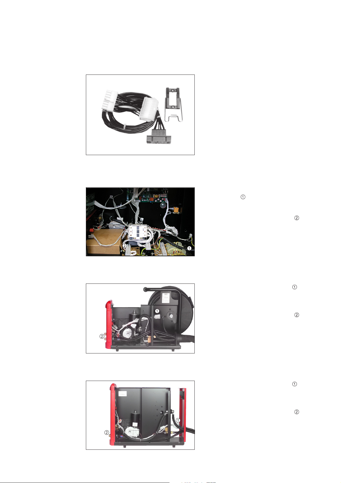
Abb. 7 Kabelbaum Externe Drehzahlregelung
1. Den Kabelbaum vom Optionsset bei
zwischen den bestehenden Kabel-
baum stecken.
2. Alten Tuchelstecker abmontieren
und den neuen Stecker vom Optionsset einbauen.
Einbau VR 3000
Einbau VR 3300
Abb.8 Montage in VS 3400/4000/5000
1. Den Kabelbaum der externen Dreh-
zahlregelung an den Stecker im VR
3000 anstecken.
2. Alten Tuchelstecker abmontieren
und den neuen Stecker vom Optionsset einbauen.
Abb.9 Montage im VR 3000
1. Den Kabelbaum der externen Dreh-
zahlregelung an den Stecker im VR
3300 anstecken.
2. Alten Tuchelstecker abmontieren
und den neuen Stecker vom Optionsset einbauen.
Abb. 10 Montage im VR 3300
4
Page 7

Einbauset anschliessen
Belegung Tuchelstecker
PIN Bezeichnung Verwendung
X7/1 PP MOTOR + Keine Verwendung bei externer Drehzahlregelung
X7/2 + 5 V + 5 Volt
X7/3 COMMAND VALUE Drehzahl-Steuereingang
X7/4 NC nicht belegt
X7/5 GUN TRIGGER 2 Taster 2
X7/6 PP MOTOR - Keine Verwendung bei externer Drehzahlregelung
X7/7 GND Masse
X7/8 NC nicht belegt
X7/9 GUN TRIGGER 1 Taster 1
DE
(1)
Abb.11 Kabelbaum Externe Drehzahlregelung
(1): Über X7/3 vom Tuchelstecker kann der Vorschubmotor mit einem Potentiometer
gesteuert werden.
5
Page 8

6
Page 9

Installation instructions for external current flow signal
General remarks
Safety
Material required:
When an esternal current flow signal and an external speed control are installed, machines of the VS 3400/4000/5000 series can be integrated into automatic welding procedures.
Warning! Maloperation can cause severe damages to persons and objects. The
following work may only be carried out by skilled personnel trained by Fronius!
Observe the safety rules in the Operating Instructions of your power source
Warning! Electrical shock can kill. Before installation:
- Switch mains switch of the power source to position „O“
- Unplug mains plug of the power source
(2)
(1)
EN
(4)
(5)
(6)
(3)
Fig.1 Conversion kit: External current flow signal
(1) .........................Print RPI .................................................................................... 1 pcs.
(2) .........................Robot trigger system connection socket .................................... 1 pcs.
(3) .........................Molex contacts ........................................................................... 1 pcs.
(4) .........................Cable tie ..................................................................................... 5 pcs.
(5) .........................Print spacer ................................................................................ 4 pcs.
(6) .........................Extrude-Tite screw ..................................................................... 2 pcs.
(7) .........................Connector block 2.5 mm ............................................................ 1 pcs.
(7)
1
Page 10

Mounting the
installation kit
1. Remove the right and left side piece
of the power source.
2. Make drill holes for Print RPI (1) and
connection socket (2) using the
enclosed drilling template.
3. Fasten the Print RPI to the location
provided using the Print spacer (5).
4. Insert connection socket (2) in the
drill hole provided and screw tight
from the back using the Extrude-Tite
screws (6).
Fig. 2 Mounting the plug and installing the RPI
board
Connect the
installation kit
Fig. 3 Connect Print RPI
1. Unplug „X2“ Molex plug from the Print SRK 57.
2. Connect the Molex-contacts (3) from the Print RPI (1) to the Molex-Plug in accordance with the the following table.
RPI 6-pole Molex to SRK 57 16-pole Molex For:
X1/1 X2/16 Digital-Ground
X1/2 X2/13 + 15 Volt *
X1/3 — —
X1/4 X2/10 Reset relay control output
X1/5 X2/8 Reset input
X1/6 X2/7 Current-flow relay control output
* Split the wire and connect using the connector block (7) as per the wiring diagram.
3. Plug the Molex-plug to the Print SR 57
2
Page 11

Connect the
installation kit
(continued)
EN
Fig. 4 Excerpt from VS 3400/4000/5000 circuit diagram
Fig. 5 Amphenol plug assignment
Perform a function check
Reset in: Jumper from PIN B to
PIN F on the Amphenol plug:
machine should stop.
Reset out: Unplug one temperature
sensore (2-pole Molex plug X10):
Connection PIN A - PIN E must
have continuity.
Current flow: When under load
(welding or static): Connection PIN
C - PIN D must have continuity.
Fig. 6 Reset out: Unplug temperature sensor
3
Page 12

Installation instructions for external speed control
Material required
Installation in VS
3400/4000/5000
The Option Externe Drehzahlregelung can
be installed into VST 3400/4000/5000 and
VR 3000/3300
Fig. 7 Cable harness for external speed control
1. Plug the calbe harness from the
option kit between the existing cable
harness at point .
2. Dismount the old Tuchel plug and
fit the new plug from the option kit.
Installation in VR
3000
Installation in VR
3300
Fig.8 How to install in VS 3400/4000/5000
1. Plug the cable harness of the exter
nal speed control onto the plug in the
VR 3000.
2. Dismount the old Tuchel plug and
fit the new plug from the option kit.
Fig. 9 How to install in VR 3000
1. Plug the cable harness of the exter
nal speed control onto the plug in the
VR 3300.
2. Dismount the old Tuchel plug and
fit the new plug from the option kit.
Fig. 10 How to install in VR 3300
4
Page 13

Connect the
installation kit
Assignment of Tuchel plug
PIN Designation Used for
X7/1 PP MOTOR + Not used where there is external speed control
X7/2 + 5 V + 5 Volt
X7/3 COMMAND VALUE Speed control input
X7/4 NC Vacant
X7/5 GUN TRIGGER 2 Button 2
X7/6 PP MOTOR - Not used where there is external speed control
X7/7 GND Earth
X7/8 NC Vacant
X7/9 GUN TRIGGER 1 Button 1
EN
(1)
Fig. 11 Cable harness for external speed control
(1): The wirefeeder motor can be potentiometer-controlled via X7/3 of the Tuchel plug.
5
Page 14

6
Page 15

Instructions d’installation signal externe de conduction de courant
Généralités Par l’installation d’un signal externe de conduction de courant et d’un réglage externe du
nombre de tours il est possible d’intéger les apareils de la série VS 3400/4000/5000
dans des séquences de soudage automatique.
FR
Sécurité
Éléments requis
Avertissement! Des travaux mal effectués peuvent entraîner de graves domma-
ges matériels et corporels. Les opérations décrites ci-après peuvent uniquement
être réalisées par des techniciens Fronius qualifiés ! Respectez les consignes de
sécurité!
Avertissement! Un électrochoc peut être mortel! Avant l’installation
- mettez l’interrupteur principal de la source de courant sur “0”
- retirez la prise
(2)
(1)
(4)
(5)
(6)
(3)
Fig.1 Set d’installation du signal externe de conduction de courant
(1) .........................Carte RPI ...........................................................................................1
(2) .........................Fiche de raccordement pour la commande robot .............................. 1
(3) .........................Connecteur Molex .............................................................................. 1
(4) .........................Attaches-câbles ................................................................................. 5
(5) .........................Écarteurs pour la carte ...................................................................... 4
(6) .........................Vis Extrude-Tite ................................................................................. 2
(7) .........................Bornier 2,5 mm .................................................................................. 1
(7)
1
Page 16

Monter
l’instructions de
transformation
1. Enlevez le panneau gauche et le
panneau droit de la source de courant.
2. Faites un trou pour la carte RPI (1) et
la fiche de raccordement (2) en
utilisant le gabarit joint à la livraison.
3. Fixez la carte RPI à l’emplacement
prévu en utilisant les écarteurs (5).
4. Placez la fiche de raccordement (2)
dans le trou prévu à cet effet et fixez
au dos avec les vis Extrude-Tite (6).
Fig. 2 Monter la prise et installer la plaquette à
circuits imprimés
Brancher
l’instructions de
transformation
Fig. 3 Raccorder la carte RPI
1. Débranchez la fiche Molex « X2 » de la carte SRK 57.
2. Raccordez les connecteurs Molex (3) de la carte RPI (1) à la fiche Molex conformément au tableau ci-après.
RPI Molex à 6 broches sur SRK 57. Molex à 16 broches Utilisation
X1/1 X2/16 Digital-Ground
X1/2 X2/13 + 15 Volt *
X1/3 — —
X1/4 X2/10 Sortie de commande
du relais de remise à
zéro
X1/5 X2/8 Entrée de remise à zéro
X1/6 X2/7 Sortie de commande
du relais de nduction de
courant
* Séparez le câble et raccordez en utilisant le bornier (7) et en respectant le schéma des
connexions
3. Branchez la fiche Molex à la carte SR 57
2
Page 17

Brancher
l’instructions de
transformation
(suite)
FR
Fig. 4 Détail du schéma des connexions VS 3400/4000/5000
Fig. 5 Occupation de la prise Amphenol
Vérifier le bon fonctionnement de
l’installation
Remise à zéro en: Archet de PIN B
à PIN F sur la prise Amphenol: La
machine doit s’arrêter
Remise á zéro out: Déconnecter
une sonde de température (prise
Molex à 2 broches X10): La liaison
PIN A - PIN E doit être parcourue
par le courant.
Conduction de courant en cas de
charge (soudage ou statique): La
liaison PIN C - PIN D doit être
parcourue par le courant.
Fig. 6 Remise à zéro out. Déconnecter la sonde de température
3
Page 18
Instructions d’installation réglage externe du nombre
de tours
Éléments requis
Montage dans VS
3400/4000/5000
L’option de réglage externe du nombre de
tours peut être installée dans les types
VST 3400/4000/5000 et dans l’avance VR
3000/3300.
Fig. 7 Faisceau de câbles réglage externe du
nombre de tours
1. Insérer le faisceau de câbles du set
d’option à dans le faisceau de
câbles existant.
2. Démonter la vielle prise Tuchel et
installer la nouvelle prise du set
d’option.
Installation VR
3000
Installation VR
3000
Fig.8 Montage dans VS 3400/4000/5000
1. Enficher le faisceau de câbles du
réglage externe du nombre de tours
dans la prise dans VR 3000.
2. Démonter la vielle prise Tuchel et
installer la nouvelle prise du set
d’option.
Fig. 9 Montage dans VR 3000
1. Enficher le faisceau de câbles du
réglage externe du nombre de tours
dans la prise dans VR 3300.
2. Démonter la vielle prise Tuchel et
installer la nouvelle prise du set
d’option.
Fig. 10 Montage dans VR 3300
4
Page 19

Brancher
l’instructions de
transformation
Occupation prise Tuchel
PIN Désignation Utilisation
X7/1 PP MOTOR + Non utilisé avec réglage externe du nombre de tours
X7/2 + 5 V + 5 volts
X7/3 COMMAND VALUE Entrée de commande du nombre de tours
X7/4 NC Non occupé
X7/5 GUN TRIGGER 2 Touche 2
X7/6 PP MOTOR - Non utilisé avec réglage externe du nombre de tours
X7/7 GND Masse
X7/8 NC Non occupé
X7/9 GUN TRIGGER 1 Touche 1
FR
(1)
Fig.11 Faisceau de câbles réglage externe du nombre de tours
(1): Moyennant X7/3 de la prise Tuchel on peut commander le moteur d’avance par un
potentiomètre
5
Page 20

6
Page 21

Page 22

Bohrschablone/Drilling pattern/Gabarit de perçage
Page 23

Page 24

FRONIUS INTERNATIONAL GMBH
Froniusplatz 1, A-4600 Wels, Austria
Tel: +43 (0)7242 241-0, Fax: +43 (0)7242 241-3940
E-Mail: sales@fronius.com
www.fronius.com
Under http://www.fronius.com/addresses you will find all addresses
www.fronius.com/addresses
of our Sales & service partners and Locations.
ud_fr_st_so_00082 012011
 Loading...