

Page 1

/ Perfect Charging / Perfect Welding / Solar Energy
EtherCAT
EtherCAT extern
Einbauanleitung
DEENFR
Roboter-Option
Installation instructions
Robot option
Instructions d'installation
Option robot
42,0410,1813 005-09072014
Page 2

0
Page 3

Sehr geehrter Leser
Einleitung Wir danken Ihnen für Ihr entgegengebrachtes Vertrauen und gratulieren Ihnen zu Ihrem
technisch hochwertigen Fronius Produkt. Die vorliegende Anleitung hilft Ihnen, sich mit
diesem vertraut zu machen. Indem Sie die Anleitung sorgfältig lesen, lernen Sie die vielfältigen Möglichkeiten Ihres Fronius-Produktes kennen. Nur so können Sie seine Vorteile
bestmöglich nutzen.
Bitte beachten Sie auch die Sicherheitsvorschriften und sorgen Sie so für mehr Sicherheit
am Einsatzort des Produktes. Sorgfältiger Umgang mit Ihrem Produkt unterstützt dessen
langlebige Qualität und Zuverlässigkeit. Das sind wesentliche Voraussetzungen für hervorragende Ergebnisse.
DE
1
Page 4

2
Page 5

Inhaltsverzeichnis
Allgemeines ............................................................................................................................................... 5
Sicherheit.............................................................................................................................................. 5
Gerätekonzept ...................................................................................................................................... 5
Funktionsprinzip.................................................................................................................................... 5
Anschlüsse am Interface - TSt Geräteserie.......................................................................................... 5
Anwendungsbeispiel............................................................................................................................. 6
Anwendungsbeispiel für externe Variante ............................................................................................ 6
Hinweise zum Einbau der externen Variante........................................................................................ 7
Feldbus-Koppler anschließen .................................................................................................................... 8
Sicherheit.............................................................................................................................................. 8
Allgemeines .......................................................................................................................................... 8
Anschlüsse am Feldbus-Koppler BK1120 ............................................................................................8
Anschlüsse am Feldbus-Koppler BK1120 - externe Variante............................................................... 8
Interface EtherCAT anschließen - TSt Geräteserie .............................................................................. 9
Interface EtherCAT anschließen - TS/TPS, MW/TT Geräteserie ......................................................... 9
EtherCAT Kabel und Steckverbinder.................................................................................................... 10
Fehlerdiagnose, Fehlerbehebung .............................................................................................................. 11
Sicherheit.............................................................................................................................................. 11
Anzeigen am Feldbus-Koppler BK1120................................................................................................ 11
LEDs zur Diagnose der Spannugsversorgung...................................................................................... 11
LEDs zur Diagnose der EtherCAT State Machine/PLC........................................................................ 12
LEDs zur Feldbus-Diagnose................................................................................................................. 12
LEDs zur Diagnose des K-Bus ............................................................................................................. 12
Eigenschaften der Datenübertragung und technische Daten .................................................................... 15
Eigenschaften der Datenübertragung................................................................................................... 15
Sicherheitseinrichtung........................................................................................................................... 15
Technische Daten des Feldbus-Kopplers BK1120 ............................................................................... 15
Signalbeschreibung EtherCAT................................................................................................................... 17
Allgemeines .......................................................................................................................................... 17
Betriebsarten der Stromquelle - TSt Geräteserie.................................................................................. 17
Betriebsarten der Stromquelle - TS/TPS, MW/TT Geräteserie............................................................. 17
Übersicht............................................................................................................................................... 17
Ein- und Ausgangssignale für MIG/MAG - TSt Geräteserie ...................................................................... 18
Eingangssignale.................................................................................................................................... 18
Ausgangssignale................................................................................................................................... 18
Ein- und Ausgangssignale für MIG/MAG Standard-/Puls-Synergic und CMT ........................................... 20
Allgemeines .......................................................................................................................................... 20
Eingangssignale.................................................................................................................................... 20
Ausgangssignale................................................................................................................................... 21
Ein- und Ausgangssignale für WIG............................................................................................................ 23
Allgemeines .......................................................................................................................................... 23
Eingangssignale.................................................................................................................................... 23
Betriebsarten der Stromquelle .............................................................................................................. 24
Einstellung Pulsbereich......................................................................................................................... 24
Ausgangssignale................................................................................................................................... 24
Ein- und Ausgangssignale für CC/CV........................................................................................................ 26
Allgemeines .......................................................................................................................................... 26
Eingangssignale.................................................................................................................................... 26
Ausgangssignale................................................................................................................................... 27
Ein- und Ausgangssignale für Standard-Manuell....................................................................................... 28
Allgemeines .......................................................................................................................................... 28
Eingangssignale.................................................................................................................................... 28
Ausgangssignale................................................................................................................................... 29
DE
Appendix 89
Circuit diagrams: EtherCAT ....................................................................................................................... 90
Circuit diagrams: EtherCAT extern ............................................................................................................ 91
3
Page 6

4
Page 7
Allgemeines
DE
Sicherheit
Gerätekonzept EtherCAT ist ein von der Firma Beckhoff initiiertes offenes Feldbus-System auf der Basis
von Ethernet. Seine Stärken liegen in extrem kurzen Zykluszeiten und exakter Synchronisierung.
Das EtherCAT zeichnet sich durch geringes Bauvolumen und hohe Modularität aus. Die
einfache und platzsparende Montage auf einer genormten C-Schiene sowie die direkte
Verdrahtung von Aktoren und Sensoren ohne Querverbindungen zwischen den Klemmen
standardisiert die Installation. Das einheitliche Beschriftungskonzept erleichtert zusätzlich
die Installation.
WARNUNG! Alle in dieser Bedienungsanleitung angeführten Arbeiten dürfen nur
von geschultem Fachpersonal durchgeführt werden. Alle in dieser Bedienungsanleitung beschriebenen Funktionen dürfen nur von geschultem Fachpersonal
angewandt werden. Alle beschriebenen Arbeiten erst ausführen und alle beschriebenen Funktionen erst anwenden wenn folgende Dokumente vollständig
gelesen und verstanden wurden:
- Diese Bedienungsanleitung
- Sämtliche Bedienungsanleitungen der Systemkomponenten, insbesondere
Sicherheitsvorschriften
Funktionsprinzip Der im Fronius EtherCAT Roboterinterface verwendete Buskoppler BK1120 verbindet
EtherCAT mit den Beckhoff K-Busklemmen (KLxxxx). Eine Station besteht aus einem Buskoppler BK1120, einer beliebigen Anzahl von bis zu 64 K-Busklemmen (mit K-Bus-Verlängerung bis zu 255) und einer Busendklemme.
Der Buskoppler erkennt die angeschlossenen Klemmen und erstellt automatisch die Zuordnung ins Prozessabbild des EtherCAT-Systems. Mit der oberen Ethernet-Schnittstelle
wird der Buskoppler an das Netzwerk angeschlossen, die untere RJ45-Buchse dient zum
optionalen Anschluss weiterer EtherCAT-Geräte im gleichen Strang.
Im EtherCAT-Netzwerk wird der Buskoppler BK1120 im Bereich der Ethernet- Signalübertragung (100BASE-TX) an beliebiger Stelle eingesetzt, außer direkt am Switch. Für den
Einsatz am Switch sind die Buskoppler BK9000 (für K-Bus-Klemmen) bzw. EK1000 (für EBus- Klemmen) geeignet.
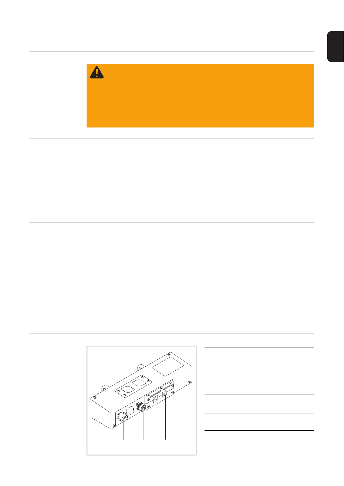
Anschlüsse am
Interface - TSt Geräteserie
(1) Anschluss LocalNet-OUT
zum Annschließen des Verbindungs-Schlauchpaketes
(2) Anschluss LocalNet-IN
zum Anschließen der Stromquelle
(3) Anschluss EtherNet RJ 45 - X1 IN
(2)
(4) Anschluss EtherNet RJ 45 - X2
OUT
(1) (4)(3)
5
Page 8

Anwendungsbeispiel
(3)
(4)
(5)
(6)
Anwendungsbeispiel für externe
Variante
(2)
(1)
(10)
(1) Kühlgerät
(2) Stromquelle
(3) EtherCAT
(4) Verbindungs-Schlauchpaket
(5) Drahtvorschub
(1)
(2)
(3)
(7)
(8)
(9)
(6) Schweißbrenner
(7) Robotersteuerung
(8) Schweißdraht-Fass
(9) Roboter
(10) Datenkabel EtherCAT
(6)
(7)
(8)
(4)
(5)
(1) Robotersteuerung
(2) EtherCAT externe Variante
(3) Datenkabel EtherCAT
(4) Stromquelle
(5) Kühlgerät
(9)
(10)
(6) Drahtvorschub
(7) Schweißbrenner
(8) Verbindungs-Schlauchpaket
(9) Roboter
(10) Schweißdraht-Fass
6
Page 9

Hinweise zum
Einbau der externen Variante
HINWEIS! Beim Einbau der externen Variante des EtherCAT Feldbus-Kopplers
BK1120 sind folgende Richtlinien zu beachten:
- Die Verlegung der Kabel hat getrennt von netzbehafteten Leitungen zu erfolgen
- Der Einbau des Feldbus-Kopplers hat getrennt von netzbehafteten Leitungen oder Komponenten zu erfolgen
- Der Feldbus-Koppler darf nur an einem vor Verschmutzung und Wasser geschützten Ort eingebaut werden
- Es ist dafür zu sorgen, dass die 24V Versorgungsspannung sicher getrennt
ist von Stromkreisen mit höherer Spannung.
DE
7
Page 10

Feldbus-Koppler anschließen
Sicherheit
Allgemeines Das Anschließen des Interface EtherCAT erfolgt am Feldbus-Koppler BK1120.
Anschlüsse am
Feldbus-Koppler
BK1120
WARNUNG! Ein elektrischer Schlag kann tödlich sein. Vor Beginn der Arbeiten
alle beteiligten Geräte und Komponenten
- ausschalten
- vom Stromnetz trennen
- gegen Wiedereinschalten sichern.
VORSICHT! Gefahr von Sachschäden. Vor Beginn der Arbeiten sicherstellen,
dass die Kabel für die externe Spannungsversorgung des Interfaces spannungsfrei sind und bis zum Abschluss aller Arbeiten spannungsfrei bleiben.
(1) Anschluss EtherNet RJ 45 - X1 IN
(2) Anschluss EtherNet RJ 45 - X2
(1)
(3)
(3) Anschlüsse DC IN
OUT
zum Anschließen der externen
Spannungsversorgung
Anschlüsse am
Feldbus-Koppler
BK1120 - externe
Variante
(2)
HINWEIS! Die externe Spannungsversorgung darf nicht über die Stromquelle erfolgen. Für die externe Spannungsversorgung Roboter oder Steuerung verwenden.
VORSICHT! Gefahr von Sachschäden. Vor Beginn der Arbeiten sicherstellen,
dass die Kabel für die externe Spannungsversorgung des Interfaces spannungsfrei sind und bis zum Abschluss aller Arbeiten spannungsfrei bleiben.
8
Page 11

(1)
(3)
(1) Anschluss EtherNet RJ 45 - X1 IN
(4)
(2) Anschluss EtherNet RJ 45 - X2
(3) Anschluss LocalNet
(5)
(4) Erdungskabel
OUT
DE
Interface
EtherCAT anschließen - TSt
Geräteserie
(2)
HINWEIS! Die externe Spannungsversorgung darf nicht über die Stromquelle erfolgen. Für die externe Spannungsversorgung Roboter oder Steuerung verwenden.
(5) Anschlüsse DC IN
zum Anschließen der externen
Spannungsversorgung
Daten-Eingangskabel EtherCAT am
1
Anschluss EtherNet RJ 45 - X1 IN (3)
anschließen
Daten-Ausgangskabel EtherCAT am
2
Anschluss EtherNet RJ 45 - X1 OUT
(4) anschließen
LocalNet-Stecker vom Verbindungs-
3
Schlauchpaket an Anschluss
LocalNet-OUT (1) anschließen
Anschluss LocalNet der Stromquelle
4
mittels LocalNet-Kabel mit Anschluss
LocalNet-IN (2) verbinden
Interface
EtherCAT anschließen - TS/
TPS, MW/TT Geräteserie
(2)
Daten-Eingangskabel EtherCAT am Anschluss EtherNet RJ 45 - X1 IN am Feldbus-
1
Koppler anschließen
Daten-Ausgangskabel EtherCAT am Anschluss EtherNet RJ 45 - X1 OUT am Feld-
2
bus-Koppler anschließen
LocalNet-Stecker vom Verbindungs-Schlauchpaket an Anschluss LocalNet am Inter-
3
face anschließen
(1) (4)(3)
HINWEIS! Solange das Roboterinterface am LocalNet angeschlossen ist, bleibt automatisch
die Betriebsart „2-Takt Betrieb“gewählt (Anzeige: Betriebsart 2-Takt
Betrieb).
Informationen zur Betriebsart „Sonder-2Takt Betrieb für Roboterinterface“ finden
Sie in der Bedienungsanleitung der Stromquelle.
9
Page 12

HINWEIS! Solange das Roboterinterface am LocalNet angeschlossen ist, bleibt
automatisch die Betriebsart „2-Takt Betrieb“gewählt (Anzeige: Betriebsart 2-Takt
Betrieb).
Informationen zur Betriebsart „Sonder-2-Takt Betrieb für Roboterinterface“ finden Sie in
der Bedienungsanleitung der Stromquelle.
EtherCAT Kabel
und Steckverbinder
Verwenden Sie zur Verbindung von EtherCAT-Geräten nur Ethernet-Kabel, die mindestens der Kategorie 5 (CAt5) nach EN 50173 bzw. ISO/IEC 11801 entsprechen. EtherCAT
nutzt 4 Adern des Kabels für die Signalübertragung.
EtherCAT verwendet RJ45-Steckverbinder. Die Kontaktbelegung ist zum Ethernet-Standard (ISO/IEC 8802-3) kompatibel.
Pin Farbe Anmerkung
1 gelb TD+ (Transmission Data Pluspol)
18
2 orange TD- (Transmission Data Minuspol)
3 weiß RD+ (Receiver Data Pluspol)
4 - Normalerweise nicht verwendet; um die Signalvollständig-
5-
keit sicherzustellen, sind diese Pins miteinander verbun-
den und enden über einen Filterkreis am Schutzleiter (PE).
6 blau RD- (Receiver Data Minuspol)
7 - Normalerweise nicht verwendet; um die Signalvollständig-
8-
keit sicherzustellen, sind diese Pins miteinander verbun-
den und enden über einen Filterkreis am Schutzleiter (PE).
Aufgrund der automatischen Kabelerkennung (Auto-Crossing) können Sie zwischen
EtherCAT- Geräten von Beckhoff sowohl symmetrisch (1:1) belegte, wie auch
Cross-Over-Kabel verwenden.
Die folgenden Beckhoff-Kabel und Steckverbinder sind für den Einsatz an EtherCAT-Systemen geeignet:
- ZB9010 (Industrial-Ethernet/EtherCAT-Kabel, feste Verlegung CAT 5e, 4-adrig)
- ZB9020 (Industrial-Ethernet/EtherCAT-Kabel schleppkettentauglich CAT 5e, 4-adrig)
- ZS1090-0003 (RJ45-Stecker, 4-polig, IP 20, feldkonfektionierbar)
- ZS1090-0005 (RJ45 Stecker, 8-polig (GigaBit geeignet), IP 20, feldkonfektionierbar)
- ZK1090-9191-0001 (0.17m EtherCAT Patch-Kabel)
- ZK1090-9191-0005 (0.5m EtherCAT Patch-Kabel)
- ZK1090-9191-0010 (1.0m EtherCAT Patch-Kabel)
- ZK1090-9191-0020 (2.0m EtherCAT Patch-Kabel)
- ZK1090-9191-0030 (3.0m EtherCAT Patch-Kabel)
- ZK1090-9191-0050 (5.0m EtherCAT Patch-Kabel)
10
Page 13

Fehlerdiagnose, Fehlerbehebung
DE
Sicherheit
Anzeigen am
Feldbus-Koppler
BK1120
WARNUNG! Ein elektrischer Schlag kann tödlich sein. Vor Beginn von Arbeiten
am Interface alle beteiligten Geräte und Komponenten
- ausschalten
- vom Netz trennen
- gegen Wiedereinschalten sichern.
(1)
(2)
(3)
(4)
(5)
(6)
(7)
(8)
(9)
(10)
LEDs zur Diagnose der Spannugsversorgung
(1) LED Run grün
(2) LED Error rot
(3) LED Link (X1 IN) gelb
(4) LED Aktiv (X1 IN) grün
(5) LED Link (X2 OUT) gelb
(6) LED Aktiv (X2 OUT) grün
(7) LED Power Supply grün
(8) LED Power Contacts grün
(9) LED I/O Run grün
(10) LED I/O Error rot
LED Anzeige Bedeutung
Power Supply Aus Keine Betriebsspannung am Buskoppler vorhanden
Leuchtet 24 VDC Betriebsspannung am Buskoppler vorhan-
Power Contacts Aus Keine Spannungsversorgung an den Powerkontak-
Leuchtet Spannungsversorgung 24 VDC an den Powerkontak-
zur Diagnose der EtherCAT State Machine/
PLC
zur Feldbus-Diagnose
zur Diagnose der Spannungsversorgung
zur Diagnose des K-Bus
den
ten vorhanden
ten vorhanden
11
Page 14

LEDs zur Diagnose der EtherCAT
State Machine/
PLC
LED Anzeige Bedeutung
Run Aus Der Buskoppler ist im Initialisierungs-Zustand
Blinkt Der Buskoppler ist im Zustand Pre-Operational
Einzelblitz Der Buskoppler ist im Zustand Safe-Operational
Leuchtet Der Buskoppler ist im Zustand Operational
Flackert Es wird eine Firmware geladen.
Error Aus Kein Fehler
Blinkt PLC-Fehler / Lost Frames
LEDs zur Feldbus-Diagnose
LED Anzeige Bedeutung
Link (X1 IN) Aus keine Verbindung auf dem ankommenden EtherCAT-
Strang
Leuchtet vorhergehender EtherCAT-Teilnehmer angeschlos-
sen
Aktiv (X1 IN) Blinkt Kommunikation mit vorhergehendem EtherCAT-
Teilnehmer
Aus keine Verbindung auf dem ankommenden EtherCAT-
Strang
Leuchtet keine Kommunikation auf dem ankommenden Ether-
CAT- Strang
Link (X2 OUT) Aus keine Verbindung auf dem weiterführenden Ether-
CAT- Strang
Leuchtet folgender EtherCAT-Teilnehmer angeschlossen
Aktiv (X2 OUT) Blinkt Kommunikation mit nachfolgendem EtherCAT- Teil-
nehmer
Aus keine Verbindung auf dem weiterführenden Ether-
CAT- Strang
Leuchtet keine Kommunikation auf dem weiterführenden
EtherCAT-Strang
LEDs zur Diagnose des K-Bus
12
LED Anzeige Bedeutung Abhilfe
I/O Run Aus K-Bus inaktiv -
Leuchtet K-Bus aktiv -
Page 15

I/O Error
Fehler-
Anzeige
Blinkt EMV Probleme - Spannungsversorgung
1 Implus 0 EEPROM-Prüfsum-
2 Impluse 0 Programmierte Kon-
3 Impulse 0 K-Bus-Kommando-
4 Impulse 0 K-Bus-Datenfehler,
5 Impulse n K-Bus-Fehler bei Re-
14 Impulse nn-te Busklemme hat
argument Bedeutung Abhilfe
auf Unter- oder Überspannungsspitzen kontrollieren
- EMV-Maßnahmen ergreifen
- Liegt ein K-Bus-Fehler
vor, kann durch erneutes
Starten (Aus- und Wiedereinschalten des Koppler) der Fehler lokalisiert
werden
Herstellereinstellung mit der
menfehler
1 Überlauf im Code
Buffer
2 Unbekannter Daten-
typ
figuration, falscher
Tabelleneintrag
n
(n > 0)
n Bruchstelle hinter
Tabellenvergleich
(Busklemme n)
fehler
Bruchstelle hinter
dem Buskoppler
Busklemme n
gister-Kommunikation mit Busklemme n
das falsche Format
Konfigurationssoftware
KS2000 setzen (Menü "Online -> Koppler -> Dienste ->
Herstellereinstellung")
Weniger Busklemmen stecken. Bei prog. Konfiguration
sind zu viele Einträge in der
Tabelle
Software Update des Buskopplers notwendig
Programmierte Konfiguration
auf Richtigkeit überprüfen
Falscher Tabelleneintrag
- Keine Busklemme gesteckt
- Eine der Busklemmen ist
defekt; angehängte Busklemmen halbieren und
prüfen ob der Fehler bei
den übrigen Busklemmen
noch vorhanden ist. Dies
weiter durchführen, bis
die defekte Busklemme
lokalisiert ist.
Prüfen ob die n+1 Busklemme
richtig gesteckt ist, gegebenenfalls tauschen
Kontrollieren ob die Busendklemme 9010 gesteckt ist
n-te Busklemme tauschen
Buskoppler erneut Starten,
falls der Fehler erneut auftritt
die Busklemme tauschen.
DE
13
Page 16

I/O Error
Fehler-
Anzeige
15 Impulse n Anzahl der Busklem-
16 Impulse n Länge der K-Bus-Da-
argument Bedeutung Abhilfe
men stimmt nicht
mehr
ten stimmt nicht
mehr
Buskoppler erneut Starten,
falls der Fehler erneut auftritt,
Herstellereinstellung mit der
Konfigurationssoftware
KS2000 setzen
Buskoppler erneut Starten,
falls der Fehler erneut auftritt,
Herstellereinstellung mit der
Konfigurationssoftware
KS2000 setzen
14
Page 17

Eigenschaften der Datenübertragung und technische Daten
Eigenschaften
der Datenübertragung
Sicherheitseinrichtung
DE
Übertragungstechnik EtherCAT
Netzwerk Topologie Stern / Linie
Medium Twistet-Pair-Kabel
Übertragungsrate 100 Mbit/s
Busanschluss EtherNet RJ 45
Prozessdaten-Breite 296 Bit (Standardkonfiguration)
Prozessdaten-Format Intel
Bei ausgefallener Datenübertragung werden alle Ein- und Ausgänge zurückgesetzt und
die Stromquelle befindet sich im Zustand „Stop“. Nach wiederhergestellter Datenübertragung erfolgt die Wiederaufnahme des Vorganges durch folgende Signale:
- Signal „Roboter ready“
- Signal „Quellen-Störung quittieren“
HINWEIS! Der Ausfall der Datenübertragung kann nur dann festgestellt werden,
wenn im Sync-Manager der Watchdog konfiguriert ist.
Technische Daten
des FeldbusKopplers BK1120
Anzahl der K-Busklemmen 64
Max. Byte-Anzahl Feldbus 1024 Byte Input / Output
Digitale Peripheriesignale 8192 Inputs / Outputs
Analoge Peripheriesignale 256 Inputs / Outputs
Protokolle EtherCAT (Direct-Mode)
Baudrate 100 MBaud
Konfiguration Konfigurations-Software KS2000, TwinCAT Sys-
tem Manager oder via EtherCAT (ADS)
Busanschluss 2 x RJ45
Spannungsversorgung 24 VDC (-15%/+20%)
Stromaufnahme ca. 100 mA
Potenzialtrennung 500 V
(Powerkontakt / Versorgungsspannung / Ether-
zulässige Umgebungstemperatur im
Betrieb
zulässige Umgebungstemperatur bei
Lagerung
zulässige relative Luftfeuchtigkeit 95%, keine Betauung
Abmessungen (B x H x T) ca. 49 mm x 100 mm x 70 mm
Montage auf 35 mm Tragschiene nach EN 50022
Vibrations- / Schockfestigkeit gemäß EN 60068-2-6 / EN 60068-2-27,
EMV-Festigkeit / Aussendung gemäß EN 61000-6-2 / EN 61000-6-4
0°C bis + 55°C
-25°C bis + 85°C
EN 60068-2-29
eff
net)
15
Page 18

Schutzart IP 20
Einbaulage beliebig
Zulassung CE, UL
16
Page 19

Signalbeschreibung EtherCAT
DE
Allgemeines
Betriebsarten der
Stromquelle - TSt
Geräteserie
Die folgenden Signalbeschreibungen gelten für ein Interface mit einer Kommunikationsklemme KL 6021-0010 (Standardausführung)
BK1120
KL6021-0010
Zusätzlich besteht die Möglichkeit, weitere Klemmen in ein Roboterinterface einzubauen.
Die Anzahl ist jedoch durch die Gehäusegröße limitiert.
HINWEIS! Beim Einbau weiterer Klemmen ändert sich das Prozess-Datenbild.
Je nach eingestellter Betriebsart kann das Interface EtherCAT verschiedene Ein- und Ausgangssignale übertragen.
Betriebsart / 1H 5H 4H 3H
MIG/MAG Standard Schweißen 0 0 0
Merkerbetrieb 0 1 0
Parameteranwahl intern 0 1 1
MIG/MAG Standard-Manuell Schweißen 1 0 0
KL9010
Betriebsarten der
Stromquelle TS/TPS, MW/TT
Geräteserie
Übersicht “Signalbeschreibung EtherCAT“ setzt sich aus folgenden Abschnitten zusammen:
Betriebsart / 1H 5H 4H 3H
MIG/MAG Standard Schweißen 0 0 0
MIG/MAG Impuls-Lichtbogen Schweißen 0 0 1
Job Betrieb 0 1 0
Parameteranwahl intern 0 1 1
MIG/MAG Standard-Manuell Schweißen 1 0 0
CC / CV 1 0 1
WIG Schweißen 1 1 0
CMT / Sonderprozess 1 1 1
- Ein- und Ausgangssignale für MIG/MAG - TSt Geräteserie
- Ein- und Ausgangssignale für MIG/MAG Standard-/Puls-Synergic und CMT
- Ein- und Ausgangssignale für WIG
- Ein- und Ausgangssignale für CC/CV
- Ein- und Ausgangssignale für Standard-Manuell
1)
die Signalbeschreibungen gelten nur im Zusammenhang mit einer Stromquelle der TS/
TPS, MW/TT Geräteserie.
1)
1)
1)
1)
17
Page 20

Ein- und Ausgangssignale für MIG/MAG - TSt Geräteserie
Eingangssignale Objekt 7000H RxPDO - Signale vom Roboter zur Stromquelle
Subindex Signalbezeichnung Datentyp Bereich
0H Anzahl der Einträge 0 - 255
1H 1H Schweißen Ein High -
2H Roboter bereit High 3H Betriebsarten Bit 0 High 4H Betriebsarten Bit 1 High 5H Betriebsarten Bit 2 High 6H Nicht in Verwendung - 7H Nicht in Verwendung - 8H Nicht in Verwendung - -
2H 1H Gas Test High -
2H Drahtvorlauf High 3H Drahtrücklauf High 4H Quellenstörung quittieren High 5H Positionssuchen High 6H Brenner ausblasen High 7H Nicht in Verwendung - 8H Nicht in Verwendung - -
9H - 16H Merker-Nummer - 0 - 5
3H 1H - 8H Nicht in Verwendung - 4H 1H - 16H Leistungs-Sollwert - 0 - 65535 (0 - 100 %)
1H - 8H Low Byte 9H - 16H High Byte -
5H 1H - 8H Lichtbogen-Längenkorrektur,
Sollwert
6H 1H - 8H Lichtbogen-Längenkorrektur,
Sollwert
9H -16H Dynamikkorrektur, Sollwert - 0 - 255 (-5 - +5 %)
7H 1H - 8H Nicht in Verwendung - 8H 1H Nicht in Verwendung - -
2H Nicht in Verwendung - -
3H Dynamikkorrektur disable High -
4H Nicht in Verwendung - -
5H Leistungs-Vollbereich
(0 - 30 m)
6H - 16H Nicht in Verwendung - -
Low Byte
0 - 65535 (-30 - +30 %)
High Byte
High -
Ausgangssignale Objekt 6000H TxPDO - Signale von der Stromquelle zum Roboter
18
Page 21

Subindex Signalbezeichnung Datentyp Bereich
0H Anzahl der Einträge 0 - 255
1H 1H Lichtbogen stabil High -
2H Begrenzung am Leistungslimit High -
3H Prozess aktiv High
4H Hauptstrom-Signal High
5H Brenner-Kollisionsschutz High -
6H Stromquelle bereit High -
7H - 8H Nicht in Verwendung - 2H 1H - 8H Fehler-Nummer - 0 - 255
8H - 16H Nicht in Verwendung - 3H 1H - 7H Nicht in Verwendung - -
8H Leistung außerhalb Bereich High 4H 1H - 16H Schweißspannungs-Istwert - 0 - 65535 (0 - 100 V)
1H - 8H Low Byte 9H - 16H High Byte -
5H 1H - 8H Schweißstrom-Istwert Low Byte
0 - 65535 (0 - 1000 A)
6H 1H - 8H Schweißstrom-Istwert High Byte
9H - 16H Motorstrom-Istwert - 0 - 255 (0 - 5 A)
7H 1H - 8H Nicht in Verwendung - 8H 1H - 16H Drahtgeschwindigkeit - 0 - 65535
(-327,68 - +327,67 m/min)
1H - 8H Low Byte 9H - 16H High Byte -
15H 1H - 8H Nicht in Verwendung - -
DE
19
Page 22

Ein- und Ausgangssignale für MIG/MAG Standard-/
Puls-Synergic und CMT
Allgemeines Die folgenden Signalbeschreibungen gelten nur im Zusammenhang mit einer Stromquelle
der TS/TPS, MW/TT Geräteserie.
Eingangssignale Objekt 7000H RxPDO - Signale vom Roboter zur Stromquelle
Subindex Signalbezeichnung Datentyp Bereich
0H Anzahl der Einträge 0 - 255
1H 1H Schweißen Ein High -
2H Roboter bereit High 3H Betriebsarten Bit 0 High 4H Betriebsarten Bit 1 High 5H Betriebsarten Bit 2 High 6H Master-Kennung Twin High 7H Nicht in Verwendung - 8H Nicht in Verwendung - -
2H 1H Gas Test High -
2H Drahtvorlauf High 3H Drahtrücklauf High 4H Quellenstörung quittieren High 5H Positionssuchen High 6H Brenner ausblasen High 7H Nicht in Verwendung - 8H Nicht in Verwendung - 9H - 16H Job-Nummer - 0 - 99
3H 1H - 7H Programmnummer - 0 - 127
8H Schweißsimulation High -
Mit Fernbedienung RCU 5000i und in Betriebsart Jobbetrieb
2H 9H - 16H
3H 1H - 7H
3H 8H Schweißsimulation High 4H 1H - 16H Leistungs-Sollwert - 0 - 65535 (0 - 100 %)
5H 1H - 8H Lichtbogen-Längenkorrektur,
6H 1H - 8H Lichtbogen-Längenkorrektur,
9H -16H Puls- oder Dynamikkorrektur1),
7H 1H - 8H Rückbrand-Sollwert - 0 - 255 (-200 - +200 ms)
Job-Nummer - 0 - 999
1H - 8H Low Byte 9H - 16H High Byte -
Low Byte
Sollwert
0 - 65535 (-30 - +30 %)
High Byte
Sollwert
- 0 - 255 (-5 - +5 %)
Sollwert
20
Page 23

Subindex Signalbezeichnung Datentyp Bereich
8H 1H SynchroPuls deaktiviert High -
2H SFI deaktiviert High 3H Puls- oder Dynamikkorrektur1),
High -
deaktiviert
4H Rückbrand deaktiviert High 5H Leistungs-Vollbereich
High -
(0 - 30 m)
6H - 16H Nicht in Verwendung - -
1)
...... Je nach ausgewähltem Verfahren und eingestelltem Schweißprogramm werden
unterschiedliche Parameter vorgegeben:
Verfahren Parameter
Puls Pulskorrektur
Standard Dynamikkorrektur
CMT Hotstart-Zeit
Pulskorrektur
Hotstart Pulszyklen
Boost-Korrektur
Dynamikkorrektur
DE
Ausgangssignale Objekt 6000H TxPDO - Signale von der Stromquelle zum Roboter
Subindex Signalbezeichnung Datentyp Bereich
0H Anzahl der Einträge 0 - 255
1H 1H Lichtbogen stabil High -
2H Limit-Signal
High (nur in Verbindung mit RCU
5000i)
3H Prozess aktiv High 4H Hauptstrom-Signal High 5H Brenner-Kollisionsschutz High 6H Stromquelle bereit High 7H Kommunikation bereit High 8H Nicht in Verwendung - -
2H 1H - 8H Fehler-Nummer - 0 - 255
9H - 16H Nicht in Verwendung - -
21
Page 24

Subindex Signalbezeichnung Datentyp Bereich
3H 1H Festbrand-Kontrolle High -
2H Nicht in Verwendung - 3H Roboter-Zugriff
(nur in Verbindung mit RCU
5000i)
4H Draht vorhanden High 5H Kurzschluss Zeitüberschrei-
tung
6H Daten Dokumentation bereit
(nur in Verbindung mit RCU
5000i)
7H Nicht in Verwendung - 8H Leistung außerhalb Bereich High -
4H 1H - 16H Schweißspannungs-Istwert - 0 - 65535 (0 - 100 V)
1H - 8H Low Byte 9H - 16H High Byte -
5H 1H - 8H Schweißstrom-Istwert Low Byte
6H 1H - 8H Schweißstrom-Istwert High Byte
9H - 16H Motorstrom-Istwert - 0 - 255 (0 - 5 A)
7H 1H - 8H Nicht in Verwendung - 8H 1H - 16H Drahtgeschwindigkeit - 0 - 65535
1H - 8H Low Byte 9H - 16H High Byte -
15H 1H - 8H Nicht in Verwendung - -
High -
High -
High -
0 - 65535 (0 - 1000 A)
(-327,68 - +327,67 m/min)
22
Page 25

Ein- und Ausgangssignale für WIG
Allgemeines Die folgenden Signalbeschreibungen gelten nur im Zusammenhang mit einer Stromquelle
der TS/TPS, MW/TT Geräteserie.
Eingangssignale Objekt 7000H RxPDO - Signale vom Roboter zur Stromquelle
Subindex Signalbezeichnung Datentyp Bereich
0H Anzahl der Einträge 0 - 255
1H 1H Schweißen Ein High -
2H Roboter bereit High -
3H Betriebsarten Bit 0 High -
4H Betriebsarten Bit 1 High -
5H Betriebsarten Bit 2 High -
6H Nicht in Verwendung - -
7H Nicht in Verwendung - -
8H Nicht in Verwendung - 2H 1H Gas Test High -
2H Drahtvorlauf High -
3H Drahtrücklauf High -
4H Quellenstörung quittieren High -
5H Positionssuchen High -
6H KD deaktiviert High -
7H Nicht in Verwendung - -
8H Nicht in Verwendung - -
9H - 16H Job-Nummer - 0 - 99
3H 1H DC / AC High -
2H DC - / DC + High -
3H Kalottenbildung High -
4H Pulsen deaktiviert High -
5H Pulsbereichs-Auswahl Bit 0 High -
6H Pulsbereichs-Auswahl Bit 1 High -
7H Pulsbereichs-Auswahl Bit 2 High -
8H Schweißsimulation High 4H 1H - 16H Hauptstrom-Sollwert - 0 - 65535 (0 - max.)
1H - 8H Low Byte 9H - 16H High Byte -
5H 1H - 8H Externer Parameter, Sollwert Low Byte
0 - 65535
6H 1H - 8H Externer Parameter, Sollwert High Byte
9H - 16H Grundstrom-Sollwert - 0 - 255 (0 - 100 %)
7H 1H - 8H Duty Cycle, Sollwert - 0 - 255 (10 - 90 %)
DE
23
Page 26

Subindex Signalbezeichnung Datentyp Bereich
8H 1H Nicht in Verwendung - -
2H Nicht in Verwendung - -
3H Grundstrom deaktiviert High -
4H Duty Cycle deaktiviert High -
5H - 16H Nicht in Verwendung - -
Betriebsarten der
Stromquelle
Einstellung Pulsbereich
Betriebsart / 1H 5H 4H 3H
Nicht verwendet 0 0 0
Nicht verwendet 0 0 1
Job Betrieb 0 1 0
Parameteranwahl intern 0 1 1
Nicht verwendet 1 0 0
CC / CV 1 0 1
WIG Schweißen 1 1 0
Nicht verwendet 1 1 1
Bereichsauswahl / 4H 7H 6H 5H
Puls-Bereich an der Stromquelle einstellen 0 0 0
Einstellbereich Puls deaktiviert 0 0 1
0,2 - 2 Hz 0 1 0
2 - 20 Hz 0 1 1
20 - 200 Hz 1 0 0
200 - 2000 Hz 1 0 1
Ausgangssignale Objekt 6000H TxPDO - Signale von der Stromquelle zum Roboter
Subindex Signalbezeichnung Datentyp Bereich
0H Anzahl der Einträge 0 - 255
1H 1H Lichtbogen stabil High -
2H Nicht in Verwendung - -
3H Prozess aktiv High -
4H Hauptstrom-Signal High -
5H Brenner-Kollisionsschutz High -
6H Stromquelle bereit High -
7H Kommunikation bereit High -
8H Nicht in Verwendung - 2H 1H - 8H Fehler-Nummer - 0 - 255
9H - 16H Nicht in Verwendung - -
24
Page 27

Subindex Signalbezeichnung Datentyp Bereich
3H 1H Nicht in Verwendung - -
2H Hochfrequenz aktiv High -
3H Nicht in Verwendung - -
4H Draht vorhanden (Kaltdraht) High -
5H Nicht in Verwendung - -
6H Nicht in Verwendung - -
7H Puls High High -
8H Nicht in Verwendung - 4H 1H - 16H Schweißspannungs-Istwert - 0 - 65535 (0 - 100 V)
1H - 8H Low Byte -
9H - 16H High Byte 5H 1H - 8H Schweißstrom-Istwert Low Byte
6H 1H - 8H Schweißstrom-Istwert High Byte
9H - 16H Motorstrom-Istwert - 0 - 255 (0 - 5 A)
7H 1H - 8H Nicht in Verwendung - 8H 1H - 16H Drahtgeschwindigkeit-Istwert
(Kaltdraht)
1H - 8H Low Byte 9H - 16H High Byte -
15H 1H - 8H Nicht in Verwendung - -
- 0 - 65535
0 - 65535 (0 - 1000 A)
(-327,68 - +327,67 m/min)
DE
25
Page 28

Ein- und Ausgangssignale für CC/CV
Allgemeines Die folgenden Signalbeschreibungen gelten nur im Zusammenhang mit einer Stromquelle
der TS/TPS, MW/TT Geräteserie.
Eingangssignale Objekt 7000H RxPDO - Signale vom Roboter zur Stromquelle
Subindex Signalbezeichnung Datentyp Bereich
0H Anzahl der Einträge 0 - 255
1H 1H Schweißen Ein High -
2H Roboter bereit High -
3H Betriebsarten Bit 0 High -
4H Betriebsarten Bit 1 High -
5H Betriebsarten Bit 2 High -
6H Master-Kennung Twin High -
7H Nicht in Verwendung - -
8H Nicht in Verwendung - 2H 1H Gas Test High -
2H Drahtvorlauf High -
3H Drahtrücklauf High -
4H Quellenstörung quittieren High -
5H Positionssuchen High -
6H Brenner ausblasen High -
7H Nicht in Verwendung - -
8H Nicht in Verwendung - -
9H -16H Job-Nummer - 0 - 99
3H 1H - 7H Nicht in Verwendung - -
8H Schweißsimulation High 4H 1H - 16H Schweißstrom-Sollwert - 0 - 65535 (0 - max.)
1H - 8H Low Byte -
9H - 16H High Byte 5H 1H - 8H Drahtgeschwindigkeit Low Byte 0 - 65535
6H 1H - 8H Drahtgeschwindigkeit High Byte
9H - 16H Schweißspannung - 0 - 255 (0 - U
7H 1H - 8H Nicht in Verwendung - 8H 1H - 8H Nicht in Verwendung - -
(-327,67 - +327,67 m/min)
)
max
26
Page 29

Ausgangssignale Objekt 6000H TxPDO - Signale von der Stromquelle zum Roboter
Subindex Signalbezeichnung Datentyp Bereich
0H Anzahl der Einträge 0 - 255
1H 1H Lichtbogen stabil High -
2H Limit-Signal
(nur in Verbindung mit RCU
5000i)
3H Prozess aktiv High 4H Hauptstrom-Signal High 5H Brenner-Kollisionsschutz High 6H Stromquelle bereit High 7H Kommunikation bereit High 8H Nicht in Verwendung - -
2H 1H - 8H Fehler-Nummer - 0 - 255
9H -16H Nicht in Verwendung - -
3H 1H Festbrand-Kontrolle High -
2H Nicht in Verwendung - 3H Roboter-Zugriff
(nur in Verbindung mit RCU
5000i)
4H Draht vorhanden High 5H Kurzschluss Zeitüberschrei-
tung
6H Daten Dokumentation bereit
(nur in Verbindung mit RCU
5000i)
7H Nicht in Verwendung - 8H Leistung außerhalb Bereich High -
4H 1H - 16H Schweißspannungs-Istwert - 0 - 65535 (0 - 100 V)
1H - 8H Low Byte -
9H - 16H High Byte -
5H 1H - 8H Schweißstrom-Istwert Low Byte
6H 1H - 8H Schweißstrom-Istwert High Byte
9H - 16H Motorstrom-Istwert - 0 - 255 (0 - 5 A)
7H 1H - 8H Nicht in Verwendung - 8H 1H - 16H Drahtgeschwindigkeit - 0 - 65535
1H - 8H Low Byte -
9H - 16H High Byte -
15H 1H - 8H Nicht in Verwendung - -
High -
High -
High -
High -
0 - 65535 (0 - 1000 A)
(-327,68 - +327,67 m/min)
DE
27
Page 30

Ein- und Ausgangssignale für Standard-Manuell
Allgemeines Die folgenden Signalbeschreibungen gelten nur im Zusammenhang mit einer Stromquelle
der TS/TPS, MW/TT Geräteserie.
Eingangssignale Objekt 7000H RxPDO - Signale vom Roboter zur Stromquelle
Subindex Signalbezeichnung Datentyp Bereich
0H Anzahl der Einträge 0 - 255
1H 1H Schweißen Ein High -
2H Roboter bereit High 3H Betriebsarten Bit 0 High 4H Betriebsarten Bit 1 High 5H Betriebsarten Bit 2 High 6H Master-Kennung Twin High 7H Nicht in Verwendung - 8H Nicht in Verwendung - -
2H 1H Gas Test High -
2H Drahtvorlauf High 3H Drahtrücklauf High 4H Quellenstörung quittieren High 5H Positionssuchen High 6H Brenner ausblasen High 7H Nicht in Verwendung - 8H Nicht in Verwendung - 9H - 16H Nicht in Verwendung - -
3H 1H - 7H Programmnummer - 0 - 127
8H Schweißsimulation High -
4H 1H - 16H Drahtgeschwindigkeit - 0 - 65535
(-327,67 - +327,67 m/min)
1H - 8H Low Byte 9H - 16H High Byte -
5H 1H - 8H Schweißspannung Low Byte
6H 1H - 8H Schweißspannung High Byte
9H - 16H Dynamikkorrektur - 0 - 255 (-5 - +5 %)
7H 1H - 8H Rückbrand-Sollwert - 0 - 255 (-200 - +200 ms)
8H 1H Nicht in Verwendung - -
2H Nicht in Verwendung - -
3H Puls- oder Dynamikkorrektur,
deaktiviert
4H Rückbrand deaktiviert High 5H Leistungs-Vollbereich
(0 - 30 m)
6H - 8H Nicht in Verwendung - -
High -
High -
0 - 65535 (0 - U
max
)
28
Page 31

Ausgangssignale Objekt 6000H TxPDO - Signale von der Stromquelle zum Roboter
Subindex Signalbezeichnung Datentyp Bereich
0H Anzahl der Einträge 0 - 255
1H 1H Lichtbogen stabil High -
2H Limit-Signal
(nur in Verbindung mit RCU
5000i)
3H Prozess aktiv High 4H Hauptstrom-Signal High 5H Brenner-Kollisionsschutz High 6H Stromquelle bereit High 7H Kommunikation bereit High 8H Nicht in Verwendung - -
2H 1H - 8H Fehler-Nummer - 0 - 255
9H - 16H Nicht in Verwendung - -
3H 1H Festbrand-Kontrolle High -
2H Nicht in Verwendung - 3H Roboter-Zugriff
(nur in Verbindung mit RCU
5000i)
4H Draht vorhanden High 5H Kurzschluss Zeitüberschrei-
tung
6H Daten Dokumentation bereit
(nur in Verbindung mit RCU
5000i)
7H Nicht in Verwendung - 8H Leistung außerhalb Bereich High -
4H 1H - 16H Schweißspannungs-Istwert - 0 - 65535 (0 - 100 V)
1H - 8H Low Byte -
9H - 16H High Byte -
5H 1H - 8H Schweißstrom-Istwert Low Byte
6H 1H - 8H Schweißstrom-Istwert High Byte
9H - 16H Motorstrom-Istwert - 0 - 255 (0 - 5 A)
7H 1H - 8H Nicht in Verwendung - 8H 1H - 16H Drahtgeschwindigkeit - 0 - 65535
1H - 8H Low Byte -
9H - 16H High Byte -
15H 1H - 8H Nicht in Verwendung - -
High -
High -
High -
High -
0 - 65535 (0 - 1000 A)
(-327,68 - +327,67 m/min)
DE
29
Page 32

30
Page 33

Dear reader,
Introduction Thank you for the trust you have placed in our company and congratulations on buying this
high-quality Fronius product. These instructions will help you familiarise yourself with the
product. Reading the instructions carefully will enable you to learn about the many different
features it has to offer. This will allow you to make full use of its advantages.
Please also note the safety rules to ensure greater safety when using the product. Careful
handling of the product will repay you with years of safe and reliable operation. These are
essential prerequisites for excellent results.
EN
31
Page 34

32
Page 35

Contents
General ...................................................................................................................................................... 35
Safety.................................................................................................................................................... 35
Device concept ..................................................................................................................................... 35
Functional principle............................................................................................................................... 35
Interface connections - TSt series ........................................................................................................ 35
Application example.............................................................................................................................. 36
Application example for external variant............................................................................................... 36
Instructions for installing the external variant........................................................................................ 37
Connecting the field bus coupler................................................................................................................ 38
Safety.................................................................................................................................................... 38
General ................................................................................................................................................. 38
Connections on the BK1120 field bus coupler...................................................................................... 38
Connections on the BK1120 field bus coupler - external variant .......................................................... 38
Connecting the EtherCAT interface - TSt range ...................................................................................39
Connecting the EtherCAT interface - TS/TPS, MW/TT range .............................................................. 39
EtherCAT cables and connectors ......................................................................................................... 40
Troubleshooting ......................................................................................................................................... 41
Safety.................................................................................................................................................... 41
Indications on the BK1120 field bus coupler......................................................................................... 41
LEDs for power supply diagnosis.......................................................................................................... 41
LEDs for EtherCAT State Machine/PLC diagnosis............................................................................... 42
LEDs for field bus diagnosis ................................................................................................................. 42
LEDs for K bus diagnosis...................................................................................................................... 42
Data transfer properties and technical data ............................................................................................... 44
Data transfer properties ........................................................................................................................ 44
Safety features...................................................................................................................................... 44
BK1120 field bus coupler technical data............................................................................................... 44
EtherCAT signal description ...................................................................................................................... 46
General ................................................................................................................................................. 46
Power source modes - TSt series......................................................................................................... 46
Power source modes - TS/TPS, MW/TT series.................................................................................... 46
Overview............................................................................................................................................... 46
Input and output signals for MIG/MAG - TSt range.................................................................................... 47
Input signals.......................................................................................................................................... 47
Output signals....................................................................................................................................... 47
Input and output signals for MIG/MAG standard pulse synergic and CMT................................................ 49
General ................................................................................................................................................. 49
Input signals.......................................................................................................................................... 49
Output signals....................................................................................................................................... 50
Input and output signals for TIG................................................................................................................. 52
General ................................................................................................................................................. 52
Input signals.......................................................................................................................................... 52
Power source modes ............................................................................................................................ 53
Pulsing range settings........................................................................................................................... 53
Output signals....................................................................................................................................... 53
Input and output signals for CC/CV ........................................................................................................... 55
General ................................................................................................................................................. 55
Input signals.......................................................................................................................................... 55
Output signals....................................................................................................................................... 56
Input and output signals for standard manual............................................................................................ 57
General ................................................................................................................................................. 57
Input signals.......................................................................................................................................... 57
Output signals....................................................................................................................................... 58
EN
Appendix 89
Circuit diagrams: EtherCAT ....................................................................................................................... 90
Circuit diagrams: EtherCAT extern ............................................................................................................ 91
33
Page 36

34
Page 37

General
Safety
Device concept EtherCAT is an Ethernet-based open field bus system initiated by Beckhoff. Its strong
points are its extremely short cycle times and precise synchronisation.
EtherCAT is characterised by its small footprint and high degree of modularity. The fact
that it can simply be fitted to a standardised C-rail (thus saving space) and employs direct
cabling of actuators and sensors without any interconnections between the terminals
makes installation very straightforward. The uniform labelling concept further simplifies the
installation.
Functional principle
The BK1120 bus coupler used in the Fronius EtherCAT robot interface connects EtherCAT
to Beckhoff K bus terminals (KLxxxx). A station consists of a BK1120 bus coupler, any
number (up to 64) of K bus terminals (with a K bus extension, up to 255) and a bus end
terminal.
The bus coupler detects the connected terminals and automatically creates the assignment to the EtherCAT system process image. The upper Ethernet interface connects the
bus coupler to the network, the lower RJ45 socket gives the option to connect additional
EtherCAT devices in the same string.
WARNING! All activities described in these operating instructions must only be
carried out by trained and qualified personnel. All functions described in these operating instructions must only be used by trained and qualified personnel. Do not
carry out any of the work or use any of the functions described until you have fully
read and understood the following documents:
- these operating instructions
- all the operating instructions for the system components, especially the safety rules
EN
Interface connections - TSt series
In the EtherCAT network, the BK1120 bus coupler is used at any point in the Ethernet signal transmission range (100BASE-TX), apart from directly on the switch. The bus terminals
BK9000 (for K bus terminals) or EK1000 (for E bus terminals) are suitable for use on the
switch.
(1) LocalNet connection - OUT
for connecting the interconnecting
hosepack
(2) LocalNet connection - IN
for connecting the power source
(3) EtherNet RJ 45 connection - X1
IN
(4) EtherNet RJ 45 connection - X2
OUT
(2)
(1) (4)(3)
35
Page 38

Application example
(3)
(4)
(5)
(6)
Application example for external
variant
(2)
(1)
(10)
(1) Cooling unit
(2) Power source
(3) EtherCAT
(4) Interconnecting hosepack
(5) Wire-feed unit
(1)
(2)
(3)
(7)
(8)
(9)
(6) Welding torch
(7) Robot control
(8) Welding wire drum
(9) Robot
(10) EtherCAT data cable
(6)
(7)
(8)
(4)
(5)
(1) Robot control
(2) External EtherCAT variant
(3) EtherCAT data cable
(4) Power source
(5) Cooling unit
(9)
(10)
(6) Wire-feed unit
(7) Welding torch
(8) Interconnecting hosepack
(9) Robot
(10) Welding wire drum
36
Page 39

Instructions for
installing the external variant
NOTE! The following guidelines must be followed when installing the external
variant of the EtherCAT BK1120 field bus coupler:
- The cables must be routed separately from mains leads
- The field bus coupler must be installed separately from mains leads or components
- The field bus coupler must only be installed somewhere that provides protection from dirt and water
- Make sure that the 24 V supply voltage is safely isolated from higher-voltage
circuits.
EN
37
Page 40

Connecting the field bus coupler
Safety
General The EtherCAT interface is connected to the BK1120 field bus coupler.
Connections on
the BK1120 field
bus coupler
WARNING! An electric shock can be fatal. Before starting work, ensure that all
devices and components are
- switched off
- disconnected from the mains
- prevented from being switched back on again.
CAUTION! Risk of damage. Before starting work ensure that the cable for the external power supply to the interface is de-energised and remains de-energised
until all work is complete.
(1) EtherNet RJ 45 connection - X1
IN
(2) EtherNet RJ 45 connection - X2
(1)
(3)
(3) DC IN connections
OUT
for connecting the external power
supply
Connections on
the BK1120 field
bus coupler - external variant
(2)
NOTE! The external power supply must not come via the power source. Use the
robot or control for the external power supply.
CAUTION! Risk of damage. Before starting work ensure that the cable for the external power supply to the interface is de-energised and remains de-energised
until all work is complete.
38
Page 41

(1)
(3)
(1) EtherNet RJ 45 connection - X1
(4)
(2) EtherNet RJ 45 connection - X2
(3) LocalNet connection
(5)
(4) Grounding cable
IN
OUT
EN
Connecting the
EtherCAT interface - TSt range
(2)
NOTE! The external power supply must not come via the power source. Use the
robot or control for the external power supply.
(2)
(1) (4)(3)
(5) DC IN connections
for connecting the external power
supply
Connect the EtherCAT data input cab-
1
le to the EtherNet RJ45 - X1 IN
connection (3)
Connect the EtherCAT data output ca-
2
ble to the EtherNet RJ45 - X1 OUT
connection (4)
Connect the LocalNet plug from the in-
3
terconnecting hosepack to the LocalNet OUT connection (1)
Connect the LocalNet connection on
4
the power source to the LocalNet IN
connection (2) on the interface using a
LocalNet cable
Connecting the
EtherCAT interface - TS/TPS,
MW/TT range
NOTE! While the robot interface is
connected to the LocalNet, "2-step
mode" automatically remains selected (display: 2-step mode).
Information on "special 2-step mode for the
robot interface" can be found in the power
source operating instructions.
Connect the EtherCAT data input cable to the EtherNet RJ45 - X1 IN connection on
1
the fieldbus coupler
Connect the EtherCAT data output cable to the EtherNet RJ45 - X1 OUT connection
2
on the fieldbus coupler
Connect the LocalNet plug on the interconnecting hosepack to the LocalNet connec-
3
tion on the interface
NOTE! While the robot interface is connected to the LocalNet, "2-step mode" automatically remains selected (display: 2-step mode).
39
Page 42

Information on "special 2-step mode for the robot interface" can be found in the power
source operating instructions.
EtherCAT cables
and connectors
When connecting EtherCAT devices, use only Ethernet cables conforming to at least category 5 (CAt5), as defined in EN 50173 or ISO/IEC 11801. EtherCAT uses 4 cable conductors for signal transmission.
EtherCAT uses RJ45 connectors. Contact assignment is compatible with the Ethernet
standard (ISO/IEC 8802-3).
Pin Colour Remarks
1 yellow TD+ (Transmission Data positive pole)
18
2 orange TD- (Transmission Data negative pole)
3 white RD+ (Receiver Data positive pole)
4 - Not normally in use; to ensure signal integrity, these pins
5-
are connected to each other and terminate via a filter circuit
on the conductor (PE).
6 blue RD- (Receiver Data negative pole)
7 - Not normally in use; to ensure signal integrity, these pins
8-
are connected to each other and terminate via a filter circuit
on the conductor (PE).
Thanks to automatic cable detection (auto-crossing) you can use cables with a symmetrical pin-out (1:1), as well as cross-over -cables between Beckhoff EtherCAT devices.
The following Beckhoff cables and connectors are suitable for use in EtherCAT systems:
- ZB9010 (Industrial Ethernet/EtherCAT cable, CAT 5e fixed installation, 4-core)
- ZB9020 (Industrial Ethernet/EtherCAT cable, CAT 5e suitable for drag chains, 4-core)
- ZS1090-0003 (RJ45 plug connector, 4-pin, IP 20, for field-assembly)
- ZS1090-0005 (RJ45 plug connector, 8-pin (suitable for Gigabit Ethernet), IP 20, for
field-assembly)
- ZK1090-9191-0001 (0.17 m EtherCAT patch cable)
- ZK1090-9191-0005 (0.5 m EtherCAT patch cable)
- ZK1090-9191-0010 (1.0 m EtherCAT patch cable)
- ZK1090-9191-0020 (2.0 m EtherCAT patch cable)
- ZK1090-9191-0030 (3.0 m EtherCAT patch cable)
- ZK1090-9191-0050 (5.0 m EtherCAT patch cable)
40
Page 43

Troubleshooting
Safety
Indications on the
BK1120 field bus
coupler
WARNING! An electric shock can be fatal. Before starting work on the interface,
ensure that all devices and components are:
- switched off
- disconnected from the mains
- prevented from being switched back on again.
(1)
(2)
(3)
(4)
(5)
(6)
(7)
(8)
(9)
(10)
EN
LEDs for power
supply diagnosis
(1) Run LED green
for EtherCAT State Machine/PLC diagnosis
(2) Error LED red
(3) Link LED (X1 IN) yellow
(4) Active LED (X1 IN) green
for field bus diagnosis
(5) Link LED (X2 OUT) yellow
(6) Active LED (X2 OUT) green
(7) Power supply LED green
for power supply diagnosis
(8) Power contacts LED green
(9) I/O Run LED green
for K bus diagnosis
(10) I/O Error LED red
LED Indication Meaning
Power supply Off No working voltage on bus coupler
On 24 V DC working voltage on bus coupler
Power contacts Off No power supply on the power contacts
On 24 V DC power supply on the power contacts
41
Page 44

LEDs for EtherCAT State Machine/PLC
diagnosis
LED Indication Meaning
Run Off Bus coupler is being initialised
Flashing Bus coupler is Pre-operational
Single flash Bus coupler is Safe-operational
On Bus coupler is Operational
Flickering Firmware is being loaded.
Error Off No error
Flashing PLC error / lost frames
LEDs for field bus
diagnosis
LEDs for K bus diagnosis
LED Indication Meaning
Link (X1 IN) Off no link on incoming EtherCAT string
On previous EtherCAT node connected
Active (X1 IN) Flashing Communication with previous EtherCAT node
Off no link on incoming EtherCAT string
On no communication on incoming EtherCAT string
Link (X2 OUT) Off no link on continuing EtherCAT string
On following EtherCAT node connected
Active (X2 OUT) Flashing communication with subsequent EtherCAT node
Off no link on continuing EtherCAT string
On no communication on continuing EtherCAT string
LED Indication Meaning Remedy
I/O Run Off K bus inactive -
On K bus active -
I/O Error
Error
Indication
Flashing EMC problems - Check power supply for
argument Meaning Remedy
extremes in undervoltage
or overvoltage
- Carry out EMC measures
- If there is a K bus error,
the error can be localised
by restarting the coupler
(switching it off and on
again)
42
Page 45

I/O Error
Error
Indication
1 pulse 0 EEPROM check sum
2 pulses 0 Programmed config-
3 pulses 0 K bus command er-
4 pulses 0 K bus data error,
5 pulses n K bus error in regis-
14 pulses nn-th bus terminal has
15 pulses n Number of bus termi-
16 pulses n Length of K bus data
argument Meaning Remedy
error
1 Code buffer overflow Connect fewer bus terminals.
2 Unknown data type Bus coupler software update
uration, incorrect table entry
n
(n > 0)
n Break behind bus
Table comparison
(bus terminal n)
ror
break behind bus
coupler
terminal n
ter communication
with bus terminal n
the incorrect format
nals is no longer correct
is no longer correct
Restore manufacturer's setting with the KS2000 configuration software (menu "Online
-> Coupler -> Services ->
Manufacturer's Setting")
Too many entries in the table
for program configuration
required
Check that programmed con-
figuration is correct
Incorrect table entry
- No bus terminal connected
- One of the bus terminals
is faulty; halve the number of attached bus terminals and check whether
the error is still present in
those that remain. Keep
doing this until the faulty
bus terminal is localised.
Check whether the n+1 bus
terminal is correctly connected, replace if necessary
Check whether bus end terminal 9010 is connected
replace the n-th bus terminal
Restart the bus coupler. If error recurs, replace the bus terminal.
Restart the bus coupler. If error recurs, restore the manufacturer's setting with the
KS2000 configuration software
Restart the bus coupler. If error recurs, restore the manufacturer's setting with the
KS2000 configuration software
EN
43
Page 46

Data transfer properties and technical data
Data transfer
properties
Safety features If there is no data transfer, all inputs and outputs are reset and the power source goes into
Transmission technology EtherCAT
Network topology Star / line
Medium Twisted-pair cable
Transmission rate 100 Mbit/s
Bus connection EtherNet RJ 45
Process data width 296 bits (Standard configuration)
Process data format Intel
"Stop". Once data transfer has been re-established, the following signals resume the process:
- "Robot ready" signal
- "Source error reset" signal
NOTE! The failture of data transfer can only be detected if the watchdog is configured in the sync manager.
BK1120 field bus
coupler technical
data
Number of K bus terminals 64
Max. field bus byte number 1024 bytes input / output
Digital I/O signals 8192 inputs / outputs
Analog I/O signals 256 inputs / outputs
Protocols EtherCAT (direct mode)
Baud rate 100 MBaud
Configuration KS2000 configuration software, TwinCAT System
Manager or via EtherCAT (ADS)
Bus connection 2 x RJ45
Power supply 24 V DC (-15%/+20%)
Current input approx. 100 mA
Electrical isolation 500 V
(power contact/supply voltage/Ethernet)
Permitted ambient temperature during operation
Permitted ambient temperature when
stored
Permitted relative humidity 95%, no condensation
Dimensions (W x H x D) approx. 49 mm x 100 mm x 70 mm
Installation on a 35 mm mounting rail, as defined in EN 50022
Vibration/shock resistance in accordance with EN 60068-2-6 / EN 60068-2-
EMC resistance/emission in accordance with EN 61000-6-2, EN 61000-6-4
Degree of protection IP 20
0°C to + 55°C
-25°C to + 85°C
27, EN 60068-2-29
eff
44
Page 47

Installation position any
Approval CE, UL
EN
45
Page 48

EtherCAT signal description
General
Power source
modes - TSt series
The following signal descriptions apply to an interface with a KL 6021-0010 communication terminal (standard version)
BK1120
KL6021-0010
Extra terminals can also be installed in a robot interface. However, the number that can be
installed is limited by the size of the housing.
NOTE! When installing extra terminals, the process data image changes.
Depending on the selected mode, the EtherCAT interface can transfer numerous types of
input and output signal.
Mode / 1H 5H 4H 3H
MIG/MAG standard synergic welding 0 0 0
Flag mode 0 1 0
Internal parameter selection 0 1 1
MIG/MAG standard manual welding 1 0 0
KL9010
Power source
modes TS/TPS, MW/TT
series
Overview The "EtherCAT signal description" chapter is made up of the following sections:
Mode / 1H 5H 4H 3H
MIG/MAG standard synergic welding 0 0 0
MIG/MAG pulsed arc welding 0 0 1
Job mode 0 1 0
Internal parameter selection 0 1 1
MIG/MAG standard manual welding 1 0 0
CC/CV 1 0 1
TIG welding 1 1 0
CMT/special process 1 1 1
- Input and output signals for MIG/MAG - TSt range
- Input and output signals for MIG/MAG standard pulse synergic and CMT
- Input and output signals for TIG
- Input and output signals for CC/CV
- Input and output signals for standard manual
1)
the signal descriptions only apply to power sources from the TS/TPS, MW/TT series.
1)
1)
1)
1)
46
Page 49

Input and output signals for MIG/MAG - TSt range
Input signals Object 7000H RxPDO - signals from robot to power source
Subindex Signal designation Data type Field
0H Number of entries 0 - 255
1H 1H Welding start High -
2H Robot ready High 3H Modes bit 0 High 4H Modes bit 1 High 5H Modes bit 2 High 6H Not in use - 7H Not in use - 8H Not in use - -
2H 1H Gas test High -
2H Wire feed High 3H Wire retract High 4H Source error reset High 5H Touch sensing High 6H Torch purging High 7H Not in use - 8H Not in use - -
9H - 16H Flag number - 0 - 5
3H 1H - 8H Not in use - 4H 1H - 16H Power set value - 0 - 65535 (0 - 100 %)
1H - 8H Low byte -
9H - 16H High byte 5H 1H - 8H Arc length correction, set value Low byte
6H 1H - 8H Arc length correction, set value High byte
9H -16H Dynamic correction, set value - 0 - 255 (-5 - +5 %)
7H 1H - 8H Not in use - 8H 1H Not in use - -
2H Not in use - -
3H Dynamic correction disable High -
4H Not in use - -
5H Full power range
(0 - 30 m)
6H - 16H Not in use - -
High -
0 - 65535 (-30 - +30 %)
EN
Output signals Object 6000H TxPDO - signals from power source to robot
47
Page 50

Subindex Signal designation Data type Field
0H Number of entries 0 - 255
1H 1H Arc stable High -
2H Power limitation High -
3H Process active High
4H Main current signal High
5H Torch collision protection High -
6H Power source ready High -
7H - 8H Not in use - 2H 1H - 8H Error number - 0 - 255
8H - 16H Not in use - 3H 1H - 7H Not in use - -
8H Power outside range High 4H 1H - 16H Welding voltage actual value - 0 - 65535 (0 - 100 V)
1H - 8H Low byte -
9H - 16H High byte 5H 1H - 8H Welding current actual value Low byte
6H 1H - 8H Welding current actual value High byte
9H - 16H Motor current actual value - 0 - 255 (0 - 5 A)
7H 1H - 8H Not in use - 8H 1H - 16H Wire feed speed - 0 - 65535
1H - 8H Low byte 9H - 16H High byte -
15H 1H - 8H Not in use - -
0 - 65535 (0 - 1000 A)
(-327.68 - +327.67 m/min)
48
Page 51

Input and output signals for MIG/MAG standard
pulse synergic and CMT
General The following signal descriptions only apply to power sources from the TS/TPS, MW/TT
series.
Input signals Object 7000H RxPDO - signals from robot to power source
Subindex Signal designation Data type Range
0H Number of entries 0 - 255
1H 1H Welding start High -
2H Robot ready High -
3H Modes bit 0 High -
4H Modes bit 1 High -
5H Modes bit 2 High -
6H Master selection twin High -
7H Not in use - -
8H Not in use - 2H 1H Gas test High -
2H Wire feed High -
3H Wire retract High -
4H Source error reset High -
5H Touch sensing High -
6H Torch blow out High -
7H Not in use - -
8H Not in use - -
9H - 16H Job number - 0 - 99
3H 1H - 7H Program number - 0 - 127
8H Welding simulation High -
With RCU 5000i remote control unit and in Job mode
2H 9H - 16H
3H 1H - 7H
3H 8H Welding simulation High 4H 1H - 16H Power set value - 0 - 65535 (0 - 100 %)
5H 1H - 8H Arc length correction, set value Low byte
6H 1H - 8H Arc length correction, set value High byte
9H - 16H Pulse or dynamic correction1),
7H 1H - 8H Burn-back set value - 0 - 255 (-200 - +200 ms)
Job-number - 0 - 999
1H - 8H Low byte 9H - 16H High byte -
0 - 65535 (-30 - +30 %)
- 0 - 255 (-5 - +5 %)
set value
EN
49
Page 52

Subindex Signal designation Data type Range
8H 1H SynchroPulse deactivated High -
2H SFI deactivated High -
3H Pulse or dynamic correction1),
High -
deactivated
4H Burn-back deactivated High 5H Full power range
High -
(0 - 30 m)
6H - 16H Not in use - -
1)
...... Different parameters are specified depending on the selected process and weld-
ing program:
Process Welding parameter
Pulse Pulse correction
Standard Dynamic correction
CMT HotStart time
pulse correction
HotStart pulse cycles
boost correction
dynamic correction
Output signals Object 6000H TxPDO - signals from power source to robot
Subindex Signal designation Data type Range
0H Number of entries 0 - 255
1H 1H Arc stable High -
2H Limit signal
High -
(only with RCU 5000i)
3H Process active High 4H Main current signal High 5H Torch collision protection High 6H Power source ready High 7H Communication ready High 8H Not in use - -
2H 1H - 8H Error number - 0 - 255
9H - 16H Not in use - -
3H 1H Wire stick control High -
2H Not in use - 3H Robot access
High -
(only with RCU 5000i)
4H Wire available High 5H Timeout short circuit High 6H Data documentation ready
High -
(only with RCU 5000i)
7H Not in use - 8H Power outside range High -
50
Page 53

Subindex Signal designation Data type Range
4H 1H - 16H Welding voltage actual value - 0 - 65535 (0 - 100 V)
1H - 8H Low byte -
9H - 16H High byte -
5H 1H - 8H Welding current (actual value) Low byte
0 - 65535 (0 - 1000 A)
6H 1H - 8H Welding current (actual value) High byte
9H - 16H Motor current actual value - 0 - 255 (0 - 5 A)
7H 1H - 8H Not in use - 8H 1H - 16H Wire feed speed - 0 - 65535
(-327.68 - +327.67 m/min)
1H - 8H Low byte 9H - 16H High byte -
15H 1H - 8H Not in use - -
EN
51
Page 54

Input and output signals for TIG
General The following signal descriptions only apply to power sources from the TS/TPS, MW/TT
series.
Input signals Object 7000H RxPDO - signals from robot to power source
Subindex Signal designation Data type Range
0H Number of entries 0 - 255
1H 1H Welding start High -
2H Robot ready High 3H Modes bit 0 High 4H Modes bit 1 High 5H Modes bit 2 High 6H Not in use - 7H Not in use - 8H Not in use - -
2H 1H Gas test High -
2H Wire feed High 3H Wire retract High 4H Source error reset High 5H Touch sensing High 6H KD deactivated High 7H Not in use - 8H Not in use - 9H - 16H Job number - 0 - 99
3H 1H DC/AC High -
2H DC- / DC+ High 3H Cap shaping High 4H Pulses deactivated High 5H Pulse range bit 0 High 6H Pulse range bit 1 High 7H Pulse range bit 2 High 8H Welding simulation High -
4H 1H - 16H Main current (set value) - 0 - 65535 (0 - max.)
1H - 8H Low byte 9H - 16H High byte -
5H 1H - 8H External parameter, set value Low byte
6H 1H - 8H External parameter, set value High byte
9H - 16H Ground current set value - 0 - 255 (0 - 100 %)
7H 1H - 8H Duty cycle set value - 0 - 255 (10 - 90 %)
0 - 65535
52
Page 55

Subindex Signal designation Data type Range
8H 1H Not in use - -
2H Not in use - 3H Ground current deactivated High 4H Duty cycle deactivated High 5H - 16H Not in use - -
EN
Power source
modes
Pulsing range
settings
Mode / 1H 5H 4H 3H
Unused 0 0 0
Unused 0 0 1
Job mode 0 1 0
Internal parameter selection 0 1 1
Unused 1 0 0
CC/CV 1 0 1
TIG welding 1 1 0
Unused 1 1 1
Range selection / 4H 7H 6H 5H
Set pulse range on power source 0 0 0
Pulse setting range deactivated 0 0 1
0.2 - 2 Hz 0 1 0
2 - 20 Hz 0 1 1
20 - 200 Hz 1 0 0
200 - 2000 Hz 1 0 1
Output signals Object 6000H TxPDO - signals from power source to robot
Subindex Signal designation Data type Range
0H Number of entries 0 - 255
1H 1H Arc stable High -
2H Not in use - 3H Process active High 4H Main current signal High 5H Torch collision protection High 6H Power source ready High 7H Communication ready High 8H Not in use - -
2H 1H - 8H Error number - 0 - 255
9H - 16H Not in use - -
53
Page 56

Subindex Signal designation Data type Range
3H 1H Not in use - -
2H High frequency active High 3H Not in use - 4H Wire available (cold wire) High 5H Not in use - 6H Not in use - 7H Pulse high High 8H Not in use - -
4H 1H - 16H Welding voltage actual value - 0 - 65535 (0 - 100 V)
1H - 8H Low byte 9H - 16H High byte -
5H 1H - 8H Welding current (actual value) Low byte
6H 1H - 8H Welding current (actual value) High byte
9H - 16H Motor current actual value - 0 - 255 (0 - 5 A)
7H 1H - 8H Not in use - 8H 1H - 16H Wire feed speed actual value
(cold wire)
1H - 8H Low byte 9H - 16H High byte -
15H 1H - 8H Not in use - -
- 0 - 65535
0 - 65535 (0 - 1000 A)
(-327.68 - +327.67 m/min)
54
Page 57

Input and output signals for CC/CV
General The following signal descriptions only apply to power sources from the TS/TPS, MW/TT
series.
Input signals Object 7000H RxPDO - signals from robot to power source
Subindex Signal designation Data type Range
0H Number of entries 0 - 255
1H 1H Welding start High -
2H Robot ready High -
3H Modes bit 0 High -
4H Modes bit 1 High -
5H Modes bit 2 High -
6H Master selection twin High -
7H Not in use - -
8H Not in use - 2H 1H Gas test High -
2H Wire feed High -
3H Wire retract High -
4H Source error reset High -
5H Touch sensing High -
6H Torch blow out High -
7H Not in use - -
8H Not in use - -
9H - 16H Job number - 0 - 99
3H 1H - 7H Not in use - -
8H Welding simulation High 4H 1H - 16H Welding current set value - 0 - 65535 (0 - max.)
1H - 8H Low byte -
9H - 16H High byte 5H 1H - 8H Wire feed speed Low byte 0 - 65535
6H 1H - 8H Wire feed speed High byte
9H - 16H Welding voltage - 0 - 255 (0 - U
7H 1H - 8H Not in use - 8H 1H - 8H Not in use - -
(-327.67 - +327.67 m/min)
)
max
EN
55
Page 58

Output signals Object 6000H TxPDO - signals from power source to robot
Subindex Signal designation Data type Range
0H Number of entries 0 - 255
1H 1H Arc stable High -
2H Limit signal
(only with RCU 5000i)
3H Process active High 4H Main current signal High 5H Torch collision protection High 6H Power source ready High 7H Communication ready High 8H Not in use - -
2H 1H - 8H Error number - 0 - 255
9H - 16H Not in use - -
3H 1H Wire stick control High -
2H Not in use - 3H Robot access
(only with RCU 5000i)
4H Wire available High 5H Timeout short circuit High 6H Data documentation ready
(only with RCU 5000i)
7H Not in use - 8H Power outside range High -
4H 1H - 16H Welding voltage actual value - 0 - 65535 (0 - 100 V)
1H - 8H Low byte -
9H - 16H High byte -
5H 1H - 8H Welding current (actual value) Low byte
6H 1H - 8H Welding current (actual value) High byte
9H - 16H Motor current actual value - 0 - 255 (0 - 5 A)
7H 1H - 8H Not in use - 8H 1H - 16H Wire feed speed - 0 - 65535
1H - 8H Low byte -
9H - 16H High byte -
15H 1H - 8H Not in use - -
High -
High -
High -
0 - 65535 (0 - 1000 A)
(-327.68 - +327.67 m/min)
56
Page 59

Input and output signals for standard manual
General The following signal descriptions only apply to power sources from the TS/TPS, MW/TT
series.
Input signals Object 7000H RxPDO - signals from robot to power source
Subindex Signal designation Data type Range
0H Number of entries 0 - 255
1H 1H Welding start High -
2H Robot ready High 3H Modes bit 0 High 4H Modes bit 1 High 5H Modes bit 2 High 6H Master selection twin High 7H Not in use - 8H Not in use - -
2H 1H Gas test High -
2H Wire feed High 3H Wire retract High 4H Source error reset High 5H Touch sensing High 6H Torch blow out High 7H Not in use - 8H Not in use - 9H - 16H Not in use - -
3H 1H - 7H Program number - 0 - 127
8H Welding simulation High -
4H 1H - 16H Wire feed speed - 0 - 65535
(-327.67 - +327.67 m/min)
1H - 8H Low byte 9H - 16H High byte -
5H 1H - 8H Welding voltage Low byte
6H 1H - 8H Welding voltage High byte
9H - 16H Dynamic correction - 0 - 255 (-5 - +5 %)
7H 1H - 8H Burn-back set value - 0 - 255 (-200 - +200 ms)
8H 1H Not in use - -
2H Not in use - -
3H Pulse or dynamic correction,
deactivated
4H Burn-back deactivated High 5H Full power range
(0 - 30 m)
6H - 8H Not in use - -
High -
High -
0 - 65535 (0 - U
max
)
EN
57
Page 60

Output signals Object 6000H TxPDO - signals from power source to robot
Subindex Signal designation Data type Range
0H Number of entries 0 - 255
1H 1H Arc stable High -
2H Limit signal
(only with RCU 5000i)
3H Process active High 4H Main current signal High 5H Torch collision protection High 6H Power source ready High 7H Communication ready High 8H Not in use - -
2H 1H - 8H Error number - 0 - 255
9H - 16H Not in use - -
3H 1H Wire stick control High -
2H Not in use - 3H Robot access
(only with RCU 5000i)
4H Wire available High 5H Timeout short circuit High 6H Data documentation ready
(only with RCU 5000i)
7H Not in use - 8H Power outside range High -
4H 1H - 16H Welding voltage actual value - 0 - 65535 (0 - 100 V)
1H - 8H Low byte -
9H - 16H High byte -
5H 1H - 8H Welding current (actual value) Low byte
6H 1H - 8H Welding current (actual value) High byte
9H - 16H Motor current actual value - 0 - 255 (0 - 5 A)
7H 1H - 8H Not in use - 8H 1H - 16H Wire feed speed - 0 - 65535
1H - 8H Low byte -
9H - 16H High byte -
15H 1H - 8H Not in use - -
High -
High -
High -
0 - 65535 (0 - 1000 A)
(-327.68 - +327.67 m/min)
58
Page 61

Cher lecteur
Introduction Nous vous remercions de la confiance que vous nous témoignez et nous vous félicitons
d'avoir acquis ce produit Fronius de haute qualité technique. Les présentes Instructions de
service doivent vous permettre de vous familiariser avec ce produit. Par une lecture attentive, vous apprendrez à connaître les diverses possibilités de votre produit Fronius. C'est
ainsi seulement que vous pourrez en exploiter au mieux tous les avantages.
Respectez les consignes de sécurité et veillez par ce biais à garantir davantage de sécurité sur le lieu d'utilisation du produit. Une manipulation appropriée de ce produit garantit
sa qualité et sa fiabilité à long terme. Ces deux critères sont des conditions essentielles
pour un résultat optimal.
FR
59
Page 62

60
Page 63

Sommaire
Généralités................................................................................................................................................. 63
Sécurité................................................................................................................................................. 63
Concept de l’appareil ............................................................................................................................ 63
Principe de fonctionnement .................................................................................................................. 63
Connecteurs avec l'interface - Série d'appareils TSt ............................................................................63
Exemple d'utilisation ............................................................................................................................. 64
Exemple d'utilisation pour variante externe .......................................................................................... 64
Remarques relatives au montage de la variante externe ..................................................................... 65
Raccorder le coupleur de bus de terrain.................................................................................................... 66
Sécurité................................................................................................................................................. 66
Généralités............................................................................................................................................ 66
Connecteurs sur le coupleur de bus de terrain BK1120 ....................................................................... 66
Connecteurs sur le coupleur de bus de terrain BK1120 - variante externe .......................................... 66
Brancher l'interface EtherCAT - Série d'appareils TSt.......................................................................... 67
Brancher l'interface EtherCAT - Série d'appareils TS/TransPuls Synergic, MW/TT............................. 67
Câble et connexion EtherCAT .............................................................................................................. 68
Diagnostic d’erreur, élimination de l'erreur................................................................................................. 69
Sécurité................................................................................................................................................. 69
Indications sur le coupleur de bus de terrain BK1120 .......................................................................... 69
LED pour le diagnostic de l'alimentation électrique .............................................................................. 69
LED pour le diagnostic EtherCAT State Machine/PLC......................................................................... 70
LED pour le diagnostic du bus de terrain.............................................................................................. 70
LED pour le diagnostic du bus K........................................................................................................... 70
Propriétés de la transmission de données et caractéristiques techniques ................................................ 73
Propriétés de la transmission de données............................................................................................ 73
Dispositif de sécurité............................................................................................................................. 73
Caractéristiques techniques du coupleur de bus BK1120 .................................................................... 73
Description du signal EtherCAT................................................................................................................. 75
Généralités............................................................................................................................................ 75
Modes de service de la source de courant - Série d'appareils TSt....................................................... 75
Modes de service de la source de courant - Série d'appareils TS/TransPuls Synergic, MW/TT.......... 75
Vue d'ensemble .................................................................................................................................... 75
Signaux d'entrée et de sortie pour MIG/MAG - Série d'appareils TSt........................................................ 76
Signaux d'entrée ................................................................................................................................... 76
Signaux de sortie .................................................................................................................................. 77
Signaux d'entrée et de sortie pour soudage MIG/MAG Synergic standard/Synergic pulsé et CMT .......... 78
Généralités............................................................................................................................................ 78
Signaux d'entrée ................................................................................................................................... 78
Signaux de sortie .................................................................................................................................. 79
Signaux d'entrée et de sortie pour TIG ...................................................................................................... 81
Généralités............................................................................................................................................ 81
Signaux d'entrée ................................................................................................................................... 81
Modes de service de la source de courant ........................................................................................... 82
Réglage de la plage d'impulsion ........................................................................................................... 82
Signaux de sortie .................................................................................................................................. 82
Signaux d'entrée et de sortie pour CC/CV................................................................................................. 84
Généralités............................................................................................................................................ 84
Signaux d'entrée ................................................................................................................................... 84
Signaux de sortie .................................................................................................................................. 85
Signaux d'entrée et de sortie pour standard manuel ................................................................................. 86
Généralités............................................................................................................................................ 86
Signaux d'entrée ................................................................................................................................... 86
Signaux de sortie .................................................................................................................................. 87
FR
Appendix 89
Circuit diagrams: EtherCAT ....................................................................................................................... 90
Circuit diagrams: EtherCAT extern ............................................................................................................ 91
61
Page 64

62
Page 65

Généralités
Sécurité
Concept de l’appareil
Principe de fonctionnement
AVERTISSEMENT ! Tous les travaux décrits dans les présentes instructions de
service ne doivent être effectués que par un personnel qualifié. Toutes les fonctions décrites dans les présentes instructions de service ne doivent être mises en
œuvre que par un personnel qualifié. N'exécuter les travaux décrits ne mettre en
œuvre les fonctions décrites que lorsque tous les documents suivants ont été entièrement lus et compris :
- Les présentes instructions de service
- Toutes les instructions de service des composants périphériques, et en particulier les consignes de sécurité
EtherCAT est un système de bus de terrain ouvert, initié par la société Beckhoff sur la base
d'Ethernet. Ses avantages résident dans des durées de cycles extrêmement courts et une
synchronisation parfaite.
L'EtherCAT se distingue par un volume de construction peu encombrant et une grande
modularité. Son montage simple et économe en place sur un rail normalisé C ainsi que le
câblage direct des acteurs et des capteurs sans raccordement croisé entre les bornes normalise l'installation. De plus, le plan de marquage uniforme facilite l'installation.
Le coupleur de bus BK1120 utilisé dans l'interface robot EtherCAT Fronius relie EtherCAT
avec les bornes de bus K de Beckhoff (KLxxxx). Une station se compose d'un coupleur de
bus BK1120, d'un nombre quelconque (jusqu'à 64) de bornes de bus K (avec rallonge bus
K jusqu'à 255) et une borne terminale de bus.
Le coupleur de bus reconnaît les bornes raccordées et réalise automatiquement l'affectation dans la reproduction du procédé du système EtherCAT. Le coupleur de bus est raccordé au réseau avec l'interface Ethernet supérieure, le connecteur RJ45 inférieur sert au
raccordement en option d'autres appareils EtherCAT dans la même chaîne.
FR
Connecteurs
avec l'interface Série d'appareils
TSt
Dans le réseau EtherCAT, le coupleur de bus BK1120 est installé à un endroit quelconque
(sauf directement sur le switch) dans la zone de la transmission de signal Ethernet
(100BASE-TX). Les coupleurs de bus BK9000 (pour bornes bus K) et EK1000 (pour
bornes bus E) sont adaptés à une utilisation sur le switch.
(1) Connexion LocalNet-OUT
pour le branchement du faisceau
de liaison
(2) Connexion LocalNet-IN
pour le branchement de la source
de courant
(3) Connecteur EtherNet RJ 45 - X1
IN
(4) Connecteur EtherNet RJ 45 - X2
OUT
(2)
(1) (4)(3)
63
Page 66

Exemple d'utilisation
(3)
(4)
(5)
(6)
Exemple d'utilisation pour variante
externe
(2)
(1)
(1) Refroidisseur
(2) Source de courant
(3) EtherCAT
(4) Faisceau de liaison
(5) Dévidoir
(1)
(2)
(3)
(10)
(7)
(8)
(9)
(6) Torche
(7) Commande robot
(8) Fût de fil d'apport
(9) Robot
(10) Câble de données EtherCAT
(6)
(7)
(8)
(4)
(5)
(1) Commande robot
(2) Variante EtherCAT externe
(3) Câble de données EtherCAT
(4) Source de courant
(5) Refroidisseur
(9)
(10)
(6) Dévidoir
(7) Torche
(8) Faisceau de liaison
(9) Robot
(10) Fût de fil d'apport
64
Page 67

Remarques relatives au montage
de la variante externe
REMARQUE! Lors du montage de la variante externe du coupleur de bus de ter-
rain EtherCAT BK1120, respecter les prescriptions suivantes :
- La pose des câbles doit s'effectuer séparément des lignes affectées au réseau d'alimentation
- Le montage du coupleur de bus doit s'effectuer séparément des lignes affectées au réseau d'alimentation ou des composants relié à ce dernier
- Le coupleur de bus ne doit être installé qu'à un endroit protégé des salissures
et de l'eau
- Veiller à ce que la tension d'alimentation 24 V soit séparée des circuits électriques avec une tension supérieure.
FR
65
Page 68

Raccorder le coupleur de bus de terrain
Sécurité
Généralités Le raccordement de l'interface EtherCAT s'effectue sur le coupleur de bus de terrain
BK1120.
Connecteurs sur
le coupleur de
bus de terrain
BK1120
AVERTISSEMENT ! Une décharge électrique peut être mortelle. Avant le début
des travaux
- déconnecter
- débrancher du réseau
- s'assurer de l'impossibilité de reconnecter tous les appareils et composants
concernés.
ATTENTION ! Risque de dommages matériels. Avant le début des travaux, s'assurer que le câble pour l'alimentation électrique externe de l'interface soit hors
tension et le demeure pendant toute la durée des travaux.
(1) Connecteur EtherNet RJ 45 - X1
IN
(2) Connecteur EtherNet RJ 45 - X2
(1)
(3)
(3) Connecteurs DC IN
OUT
Pour le raccordement de l'alimentation électrique externe
Connecteurs sur
le coupleur de
bus de terrain
BK1120 - variante
externe
(2)
REMARQUE! L'alimentation électrique externe ne doit pas s'effectuer via la
source de courant. Pour l'alimentation électrique externe, utiliser le robot ou la
commande.
ATTENTION ! Risque de dommages matériels. Avant le début des travaux, s'assurer que le câble pour l'alimentation électrique externe de l'interface soit hors
tension et le demeure pendant toute la durée des travaux.
66
Page 69

(1)
(3)
(1) Connecteur EtherNet RJ 45 - X1
(4)
(2) Connecteur EtherNet RJ 45 - X2
(3) Connexion LocalNet
(5)
(4) Câble de mise à la terre
IN
OUT
Brancher l'interface EtherCAT Série d'appareils
TSt
(2)
REMARQUE! L'alimentation électrique externe ne doit pas s'effectuer via la
source de courant. Pour l'alimentation électrique externe, utiliser le robot ou la
commande.
(2)
(1) (4)(3)
(5) Connecteurs DC IN
Pour le raccordement de l'alimentation électrique externe
Brancher le câble d'entrée des
1
données EtherCAT au connecteur
EtherNet RJ 45 - X1 IN (3)
Brancher le câble de sortie des
2
données EtherCAT au connecteur
EtherNet RJ 45 - X1 OUT (4)
Raccorder la prise LocalNet du fais-
3
ceau de liaison à la connexion
LocalNet-OUT (1)
Relier la connexion Localnet de la
4
source de courant à l'aide du câble
Localnet avec la connexion LocalNetIN (2) sur l'interface
FR
Brancher l'interface EtherCAT Série d'appareils
TS/TransPuls Synergic, MW/TT
REMARQUE! Aussi longtemps
que l'interface robot est connectée
au LocalNet, le mode de service
« Mode 2-temps » reste automatiquement sélectionné (indication :
Mode de service Mode 2 temps).
Vous trouverez des informations concernant le mode de service « Mode 2 temps
spécial pour interface robot » dans les instructions de service de la source de courant.
Brancher le câble d'entrée des données EtherCAT au connecteur EtherNet RJ 45 - X1
1
IN du coupleur de bus de terrain
Brancher le câble de sortie des données EtherCAT au connecteur EtherNet RJ 45 -
2
X1 OUT du coupleur de bus de terrain
Raccorder la prise LocalNet du faisceau de liaison à la connexion Localnet sur l'inter-
3
face
67
Page 70

REMARQUE! Aussi longtemps que l'interface robot est connectée au LocalNet,
le mode de service « Mode 2-temps » reste automatiquement sélectionné
(indication : Mode 2 temps).
Vous trouverez des informations concernant le mode de service « Mode 2 temps spécial
pour interface robot » dans les instructions de service de la source de courant.
Câble et
connexion EtherCAT
Pour relier des appareils EtherCAT, n'utiliser que des câbles Ethernet de la catégorie 5 au
minimum (CAt5) conformes la norme EN 50173 ou ISO/IEC 11801. EtherCAT utilise 4
brins du câble pour la transmission du signal.
EtherCAT utilise des connexions RJ45. L'affectation des contacts est compatible avec le
standard Ethernet (ISO/IEC 8802-3).
Bro-
Couleur Remarque
che
1 jaune TD+ (pôle positif transmission de données)
18
2 orange TD- (pôle négatif transmission de données)
3 blanc RD+ (pôle positif réception de données)
4 - Normalement inutilisées ; pour garantir l'intégrité du signal,
5-
ces broches sont reliées entre elles et arrivent à leur terme
par un circuit de filtration au niveau du conducteur de terre
(PE).
6 bleu RD+ (pôle négatif réception de données)
7 - Normalement inutilisées ; pour garantir l'intégrité du signal,
8-
ces broches sont reliées entre elles et arrivent à leur terme
par un circuit de filtration au niveau du conducteur de terre
(PE).
En raison de la reconnaissance automatique de câble (Auto-Crossing), vous pouvez utiliser entre les appareils EtherCAT de Beckhoff aussi bien des câbles symétriques (1:1) que
des câbles Cross-Over-.
Les câbles Beckhoff et connexions suivantes sont adaptés à l'utilisation avec des systèmes EtherCAT :
- ZB9010 (câble Industrial-Ethernet/EtherCAT, pose à demeure CAT 5e, 4 conducteurs)
- ZB9020 (câble Industrial-Ethernet/EtherCAT chaînes guides câbles CAT 5e, 4
conducteurs)
- ZS1090-0003 (connecteur RJ45, 4 pôles, IP 20, confection sur site)
- ZS1090-0005 (connecteur RJ45, 8 pôles (adapté GigaBit), IP 20, confection sur site)
- ZK1090-9191-0001 (câble Patch EtherCAT 0,17 m)
- ZK1090-9191-0005 (câble Patch EtherCAT 0,5 m)
- ZK1090-9191-0010 (câble Patch EtherCAT 1,0 m)
- ZK1090-9191-0020 (câble Patch EtherCAT 2,0 m)
- ZK1090-9191-0030 (câble Patch EtherCAT 3,0 m)
- ZK1090-9191-0050 (câble Patch EtherCAT 5,0 m)
68
Page 71

Diagnostic d’erreur, élimination de l'erreur
Sécurité
Indications sur le
coupleur de bus
de terrain BK1120
AVERTISSEMENT ! Une décharge électrique peut être mortelle. Avant le début
de travaux sur l'interface
- déconnecter
- débrancher du réseau
- s'assurer de l'impossibilité de reconnecter tous les appareils et composants
concernés.
(1)
(2)
(3)
(4)
(5)
(6)
(7)
(8)
(9)
(10)
FR
LED pour le diagnostic de l'alimentation
électrique
(1) LED Run verte
(2) LED Error rouge
(3) LED Lien (X1 IN) jaune
(4) LED Actif (X1 IN) verte
(5) LED Lien (X2 OUT) jaune
(6) LED Actif (X2 OUT) verte
(7) LED Power Supply verte
(8) LED Power Contacts verte
(9) LED I/O Run verte
(10) LED I/O Error rouge
LED Affichage Signification
Power Supply Off Pas d'alimentation électrique sur le coupleur de bus
Allumée Alimentation 24 VDC active sur le coupleur de bus
Power Contacts Off Pas d'alimentation électrique sur les contacts d'ali-
Allumée Alimentation 24 VDC active sur les contacts d'alimen-
Pour le diagnostic EtherCAT State Machine/
PLC
Pour le diagnostic du bus de terrain
Pour le diagnostic de l'alimentation électrique
Pour le diagnostic du bus K
mentation
tation
69
Page 72

LED pour le diagnostic EtherCAT
State Machine/
PLC
LED Indication Signification
Run Off Le coupleur de bus se trouve dans l'état Initialisation
Clignote Le coupleur de bus est à l'état Pre-Operational
Flash unique Le coupleur de bus est à l'état
Safe-Operational
Allumée Le coupleur de bus est à l'état Operational
Lumière vacil-
lante
Error Off Pas d’erreur
Clignote Erreur PLC / Lost Frames
Chargement de micrologiciel en cours.
LED pour le diagnostic du bus de
terrain
LED pour le diagnostic du bus K
LED Affichage Signification
Lien (X1 IN) Off Aucune connexion sur la chaîne EtherCAT d'entrée
Allumée Participant EtherCAT antérieur raccordé
Actif (X1 IN) Clignote Communication avec le participant EtherCAT anté-
rieur
Off Aucune connexion sur la chaîne EtherCAT d'entrée
Allumée Aucune communication sur la chaîne EtherCAT d'en-
trée
Lien (X2 OUT) Off Aucune connexion sur la chaîne EtherCAT suivante
Allumée Participant EtherCAT suivant raccordé
Actif (X2 OUT) Clignote Communication avec le participant EtherCAT suivant
Off Aucune connexion sur la chaîne EtherCAT suivante
Allumée Aucune communication sur la chaîne EtherCAT sui-
vante
LED Affichage Signification Remède
I/O Run Off Bus K inactif -
Allumée Bus K actif -
70
Page 73

I/O Error
Argument
Affichage
Clignote Problème CEM - Contrôler l'alimentation
1 impulsion 0 Erreur du total de
2 impulsions
3 impulsions
4 impulsions
5 impulsions
14 impulsions
erreur Signification Remède
électrique afin de détecter
les pics de sous-tension
ou de surtension
- Appliquer les mesures relatives à la compatibilité
électromagnétique
- En cas d'erreur de bus K,
l'erreur peut être localisée
en redémarrant (éteindre
et rallumer le coupleur de
bus) de terrain.
Rétablir le réglage usine avec
contrôle EEPROM
1 Dépassement Code-
Buffer
2 Type de données in-
connu
0 Configuration pro-
grammée, entrée erronée dans le
tableau
n
(n > 0)
0 Erreur de commande
0 Erreur e données
n Point de rupture der-
n Erreur bus K au re-
n La n-ième borne de
Comparaison tableau (borne bus n)
bus K
bus K, point de rupture derrière le
coupleur de bus
rière la borne de bus
n
gistre de communication avec la borne
de bus n
bus possède un format erroné
le logiciel de configuration
KS2000 (Menu « En ligne ->
Coupleur -> Services -> Réglage usine »)
Brancher moins de bornes de
bus. Trop d'entrées dans le tableau pour la configuration
programmée
Mise à jour du logiciel du
coupleur de bus
Vérifier l'exactitude de la
configuration programmée
Entrée erronée dans le tableau
- Aucune borne de bus K
branchée
- L'une des bornes de bus
est défectueuse ; réduire
de moitié les bornes de
bus et vérifier si l'erreur
persiste sur les autres
bornes de bus. Continuer
jusqu'à localiser la borne
de bus défectueuse.
Vérifier si la borne de bus n+1
est bien branchée, le cas
échéant remplacer
Vérifier si la borne terminale
de bus 9010 est bien branchée
Remplacer la n ième borne de
bus
Redémarrer le coupleur de
bus ; si l'erreur se reproduit,
remplacer la borne de bus.
FR
71
Page 74

I/O Error
Affichage
15 impulsions
16 impulsions
Argument
erreur Signification Remède
n Le nombre de bornes
de bus n'est plus
conforme
n La longueur des don-
nées du bus K n'est
plus conforme
Redémarrer le coupleur de
bus ; si l'erreur se reproduit,
rétablir le réglage usine avec
le logiciel de configuration
KS2000
Redémarrer le coupleur de
bus ; si l'erreur se reproduit,
rétablir le réglage usine avec
le logiciel de configuration
KS2000
72
Page 75

Propriétés de la transmission de données et caractéristiques techniques
Propriétés de la
transmission de
données
Dispositif de sécurité
Technique de transmission EtherCAT
Topologie du réseau En étoile / Linéaire
Média Câble à paire torsadée
Débit de transmission 100 Mbit/s
Connexion bus EtherNet RJ 45
Bande passante de données de process 296 Bit (configuration standard)
Format de données de process Intel
En cas d'absence de transmission de données, toutes les entrées et sorties sont remises
à zéro et la source de courant se trouve à l'état « Stop ». Après la reprise de la transmission de données a lieu la reprise du process par les signaux suivants :
- Signal « Robot ready »
- Signal « Confirmer défaut sources »
REMARQUE! L'absence de transmission de données ne peut être constatée si
le watchdog est configurée dans le sync manager
FR
Caractéristiques
techniques du
coupleur de bus
BK1120
Nombre de bornes de bus K 64
Nombre max. d'octets bus de terrain 1024 octets Input / Output
Signaux périphériques numériques 8192 Inputs / Outputs
Signaux périphériques analogiques 256 Inputs / Outputs
Protocoles EtherCAT (Mode direct)
Taux de bauds 100 MBaud
Configuration Logiciel de configuration KS2000, TwinCAT Sys-
tem Manager ou via EtherCAT (ADS)
Connexion bus 2 x RJ45
Alimentation électrique 24 VDC (-15%/+20%)
Puissance absorbée env. 100 mA
Séparation de potentiel 500 V
(contact tension d'alimentation / tension d'alimen-
tation / Ethernet)
Température ambiante admise en
fonctionnement
Température ambiante admise de
stockage
Humidité relative de l'air admise 95%, pas de condensation
Dimensions (l x h x p) env. 49 mm x 100 mm x 70 mm
Montage Sur rail support 35 mm selon EN 50022
Résistance aux vibrations / aux chocs selon normes EN 60068-2-6 / EN 60068-2-27,
Résistance CEM / Émission selon normes EN 61000-6-2 / EN 61000-6-4
0°C à + 55°C
-25°C à + 85°C
EN 60068-2-29
eff
73
Page 76

Indice de protection IP 20
Emplacement de montage Indifférent
Homologation CE, UL
74
Page 77

Description du signal EtherCAT
Généralités
Modes de service
de la source de
courant - Série
d'appareils TSt
Les descriptions de signaux suivantes s'appliquent à une interface avec une borne de
communication KL 6021-0010 (exécution standard)
BK1120
KL6021-0010
Il existe en plus la possibilité d'intégrer d'autres bornes supplémentaires dans une interface robot. Le nombre est toutefois limité par la taille du boîtier.
REMARQUE! En cas d'intégration d'autres bornes, le modèle de données du
process est modifié.
En fonction du mode de service sélectionné, l'interface EtherCAT peut transmettre différents signaux d'entrée et de sortie.
Mode de service / 1H 5H 4H 3H
Soudage MIG/MAG standard 0 0 0
Mode Indicateur 0 1 0
Sélection interne de paramètres 0 1 1
Soudage MIG/MAG manuel standard 1 0 0
KL9010
FR
Modes de service
de la source de
courant Série d'appareils
TS/TransPuls Synergic, MW/TT
Vue d'ensemble Le chapitre « Description du signal EtherCAT » se compose des sections suivantes :
Mode de service / 1H 5H 4H 3H
Soudage MIG/MAG standard 0 0 0
Soudage arc pulsé MIG/MAG 0 0 1
Mode Job 0 1 0
Sélection interne de paramètres 0 1 1
Soudage MIG/MAG manuel standard 1 0 0
CC / CV 1 0 1
Soudage TIG 1 1 0
CMT / Process spécial 1 1 1
- Signaux d'entrée et de sortie pour MIG/MAG - Série d'appareils TSt
- Signaux d'entrée et de sortie pour soudage MIG/MAG Synergic standard/Synergic
pulsé et CMT
- Signaux d'entrée et de sortie pour TIG
- Signaux d'entrée et de sortie pour CC/CV
- Signaux d'entrée et de sortie pour standard manuel
1)
les descriptions de signaux s'appliquent uniquement en relation avec une source de cou-
rant des séries d'appareils TS/TPS, MW/TT.
1)
1)
1)
1)
75
Page 78

Signaux d'entrée et de sortie pour MIG/MAG - Série
d'appareils TSt
Signaux d'entrée Appareil 7000H RxPDO - Signaux du robot vers la source de courant
Sousindex Désignation du signal Type de
données
0H Nombre d'entrées 0 - 255
1H 1H Soudage activé High -
2H Robot prêt High 3H Modes de service Bit 0 High 4H Modes de service Bit 1 High 5H Modes de service Bit 2 High 6H Non utilisé - 7H Non utilisé - 8H Non utilisé - -
2H 1H Test gaz High -
2H Amenée de fil High 3H Retour de fil High 4H Valider la panne de source High 5H Recherche de position High 6H Soufflage torche de soudage High 7H Non utilisé - 8H Non utilisé - -
9H - 16H Numéro d'indicateur - 0 - 5
3H 1H - 8H Non utilisé - 4H 1H - 16H Valeur de consigne puissance - 0 - 65535 (0 - 100 %)
1H - 8H Low Byte 9H - 16H High Byte -
5H 1H - 8H Correction de longueur de l'arc
électrique, valeur de consigne
6H 1H - 8H Correction de longueur de l'arc
électrique, valeur de consigne
9H -16H Correction dynamique, valeur
de consigne
7H 1H - 8H Non utilisé - 8H 1H Non utilisé - -
2H Non utilisé - 3H Correction dynamique disable High 4H Non utilisé - 5H Pleine puissance
(0 - 30 m)
6H - 16H Non utilisé - -
Low Byte
High Byte
- 0 - 255 (-5 - +5 %)
High -
Plage
0 - 65535 (-30 - +30 %)
76
Page 79

Signaux de sortie Appareil 6000H TxPDO - Signaux de la source de courant vers le robot
Sousindex Désignation du signal Type de
données
0H Nombre d'entrées 0 - 255
1H 1H Arc électrique stable High -
2H Limites de la puissance maxi-
male
3H Process actif High
4H Signal courant principal High
5H Protection anti-collision torche
de soudage
6H Source de courant prête High 7H - 8H Non utilisé - -
2H 1H - 8H Numéro d'erreur - 0 - 255
8H - 16H Non utilisé - -
3H 1H - 7H Non utilisé - -
8H Puissance hors plage High -
4H 1H - 16H Valeur réelle Tension à l'arc - 0 - 65535 (0 - 100 V)
1H - 8H Low Byte -
9H - 16H High Byte 5H 1H - 8H Valeur réelle Intensité de sou-
dage
6H 1H - 8H Valeur réelle Intensité de sou-
dage
9H - 16H Valeur réelle Courant moteur - 0 - 255 (0 - 5 A)
7H 1H - 8H Non utilisé - 8H 1H - 16H Vitesse d'avance du fil - 0 - 65535
1H - 8H Low Byte 9H - 16H High Byte -
15H 1H - 8H Non utilisé - -
High -
High -
Low Byte
High Byte
Plage
0 - 65535 (0 - 1000 A)
(-327,68 - +327,67 m/min)
FR
77
Page 80

Signaux d'entrée et de sortie pour soudage MIG/
MAG Synergic standard/Synergic pulsé et CMT
Généralités Les descriptions de signaux suivantes s'appliquent uniquement en relation avec une
source de courant des séries d'appareils TS/TPS, MW/TT.
Signaux d'entrée Appareil 7000H RxPDO - Signaux du robot vers la source de courant
Sousindex Désignation du signal Type de
données
0H Nombre d'entrées 0 - 255
1H 1H Soudage activé High -
2H Robot prêt High -
3H Modes de service Bit 0 High -
4H Modes de service Bit 1 High -
5H Modes de service Bit 2 High -
6H Identification du maître Twin High -
7H Non utilisé - -
8H Non utilisé - 2H 1H Gas Test High -
2H Amenée de fil High -
3H Retour de fil High -
4H Valider la panne de source High -
5H Recherche de position High -
6H Soufflage torche High -
7H Non utilisé - -
8H Non utilisé - -
9H - 16H Numéro de job - 0 - 99
3H 1H - 7H Numéro de programme - 0 - 127
8H Simulation du soudage High -
Avec la commande à distance RCU 5000i et en mode de service Mode Job
2H 9H - 16H
3H 1H - 7H
3H 8H Simulation du soudage High 4H 1H - 16H Valeur de consigne puissance - 0 - 65535 (0 - 100 %)
5H 1H - 8H Correction de longueur de l'arc
6H 1H - 8H Correction de longueur de l'arc
9H - 16H Correction arc pulsé ou dyna-
7H 1H - 8H Valeur de consigne burn-back - 0 - 255 (-200 - +200 ms)
Numéro de job - 0 - 999
1H - 8H Low Byte 9H - 16H High Byte -
Low Byte
électrique, valeur de consigne
High Byte
électrique, valeur de consigne
- 0 - 255 (-5 - +5 %)
mique1), valeur de consigne
Plage
0 - 65535 (-30 - +30 %)
78
Page 81

Sousindex Désignation du signal Type de
Plage
données
8H 1H SynchroPuls désactivé High -
2H SFI désactivé High -
3H Correction arc pulsé ou dyna-
High -
mique1), désactivée
4H Burn-back désactivé High 5H Pleine puissance
High -
(0 - 30 m)
6H - 16H Non utilisé - -
1)
...... Différents paramètres sont prédéfinis selon le mode opératoire de soudage utilisé
et le programme de soudage réglé.
Mode opératoire de sou-
Paramètre
dage
Pulsé Correct. arc pulsé
Standard Correction dynamique
CMT Durée Hotstart
Correct. arc pulsé
Cycles d’impulsions Hotstart
Correction Boost
Correction dynamique
FR
Signaux de sortie Appareil 6000H TxPDO - Signaux de la source de courant vers le robot
Sousindex Désignation du signal Type de
Plage
données
0H Nombre d'entrées 0 - 255
1H 1H Arc électrique stable High -
2H Signal limite
High (uniquement en relation avec
RCU 5000i)
3H Process actif High 4H Signal courant principal High 5H Protection collision torche High 6H Source de courant prête High 7H Communication prête High 8H Non utilisé - -
2H 1H - 8H Numéro d'erreur - 0 - 255
9H - 16H Non utilisé - -
79
Page 82

Sousindex Désignation du signal Type de
données
3H 1H Contrôle collage High -
2H Non utilisé - 3H Accès robot
(uniquement en relation avec
RCU 5000i)
4H Fil disponible High 5H Durée dépassée court-circuit High 6H Données documentation
prêtes
(uniquement en relation avec
RCU 5000i)
7H Non utilisé - 8H Puissance hors plage High -
4H 1H - 16H Valeur réelle Tension de sou-
dage
1H - 8H Low Byte 9H - 16H High Byte -
5H 1H - 8H Valeur réelle Courant de sou-
dage
6H 1H - 8H Valeur réelle Courant de sou-
dage
9H - 16H Valeur réelle Courant moteur - 0 - 255 (0 - 5 A)
7H 1H - 8H Non utilisé - 8H 1H - 16H Vitesse d'avance du fil - 0 - 65535
1H - 8H Low Byte 9H - 16H High Byte -
15H 1H - 8H Non utilisé - -
High -
High -
- 0 - 65535 (0 - 100 V)
Low Byte
High Byte
Plage
0 - 65535 (0 - 1 000 A)
(-327,68 - +327,67 m/min)
80
Page 83

Signaux d'entrée et de sortie pour TIG
Généralités Les descriptions de signaux suivantes s'appliquent uniquement en relation avec une
source de courant des séries d'appareils TS/TPS, MW/TT.
Signaux d'entrée Appareil 7000H RxPDO - Signaux du robot vers la source de courant
Sousindex Désignation du signal Type de
données
0H Nombre d'entrées 0 - 255
1H 1H Soudage activé High -
2H Robot prêt High -
3H Modes de service Bit 0 High -
4H Modes de service Bit 1 High -
5H Modes de service Bit 2 High -
6H Non utilisé - -
7H Non utilisé - -
8H Non utilisé - 2H 1H Gas Test High -
2H Amenée de fil High -
3H Retour de fil High -
4H Valider la panne de source High -
5H Recherche de position High -
6H KD désactivé High -
7H Non utilisé - -
8H Non utilisé - -
9H - 16H Numéro de job - 0 - 99
3H 1H DC / AC High -
2H DC- / DC+ High -
3H Formation de calottes High -
4H Impulsions désactivées High -
5H Sélection plage d'impulsion Bit 0High -
Plage
FR
6H Sélection plage d'impulsion Bit 1High -
7H Sélection plage d'impulsion Bit 2High -
8H Simulation du soudage High 4H 1H - 16H Valeur de consigne courant
principal
1H - 8H Low Byte 9H - 16H High Byte -
- 0 - 65535 (0 - max.)
81
Page 84

Sousindex Désignation du signal Type de
données
5H 1H - 8H Paramètre externe, valeur de
consigne
6H 1H - 8H Paramètre externe, valeur de
consigne
9H - 16H Valeur de consigne Courant de
base
7H 1H - 8H Duty Cycle, valeur de consigne - 0 - 255 (10 - 90 %)
8H 1H Non utilisé - -
2H Non utilisé - 3H Courant de base désactivé High 4H Duty Cycle désactivé High 5H - 16H Non utilisé - -
Low Byte
High Byte
- 0 - 255 (0 - 100 %)
Plage
0 - 65535
Modes de service
de la source de
courant
Réglage de la
plage d'impulsion
Mode de service / 1H 5H 4H 3H
Non utilisé 0 0 0
Non utilisé 0 0 1
Mode Job 0 1 0
Sélection interne de paramètres 0 1 1
Non utilisé 1 0 0
CC / CV 1 0 1
Soudage TIG 1 1 0
Non utilisé 1 1 1
Sélection de la plage / 4H 7H 6H 5H
Régler la plage d'impulsion au niveau de la source de courant
Plage de réglage impulsion désactivée 0 0 1
0,2 - 2 Hz 0 1 0
2 - 20 Hz 0 1 1
20 - 200 Hz 1 0 0
200 - 2000 Hz 1 0 1
000
Signaux de sortie Appareil 6000H TxPDO - Signaux de la source de courant vers le robot
Sousindex Désignation du signal Type de
données
0H Nombre d'entrées 0 - 255
82
Plage
Page 85

Sousindex Désignation du signal Type de
données
1H 1H Arc électrique stable High -
2H Non utilisé - 3H Process actif High 4H Signal courant principal High 5H Protection collision torche High 6H Source de courant prête High 7H Communication prête High 8H Non utilisé - -
2H 1H - 8H Numéro d'erreur - 0 - 255
9H - 16H Non utilisé - -
3H 1H Non utilisé - -
2H Haute fréquence active High 3H Non utilisé - 4H Fil disponible (fil froid) High 5H Non utilisé - 6H Non utilisé - 7H Puls High High 8H Non utilisé - -
4H 1H - 16H Valeur réelle Tension de sou-
dage
1H - 8H Low Byte -
9H - 16H High Byte 5H 1H - 8H Valeur réelle Courant de sou-
dage
6H 1H - 8H Valeur réelle Courant de sou-
dage
9H - 16H Valeur réelle Courant moteur - 0 - 255 (0 - 5 A)
7H 1H - 8H Non utilisé - 8H 1H - 16H Valeur réelle vitesse d'avance
du fil (fil froid)
1H - 8H Low Byte 9H - 16H High Byte -
15H 1H - 8H Non utilisé - -
- 0 - 65535 (0 - 100 V)
Low Byte
High Byte
- 0 - 65535
Plage
0 - 65535 (0 - 1 000 A)
(-327,68 - +327,67 m/min)
FR
83
Page 86

Signaux d'entrée et de sortie pour CC/CV
Généralités Les descriptions de signaux suivantes s'appliquent uniquement en relation avec une
source de courant des séries d'appareils TS/TPS, MW/TT.
Signaux d'entrée Appareil 7000H RxPDO - Signaux du robot vers la source de courant
Sousindex Désignation du signal Type de
données
0H Nombre d'entrées 0 - 255
1H 1H Soudage activé High -
2H Robot prêt High -
3H Modes de service Bit 0 High -
4H Modes de service Bit 1 High -
5H Modes de service Bit 2 High -
6H Identification du maître Twin High -
7H Non utilisé - -
8H Non utilisé - 2H 1H Gas Test High -
2H Amenée de fil High -
3H Retour de fil High -
4H Valider la panne de source High -
5H Recherche de position High -
6H Soufflage torche High -
7H Non utilisé - -
8H Non utilisé - -
9H - 16H Numéro de job - 0 - 99
3H 1H - 7H Non utilisé - -
8H Simulation du soudage High 4H 1H - 16H Courant de soudage (valeur de
consigne)
1H - 8H Low Byte -
9H - 16H High Byte 5H 1H - 8H Vitesse d'avance du fil Low Byte 0 - 65535
6H 1H - 8H Vitesse d'avance du fil High Byte
9H - 16H Tension de soudage - 0 - 255 (0 - U
7H 1H - 8H Non utilisé - 8H 1H - 8H Non utilisé - -
- 0 - 65535 (0 - max.)
Plage
(-327,67 - +327,67 m/min)
)
max
84
Page 87

Signaux de sortie Appareil 6000H TxPDO - Signaux de la source de courant vers le robot
Sousindex Désignation du signal Type de
données
0H Nombre d'entrées 0 - 255
1H 1H Arc électrique stable High -
2H Signal limite
(uniquement en relation avec
RCU 5000i)
3H Process actif High 4H Signal courant principal High 5H Protection collision torche High 6H Source de courant prête High 7H Communication prête High 8H Non utilisé - -
2H 1H - 8H Numéro d'erreur - 0 - 255
9H - 16H Non utilisé - -
3H 1H Contrôle collage High -
2H Non utilisé - 3H Accès robot
(uniquement en relation avec
RCU 5000i)
4H Fil disponible High 5H Durée dépassée court-circuit High 6H Données documentation
prêtes
(uniquement en relation avec
RCU 5000i)
7H Non utilisé - 8H Puissance hors plage High -
4H 1H - 16H Valeur réelle Tension de sou-
dage
1H - 8H Low Byte -
9H - 16H High Byte -
5H 1H - 8H Valeur réelle Courant de sou-
dage
6H 1H - 8H Valeur réelle Courant de sou-
dage
9H - 16H Valeur réelle Courant moteur - 0 - 255 (0 - 5 A)
7H 1H - 8H Non utilisé - 8H 1H - 16H Vitesse d'avance du fil - 0 - 65535
1H - 8H Low Byte -
9H - 16H High Byte -
15H 1H - 8H Non utilisé - -
High -
High -
High -
- 0 - 65535 (0 - 100 V)
Low Byte
High Byte
Plage
0 - 65535 (0 - 1 000 A)
(-327,68 - +327,67 m/min)
FR
85
Page 88

Signaux d'entrée et de sortie pour standard manuel
Généralités Les descriptions de signaux suivantes s'appliquent uniquement en relation avec une
source de courant des séries d'appareils TS/TPS, MW/TT.
Signaux d'entrée Appareil 7000H RxPDO - Signaux du robot vers la source de courant
Sousindex Désignation du signal Type de
données
0H Nombre d'entrées 0 - 255
1H 1H Soudage activé High -
2H Robot prêt High 3H Modes de service Bit 0 High 4H Modes de service Bit 1 High 5H Modes de service Bit 2 High 6H Identification du maître Twin High 7H Non utilisé - 8H Non utilisé - -
2H 1H Gas Test High -
2H Amenée de fil High 3H Retour de fil High 4H Valider la panne de source High 5H Recherche de position High 6H Soufflage torche High 7H Non utilisé - 8H Non utilisé - 9H - 16H Non utilisé - -
3H 1H - 7H Numéro de programme - 0 - 127
8H Simulation du soudage High -
4H 1H - 16H Vitesse d'avance du fil - 0 - 65535
1H - 8H Low Byte -
9H - 16H High Byte -
5H 1H - 8H Tension de soudage Low Byte
6H 1H - 8H Tension de soudage High Byte
9H - 16H Correction dynamique - 0 - 255 (-5 - +5 %)
7H 1H - 8H Valeur de consigne burn-back - 0 - 255 (-200 - +200 ms)
Plage
(-327,67 - +327,67 m/min)
0 - 65535 (0 - U
max
)
86
Page 89

Sousindex Désignation du signal Type de
données
8H 1H Non utilisé - -
2H Non utilisé - 3H Correction arc pulsé ou dyna-
mique, désactivée
4H Burn-back désactivé High 5H Pleine puissance
(0 - 30 m)
6H - 8H Non utilisé - -
Signaux de sortie Appareil 6000H TxPDO - Signaux de la source de courant vers le robot
Sousindex Désignation du signal Type de
0H Nombre d'entrées 0 - 255
1H 1H Arc électrique stable High -
2H Signal limite
(uniquement en relation avec
RCU 5000i)
3H Process actif High 4H Signal courant principal High 5H Protection collision torche High 6H Source de courant prête High 7H Communication prête High 8H Non utilisé - -
2H 1H - 8H Numéro d'erreur - 0 - 255
9H - 16H Non utilisé - -
3H 1H Contrôle collage High -
2H Non utilisé - 3H Accès robot
(uniquement en relation avec
RCU 5000i)
4H Fil disponible High 5H Durée dépassée court-circuit High 6H Données documentation
prêtes
(uniquement en relation avec
RCU 5000i)
7H Non utilisé - 8H Puissance hors plage High -
4H 1H - 16H Valeur réelle Tension de sou-
dage
1H - 8H Low Byte -
9H - 16H High Byte -
High -
High -
données
High -
High -
High -
- 0 - 65535 (0 - 100 V)
Plage
Plage
FR
87
Page 90

Sousindex Désignation du signal Type de
données
5H 1H - 8H Valeur réelle Courant de sou-
dage
6H 1H - 8H Valeur réelle Courant de sou-
dage
9H - 16H Valeur réelle Courant moteur - 0 - 255 (0 - 5 A)
7H 1H - 8H Non utilisé - 8H 1H - 16H Vitesse d'avance du fil - 0 - 65535
1H - 8H Low Byte -
9H - 16H High Byte -
15H 1H - 8H Non utilisé - -
Low Byte
High Byte
Plage
0 - 65535 (0 - 1 000 A)
(-327,68 - +327,67 m/min)
88
Page 91

Appendix
Page 92

Circuit diagrams: EtherCAT
90
Page 93

Circuit diagrams: EtherCAT extern
91
Page 94

FRONIUS INTERNATIONAL GMBH
Froniusplatz 1, A-4600 Wels, Austria
Tel: +43 (0)7242 241-0, Fax: +43 (0)7242 241-3940
E-Mail: sales@fronius.com
www.fronius.com
www.fronius.com/addresses
Under http://www.fronius.com/addresses you will find all addresses
of our Sales & service partners and Locations
 Loading...