

Page 1

/ Battery Charging Systems / Welding Technology / Solar Electronics
Drahtendekontrolle VR 4040
End-of-wire watchdog VR 4040
Contrôle de fin de fil VR 4040
Einbauanleitung
DEENFR
MIG/MAG-Systemerweiterung
Installation instructions
MIG/MAG sytem extension
Mode d’installation
Extension système MIG/MAG
42,0410,0848 001-03042012
Page 2

22
Page 3

Sicherheit
Achtung! Dieser Umbau darf nur von geschultem Fachpersonal ausgeführt werden!
Beachten Sie die Sicherheitsvorschriften in der Bedienungsanleitung der Abspulvorrichtung!
DE
Allgemein
Drahtendekontrolle montieren
Die optional erhältliche Drahtendekontrolle macht rechtzeitig auf einen fälligen Drahtspulenwechsel aufmerksam. Dadurch können unnötige Störungen des Produktionsablaufes vermieden werden.
Die Drahtendekontrolle basiert auf dem Prinzip eines induktiven Sensors, der die
Drahtspule permanent abtastet.
Vor Ende des Abspulens der letzten Lage wird kein Draht mehr registriert. Die Induktivität des Sensors ändert sich.
Diese Eigenschaft kann von einer geeigneten elektronischen Schaltung verwertet und
als Drahtende-Alarm ausgegeben werden.
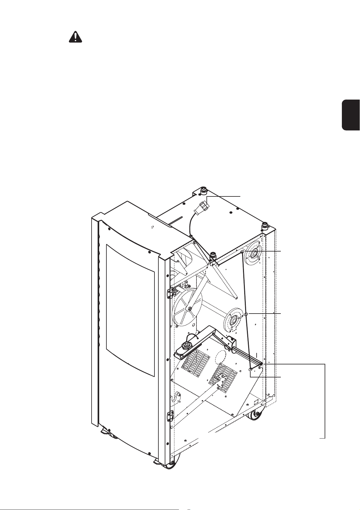
6-poliger Amphenolstecker
KabelBefestigungen:
Kabelbinder in
Bohrungen
einclipsen
KabelBefestigung
KabelBefestigung
(K)
KabelBefestigung
Kabelführungsrohr (K) muß die Seitenwand
durchdringen, an der die seitliche Blindabdekkung montiert ist.
Zusätzliche Details zur Montage, der Abbildung
auf der nächsten Seite entnehmen.
33
Page 4

Drahtendekontrolle montieren
(Fortsetzung)
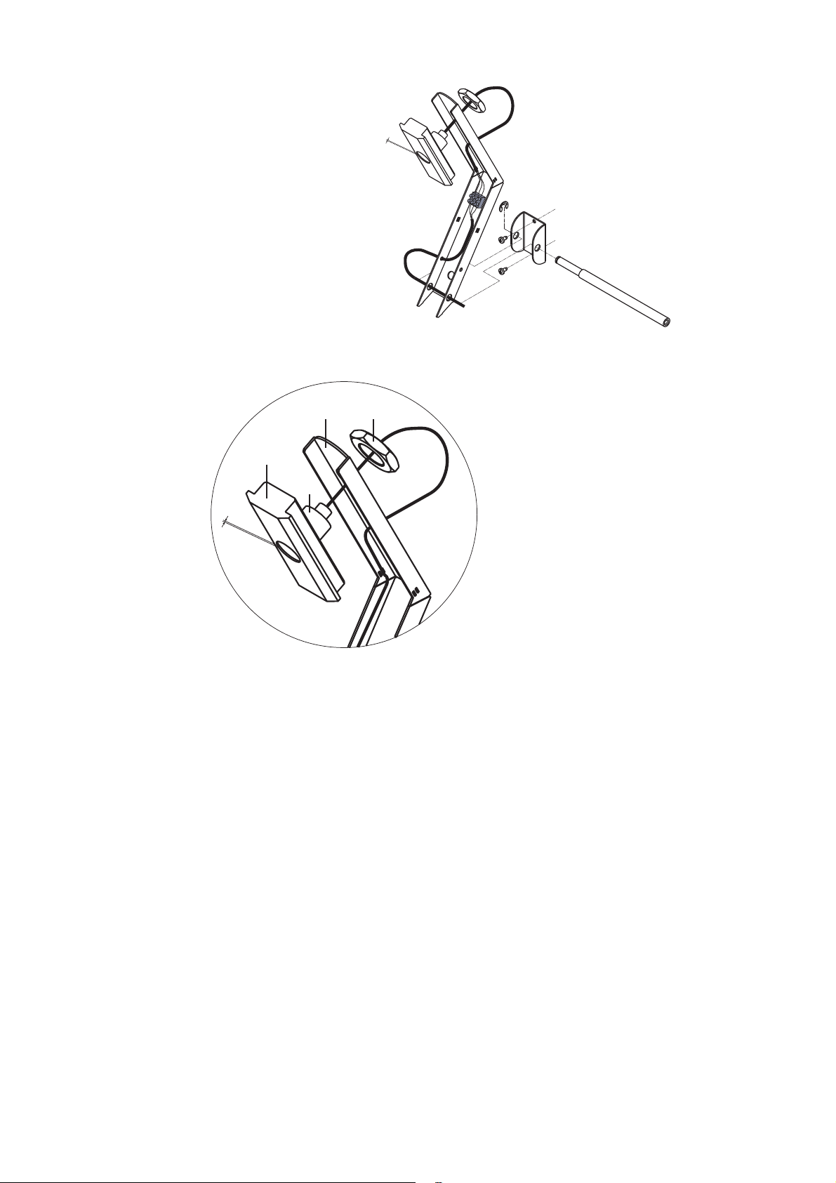
2 mm
Gleitschuh Wartung und
Inspektion
(48) (51)
(50)
(49)
2 mm
Einstellung
Hinweis! Ist ein Nachjustieren im nachfol-
gend beschriebenen Ausmaß nicht mehr
möglich, den Gleitschuh auswechseln
(Kapitel „Austausch“).
- Sechskantmutter (51) lösen
- Gleitschuh (50) mit Sensor (49) vom
Haltearm (48) abnehmen
Hinweis! Beim Abschrauben des Sensors
darauf achten, daß das Kabel nicht
verdrillt wird.
- Gleitschuh (50) vom Sensor (49)
abschrauben
- So daß der Abstand zwischen
Gleitfläche des Gleitschuhs (50)
und Oberfläche des Sensors (49)
2mm beträgt
- Gleitschuh (50) mit Sensor in den
Haltearm einsetzen
- Sechskantmutter (51) festschrauben
Kontrollintervall
Bei jedem fünften Drahtspulenwechsel
Kontrolle
- Haltearm (48) des induktiven Sensors
(49) hochschwenken
- Mittels Schiebelehre Abstand zwischen Gleitfläche des Gleitschuhs (50)
und Oberfläche des induktiven Sensors (49) messen
- Ist der Abstand kleiner als 0,5 mm,
Gleitschuh (50) einstellen (nachfolgendes Kapitel „Einstellung“)
- Haltearm (48) des induktiven Sensors
(49) abwärtsschwenken
Austausch
- Sechskantmutter (51) lösen
- Gleitschuh (50) mit Sensor (49) vom
Haltearm (48) abnehmen
Hinweis! Beim Abschrauben des Sensors
darauf achten, daß das Kabel nicht
verdrillt wird.
- Gleitschuh (50) vom Sensor (49)
abschrauben
- Neuen Gleitschuh auf den Sensor
schrauben
- So daß der Abstand zwischen
Gleitfläche des Gleitschuhs (50)
und Oberfläche des Sensors (49)
2mm beträgt
- Sechskantmutter (51) festschrauben
44
Page 5

Safety
Attention! This modification may only be performed by suitably trained and skilled
electricians! Follow the safety rules given in the Operating Instructions of the unreeling
device!
General remarks
Mounting the
end-of-wire
watchdog
The optional end-of-wire watchdog alerts the operator in good time to the fact that the
wire spool will soon need changing. This makes it possible to prevent unnecessary
disruption of the production process.
The end-of-wire watchdog is based on the principle of an inductive sensor that
constantly samples the wire spool.
Before the final layer has been completely unreeled, the system ceases to detect any
more wire - and the inductivity of the sensor changes.
This property can be exploited by a suitable electronic circuit and outputted as an endof-wire alarm.
6-pole Amphenol plug
Cable fasteners:
Clip the cable
binders into the
drilled holes
Cable fastener
EN
Cable fastener
(K)
Cable fastener
Cable-guide tube (K) must pass through the
sidewall that the side blanking cover is mounted to.
For more details on mounting the end-of-wire
watchdog, please see the illustration on the
next page.
55
Page 6

Mounting the
end-of-wire
watchdog
(continued)
2 mm
Shoe - Maintenance and Inspection
(48) (51)
(50)
(49)
2 mm
Adjusting the shoe
N.B.! If it is no longer possible to adjust the
shoe to the extent described below, change
the shoe (see “Changing the shoe”).
Inspection interval
Every 5th time the wire spool is changed
Inspection procedure
- Tilt up the carrier arm (48) of the
inductive sensor (49)
- Use a sliding gauge to measure the gap
between the slide-face of the shoe (50)
and the surface of the inductive sensor
(49):
- if this gap is less than 0.5 mm, adjust
the shoe (50) (see “Adjusting the
shoe” below)
- Tilt down the carrier arm (48) of the
inductive sensor (49)
Changing the shoe
- Undo the hexagon nut (51)
- Detach the shoe (50), complete with the
sensor (49), from the carrier arm (48)
- Undo the hexagonal nut (51)
- Detach the shoe (50), complete with the
sensor (49), from the carrier arm (48)
N.B.! When unscrewing the sensor, take
care that the cable does not get twisted.
- Unscrew the shoe (50) from the sensor
(49):
- in such a way that the gap between
the slide-face of the shoe (50) and
the surface of the sensor (49) is 2 mm
- Insert the shoe”(50)”, complete with the
sensor, into the carrier arm
- Tighten the hexagon nut (51)
66
N.B.! When unscrewing the sensor, take
care that the cable does not get twisted.
- Unscrew the shoe (50) from the sensor
(49)
- Screw the new shoe onto the sensor:
- in such a way that the gap between
the slide-face of the shoe (50) and
the surface of the sensor (49) is 2 mm
- Tighten the hexagon nut (51)
Page 7
Sécurité
Attention ! Seuls les agents spécialisés et formés sont autorisés à effectuer cette
transformation ! Conformez-vous aux consignes de sécurité indiquées dans le mode
d’emploi du dévidoir !
Généralités
Monter le contrôle de fin de fil
Le contrôle de fin de fil disponible en option vous signale suffisamment tôt qu’il faut
changer la bobine de fil. Cela permet d’éviter les interruptions inutiles du processus de
production.
Le contrôle de fin de fil se base sur le principe d’une sonde inductive qui palpe
constamment la bobine.
Le fil n’est plus enregistré avant la fin du déroulement de la dernière couche.
L’inductivité de la sonde change.
Cette caractéristique peut être évaluée par un commutateur électronique approprié et
être sortie comme alarme de fin de fil.
Connecteuer Amphenol 6 pôles
Fixations du
câble: fixer les
attache-câbles
dans les trous
Fixation du câble
FR
Fixation du câble
(K)
Fixation du
câble
Le tube guide-câble (K) doit traverser la
paroi latérale sur laquelle est monté le faux
couvercle latéral.
Vous trouverez de plus amples détails concernant le montage sur le dessin de la page
suivante.
77
Page 8
Monter le contrôle de fin de fil
(suit)
2 mm
Patin - Maintenance et Inspection
(48) (51)
(50)
(49)
2 mm
Réglage
Remarque ! S’il n’est plus possible de
faire de réajustage sur la base des dimensions indiquées ci-après, changer le patin
(chapitre « Remplacement »).
- Dévisser l’écrou hexagonal (51)
- Enlever le patin (50) du bras de maintien (48), avec la sonde (49)
Remarque ! Lorsque vous dévissez la
sonde, veillez à ce que le câble ne soit pas
tordu.
- Dévisser le patin (50) de la sonde (49)
- de manière à ce que la distance entre
la surface de glissement du patin
(50) et la surface de la sonde (49)
fasse 2 mm
- Placer le patin (50) dans le bras de
maintien, avec la sonde
- Visser l’écrou hexagonal (51)
Intervalles de contrôle
Tous les cinq changements de bobine de
fil
Contrôle
- Relever le bras de maintien(48) de la
sonde inductive(49)
- Mesurer la distance entre la surface de
glissement du patin (50) et la surface de
la sonde inductive (49) avec un pied à
coulisse
- Si la distance est inférieure à 0,5 mm,
ajuster le patin (50) (chapitre ci-après
« Réglage »)
- Descendre le bras de maintien (48) de
la sonde inductive (49)
Remplacement
- Dévisser l’écrou hexagonal (51)
- Enlever le patin (50) du bras de maintien (48), avec la sonde (49)
Remarque ! Lorsque vous dévissez la
sonde, veillez à ce que le câble ne soit pas
tordu.
- Dévisser le patin (50) de la sonde (49)
- Visser un nouveau patin sur la sonde
- de manière à ce que la distance entre
la surface de glissement du patin
(50) et la surface de la sonde (49)
fasse 2 mm
- Visser l’écrou hexagonal (51)
88
Page 9

43,0002,0384
42,0100,0475
41,0009,0060
42,0407,0341
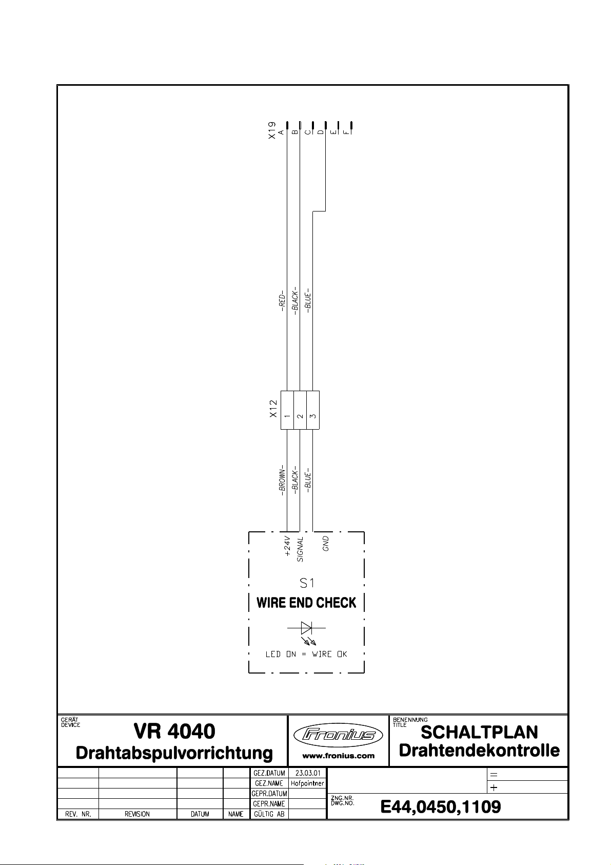
WIRE-END CONTROL VR 4040 44,0450,1109
Ersatzteilliste / Spare parts list / Listes de pièces de rechange / Lista de repuestos / Lista de pecas sobresselentes / Lista dei Ricambi
el_fr_st_so_00438 012001
1/1
Page 10
Page 11

FRONIUS INTERNATIONAL GMBH
Froniusplatz 1, A-4600 Wels, Austria
Tel: +43 (0)7242 241-0, Fax: +43 (0)7242 241-3940
E-Mail: sales@fronius.com
www.fronius.com
Under http://www.fronius.com/addresses you will find all addresses
www.fronius.com/addresses
of our Sales & service partners and Locations.
ud_fr_st_so_00082 012011
 Loading...