

Page 1

APPLICATION GUIDE
EMERGENCY BACKSTOP MECHANISM
– DRM SETUP WITH TMAC GSD
THIS DOCUMENT AIMS TO PROVIDE EASY-TO-FOLLOW INSTRUCTIONS ON HOW TO INSTALL
A GSD WITH A FRONIUS SNAP AND GEN24 INVERTER
Application Guide
© Fronius Australia Pty Ltd.
Version 1.0/2023
Fronius reserves all rights, in particular rights of reproduction, distribution and translation.
No part of this work may be reproduced in any way without the written consent of Fronius. It must not be saved,
edited, reproduced or distributed using any electrical or electronic system.
You are hereby reminded that the information published in this document, despite exercising the greatest of care
in its preparation, is subject to change and that neither the author nor Fronius can accept any legal liability
Gender-specific wording refers equally to female and male form.
(c) Fronius Australia Pty. Ltd, 2023 1/16
Page 2

GSD installed
10kVA
10kVA
replacement
inverters
Not required for warranty ‘like for like’ replacement
Not required for warranty ‘like for like’ replacement
inverters
Not required for warranty ‘like for like’ replacement
voltage
supply)
– warranty replacement
voltage
1. CHANGE LOG
Date Version Comments Author
05/01/23 1.0 Initial release Fronius Australia
2. GENERAL
The emergency backstop mechanism is a system designed to curtail rooftop PV generation by remote
command from the utility. This control allows the utility to maintain stability of the grid in events where
the grid is under stress from high rooftop PV.
The system will be implemented by installing an external device called a Generation Signalling Device
(GSD) which will be capable of communicating with the utility and the onsite solar generation for
curtailment. The utility communication is being done through the Audio Frequency Load Control
(AFLC) system which done over the power lines. The inverter communication is done through
Demand Response Mode (DRM) ports which allow the inverter to receive control signals to ramp
power up/down and switch off/on remotely.
This mechanism is being mandated in particular IES connections and will be enforced in Queensland
as of the 6th of February 2023.
3. SITE REQUIREMENTS
There are multiple factors outlined by Ergon Energy/Energex to determine whether a GSD is required
as part of the installation. Below are the current IES connections that must install a device (as seen at
the time of publishing this document).
Connection
Category
Low
voltage
Low
voltage
Low
voltage
Low
voltage
Low
voltage
Low
voltage
Low
High
Some areas are also not serviced by the AFLC system so please check the NMI in the search
function found on Ergon Energy/Energex’s website.
For the most current information regarding requirements for the Emergency Backstop Mechanism
please visit Ergon Energy / Energex’s website:
Ergon: https://www.energex.com.au/home/our-services/connections/low-voltage-
generation/emergency-backstop-mechanism
Total
Inverter
Capacity
Less
than
Less
than
10kVA
Less
than
10kVA
or higher
10kVA
or higher
10kVA
or higher
Any
Any Any No N/A N/A
Types of Inverter Connections Required
Initial connection No N/A N/A
Increase inverter capacity No N/A N/A
Replace inverter (no increase of
supply) – not a warranty
Initial connection
Increase inverter capacity
Replace inverter (no increase of
supply) – not a warranty
replacement
Replace inverter (no increase of
to Install
a GSD
No N/A N/A
Yes
Including
hybrid
Yes
Including
hybrid
inverters
Yes
Including
hybrid
No N/A N/A
Exclusions Requirement for
Not required where inverter solely supplied by
energy storage system (AC coupled batteries)
Not required in non AFLC areas
Not required where
inverter solely supplied by energy storage system
(AC coupled batteries)
Not required in non AFLC areas
Not required where inverter solely supplied by
energy storage system (AC coupled batteries)
Not required in non AFLC areas
Inverters to be GSD
capable and have
All inverters
All new inverters only
All new inverters only
(c) Fronius Australia Pty. Ltd, 2023 2/16
Page 3

Energex: https://www.ergon.com.au/network/connections/low-voltage-generation/emergency-
backstop-mechanism
4. TECHNICAL INFORMATION AND SETUP
Once the IES connection has been assessed and a GSD is required, the next step is installing the
GSD with the Fronius inverter. All current Fronius inverters (Fronius Snap and GEN24/Tauro) are
capable of demand response management hence are compatible with GSD’s. Please see below
setup information, note that the process is different between the Snap and GEN24/Tauro,
4.1 Generation Signalling Device
Currenlty approved GSD’s:
https://www.energex.com.au/__data/assets/pdf_file/0020/1035623/Approved-Generation-SignallingDevices.pdf
Currently there is only one approved GSD which is from TMAC, the cost is listed to be ~$70 for the
device.
TMAC Install Manual: https://www.tmacgroup.com.au/wp-content/uploads/2022/10/TM-UI-036-GSD-
Installer-Manual.pdf
Figure 4.1: GSD and RJ45 adaptor:
Image source: https://www.tmacgroup.com.au/product/generation-signalling-device-gsd-aflc/
4.2 Installing a GSD with a Fronius SnapINverter
4.2.1 Equipment:
1. Laptop/smart device
For every Solar Net Loop/Master Datamanager card
1. 1x GSD
2. 1x DRM Interface Card
3. 1x Datamanager Card
4.2.2 Steps Overview
1. Commission Inverter
2. Connect DRM Interface Card to inverter
3. Set I/O Mapping
4. Connect GSD to DRM interface Card
Figure 4.2: Fronius SnapINverter
(c) Fronius Australia Pty. Ltd, 2023 3/16
Page 4

DRM Interface card (RIGHT)
Step 1. Commission Inverter:
The inverter is to be commissioned prior to the next GSD install steps. After commissioning is
complete, please proceed to the next step. This document does not cover setup and commissioning
and assumes that you are aware of how to do this, please visit our website for resources on how to do
this.
Step 2. Install DRM Interface Card:
Important Notes:
The DRM interface card is an optional extra that must be purchased and retrofitted to the
inverter.
This is only required on SnapINverters not GEN24/Tauro.
The DRM interface card can only be installed on inverters that contain a datamanager card.
That datamanager must also be operating as a master.
You only require one GSD and DRM Interface card per Solar Net loop/Master datamanager
card.
Below displays what the DRM interface Card looks like when installed. When the card is purchased, it
will also come with a pre-wired orange terminal block (to connect to the datamanager card as seen
below), 1x screw, instructions and a sticker.
Figure 4.3: Datamanager card (LEFT)
How to install the DRM Interface Card:
Figure 4.4: Remove Cable Cover
(c) Fronius Australia Pty. Ltd, 2023 4/16
Page 5

Figure 4.5: Remove screw and terminal block, insert DRM interface card
Figure 4.6: Insert new screw and pre wired terminal block. Place sticker.
Figure 4.7: Take note of the REF GEN/0 and COM LOAD/0 port on the card. These will be used in the GSD
setup.
(c) Fronius Australia Pty. Ltd, 2023 5/16
Page 6

Step 3. Set I/O Mapping:
The I/O settings can be adjusted via the Datamanager website (webserver is built-in) by following
these steps:
1. Activate the Wi-Fi hotspot on the Datamanager card (inverter) or Datamanager Box V2
2. Connect your computer/tablet/smartphone to the Datamanager’s WLAN hotspot*. Or connect
a LAN cable to the computer.
3. Open a web browser and go to http://192.168.250.181
Once the local server is open, you will see the server displayed as below:
Figure 4.8: Local Server of SnapINverter
4. Press on the Settings button to get to the next page
Figure 4.9: Login Page
5. Login as a “service” user to obtain access to the required settings.
(c) Fronius Australia Pty. Ltd, 2023 6/16
Page 7
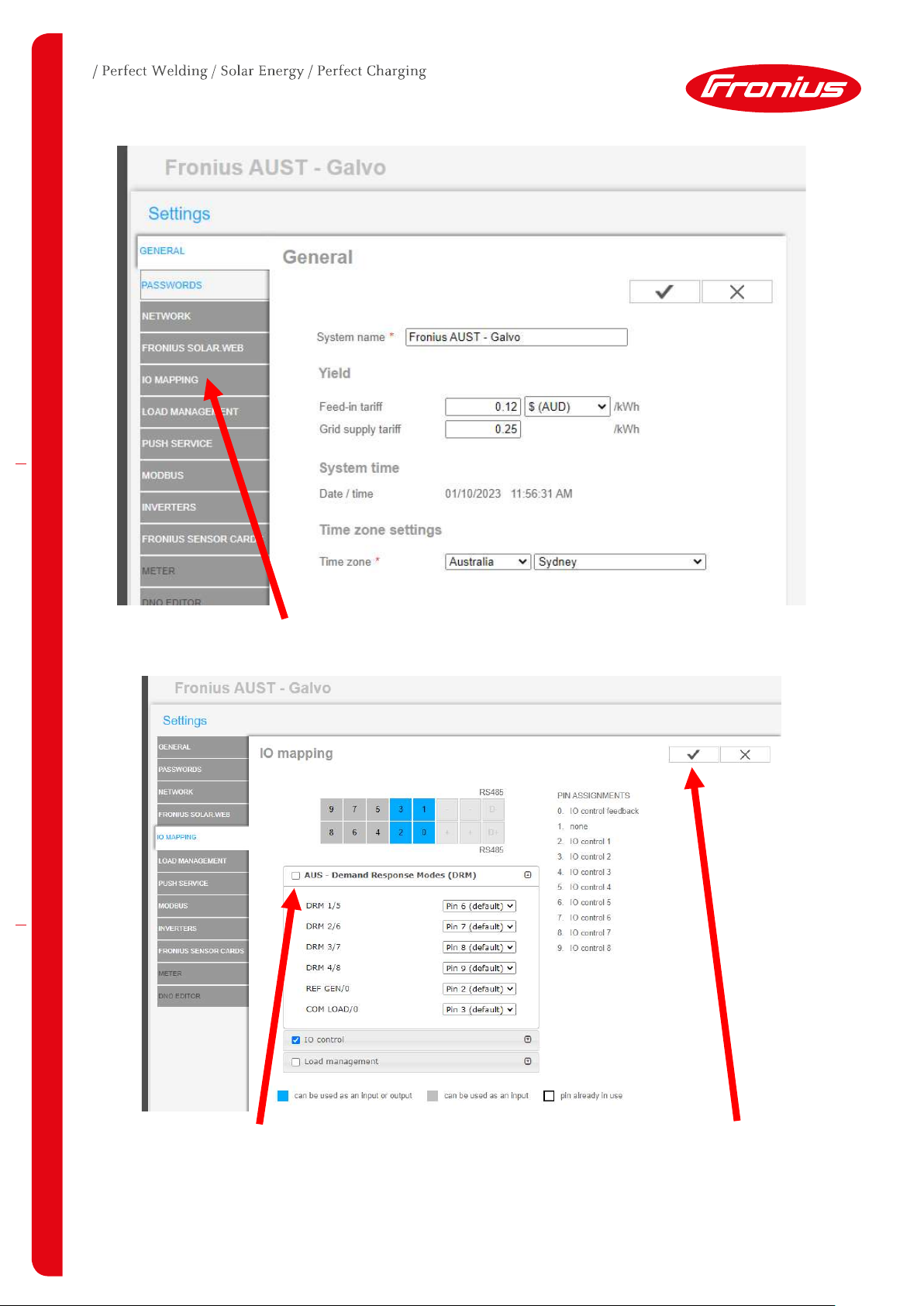
Figure 4.10: Settings page
6. Click on I/O Mapping to proceed
Figure 4.11: I/O Mapping Setup
7. Click the tickbox for “AUS – Demand Response Modes (DRM)”. Then click on the tick to save
the settings.
(c) Fronius Australia Pty. Ltd, 2023 7/16
Page 8

This will automatically allocate the DRM pins to the I/O on the orange terminal block of the inverter.
Step 4. Setup the Control priorities of the inverter:
Figure 4.12: DNO Editor
1. Click on DNO Editor
Figure 4.13: Control Priorities
2. Click on the arrows to shift IO control to the highest priority level. Then click the tick to save.
In all circumstances when using DRM control, the IO control must be the highest priority. If export
control is being used, this can be the second priority.
(c) Fronius Australia Pty. Ltd, 2023 8/16
Page 9

Figure 4.
16
: Fronius
GEN24
Inverter
Step 5. Connect GSD to DRM interface Card:
Now that the Inverter is commissioned, DRM Interface has been installed and the DRM has been
activated the GSD can be installed.
1. Connect the RJ45 adaptor to the RJ45 on the TMAC GSD
2. Connect YELLOW wire to RG/0
3. Connect GREY wire to CL/0
Figure 4.15: TMAC Wiring Diagram:
https://www.tmacgroup.com.au/wpcontent/uploads/2022/10/TM-UI-036-GSD-Installer-Manual.pdf
Figure 4.14: Where to connect GSD to
DRM Interface
Congratulations - Now all SnapINverters connected in the existing Solarnet loop can be controlled via
the GSD device and the Emergency Backstop Mechanism installation with the Fronius inverter is
complete. If there are any separate SnapINverters not connected in the same Solarnet loop they will
require a separate GSD.
4.3 Installing a GSD with a Fronius GEN24 Inverter
4.3.1 Equipment
1. Laptop/smart device
2. 1x GSD per Inverter
4.3.2 Steps Overview
1. Commission Inverter
2. Set I/O Mapping
3. Connect GSD to DRM ports
Step 1. Commission Inverter:
The inverter is to be commissioned prior to the next GSD install steps. After commissioning is
complete, please proceed to the next step. This document does not cover setup and commissioning
and assumes that you are aware of how to do this, please visit our website for resources on how to do
this.
(c) Fronius Australia Pty. Ltd, 2023 9/16
Page 10

Step 2. Set I/O Mapping:
The I/O settings can be adjusted via the inverter’s local server (webserver is built-in) by following
these steps with a smart device.
1. Please connect the inverter to your smart device either via Ethernet or Wi-Fi, see steps for
either connection below.
Figure 4.17: WLAN Connection process
1. Open the access point by touching the sensor once → Communication LED should now flash
blue.
2. Establish the connection to the inverter in the network settings (the inverter is displayed with the
name "FRONIUS_PILOT" and the serial number of the device).
3. Password: enter 12345678 and confirm.
IMPORTANT!
To enter the password on a Windows 10 operating system, the link "Connect using a security key
instead" must first be activated to establish a connection with the password: 12345678.
4. In the browser address bar, enter and confirm the IP address 192.168.250.181. The local server
should now be displayed.
Figure 4.18: Ethernet Connection Process
1. Establish a connection to the inverter (LAN1) with a network cable (CAT5 STP or higher).
2. Open the access point by touching the sensor once → Communication LED: flashes blue.
3. In the browser address bar, enter and confirm IP address 169.254.0.180. The installation wizard
is opened
(c) Fronius Australia Pty. Ltd, 2023 10/16
Page 11

Once the local server is open, you will see the server displayed as below:
Figure 4.19: Local Sever of GEN24
2. Press on the Login button and login as a Technician.
Figure 4.20: Technician Page
3. Once Logged in as a Technician click on “Device Configuration” to proceed to the next page.
Figure 4.21: Functions and I/O's
4. From The Device configuration page click on “Functions and I/Os”
(c) Fronius Australia Pty. Ltd, 2023 11/16
Page 12

5. Click on the toggle switch to turn Australia – Demand Response Modes (DRM) to ON.
Figure 4.22: DRM Page
6. Click the Save button to save this setting.
If the site has “Full Backup” or any I/O pins are being used for other purposes there may be some pin
clashes. Please see the next steps to resolve this, otherwise skip to (10.).
7. If Full Backup is activated, please note that Pin 6 and Pin 7 will clash as per the below notice.
Figure 4.23: Full Backup Clash
(c) Fronius Australia Pty. Ltd, 2023 12/16
Page 13

8. In the event of this happening please change DRM 1/5 and DRM 2/6 to Pin 10 and Pin 11
respectively to prevent the clash from occurring. Then click the save button to save the
changes.
Figure 4.24: Pin re-assignment
9. If a clash is still present you will be required to alter the pin layout to avoid these clashes.
Further steps in this material will be using the default pins for REF GEN/0 and COM LOAD/0. If DRM
connections other than these are changed/moved this will not affect GSD connection points or any
installation requirements for the Emergency Backstop Mechanism.
If either or both REF GEN/0 and COM LOAD/0 pins need to be changed from default, please note the
pin assignment to ensure the correct pins are used in subsequent steps.
Figure 4.25: Back to Device Configuration
10. Click on “Device Configuration” to return to the main menu.
(c) Fronius Australia Pty. Ltd, 2023 13/16
Page 14

Figure 4.26: Safety and Grid Regulations
11. Click on “Safety and Grid Regulations”
Figure 4.27: I/O Power Management Menu
12. Click on “I/O Power Management” and alter the Control Priorities (click and drag) to ensure
that IO Power limit is the top priority (1.).
Now the DRM I/O’s are activated and ready for use with the GSD.
(c) Fronius Australia Pty. Ltd, 2023 14/16
Page 15

Step 4. Connect GSD to DRM interface Card:
Now that the Inverter is commissioned, and the DRM has been activated the GSD can be installed.
Locate the data communication board within the inverter. Find the I/O terminal block.
Figure 4.28: Data Communication Board
1. Connect RJ45 adapter with RJ45 connector on GSD
2. Connect YELLOW wire to IO4
3. Connect GREY wire to IO5
Figure 4.29: Wiring TMAC to IO board: https://www.tmacgroup.com.au/wp-
content/uploads/2022/10/TM-UI-036-GSD-Installer-Manual.pdf
Congratulations - Now your GEN24 inverter is connected and can be controlled via the GSD device
and the Emergency Backstop Mechanism installation with the Fronius inverter is complete. Keep in
mind that if there are multiple GEN24’s onsite this process must be repeated for each inverter.
(c) Fronius Australia Pty. Ltd, 2023 15/16
Page 16

END OF DOCUMENT
Fronius Australia Technical Support
Email: PV-Support-Australia@fronius.com
Phone: 03 8340 2910
For more detailed information see the operation manual available on the product specific page on http://www.fronius.com/en-
au/australia
(c) Fronius Australia Pty. Ltd, 2023 16/16
 Loading...