

Page 1

Fronius prints on elemental chlorine free paper (ECF) sourced from certified sustainable forests (FSC).
/ Perfect Charging / Perfect Welding / Solar Energy
Umbau-Set CU 1800 Interface FC
Umbau-Set CU 4700 Interface FC
CU 1800 Interface FC Conversation
Kit
CU 4700 Interface FC Conversation
Kit
Installationsanleitung
DEEN-US
Kühlgerät
Installation Instructions
Cooling unit
42,0410,2476 004-04032020
Page 2

2
Page 3

Inhaltsverzeichnis
Allgemeines ............................................................................................................................................... 5
Sicherheit.............................................................................................................................................. 5
Lieferumfang......................................................................................................................................... 6
Erforderliche Werkzeuge ...................................................................................................................... 6
Hinweise für den Betrieb....................................................................................................................... 6
Umbau-Set CU 1800 / 4700 Interface FC einbauen .................................................................................. 7
Umbau-Set CU 1800 / 4700 Interface FC einbauen............................................................................. 7
Einstellungen am Kühlgerät ....................................................................................................................... 9
Allgemeines .......................................................................................................................................... 9
Notwendige Einstellungen für die Kommunikation zwischen Stromquelle und Kühlgerät .................... 9
Optionale Einstellungen für Durchfluss-Sensoren ................................................................................ 9
DE
3
Page 4

4
Page 5

Allgemeines
DE
Sicherheit
WARNUNG!
Gefahr durch Fehlbedienung und fehlerhaft durchgeführte Arbeiten.
Schwerwiegende Personen- und Sachschäden können die Folge sein.
► Alle in diesem Dokument beschriebenen Arbeiten und Funktionen dürfen nur von Fro-
nius-geschultem Servicepersonal ausgeführt werden.
► Dieses Dokument lesen und verstehen.
► Sämtliche Bedienungsanleitungen der Systemkomponenten, insbesondere Sicher-
heitsvorschriften lesen und verstehen.
WARNUNG!
Gefahr durch elektrischen Strom.
Schwere Verletzungen oder Tod können die Folge sein.
► Vor Beginn der Arbeiten alle beteiligten Geräte und Komponenten ausschalten und
von Stromnetz trennen.
► Alle beteiligten Geräte und Komponenten gegen Wiedereinschalten sichern.
► Nach dem Öffnen des Gerätes mit Hilfe eines geeigneten Messgerätes sicherstellen,
dass elektrisch geladene Bauteile (beispielsweise Kondensatoren) entladen sind.
WARNUNG!
Gefahr durch elektrischen Strom wegen unzureichender Schutzleiter-Verbindung.
Schwerwiegende Personen- und Sachschäden können die Folge sein.
► Immer die originalen Gehäuse-Schrauben in der ursprünglichen Anzahl verwenden.
VORSICHT!
Gefahr durch heiße Systemkomponenten und heißes Kühlmittel.
Schwere Verbrühungen können die Folge sein.
► Alle nachfolgend beschriebenen Arbeiten nur durchführen, wenn das Kühlmittel auf
Zimmertemeratur abgekühlt ist (+25 °C, +77 °F).
► Alle nachfolgend beschriebenen Arbeiten nur durchführen, wenn die Systemkompo-
nenten auf Zimmertemeratur abgekühlt sind (+25 °C, +77 °F).
VORSICHT!
Risiko durch Kühlmittel-Austritt.
Schwerwiegende Sachschäden können die Folge sein.
► Wenn Kühlmittel an die Außenseite des Kühlgerätes gelangt, dieses sofort entfernen.
► Sicherstellen, dass kein Kühlmittel in den Geräteinnenraum gelangt.
5
Page 6

Lieferumfang
ROB 3000
Interface FC
ROB 3000
Interface FC
Umbau-Set CU 1800 Interface FC Umbau-Set CU 4700 Interface FC
ohne Abbildung:
- Montage-Set ROB 3000
- 2 Innensechskant-Schrauben SW 2 mm
- 2 Fächerscheiben
- Bedienungsanleitung ROB 3000
- diese Installationsanleitung
Erforderliche
Werkzeuge
Hinweise für den
Betrieb
- Innensechskant-Schlüssel SW 2 mm
- Kreuz-Schraubendreher
Das Interface FC kann nur in Verbindung mit Stromquellen der digitalen Geräteserie betrieben werden:
- TPS 2700 - 5000
- TransTig 3000 - 5000
- MagicWave 3000 - 5000
Das Interface FC kann nicht mit TPSi-Stromquellen betrieben werden.
6
Page 7

Umbau-Set CU 1800 / 4700 Interface FC einbauen
1
1
1
2
2
3
3
DE
Umbau-Set CU
1800 / 4700 Interface FC einbauen
Die Montage des Interface FC wird am Beispiel des Kühlgerätes CU 1800 beschrieben.
Die Montage am Kühlgerät CU 4700 erfolgt analog dazu.
2 Kreuzschrauben an der GeräteRückseite entfernen
Die beiden Schrauben werden in späterer
Folge zur Montage des Interface FC benötigt.
9-poligen D-Sub Stecker vom Interface FC am Gerät anstecken
12-poligen Stecker vom Interface FC
am Gerät anstecken
7
Page 8

D-Sub Stecker mit den 2 Innensechs-
4
2x
4
5
5
5
*
6
6
6
kant-Schrauben SW 2 mm aus dem
Lieferumfang fixieren
Die zuvor von der Geräte-Rückseite
entfernten Kreuzschrauben mit den
Fächerscheiben aus dem Lieferumfang bestücken
Interface FC mit den Kreuzschrauben
und den Fächerscheiben an der Geräte-Rückseite fixieren
* Beim Kühlgerät CU 4700 befindet
sich das Netzkabel neben dem Interface FC.
8
Page 9
Einstellungen am Kühlgerät
2
3
6
Allgemeines Nähere Informationen zu den Einstellmöglichkeiten am Kühlgerät der Bedienungsanlei-
tung des Kühlgerätes entnehmen.
DE
Notwendige Einstellungen für die
Kommunikation
zwischen Stromquelle und Kühlgerät
Kabel vom Umbau-Set CU Interface FC an der Stromquelle anschließen
1
Die nachfolgenden Einstellungen am Kühlgerät vornehmen.
Kommunikationsmodus festlegen:
4x Taste MENU für 2 Sekunden drücken, um in das Kommunikationsmenü zu gelangen
- die nachfolgende Anzeige erscheint
Mittels Pfeiltasten die Einstellung auswählen
Taste SEL drücken
4
- die Einstellung wird bestätigt
Kontakteingangssignal 1 festlegen:
Taste SEL so oft drücken, bis die nachfolgende Anzeige erscheint
5
Optionale Einstellungen für Durchfluss-Sensoren
Mittels Pfeiltasten die Einstellung auswählen
Taste SEL drücken
7
- die Einstellung wird bestätigt
Falls das Kühlgerät mit Durchfluss-Sensoren betrieben wird, die im nachfolgenden
8
Abschnitt Optionale Einstellungen für Durchfluss-Sensoren beschriebenen Einstellungen vornehmen
Kontakteingangssignal 2 festlegen:
Taste SEL so oft drücken, bis die nachfolgende Anzeige erscheint
1
Mittels Pfeiltasten die Einstellung auswählen
2
Taste SEL drücken
3
- die Einstellung wird bestätigt
9
Page 10

Signaltyp einstellen:
5
8
12
Taste SEL so oft drücken, bis die nachfolgende Anzeige erscheint
4
Mittels Pfeiltasten die Einstellung auswählen
Taste SEL drücken
6
- die Einstellung wird bestätigt
Verzögerungszeit für das Lesen des Kontakteingangssignal 2 einstellen:
Taste SEL so oft drücken, bis die nachfolgende Anzeige erscheint
7
Mittels Pfeiltasten einen Wert von 0 - 300 (Sekunden) einstellen
Taste SEL drücken
9
- die Einstellung wird bestätigt
Kontaktausgangssignal 3 festlegen:
Taste SEL so oft drücken, bis die nachfolgende Anzeige erscheint
10
Mittels Pfeiltasten die Einstellung auswählen
11
Taste SEL drücken
- die Einstellung wird bestätigt
10
Page 11

Table of contents
General ...................................................................................................................................................... 13
Safety.................................................................................................................................................... 13
Scope of Supply.................................................................................................................................... 14
Tools Required...................................................................................................................................... 14
Notes for the Operation......................................................................................................................... 14
Installing the CU 1800 / 4700 Interface FC Conversation Kit .................................................................... 15
Installing the CU 1800 / 4700 Interface FC Conversation Kit ............................................................... 15
Settings on the Cooling Unit ...................................................................................................................... 17
General ................................................................................................................................................. 17
Required Settings for Communication Between the Power Source and Cooling Unit.......................... 17
Optional Settings for Flow Sensors....................................................................................................... 17
EN-US
11
Page 12

12
Page 13

General
Safety
WARNING!
Danger from incorrect operation and work that is not carried out properly.
Serious personal injury and damage to property may result.
► All the work and functions described in this document must only be carried out by a
trained Fronius service technician.
► Read and understand this document.
► Read and understand all the system component Operating Instructions, especially the
safety rules.
WARNING!
Danger from electrical current.
Serious injuries or death may result.
► Before starting work, switch off all devices and components involved, and disconnect
them from the grid.
► Secure all devices and components involved so they cannot be switched back on.
► After opening the device, use a suitable measuring instrument to check that electrically
charged components (such as capacitors) have been discharged.
WARNING!
EN-US
Danger from electrical current due to inadequate ground conductor connection.
Serious personal injury and damage to property may result.
► Always use the original housing screws in the quantity initially supplied.
CAUTION!
Danger due to hot system components and hot coolant.
Serious burns may result.
► Only perform all work described below when the coolant has cooled down to room tem-
perature (+25 °C, +77 °F).
► Only perform all work described below when the system components have cooled
down to room temperature (+25 °C, +77 °F).
CAUTION!
Risk of coolant escaping.
Serious damage to property may result.
► If coolant ends up on the outside of the cooling unit, this should be removed immedi-
ately.
► Make sure that no coolant ends up inside the machine.
13
Page 14
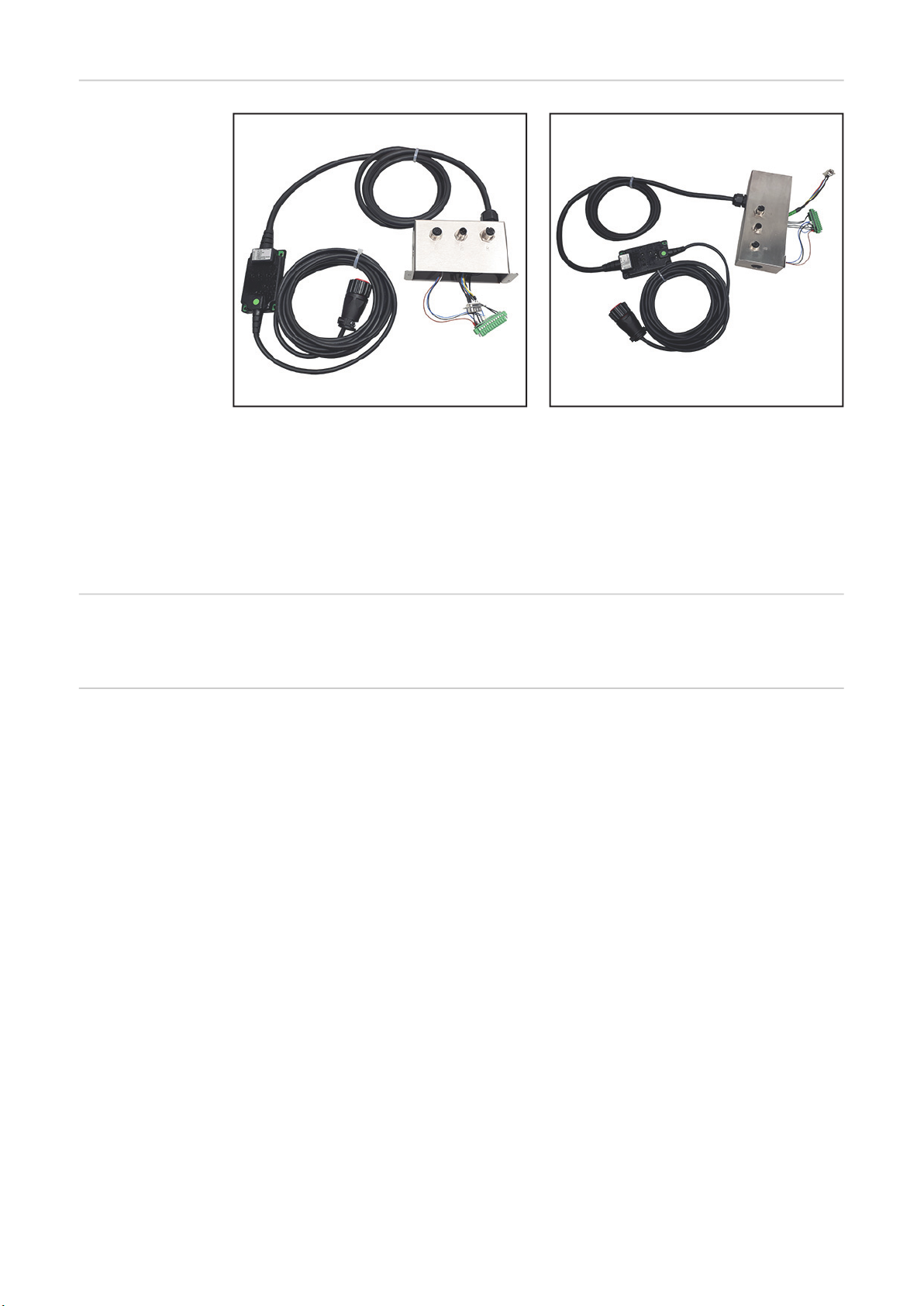
Scope of Supply
ROB 3000
Interface FC
ROB 3000
Interface FC
CU 1800 Interface FC conversation kit CU 4700 Interface FC conversation kit
Not shown:
- ROB 3000 installation set
- 2 Allen screws size 2 mm
- 2 serrated lock washers
- ROB 3000 Operating Instructions
- This set of Installation Instructions
Tools Required - Allen key size 2 mm
- Phillips screwdriver
Notes for the Operation
The interface FC can only be operated in connection with power sources of the digital device series:
- TPS 2700 - 5000
- TransTig 3000 - 5000
- MagicWave 3000 - 5000
The interface FC can not be operated with TPSi power sources.
14
Page 15

Installing the CU 1800 / 4700 Interface FC Conversa-
1
1
1
2
233
tion Kit
Installing the CU
1800 / 4700 Interface FC Conversation Kit
In the example below, the FC interface is mounted to a CU 1800 cooling unit. The procedure is the same for the CU 4700 cooling unit.
Remove two Phillips screws from the
rear of the device
These two screws will be needed again later.
Connect the 9-pin D-Sub plug from the
FC interface to the device
EN-US
Connect the 12-pin plug from the FC
interface to the device
15
Page 16

Secure the D-Sub plug in position
4
2x
4
5
5
5
*
6
6
6
using the two Allen screws (2 mm)
from the scope of supply
Place the serrated lock washers from
the scope of supply onto the two
screws previously removed from the
rear of the device
Secure the FC interface to the rear of
the device using the Phillips screws
with the serrated lock washers
* On the CU 4700 cooling unit, the
power cable is next to the FC interface.
16
Page 17

Settings on the Cooling Unit
2
3
6
General For more detailed information regarding the settings on the cooling unit, see the cooling
unit Operating Instructions.
EN-US
Required Settings
for Communication Between the
Power Source
and Cooling Unit
Connect the cable from the CU Interface FC conversation kit to the power source
1
Apply the following settings on the cooling unit.
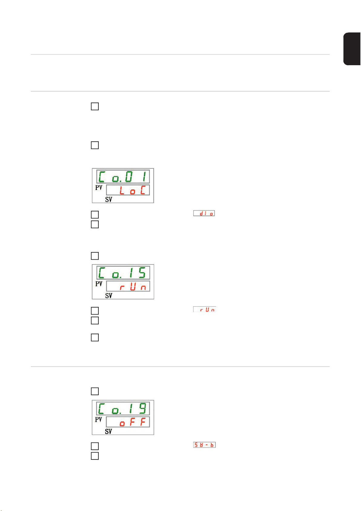
Define the communication mode:
Press the MENU key 4 times for 2 seconds to enter the communication menu
- The following display appears
Use the arrow keys to select the setting
Press the SEL key
4
- The setting is confirmed
Define contact input signal 1:
Press the SEL key until the following display appears
5
Optional Settings
for Flow Sensors
Use the arrow keys to select the setting
Press the SEL key
7
- The setting is confirmed
If the cooling unit is operated with flow sensors, apply the settings described in the fol-
8
lowing section Optional Settings for Flow Sensors
Define contact input signal 2:
Press the SEL key until the following display appears
1
Use the arrow keys to select the setting
2
Press the SEL key
3
- The setting is confirmed
17
Page 18

Set the signal type:
5
8
12
Press the SEL key until the following display appears
4
Use the arrow keys to select the setting
Press the SEL key
6
- The setting is confirmed
Set the delay time for reading contact input signal 2:
Press the SEL key until the following display appears
7
Set a value from 0 - 300 (seconds) using the arrow keys
Press the SEL key
9
- The setting is confirmed
Set the contact output signal 3:
Press the SEL key until the following display appears
10
Use the arrow keys to select the setting
11
Press the SEL key
- The setting is confirmed
18
Page 19

EN-US
19
Page 20

FRONIUS INTERNATIONAL GMBH
Froniusstraße 1, A-4643 Pettenbach, Austria
E-Mail: sales@fronius.com
www.fronius.com
Under www.fronius.com/contact you will find the addresses
of all Fronius Sales & Service Partners and locations
 Loading...