

Page 1

/ Perfect Charging / Perfect Welding / Solar Energy
Anschlussplatte
Connecting plate
Installationsanleitung
DEEN
Installations instructions
42,0410,1835 004-18052017
Page 2

2
Page 3

Inhaltsverzeichnis
Allgemeines ............................................................................................................................................... 5
Sicherheit.............................................................................................................................................. 5
Erforderliche Komponenten .................................................................................................................. 5
Erforderliches Werkzeug....................................................................................................................... 5
Anschlussplatte erneuern .......................................................................................................................... 6
Allgemeines .......................................................................................................................................... 6
Bestehende Anschlussplatte demontieren............................................................................................ 6
Aktuelle Anschlussplatte bestücken...................................................................................................... 6
Aktuelle Anschlussplatte einbauen ....................................................................................................... 7
Aktuelle Anschlussplatte verkabeln ...................................................................................................... 7
Helmdisplay anschließen ........................................................................................................................... 9
Helmdisplay anschließen...................................................................................................................... 9
Konfigurationen.......................................................................................................................................... 11
Übersicht............................................................................................................................................... 11
Standardkonfiguration........................................................................................................................... 11
Externer Monitor oder Projektor............................................................................................................ 11
Früheres Helmdisplay........................................................................................................................... 11
DE
3
Page 4

4
Page 5

Allgemeines
DE
Sicherheit
Erforderliche
Komponenten
WARNUNG! Fehlerhaft durchgeführte Arbeiten können schwerwiegende Perso-
nen- und Sachschäden verursachen. Alle beschriebenen Tätigkeiten dürfen nur
von Fronius geschultem Servicepersonal durchgeführt werden. Beschriebene
Tätigkeiten erst durchführen, wenn folgende Dokumente vollständig gelesen und
verstanden wurden:
- die Bedienungsanleitung des Virtual Welding-Systems, insbesondere Sicherheitsvorschriften
- die Einbauanleitung des Helmdisplays
WARNUNG! Ein elektrischer Schlag kann tödlich sein. Ist das Gerät während der
Installation am Netz angesteckt, besteht die Gefahr schwerwiegender Personenund Sachschäden. Sämtliche Arbeiten am Gerät nur durchführen, wenn
- der Netzschalter in Stellung -NULL- geschaltet ist
- das Gerät vom Netz getrennt ist
- ein verständliches Warnschild gegen Wiedereinschalten angebracht ist
- mit Hilfe eines Messgerätes sichergestellt ist, dass elektrisch geladene Bauteile (z.B. Kondensatoren) entladen sind
Bei Verwendung des neuen Helmdisplays an Virtual Welding-Systemen mit einer Seriennummer bis einschließlich 2216699 ist das Umbauset Anschlussplatte erforderlich.
Unabhängig davon, ob es sich beim Virtual Welding-System um ein Terminal oder ein MobileCase handelt, enthält das Umbauset beide Ausführungen der neuen Anschlussplatte:
- Terminal: Anschlussblech StandUp DVI
- MobileCase: Anschlussblech MobileCase DVI
Erforderliches
Werkzeug
Im Lieferumfang des Umbausets Anschlussplatte 42,0411,0133 sind folgende Komponenten enthalten:
- 1 x neue Anschlussplatte Terminal
- 1 x neue Anschlussplatte MobileCase
- 1 x Sensor-Aufnahmeplatte
- 2 x VGA-Kabel 1,8 m
- 1 x Adapterkabel VGA/DVI
- 1 x DVI-Kupplung
- 1 x DVI-Kabel
- 2 x SUB-D Abstandshalter
- 1 x DVD
Optionales Zubehör für die Anzeige über einen weiteren Monitor oder Projektor:
- 1 x Verteiler VGA - DVI/VGA (x,xxxx,xxxx)
- Kreuz-Schraubendreher groß
- Kreuz-Schraubendreher klein
- Sechskant-Schlüssel SW 5,5 mm
5
Page 6
Anschlussplatte erneuern
Allgemeines Die im Folgenden dargestellten Abbildungen zeigen den Umbau anhand des Virtual Wel-
ding-Terminals. Der Umbau des MobileCase ist sinngemäß identisch.
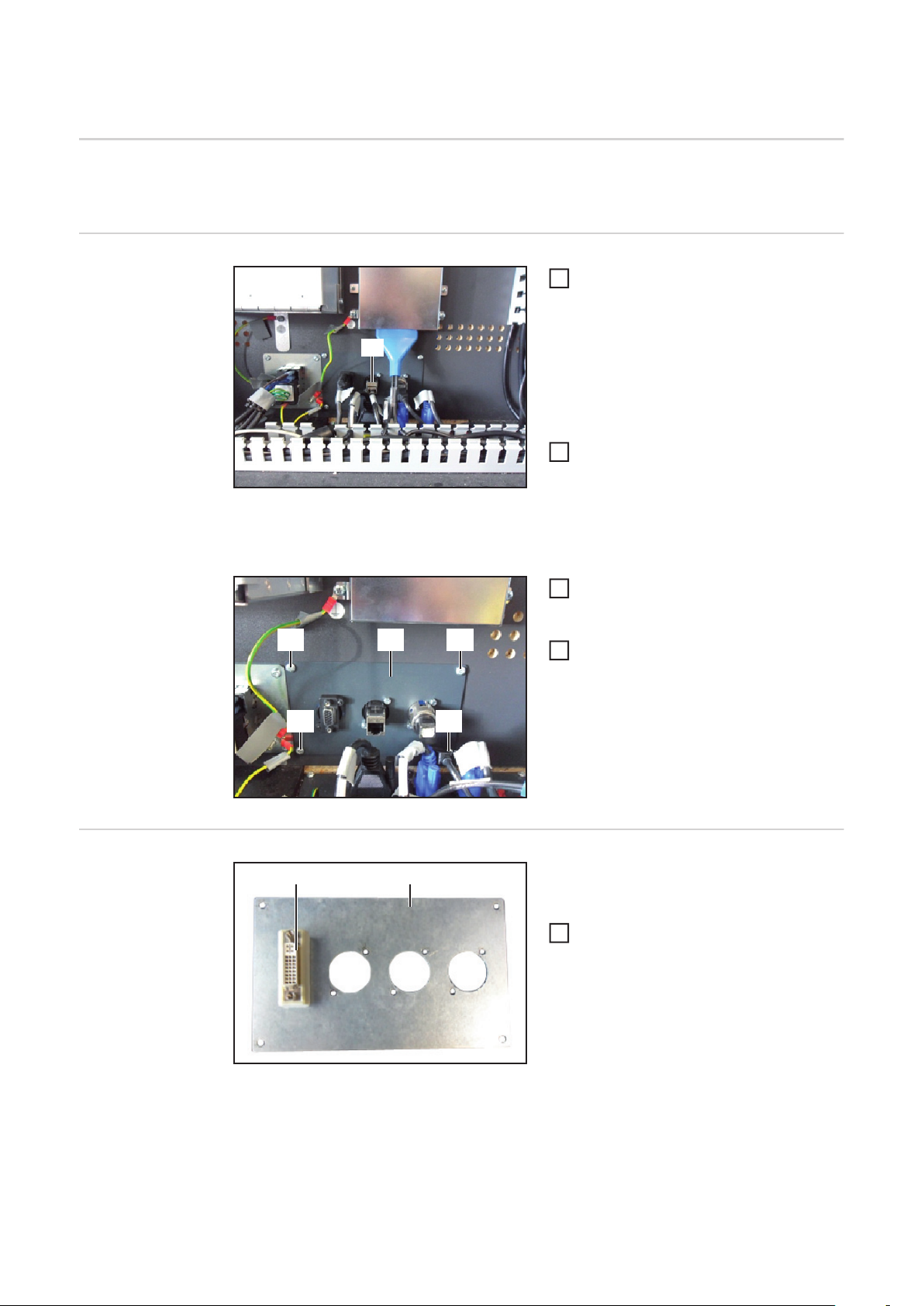
Bestehende Anschlussplatte demontieren
Gehäuse des Virtual Welding-Systems
1
öffnen, so dass freie Sicht auf die Verkabelung und die internen elektronischen Komponenten besteht
(1)
Beim Entfernen des VGA-Kabels darauf
achten, jenes Kabel zu entnehmen, welches zum VGA-Anschluss an der Anschlussplatte führt
Das bestehende VGA-Kabel (1) abste-
1
cken und komplett aus dem Gehäuse
entfernen
Anmerkung: Das bestehende VGA-Kabel wird in einem späteren Arbeitsschritt durch das
mitgelieferte VGA-Kabel ersetzt.
Alle übrigen an der Anschlussplatte (2)
3
angesteckten Leitungen abstecken,
sowohl Gehäuse intern als auch extern
(2)(3) (3)
Alle Schrauben (3) an der An-
4
schlussplatte abschrauben und Anschlussplatte entnehmen
Aktuelle Anschlussplatte bestücken
(3) (3)
(2) (1)
Anschlussplatte: Rückseite
Je nachdem, ob es sich um ein Virtual Welding-Terminal oder ein Virtual Welding-MobileCase handelt:
Die mitgelieferte DVI-Kupplung (2) mit
1
dem zugehörigen SUB-D Abstandshalter an der passenden, ebenfalls mitgelieferte Anschlussplatte (1)
befestigen
6
Page 7
(1)(3)(4)(5) (2)
Anschlussplatte: Vorderseite Anschlussplatte: Rückseite
Mittels Kreuz-Schraubendreher klein und Sechskant-Schlüssel SW 5,5 mm die An-
2
(1) (2) (3) (4) (5)
schlüsse (3), (4) und (5) an der bestehenden Anschlussplatte demontieren
Anmerkung: Im Falle des MobileCase besitzt die Anschlussplatte noch zusätzliche
Anschlüsse, die ebenfalls umzumontieren sind.
Die demontierten Anschlüsse (3), (4) und (5) zusätzlich zur DVI-Kupplung (2) an der
3
mitgelieferten Anschlussplatte (1) montieren
DE
Aktuelle Anschlussplatte einbauen
Aktuelle Anschlussplatte verkabeln
(2) (2)(1)
(1) (2)
Die soeben bestückte Anschlussplatte
1
(1) mittels der ursprünglich verwendeten Schrauben (2) im Gehäuse montieren
(2)(2)
An der Anschlussplatte:
Das mitgelieferte DVI-Kabel (1) an-
1
schließen
Das Adapterkabel VGA/DVI (2) am
2
VGA-Anschluss der Anschlussplatte
anschließen
Die restlichen zuvor abgesteckten Ka-
3
bel anschließen
Gemäß nachfolgend abgebildetem Anschlussplan:
Das DVI-Kabel zur Computerbox verlegen und an dem seitlichen DVI-Port (blau) an-
1
schließen
Das beiliegende VGA-Kabel am Monitor anschließen
2
7
Page 8
Das beiliegende VGA-Kabel zur Computerbox verlegen und an der seitlichen VGA-
3
Buchse der Computerbox anschließen
Nur im Falle eines externen Monitors oder Projektors: Das Adapter-Kabel am optiona-
4
len Verteiler VGA - DVI/VGA (xx,xxxx,xxxx) anschließen. Nähere Informationen dazu
befinden sich in dem Kapitel „Konfigurationen“.
Anschlussplan MobileCase
VGA-Kabel
DVI-Kabel
Adapter-Kabel VGA/DVI
Anschlussplan Terminal
8
Page 9

Helmdisplay anschließen
DE
Helmdisplay anschließen
HINWEIS! Das Helmdisplay (VR-Brille) muss während der Inbetriebnahme des
Virtual-Welding Systemes angeschlossen sein. Wird das Helmdisplay während
des Betriebes angeschlossen, das Virtual Welding-System neu starten. Auf diese
Weise kommt es zu einer Initialisierung des Helmdisplays. Eine Initialisierung des
Helmdisplays kann nur erfolgen, wenn das Helmdisplay in abgeschaltetem Zustand angeschlossen wird.
(2) (1)(3)
Anschlussplatte Terminal Anschlussplatte MobileCase
(3)(2)(1)
Neues Helmdisplay am Virtual Welding-System anschließen
Datenkabel vom Helmdisplay an der Anschlussbuchse Helmdisplay (DVI) (1) anste-
1
cken
Versorgungskabel vom Helmdisplay an der Anschlussbuchse USB (3) anstecken
2
Früheres Helmdisplay am Virtual Welding-System anschließen
Das früher angebotene Helmdisplay funktioniert an der neuen Anschlussplatte nur in Verbindung mit einer speziellen Anschlussbelegung. Detailllierte Informationen dazu befinden
sich in dem Kapitel „Konfigurationen“.
Datenkabel vom Helmdisplay an der Anschlussbuchse Helmdisplay (VGA) (2) anste-
1
cken
Versorgungskabel vom Helmdisplay an der Anschlussbuchse USB (3) anstecken
2
9
Page 10

(4) (5)
Am Controller für das Helmdisplay
Datenkabel (4) für das Helmdisplay an
1
der Anschlussbuchse VGA anstecken
Versorgungskabel (5) für das Helmdis-
2
play an der Anschlussbuchse USB anstecken
(8) (7) (6)
Statusanzeigen am Controller des Helmdisplays
Nr. LED-Farbe Funktion
(6) orange Helmdisplay funktioniert
(6) grün blinkend Helmdisplay befindet sich im Standby
Bedienelemente am Controller des Helmdisplays
Nr. Taste Funktion
(7) Power Das Helmdisplay einschalten
(8) Brightness Durch Drücken der Taste die Helligkeit ändern
10
Page 11
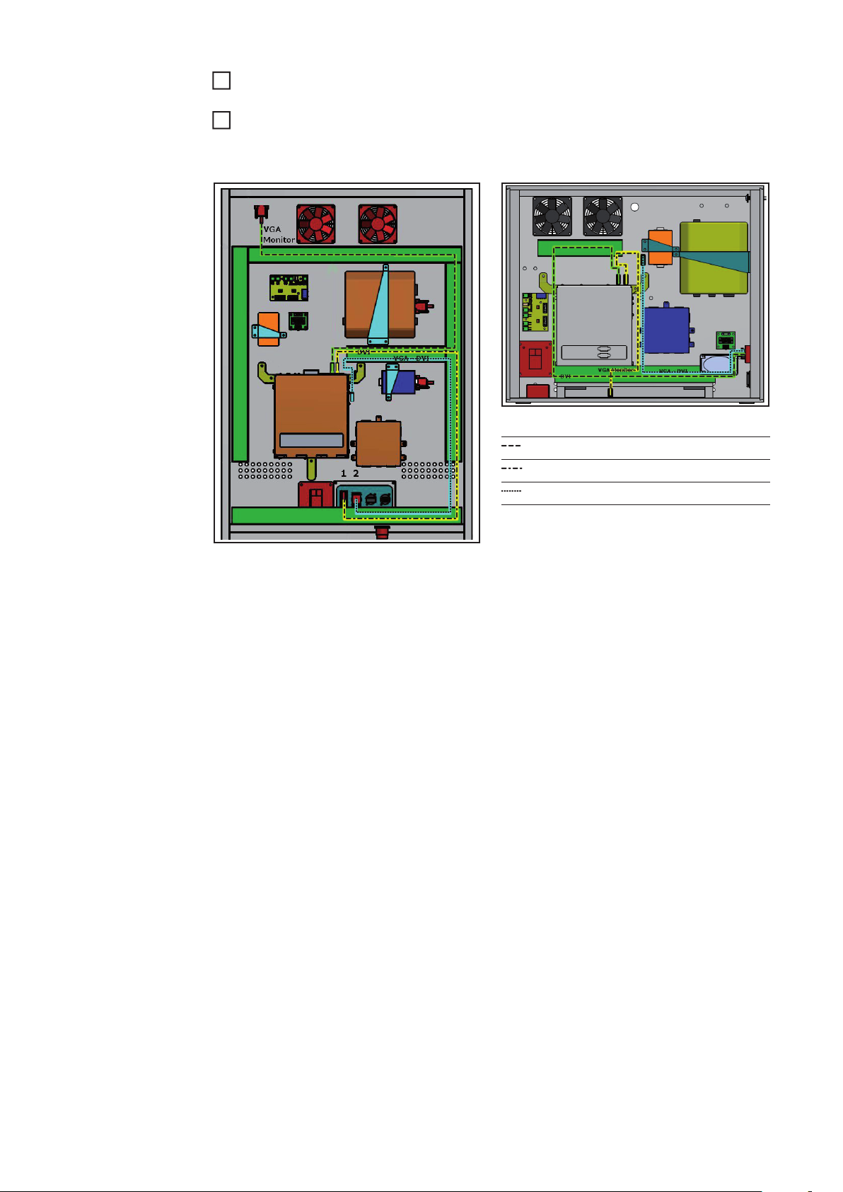
Konfigurationen
Übersicht Je nach Nutzung unterschiedlicher Anzeigemöglichkeiten, kann eine individuelle Verkabe-
lung der Anschlussplatte erforderlich sein. Im Folgenden sind entsprechende Konfigurationsmöglichkeiten angeführt.
- Standardkonfiguration
Das Helmdisplay dient als einzige externe Anzeige
- Externer Monitor oder Projektor
Zusätzlich zum Helmdisplay ist eine weitere externe Anzeige möglich
- Früheres Helmdisplay
An der aktuellen Anschlussplatte wird ein Betrieb des früher angebotenen Helmdisplays unterstützt
Bei allen 3 angeführten Konfigurationen ist sichergestellt, dass die Videokabel in einer
Weise verlegt sind, die ein Umstecken ohne das Öffnen eines Kabelkanales gestattet.
Bei einem Betrieb mit Helmdisplay oder zusätzlichem Monitor benötigt der Hauptbildschirm nach dem Einschalten ein paar Sekunden, bis ein Bild angezeigt wird.
DE
Standardkonfiguration
Externer Monitor
oder Projektor
Für den Betrieb des Virtual Welding-Systems mit dem Helmdisplay, jedoch ohne zusätzliche Anzeigemöglichkeiten, erfolgt die Verkabelung gemäß den zuvor angeführten Anweisungen dieser Einbauanleitung. Zusammenfassend müssen folgende Voraussetzungen
erfüllt sein:
- Das DVI-Kabel ist mit den DVI-Anschlüssen der Anschlussplatte und der Computerbox (Grafikkarte, blaue Buchse) verbunden
- Das VGA-Kabel ist mit den VGA-Anschlüssen des Monitors und der Computerbox
(Grafikkarte) verbunden
- Das Adapterkabel VGA/DVI ist mit dem VGA-Anschluss der Adapterplatte verbunden,
jedoch lediglich an die Computerbox herangeführt und dort nicht angeschlossen
Diese Konfiguration erlaubt zusätzlich zum Helmdisplay eine Anzeige über einen weiteren
Monitor oder Projektor. Gegenüber der Standardkonfiguration sind folgende Änderungen
erforderlich:
Das VGA-Kabel vom Monitor an der Computerbox (Grafikkarte) abstecken
1
An dem nun freien VGA-Anschluss der Computerbox (Grafikkarte) den optionalen
2
Verteiler VGA - DVI/VGA (xx,xxxx,xx) anschließen
Das VGA-Kabel vom Monitor mit dem freien VGA-Anschluss des optionalen Verteilers
3
DVI/VGA verbinden
Das bislang lediglich an die Computerbox herangeführte Adapterkabel VGA/DVI mit
4
dem freien DVI-Anschluss des optionalen Verteilers DVI/VGA verbinden
Früheres Helmdisplay
Anmerkung: Diese Konfiguration nur verwenden, wenn an dem VGA-Anschluss der Anschlussplatte ein Gerät angeschlossen ist, beispielsweise ein Monitor oder Projektor.
Diese Konfiguration erlaubt es, auch das früher angebotene Helmdisplay an der aktuellen
Anschlussplatte zu betreiben. Gegenüber der Standardkonfiguration sind folgende Änderungen erforderlich:
Das DVI-Kabel an der Computerbox (Grafikkarte, blaue Buchse) abstecken, jedoch im
1
Gehäuse belassen
11
Page 12

An dem nun freien DVI-Anschluss der Computerbox (Grafikkarte, blaue Buchse) das
2
bislang lediglich an die Computerbox herangeführte VGA/DVI-Adapterkabel anschließen
12
Page 13

Contents
General ...................................................................................................................................................... 15
Safety.................................................................................................................................................... 15
Components required ........................................................................................................................... 15
Tools required....................................................................................................................................... 15
Replacing the connecting plate.................................................................................................................. 16
General ................................................................................................................................................. 16
Removing the existing connecting plate ............................................................................................... 16
Fitting the new connecting plate ........................................................................................................... 16
Installing the new connecting plate....................................................................................................... 17
Wiring the new connecting plate........................................................................................................... 17
Connecting the helmet display................................................................................................................... 19
Connecting the helmet display.............................................................................................................. 19
Configurations............................................................................................................................................ 21
Overview............................................................................................................................................... 21
Standard configuration.......................................................................................................................... 21
External monitor or projector................................................................................................................. 21
Previous helmet display........................................................................................................................ 21
EN
13
Page 14

14
Page 15

General
Safety
Components required
WARNING! Work that is carried out incorrectly can cause serious injury or dam-
age. All the activities described must only be carried out by Fronius trained service technicians. Do not carry out the activities described until you have
thoroughly read and understood the following documents:
- the operating instructions for the Virtual Welding system, particularly the
safety rules
- the installation instructions for the helmet display
WARNING! An electric shock can be fatal. If the device is plugged into the mains
during installation, there is a high risk of very serious injury and damage. Do not
carry out any work on the device unless
- the mains switch is in the 0 position
- the device is disconnected from the mains
- an easy-to-understand warning sign has been put up to stop anybody inadvertently switching it back on again
- a suitable measuring instrument has been used to ensure that electrically
charged components (e.g. capacitors) have been discharged
The connecting plate conversion kit is required when using the new helmet display on Virtual Welding systems with serial numbers up to and including 2216699.
Depending on whether the Virtual Welding system is a terminal or MobileCase, one of the
two following versions of the conversion kit is required:
- Terminal: StandUp DVI connecting plate
- MobileCase: MobileCase DVI connecting plate
EN
The following components are included in the scope of supply for the connecting plate conversion kit 42,0411,0133:
- 1 x new connecting plate Terminal
- 1 x new connecting plate MobileCase
- 1 x sensor mounting plate
- 2 x 1.8 m VGA cable
- 1 x adapter cable VGA/DVI
- 1 x DVI coupling
- 1 x DVI cable
- 2 x SUB-D spacers
- 1 x DVD
Optional accessories for displaying on another monitor or projector:
- 1 x distributor VGA - DVI/VGA (x,xxxx,xxxx)
Tools required - Large cross-head screwdriver
- Small cross-head screwdriver
- 5.5 mm Allen key
15
Page 16

Replacing the connecting plate
General The following figures illustrate how the conversion is carried out using the Virtual Welding
terminal as an example. The MobileCase is converted in a similar way.
Removing the existing connecting
plate
Open the Virtual Welding system
1
housing so that the cabling and internal
electronic components are clearly visible
(1)
When removing the VGA cable, ensure that
you disconnect the cable leading to the
VGA connection socket on the connecting
plate
Disconnect the existing VGA cable (1)
1
and remove it entirely from the housing
Note: the existing VGA cable is replaced by the supplied VGA cable in a later step.
Disconnect all other leads attached to
3
the connecting plate (2), both inside
and outside the housing
(2)(3) (3)
(3) (3)
Undo all screws (3) on the connecting
4
plate and remove the connecting plate
Fitting the new
connecting plate
16
(2) (1)
Connecting plate: rear view
Depending on whether the system is a
Virtual Welding terminal or a Virtual Welding MobileCase:
Fit the supplied DVI coupling (2) and
1
the corresponding SUB-D spacer to
the appropriate connecting plate (1,
also supplied)
Page 17

(1)(3)(4)(5) (2)
Connecting plate: front view Connecting plate: rear view
Remove the connections (3), (4) and (5) from the existing connecting plate using the
2
(1) (2) (3) (4) (5)
small cross-head screwdriver and the 5.5 mm Allen key
Note: the connecting plate for the MobileCase has other connections that also need
to be refitted.
Fit the removed connections (3), (4) and (5) as well as the DVI coupling (2) to the con-
3
necting plate supplied (1)
EN
Installing the new
connecting plate
Wiring the new
connecting plate
(2) (2)(1)
(1) (2)
Install the newly configured connecting
1
plate (1) in the housing using the original screws (2)
(2)(2)
On the connecting plate:
Connect the supplied DVI cable (1)
1
Connect the VGA/DVI adapter cable
2
(2) to the VGA port of the connecting
plate
Connect all the remaining cables that
3
were disconnected previously
According to the wiring diagram shown below:
Route the DVI cable to the computer box and connect to the DVI port (blue) on the side
1
Connect the enclosed VGA cable to the monitor
2
Route the enclosed VGA cable to the computer box and connect it to the VGA socket
3
on the side of the computer box
17
Page 18

Only in case of an external monitor or projector: Connect the adapter cable to the op-
4
tional distributor VGA - DVI/VGA (xx,xxxx,xxxx). More information can be found in the
chapter „Configurations“.
MobileCase wiring diagram
VGA cable
DVI cable
VGA/DVI adapter cable
Terminal wiring diagram
18
Page 19

Connecting the helmet display
Connecting the
helmet display
NOTE! The helmet display (VR glasses) must be connected when starting up the
Virtual Welding system. If the helmet display is connected during operation, restart the Virtual Welding system in order to initialise the helmet display. An initialisation of the helmet display is only possible if the helmet display is connected in
the switched-off state.
(2) (1)(3)
Terminal connecting plate MobileCase connecting plate
EN
(3)(2)(1)
Connect the new helmet display to the Virtual Welding system
Connect the data cable from the helmet display to the helmet display connection sock-
1
et (DVI) (1)
Connect the supply cable from the helmet display to the USB connection socket (3)
2
Connect the previous helmet display to the Virtual Welding system
At the new connecting plate, the previously offered helmet display only works in conjunction with a special connector assignment. Detailed information is located in the chapter
„Configurations“.
Connect the data cable from the helmet display to the helmet display connection sock-
1
et (VGA) (2)
Connect the supply cable from the helmet display to the USB connection socket (3)
2
(4) (5)
On the helmet display controller
Connect the data cable (4) for the hel-
1
met display to the VGA connection socket
Connect the supply cable (5) for the
2
helmet display to the USB connection
socket
(8) (7) (6)
19
Page 20

Status indicators on the helmet display controller
No. LED colour Function
(6) orange Helmet display working
(6) flashing green Helmet display is in standby
Control elements on the helmet display controller
No. Button Function
(7) Power Switch on the helmet display
(8) Brightness Press the button to change the brightness
20
Page 21

Configurations
Overview Depending on which display options are being used, the connecting plate may have to be
cabled separately. The relevant configuration options are listed below.
- Standard configuration
The helmet display is the only external display
- External monitor or projector
Another external display can be used in addition to the helmet display
- Previous helmet display
Operation of the previous helmet display on the new connecting plate is supported
Care has been taken to ensure that the video cables are routed in the same way in all three
of the above configurations, allowing them to be replugged without having to open up a cable channel.
When operating with the helmet display or an additional monitor, it takes a few seconds
before an image is displayed on the main screen after it has been switched on.
EN
Standard configuration
External monitor
or projector
If the Virtual Welding system is to be operated with the helmet display, but without any additional display options, the cabling is carried out as described earlier in these installation
instructions. In summary, the following requirements must be met:
- The DVI cable is connected to the DVI connection sockets on the connecting plate and
the computer box (graphics card, blue socket)
- The VGA cable is connected to the VGA connection sockets on the monitor and the
computer box (graphics card)
- The VGA/DVI adapter cable is connected to the VGA connection socket on the adapter plate, but is only routed as far as the computer box; it is not connected to it
This configuration allows another monitor or projector to be used for display purposes in
addition to the helmet display. The following changes are required compared with the
standard configuration:
Disconnect the VGA cable from the monitor to the computer box (graphics card)
1
Connect the optional VGA - DVI/VGA distributor (xx,xxxx,xx) to the now free VGA con-
2
nection socket on the computer box (graphics card)
Connect the VGA cable from the monitor to the free VGA connection socket on the
3
optional DVI/VGA distributor
Connect the VGA/DVI adapter cable that has only been routed as far as the computer
4
box up to now to the free DVI connection socket on the optional DVI/VGA distributor
Previous helmet
display
Note: only use this configuration when a device, such as a monitor or projector, is connected to the VGA connection socket on the connecting plate.
This configuration allows also the previous helmet display to be operated on the new connecting plate. The following changes are required compared with the standard configuration:
Disconnect the DVI cable from the computer box (graphics card, blue socket), but
1
leave it in the housing
Connect the VGA/DVI adapter cable that has only been routed as far as the computer
2
box up to now to the free DVI connection socket on the computer box (graphics card,
blue socket)
21
Page 22

22
Page 23

EN
23
Page 24

FRONIUS INTERNATIONAL GMBH
Froniusplatz 1, A-4600 Wels, Austria
Tel: +43 (0)7242 241-0, Fax: +43 (0)7242 241-3940
E-Mail: sales@fronius.com
www.fronius.com
www.fronius.com/addresses
Under http://www.fronius.com/addresses you will find all addresses
of our Sales & service partners and Locations
 Loading...